

Page 1

Operator's Manual
I
ICRnFT. .nN°
LAWN TRACTOR
21.5 HR* 42" Mower
Electric Start
Automatic Transmission
Model No.
917.25574
This product has a low emission engine which operates
differently from previously built engines. Before you start the
engine, read and understand this Operator's Manual.
IMPORTANT:
Read and follow all Safety
Rules and Instructions before
operating this equipment.
Gasoline containing up to 10% ethanol (EIO) is acceptable for use in this machine,
The use of any gasoline exceeding 10% ethanol (El0) wi!l void the product warranty.
Sears Brands Management Corporation, Hoffman Estates, IL 60179 U.S.A,
Visit our Craftsman website:www, sears.comicraftsman *As rated bytheenginemanufacturer
581469827
Page 2
Warranty ................................................ 2
Safety Rules .......................................... 3
Product Specifications ........................... 6
Assem bly/Pre-Operation ....................... 7
Operation ............................................. 10
Maintenance Schedule ........................ 17
Maintenance ........................................ 17
Service and Adjustments ..................... 22
Storage ................................................ 28
Troubleshooting ................................... 29
Craftsman Riding Equipment Warranty
CRAFTSMAN FULL WARRANTY
FOR TWO YEARS from the date of purchase, all non-expendable partsof this riding equipment are
warranted against any defects in material or workmanship. A defective non-expendable part will
receive free in-home repair or replacement if repair is impossible.
FOR FIVE YEARS from the date of purchase, the frame and front axle of this riding equipment are
warranted against anydefects in material orworkmanship.A defective frame or front axle will receive
free in-home repair or replacement if repair is impossible.
FOR 90 DAYS from the date of purchase, the battery (an expendable part) of this riding equipmen'_
is warranted against anydefects in material or workmanship (ourtesting proves that it will not hold a
charge). A defective battery will receive free in-home replacement.
ADDITIONAL LIFETIME LIMITED WARRANTY on CAST IRON FRONT AXLE (if equipped)
FOR AS LONG AS IT IS USED by the original owner after the fifth year from the date of purchase,the
cast ironfront axle (ifequipped) of this riding equipment iswarranted against any defects in material or
workmanship. With proof of purchase, a defective cast front axle will receive free in-home replacement.
WARRANTY SERVICE
For warranty coverage details to obtain free repair or replacement, call 1-800-659-5917 or visitthe
web site: www,craftsman.com
In all cases above, if part repair or replacement is impossible, the riding equipment will be replaced
free of charge with the same or an equivalent model.
All of the above warranty coverage is void if this riding equipment is ever used while providing
commercial services or if rented to another person.
This warranty covers ONLY defects in material and workmanship. Warranty coverage does NOT
include:
• Expendable parts (except battery) that can wear outfrom normal use within the warranty period,
including but not limited to blades, spark plugs, air cleaners, belts, and oil filters.
• Standard maintenance servicing, oil changes, or tune-ups.
• Tire replacement or repair caused by punctures from outside objects, such as nails, thorns,
stumps, or glass.
• Tire or wheel replacement or repair resulting from normal wear, accident, or improper operation or
maintenance.
• Repairs necessary because of operator abuse, including but not limited to damage caused by
towing objects beyond the capability of the riding equipment, impacting objects that bend the
frame, axle assembly or crankshaft, or over-speeding the engine.
• Repairs necessary because of operator negligence, including but not limited to, electrical and
mechanical damage caused by improper storage, failure to use the proper grade and amount
of engine oil, failure to keep the deck clear of flammable debris, orfailure to maintain the dding
equipment according to the instructions contained in the operator's manual.
• Engine (fuel system) cleaning or repairs caused by fuel determined to be contaminated or oxidized
(stale). In general, fuel should be used within 30 days of its purchase date.
• Normal deterioration and wear of the exterior finishes, or product label replacement.
This warranty gives you specific legal rights, and you may also have other rights which vary from
state to state.
Sears Brands Management Corporation, Hoffman Estates, IL 60179
2
Page 3
_DANGER:This cutting machine is capable of amputating hands and feet and
throwing objects. Failure to observe the following safety instructions could result
in serious injury or death.
_WARNING: Inorder to prevent acciden-
tal starting when setting up, transporting,
adjusting or making repairs, always discon-
nect spark plug wire and place wire where
it cannot contact spark plug,
_WARNING: Do not coast down a hill in
neutral, you may lose control of the tractor.
_ILWARNING: Tow only the attachments
that are recommended by and comply with
specifications of the manufacturer of your
tractor. Use common sense when towing,
Operate only at the lowest possible speed
when on a slope, Too heavy of a load, while
on a slope, is dangerous. Tires can lose
traction with the ground and cause you to
lose control of your tractor.
_WARNING: Engine exhaust, some of
its constituents, and certain vehicle compo-
nents contain or emit chemicals known to
the State of California to cause cancer and
birth defects or other reproductive harm.
Ld_IbWARNING:Battery posts, terminals and
related accessories contain lead and lead
compounds, chemicals known tothe State of
California to cause cancer and birth defects
or other reproductive harm. Wash hands
after handling,
L GENERAL OPERATION
• Read, understand, andfoliowallinstruc-
tions on the machine and inthe manual
before starting.
• Do not put hands or feet near rotating
parts or under the machine. Keep clear
of the discharge opening at all times.
• Only allow responsible adults, who are
familiar with the instructions, to operate
the machine,
• Clear the area of objects such as rocks,
toys, wire, etc,, which could bepicked
up and thrown bythe blades.
- Be sure the area is clear of bystanders
before operating. Stop machine ffanyone
enters the area,
• Never carry passengers.
• Do not mow in reverse unless absolutely
necessary. Always lookdown andbehind
before and while backing.
• Never direct discharged materialtoward
anyone. Avoid discharging material
against a wall or obstruction. Material
may ricochet back toward the operator.
Stop the blades when crossing gravel
surfaces.
- Do not operate machine without the en-
tire grass catcher, discharge chute, or
other safety devices in placeand working.
• Slow down before turning,
• Never leave a running machine unat-
tended. Always turn off blades, set
parking brake, stop engine, and remove
keys before dismounting,
• Disengage blades when not mowing,
Shut off engine and wait for all parts to
come toa complete stop before cleaning
the machine, removing the grasscatcher,
or unclogging the discharge chute,
• Operate machine onlyindaylight or good
artificial light,
• Do not operatethe machine while under
the influence of alcohol or drugs.
• Watch for traffic when operating near or
crossing roadways.
• Useextracare whenloading orunloading
the machine into a trailer or truck.
• Always wear eye protection when operat-
ing machine,
• Data indicates that operators, age 60
years and above, are involved in a large
percentage of riding mower-related inju-
ries, These operators should evaluate
their ability to operate the riding mower
safely enough to protect themselves and
others from serious injury.
• Followthe manufacturer's recommenda-
tion for wheel weights or counterweights.
. Keep machine free of grass, leaves or
other debris build-up which cantouch hot
exhaust/engine parts and burn. Do not
allow the mower to plow leaves orother
debris which can cause build-up to oc-
cur.Clean any oil or fuel spillage before
operating or storing the machine. Allow
machine to coo] before storage.
3
Page 4
II. SLOPE OPERATION
Slopes are a major factor related to loss of
control and tip-over accidents, which can
result in severe injury or death. Operation
on all slopes requires extra caution. Ifyou
cannot backup the slope or ifyoufeel uneasy
on it, do not mow it.
- Mow up and down slopes, not across.
• Watch for holes, ruts, bumps, rocks, or
other hidden objects. Uneven terrain
could overturn the machine. Tall grass
can hide obstacles.
• Choose a low ground speed so that you
will not have to stop or shift while on the
slope.
Do not mowon wetgrass. Tires maylose
traction.
Always keep the machine in gear when
going down slopes. Do not shiftto neutral
and coast downhill.
• Avoid starting, stopping, or turning on a
slope. Ifthetires Iosetraction, disengage
the blades and proceed slowly straight
down the slope.
• Keep all movement on the slopes slow
and gradual. Do not make sudden
changes in speed or direction, which
could cause the machine to roll Over.
• Use extra care while operating machine
with grass catchers orother attachments;
they can affect the stability of the ma-
chine. Do no use on steep slopes.
• Do not try to stabilize the machine by
putting your foot onthe ground,
• Do not mow near drop-offs, ditches,
or embankments, The machine could
suddenly roll over if a wheel is over the
edge or if the edge caves in.
!11.CHILDREN
_WARNING: CHILDRENCANBEINJURED
BYTHIS EQUIPMENT.The American Acade-
my of Pediatrics recommends that children
be a minimum of 12 year of age before op-
erating a pedestrian controlled lawn mower
and a minimum of 16 years of age before
operating a riding lawn mower.
Tragic accidents can occur if the operator
is not alert to the presence of children.
Children are often attracted to the machine
and the mowing activity. Never assume
that children will remain where you last
saw them,
• Keep children out of the mowing area
and in the watchful care ofa responsible
adult other than the operator.
• Be alert and turn machine off if a child
enters the area.
• Before and while backing, look behind
and down for small children.
• Nevercarrychildren, evenwiththeblades
shutoff. They mayfall offand beseriously
injured or interfere with safe machine
operation. Children whohave beengiven
ridesin the past may suddenly appear in
the mowing area for another ride and be
runover or backed over by the machine.
• Never allow children to operate the ma-
chine,
• Use extra care when approaching blind
corners, shrubs, trees, or other objects
that may block your view of a child.
IV. TOWING
• Tow only with a machine that has a hitch
designed for towing. Do notattach towed
equipment except at the hitch point.
• Followthe manufacturer's recommenda-
tion for weight timitsfor towed equipment
and towing on slopes.
• Never allow children or others in or on
towed equipment.
• Qnslopes, the weight ofthetowed equip-
ment may cause lossof traction and loss
of control.
• Travel slowly and allow extra distance to
stop.
V. SERVICE
SAFE HANDLING OF GASOLINE
To avoid personal iniury or property dam-
age, use extreme care in handling gasoline.
Gasoline is extremely flammable and the
vapors are explosive.
• Extinguish all cigarettes, cigars, pipes,
and other sources of ignition,
• Use only approved gasoline container,
- Never remove gas cap or add fuel with
the engine running. Allow engine tocool
before refueling.
• Never fuel the machine indoors.
• Neverstorethe machine orfuel container
where there is an open flame, spark, or
pilot light such as on a water heater or
other appliances.
- Never fill containers inside a vehicle or
on a truck ortrailer bed with plastic liner,
Always place containers on the ground
away from your vehicle when filling.
Page 5
. Removegas-poweredequipmentfrom
thetruckortrailerandrefuelitonthe
ground,Ifthisisnotpossible,thenrefuel
suchequipmentwithaportablecontainer,
ratherthanfroma gasolinedispenser
nozzle,
• Keepthenozzleincontactwiththerim
ofthefueltankorcontaineropeningat
alltimesuntilfuelingiscomplete.Donot
useanozzlelock-opendevice.
• fffuelisspilledonclothing,changecloth-
ingimmediately.
• Neveroverfillfueltank.Replacegascap
andtightensecurely,
GENERAL SERVICE
• Never operate machine ina closed area.
• Keep all nuts and boltstightto besurethe
equipment is in safe working condition.
• Never tamper withsafety devices. Check
their proper operation regularly.
• Keep machine free of grass, leaves, or
other debris build-up. Clean oil or fuel
spillage and remove any fuel-soaked de-
bris, Allow machineto cool beforestoring.
• If you strike a foreign object, stop and
inspectthe machine. Repair,if necessary,
before restarting.
• Never make any adjustments or repairs
with the engine running.
• Check grass catcher components andthe
discharge chute frequently and replace
with manufacturer's recommended parts,
when necessary.
• Mowerbtadesaresharp. Wrapthebiade
or wear gloves, and use extra caution
when servicing them,
• Checkbrakeoperationfrequently, Adjust
and service as required,
@@@@
- Maintain or replace safety and instruction
labels, as necessary,
• Be sure the area is clear of bystanders
before operating, Stop machine ifanyone
enters the area.
• Never carry passengers.
• Do not mow in reverse unless absolutely
necessary.Always lookdown andbehind
before and while backing.
• Never carry children, even with the
blades shut off. They may fall off and
be seriously injured or interfere with safe
machine operation. Children who have
been givenrides inthe pastmaysuddenly
appear in the mowing area for another
ride and be run over or backed over by
the machine.
• Keep children out of the mowing area
and in the watchful care ofa responsible
adult other than the operator.
• Be alert and turn machine off if a child
enters the area,
• Before and while backing, look behind
and down for small children.
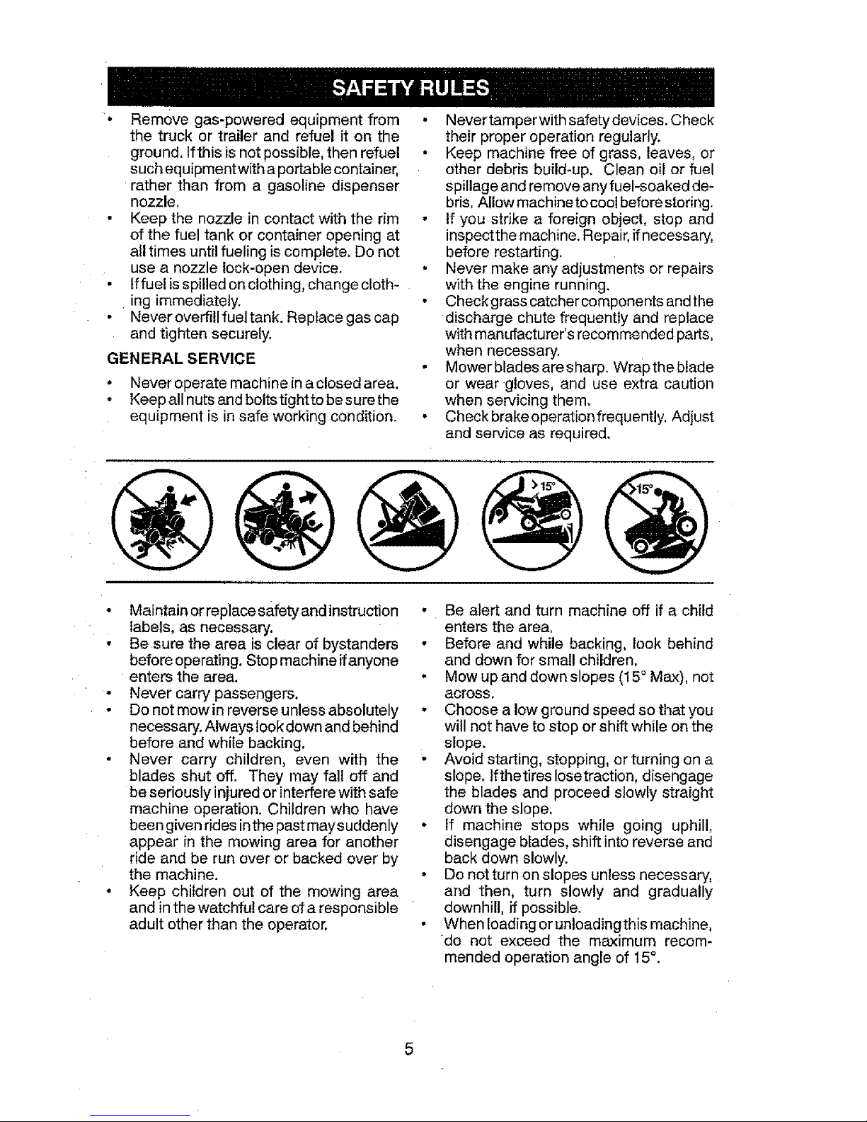
. Mow up and down slopes (15° Max), not
across.
• Choose a low ground speed so that you
will not have to stop or shift while on the
slope.
• Avoid starting, stopping, or turning ona
slope, lfthetires Iosetraction, disengage
the blades and proceed slowly straight
down the s]ope.
• If machine stops while going uphill,
disengage blades, shift intoreverse and
back down slowly.
• Do not turn on slopes unless necessary,
and then, turn slowly and gradually
downhill, if possible.
• Whenloadingorunloadingthismachine,
do not exceed the maximum recom-
mended operation angle of 15°.
5
Page 6

PRODUCT SPECIFICATIONS
Gasoline Capacity 3,0 Gallons/l 1,35 L
and type: Regular Unleaded
Oil Type: SAE 30 (above 32_F/0°C
(API: SG-SL) SAtE 5W30 (below 32°F/0°C
Oil Capacity: W/Filter: 64 Oz./1.96 L
W/out Filter,' 52 Oz./1,5 L
Spark Plug: Champion QC12YC
(Gap: .040"/1.02 mm)
Charging 3 Amps Battery
System: 5 Amps Headlights
Battery: Amp/Hr: 28
Min, CCA: 230
Case size: U1R
Blade Bolt Torque: 45-55 Ft. Lbs,/62-75 Nm
CONGRATULATIONS onyour purchase of
a new tractor, tt has been designed, engi-
neeredand manufactured togiveyouthe best
possible dependability and performance.
Shouldyou experience any problemyoucan-
not easily remedy, please contact a Sears or
otherqualifiedservicecenter. We havecom-
petent, well-trained representatives andthe
proper tools to service orrepair this tractor.
Please read and retain this manual. The
instructions wilj enable you to assembJe
and maintain your tractor properly. Always
observe the "SAFETY RULES".
CUSTOMER RESPONSIBILITIES
• Read and observe the safety rules,
• Follow a regular schedule in maintaining,
caring for and using your tractor.
• Follow instructionsunder "Maintenance"
and "Storage" sections of this manual,
• Wear proper Personal Protective Equip-
ment (PPE) while operating this machine,
including (at a minimum) sturdy footwear,
eyeprotection, andhearing protection, Do
notmowinshortsand!oropentoedfootwear.
• Always letsomeone knowyou are outside
mowing.
_WAR NING: This tractor isequipped with
an internal combustion engine and should
not be used on or near any unimproved
forest-covered, brush-covered or grass-
covered land unless the engine's exhaust
system is equipped with a spark arrester
meeting applicable local or state laws (if
any), If a spark arrester is used, it should
be maintained ineffective working order by
the operator.
Inthe state ofCaliforniathe above isrequired
by law (Section 4442 ofthe California Public
Resources Code). Other states may have
similar laws. Federal laws apply on federal
lands. A spark arrester for the muffler is
availablethrough your nearest Searsservice
center (See REPAIR PARTS manual).
Page 7
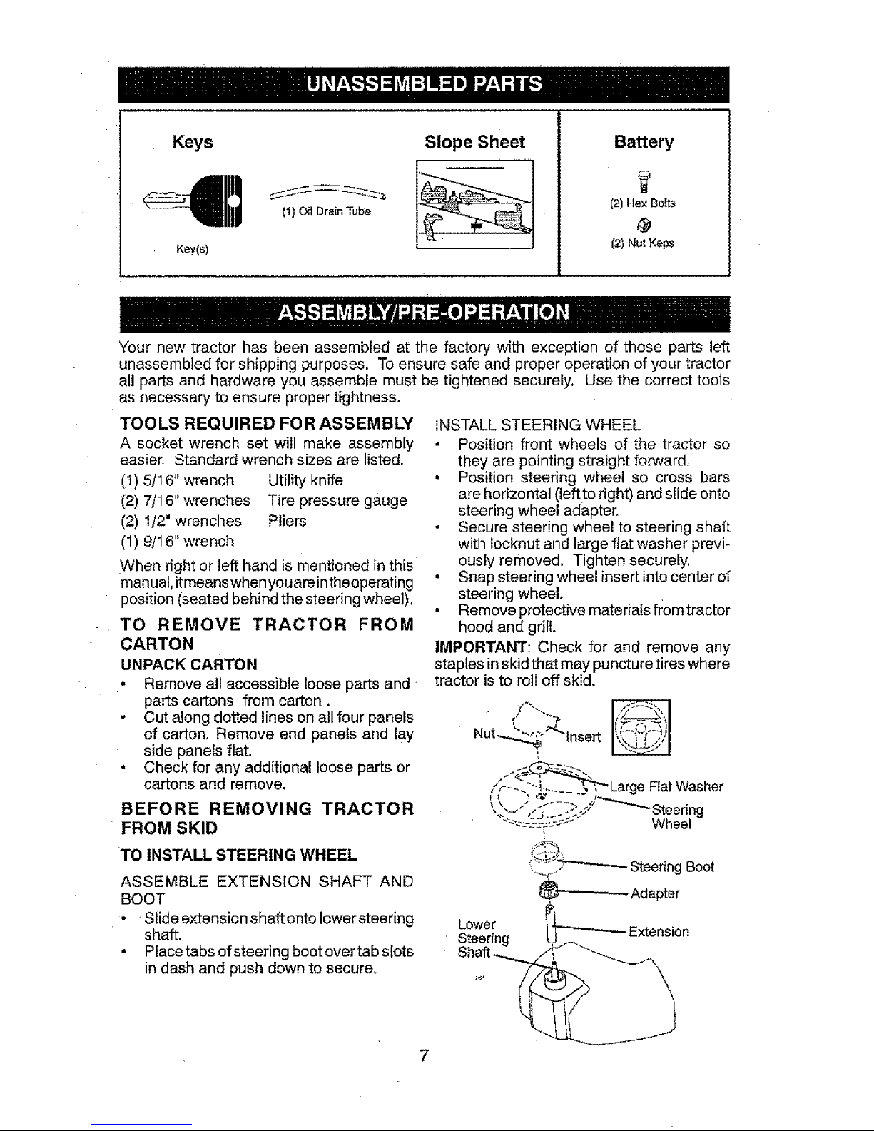
Keys
Key(s)
(t) Oil Drain Tube
Slope Sheet Battery
(2) Hex Bolts
(2) Nut Keps
Your new tractor has been assembled at the factory with exception of those parts left
unassembled for shipping purposes. To ensure safe and proper operation of your tractor
all parts and hardware you assemble must be tightened securely. Use the correct tools
as necessary to ensure proper tightness,
TOOLS REQUIRED FOR ASSEMBLY
A socket wrench set will make assembly
easier. Standard wrench sizes are listed.
(I) 5/16" wrench Utility knife
(2) 7/16" wrenches Tire pressure gauge
(2) 1/2" wrenches Pliers
(1) 9/16" wrench
When right or left hand is mentioned in this
manual,itmeanswhen youareintheoperating
position (seated behind the steering wheel),
TO REMOVE TRACTOR FROM
CARTON
UNPACK CARTON
. Remove all accessible loose parts and
parts cartons from carton.
- Cut along dotted lines on all four panels
of carton. Remove end panels and lay
side panels flat.
. Check for any additional loose parts or
cartons and remove.
BEFORE REMOVING TRACTOR
FROM SKID
TO INSTALL STEERING WHEEL
ASSEMBLE EXTENSION SHAFT AND
BOOT
• ' Slide extension shaft onto lower steering
shaft.
• Placetabs ofsteering bootovertabs[ots
in dash and push down to secure.
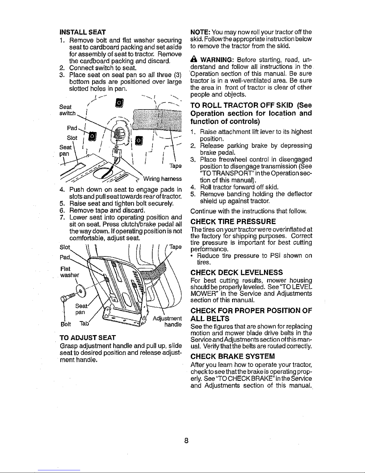
INSTALL STEERING WHEEL
Position front wheels of the tractor so
they are pointing straight forward,
• Position steering wheel so cross bars
arehorizontal (leftto right) and slide onto
steering wheel adapter.
• Secure steering wheel to steering shaft
with locknut and large flat washer previ-
ously removed. Tighten securely,
• Snap steering wheel insert into center of
steering wheel.
• Remove protective materials fromtractor
hood and griE
IMPORTANT: Check for and remove any
staples in skid that may puncture tires where
tractor is to roll off skid.
Nut_ "_"-insert
('F--._-_,_.__ _ Large FiatWasher
_--'-'_ Adapter
L_eweirg _'------ Extension
Page 8
INSTALL SEAT
1. Remove bolt and flat washer securing
seat to cardboard packing and set aside
for assembly ofseat to tractor. Remove
the cardboard packingand discard.
2. Connect switch to seat.
3. Place seat on seat pan so all three (3)
bottom pads are positioned over large
slotted holes in pan.
Seat / _-' _' _'"
switch /
Pad.
Slot
J
I /
I
Tape
Wiring harness
4. Push down on seat to engage pads in
slotsand pullseat towards rearoftractor.
5. Raise seat and tighten bolt securely.
6. Remove tape and discard.
7. Lower seat into operating position and
sit on seat, Press clutch/brake pedal atl
the way down. Ifoperating positionisnot
comfortable, adjust seat,
R_
washer
\
Adjustment
Bolt handle
TO ADJUST SEAT
Grasp adjustment handle and pullup, slide
seat to desired positionand release adjust-
ment handle.
NOTE: You may now rollyour tractor offthe
skid. Followthe appropriate instructionbelow
to remove the tractor from the skid.
WARNING: Before starting, read, un-
derstand and follow all instructions in the
"Operation section of this manual. Be sure
tractor is in a well-ventilated area. Be sure
the area in front of tractor is clear of other
people and objects,
TO ROLL TRACTOR OFF SKID (See
Operation section for location and
function of controls)
1. Raise attachment lift lever to its highest
position.
2. Release parking brake by depressing
brake pedal.
3. Place freewheel control in disengaged
position to disengage transmission (See
"TO TRANSPORT" inthe Operation sec-
tion of this manual).
4. Roll tractor forward off skid.
5. Remove banding holding the deflector
shield upagainst tractor.
Continue with the instructions that follow.
CHECK TIRE PRESSURE
The tires on your tractor were overinfiated at
the factory for shipping purposes. Correct
tire pressure is important for best cutting
performance.
• Reduce tire pressure to PSt shown on
tires.
CHECK DECK LEVELNESS
For best cutting results, mower housing
should be properlyleveled. See"TO LEVEL
MOWER in the Service and Adjustments
section of this manual.
CHECK FOR PROPER POSITION OF
ALL BELTS
See the figures that are shown for replacing
motion and mower blade drive belts in the
ServiceandAdjustments section ofthisman-
ual. Verifythatthe belts are routed correctly.
CHECK BRAKE SYSTEM
After you learn how to operate your tractor,
checkto see that the brake isoperating prop-
erly. See"TO CHECK BRAKE" intheService
and Adjustments section of this manual.
8
Page 9

,/'CHECKLIST
Before you operate your new tractor, we
wish to assure that you receive the best
performance and satisfaction from this
Qualib] Product.
Please review the following checklist:
`/All assembly instructions have been com-
pleted.
`/No remaining loose parts in carton.
,/Battery is properly prepared and
charged.
,/Seatis adjusted comfortablyandtightened
securely.
J All tires are properly inflated. (For ship-
ping purposes, the tires were overinflated
at the factory).
`/Be sure mower deck is properly leveled
side-to-side!front-to-rear for best cutting
results. (Tires must be properly inflated
for leveling).
J Check mower and drive belts, Be sure
they are routed properly around pulleys
and inside all belt keepers.
`/Check wiring. See that all connections
are still secure and wires are properly
clamped.
`/Before driving tractor, be sure freewheel
control is in "transmission engaged"
position (see "TO TRANSPORT" in the
Operation section of this manual).
While learninghowto useyourtractor, payex-
traattention tothe following important items:
`/Engine oil is at proper level.
,/Fuel tank isfilled with fresh, clean, regular
unleaded gasoline.
,/Become familiar with all controls, their lo-
cation and function. Operatethem before
you start the engine.
,/Be sure brake system is in safe operating
condition.
v" Be sure Operator Presence System and
Reverse Operation System (ROS) are
working properly (Seethe Operation and
Maintenance sections inthis manual).
v"Itisimportantto purgethetransmissionbefore
operatingyour tractorfor the first time. Fol-
low properstartingandtransmission purging
instructions(See"TOSTART ENGINE"and
"PURGETRANSMISSION" intheOperation
section ofthis manual).
Page 10
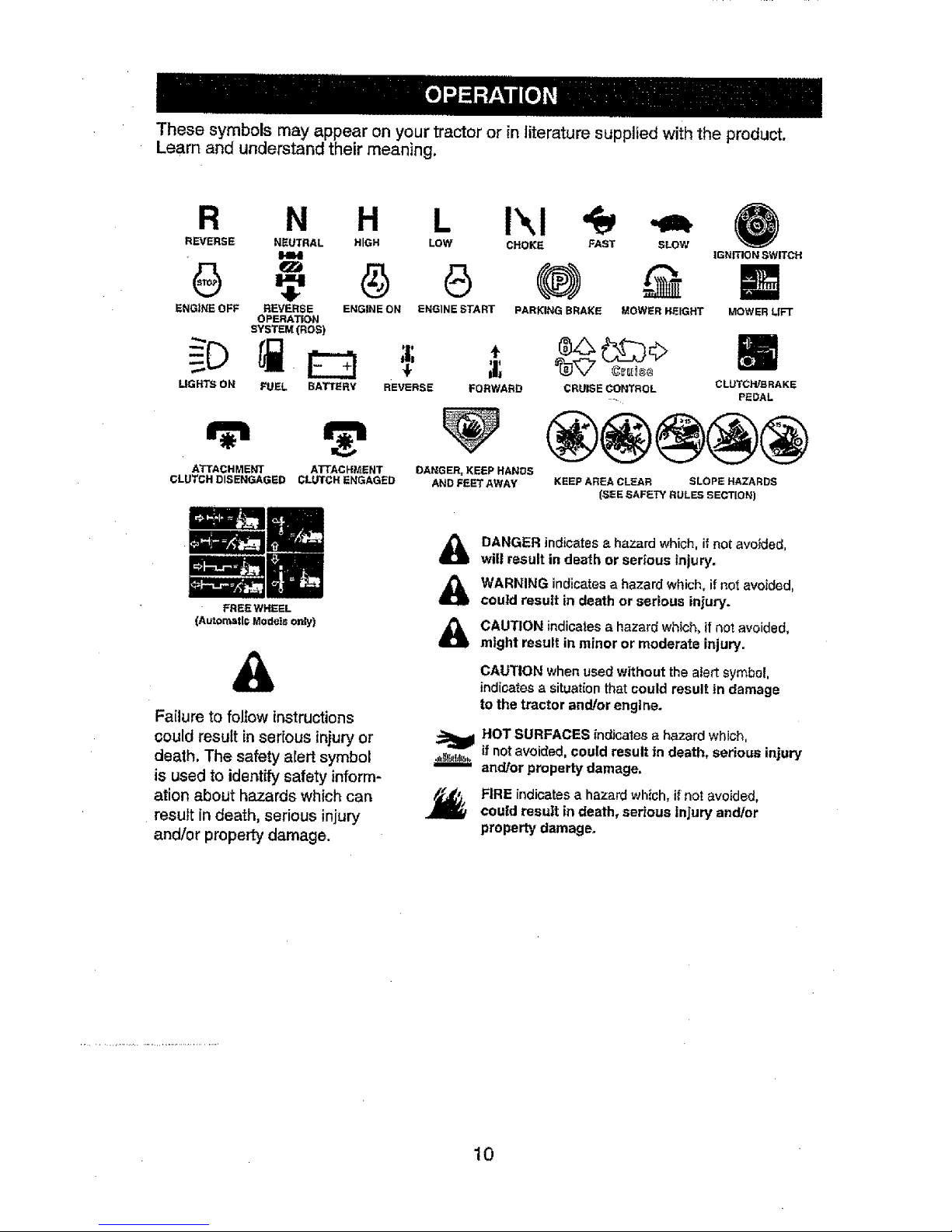
ThesesymbolsmayappearonyourtractororinJiteraturesuppliedwiththeproduct.
Learn and understand their meaning,
R N H L
REVERSE NEUTRAL HIGH LOW
ENGINE OFF REVERSE ENGINE ON ENGINE START
OPERA'_ON
SYSTEM(ROe)
÷
UGHTS ON FUEL BATTERY REVERSE FORWARD
ATTACHMENT A'rrACHMENT
CLUTCH DISENGAGED CLUTCH ENGAGED
FREE WHEEL
(Automatic Models only)
Failure to follow instructions
could result in serious injury or
death. The safety alert symbol
is used to identify safety inform-
ation about hazards which can
result in death, serious injury
and/or property damage.
DANGER_ KEEP HANDS
AND FEET AWAY
!\!
CHOKE FAST SLOW
PARKING BRAKE MOWER HEIGHT
IGNmON SWITCH
MOWER LIFT
CRUISE CONTROL CLUTCWBRAKE
.... PEDAL
KEEP AREA CLEAR SLOPE HAZARDS
(SEE SAFETY RULES SECTION)
DANGER indicates a hazard which, if not avoided,
wilt result in death or serious injury.
WARNING indicates a hazard which, if not avoided.
could result in death or serious injury.
CAUTION indicates a hazard which, if not avoided,
might result in minor or moderate injury.
CAUTION when used without the ater[ symbol,
indicates a situation that could result in damage
to the tractor and/or engine.
HOT SURFACES indicales a hazard which,
,,,_it_!,_..if not avoided, could result in death, serious injury
and/or property damage.
FIRE indicates a hazard which, if not avoided,
could result in death, serious injury and/or
property damage.
10
Page 11
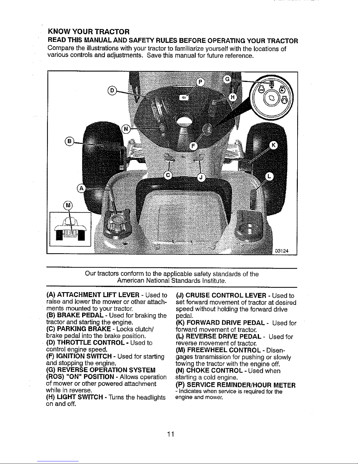
KNOW YOUR TRACTOR
READ THIS MANUAL AND SAFETY RULES BEFORE OPERATING YOUR TRACTOR
Compare the illustrations with your tractorto familiarize yourself with the locationsof
various controls and adjustments. Save this manual for future reference.
Our tractors conform to the applicable safety standards of the
American National Standards institute,
(A) ATTACHMENT LIFT LEVER - Used to
raise and lower the mower or other attach-
ments mounted to your tractor,
(B) BRAKE PEDAL - Used for braking the
tractor and starting the engine.
(C) PARKING BRAKE - Locks clutch!
brake pedal into the brake position.
(D) THROTTLE CONTROL - Used to
control engine speed.
(F) IGNITION SWITCH - Used for starting
and stopping the engine.
(G) REVERSE OPERATION SYSTEM
(ROS) "ON" POSITION - Allows operation
of mower or other powered attachment
while in reverse.
(H) LIGHT SWITCH - Turns the headlights
on and off.
(J) CRUISE CONTROL LEVER - Used to
set forward movement of tractor at desired
speed without holding the forward drive
pedal.
(K) FORWARD DRIVE PEDAL- Used for
forward movement of tractor.
(L) REVERSE DRIVE PEDAL- Used for
reverse movement of tractor.
(M) FREEWHEEL CONTROL - Disen-
gages transmission for pushing or slowly
towing the tractor with the engine off,
(N) CHOKE CONTROL - Used when
starting a cold engine.
(P) SERVICE REMINDER!HOUR METER
- Indicates when service isrequired for the
engine and mower.
11
Page 12

The operation of any tractor can result in foreign objects thrown int4
the eyes, which can result in severe eye damage, Always wear safety1
glasses or eye shields while operating your tractor or performing anyl
adjustments or repairs. We recommend standard safety glasses ora I
wide vision safety mask worn over spectacles. !
HOW TO USE YOUR TRACTOR
TO SET PARKING BRAKE
Your tractor is equipped with an operator
presence sensing switch. When engine is
running, anyattempt bythe operatorto leave
the seatwithout firstsetting the parking brake
will shut off the engine.
t. Depress brake pedal (B)allthe way down
and hold.
2, Pull parking brake lever (C) upand hold,
release pressurefrom brake pedal (B),
then release parking brake lever, Pedal
should remain in brake position. Make
sure parking brake will hold tractor se-
cure.
STOPPING
MOWER BLADES -
• Tostop mower blades, move attachment
clutch controlto disengaged position (f_t).
NOTE: Failureto movethrottle controlto slow
positionand allowing engine to idlebefore
stopping may cause engine to "backfire".
• "SJrnignition key (F) to "STOP" position
and removekey.Always removekeywhen
leavingtractortopreventunauthorized use.
• Never use choke to stop engine.
IMPORTANT: Leaving the ignition switch in
anyposition otherthan "STOP"will causethe
battery to discharge and go dead.
NOTE: Undercertainconditions whentractor
isstanding idle with the engine running, hot
engine exhaust gases may cause "brown-
ing" of grass. To eliminate this possibility,
always stop engine when stopping tractor
on grass areas.
CAUTION: Always stop tractor com-
pletely, as described above, before leaving
the operator's position,
TO USE THROTrLE CONTROL (D)
Always operate engine at full speed (fast).
° Operating engine at less than full speed
(fast) reduces engine's operating effi-
ciency.
• Full speed (fast) offers the best mower
performance.
(1_1) Attachment (1_) Attachment
Clutch Control Clutch Control
"Engaged .... Disengaged"
GROUND DRIVE -
° Tostopground drive, depress brakepedal
all the way down.
IMPORTANI_ Forward and reverse drive
pedals return to neutral position when not
depressed,
ENGINE -
• Move throttle control (D)to slow position.
12
TO USE CHOKE CONTROL (N)
Use chokecontrolwhenever you are start-
ing a cold engine. Do not use to start a
warm engine.
• Toengage choke control, pull knob out,
Slowly push knob in to disengage.
TO MOVE FORWARD AND BACKWARD
The direction and speed of movement
iscontrolledby the forward and reverse
drive pedals,
1. Start tractorand release parking brake,
2. Slowly depressforward (K)orreverse(L)
drive pedal to begin movement, Ground
speed increases the further down the
pedal isdepressed.
Page 13

TO USE CRUISE CONTROL
The cruise control feature can be used for
forward travel only.
SYSTEM CHARACTERISTICS
The cruise control should only be used
while mowing or transporting on relatively
smooth, straight surfaces. Other conditions
such astrimming atslow speeds may cause
the cruise control to disengage. Donot use
the cruise control on slopes, rough terrian
or while trimmimg or turning,
• With forward drive pedal (K) depressed to
desired speed, pullcruise control lever (J)
up and hold while lifting your foot off the
pedal, then release the lever.
Todisengagethe cruise control, depress the
brake pedal or tap on forward drive pedal.
TO ADJUST MOWER CUTTING HEIGHT
The position of the attachment lift lever (A)
determines the cutting height.
• Put attachment lift lever in desired cut-
ting height slot.
The cutting height range is approximately
1" to 4". The heights are measured from
the ground to the blade tip with the engine
not running. These heights are approximate
and may vary depending upon soil condi-
tions, height of grass and types of grass
being mowed,
• The average lawn should be cut to ap-
proximately 2-1/2" during the cool sea-
son and to over 3" during hot months.
For healthier and better looking lawns,
mow often and after moderate growth.
• For best cutting performance, grass over
6" in height should be mowed twice. Make
the first cut relatively high; the second to
desired height.
TO ADJUST GAUGE WHEELS
Gauge wheels are properly adjusted when
they are slightly off the ground when mower
is at the desired cutting height in operating
position. Gauge wheels then keep the deck
in proper position to help prevent scalping
in most terrain conditions.
NOTE: Adjust gauge wheels with tractor on
aflat level surface,
1. Adjust mower to desired cutting height
(See "TO ADJUST MOWER CUTTING
HEIGHT" in this section of manual),
2. With mower in desired height of cut posi-
tion, gauge wheels should beassembled
so they areslightly offthe ground. Install
gauge wheel in appropriate hole. Tighten
securely.
3, Repeat for all, installinggauge wheel
in same adjustment hole.
TO OPERATE MOWER
Your tractor is equipped with an operator
presence sensing switch. Any attempt
by the operator to leave the seat with the
engine running and the attachment clutch
engaged will shut off the engine. You must
remain fully and centrally positioned in the
seat to prevent the engine from hesitating or
cutting off when operating your equipment
on rough, rolling terrain or hills.
1. Select desired height ofcut with attach-
ment lift lever.
2. Start mower blades by engaging attach-
ment clutch control.
TO STOP MOWER BLADES
Disengage attachment clutch control.
_JLCAUTION: Do not operate the mower
without either the entire grass catcher, on
mowers soequipped, orthe deflector shield
(S) inplace.
13
Page 14

REVERSE OPERATION SYSTEM (ROS)
Your tractor is equipped with a Reverse
Operation System (ROS). Any attempt by
the operatortotravel inthereversedirection
withthe attachmentclutchengaged wiI]shut
off the engine unless ignitionkey is placed
in the ROS "ON" position.
,_iLWARNING: Backing up with the at-
tachment clutchengaged while mowing is
stronglydiscouraged.TurningtheROS"ON",
to allow reverse operation with the attach-
ment clutch engaged, shouldonlybe done
whenthe operator decides it is necessary to
repositionthe machine withthe attachment
engaged. Do not mow in reverse unless
absolutely necessary.
USING THE REVERSE OPERATION
SYSTEM -
Only use if you are certain no children or
other bystanders will enter the mowing area.
1. Depress brake pedal all the way down.
2. With engine running, turn ignition key
counterclockwise to ROS "ON" position,
3. Look down and behind before and while
backing,
4. Slowly depress reverse drive pedal to
start movement.
5. When useofthe ROSisnolonger needed.
turn the ignition key clockwise to engine
"ON" position.
RQS"ON"Position Engine"ON"Position
(NormalOperating)
TO OPERATE ON HILLS
_I_WARNING: Do not drive up or down
hills withslopes greaterthan 15_and donot
drive across any slope. Use the slope guide
provided at the back of this manual.
• Choose the slowest speed before start-
ing up or down hills,
• Avoidstoppingorchangingspeedon hills.
• if stopping is absolutely necessary, push
brake pedal quickly to brake position and
engage parking brake.
o To restart movement, slowly release park-
ing brake and brake pedal
• Slowly depress appropriate drive pedal to
slowest setting.
o Make all turns slowly.
TO TRANSPORT
When pushing or towing your tractor, be
sure to disengage transmission by placing
freewheel control in freewheeling position.
Freewheel control is located at the rear
drawbar of tractor,
1. Raise attachment lift lever to its highest
position.
2. Pullfreewheel control out and intothe slot
andreleaseso itis heldinthe disengaged
position,
• Do not push or tow tractor at more than
two (2) MPH,
• Tore-engage transmission, reverse above
procedure.
Transmission Engaged
Transmission Disengaged
NOTE: To protect hoodfrom damage when
transporting your tractor onatruck or atrailer,
besure hood isclosed and secured to tractor,
Use an appropriate means of tying hood to
tractor (rope, cord, etc.).
TOWING CARTS AND OTHER ATTACH-
MENTS
Tow only the attachments that are recom-
mended by and comply with specifications
of the manufacturer of your tractor. Use
common sense when towing. Too heavy of
aload, while on a slope, is dangerous. Tires
can lose traction with the ground and cause
you to Josecontrol of your tractor,
SERVICE REMINDER/HOUR METER
Service reminder shows the total number of
hoursthe engine has run and indicateswhen
the engine or mower needs servicing, After
every 50 hours of operation the oil can icon
will stayonfor 2hours or until amanual reset
occurs. To reset the display manually turn
the ignition switch to the on position, then
the off position five times (1 second on, 1
second off), To service engine and mower,
seethe Maintenance section of this manual.
Note: Service reminder runs when the
ignition key is in any position but "STOP",
For accurate reading, be sure key remains
in the "STOP" position when engine is not
running.
14
Page 15

BEFORE STARTING THE ENGINE
CHECK ENGINE OIL LEVEL
Theengine inyour tractor has beenshipped,
from the factory, already filled with summer
weight oil.
1. Check engine oil with tractor on level
ground.
2. Remove oil fill cap/dipstick and wipe
clean, reinsert the dipstick andscrew cap
tight, wait for afew seconds, remove and
read oil level. If necessary, add oil until
"FULL' mark on dipstick is reached. Do
not overfill.
• For cold weather operation you should
change oil for easier starting (Seethe oil
viscosity chart in the Maintenance section
of this manual),
• Tochangeengine oU,seethe Maintenance
section inthis manual.
ADD GASOLINE
•Fili fuel tank to bottom of filler neck. Do
not overfill. Use fresh, clean, regular
unleaded gasoline with a minimum of
87 octane. (Use of leaded gasoline will
increase carbon and lead oxide deposits
and reduce valve life). Do not mix oilwith
gasoline. Purchase fuel in quantities that
can be used within 30 days to assure fuel
freshness.
ACAUTION: Wipe offany spilled oil or fuel,
Do not store, spill or use gasoline near an
open flame.
IMPORTANT: When operating in tempera-
tures below 32°F(0°C), use fresh, clean
winter grade gasoline to help insure good
cold weather starting,
CAUTION: Alcohol blended fuels (called
gasohol or using ethanol or methanol) can
attract moisture which leads to separation
andformation ofacids during storage. Acidic
gascan damage thefuei systemofan engine
while in storage. Toavoid engine problems,
the fuel system should be emptied before
storage of 30 days or longer. Drainthe gas
tank, start the engine and let it run until the
fuel lines and carburetor are empty, Use
fresh fuel next season. SeeStorage Instruc-
tions for additional information. Never use
engine or carburetor cleaner products inthe
fuel tank or permanent damage may occur.
TO START ENGINE
When starting the engine for thefirst time or
if the engine has run out of fuel, it will take
extra cranking time to move fuel from the
tank to the engine.
1. Be sure freewheel control is inthe trans-
mission engaged position.
2. Siton seat in operating position, depress
3. Move attachment clutch to disengaged
position.
4. Move throttle control to fast position
5. Pull choke control out for a cold engine
start attempt. For a warm engine start
attempt the choke control may not be
needed.
NOTE: Before starting, read the warm and
cold starting procedures below.
6. Insert key into ignition and turn key
clockwise to start position and release
keyas soon as engine starts. Do not run
starter continuously for more than fifteen
seconds per minute. If the engine does
not start after several attempts, push
choke control in, wait afew minutes and
try again. If engine still does not start,
pull the choke control out and retry.
WARM WEATHER STARTING
(50°F (10°C) and above)
7. When engine starts, slowly push choke
control in until the engine begins to run
smoothly. If the engine starts to run
roughly, pullthe choke controi outslightly
for a few seconds and then continue to
push the control in slowly.
• The attachments and ground drive
can now be used. If the engine does
not accept the load, restart the engine
and allow itto warm up for one minute
using the choke as described above.
COLD WEATHER STARTING
(50°F (10°C) and below)
7, When engine starts, slowly push choke
control in until the engine begins to run
smoothly. Continue to push the choke
control in small steps allowing the engine
to accept small changes in speed and
load, until the choke control is fully in.
If the engine starts to run roughly, pull
the choke control out slightly for a few
seconds and then continue to push the
control in slowly, This may require an
engine warm-up period from several
seconds to several minutes, depending
on the temperature.
AUTOMATIC TRANSMISSION WARM UP
Before driving the unit in cold weather, the
transmission should be warmed up as fol-
lows:
1. Be sure the tractor is on level ground.
2, Release the parking brake and let the
brake slowly return tooperating position.
3. Allow one minute for transmission to
warm up. This can be done during the
engine warm up period.
brake pedal and set parking brake.
15
Page 16

• The attachments can be used during
the engine warm-up period after the
transmission has been warmed up
and may require the choke control be
pulled out slightly.
NOTE: tfata high altitude (above 3000 feet)
or in cold temperatures (below 32°F (O°C))
the carburetor fuel mixture may need to be
adjusted for best engine performance (see
"TOADJUST CARBURETOR" in the Service
and Adjustments section of this manual).
PURGE TRANSMISSION
_CAUTION: Never engage or disengage
freewheel lever while the engine is running.
Toensure properoperation and performance,
itis recommended that the transmission be
purged before operating tractor for the first
time.This procedure will remove anytrapped
air inside the transmission which may have
developed during shipping of your tractor.
IMPORTANT: Should your transmission
require removal for service orreplacement,
itshould be purged after reinstallation before
operating the tractor.
1. Place tractor safely on a level surface -
that is clear of objects and open - with
engine off and parking brake set,
2. Disengage transmission by placing
freewheel control in disengaged position
(See "TO TRANSPORT" in this section
of manual).
3. Sitting in the tractor seat, start engine.
After the engine isrunning, move throttle
control to stow position. Disengage park-
ing brake.
_!4]kCAUTION: At any time, during step 4,
there may be movement ofthe drive wheels.
4. Depressforward drive pedal tofull forward
position and holdforfive (5)seconds and
release pedal. Depress reverse drive
pedal to full reverse position and hold
for five (5) seconds and release pedal.
Repeat this procedure three (3) times,
5. Shutoff engine and set parking brake.
6. Engage transmission by placing free-
wheel control in engaged position (See
"TO TRANSPORT" in this section of
manual).
7. Sitting in the tractor seat, start engine.
After the engine is running, movethrottle
control to half (1/2) speed. Disengage
parking brake,
8. Drive tractor forward for approximately
five feet then backwards for five feet.
Repeatthis driving procedurethreetimes.
'four transmission is now purged and now
ready for normal operation.
16
MOWING TIPS
• Tire chains cannot be used when the
mower housing is attached to tractor.
• Mower should be properly leveled for
best mowing performance. See "TO
LEVEL MOWER HOUSING" in the
Service and Adjustments section of this
manual,
• The left hand side of mower should be
used for trimming,
• Drive sothat clippings are discharged
onto the area that has already been
cut. Have the cut area to the right of
the tractor. This will result in a more
even distribution of clippings and more
uniform cutting.
° When mowing large areas, start by
turning to the right so that clippings will
discharge away from shrubs, fences,
driveways, etc. After one or two rounds,
mow in the opposite direction making
left hand turns until finished.
• If grass is extremely tall, it should be
mowed twice to reduce load and pos-
sible fire haTard from dried clippings.
Make first cut relatively high; the second
to the desired height.
• Do not mow grass when it is wet.
Wet grass will plug mower and leave
undesirable clumps. Allow grass to dry
before mowing.
• Always operate engine at full throttle
when mowing to assure better mowing
performance and proper discharge of
material. Regulate ground speed by
selecting a low enough speed to give
the mower cutting performance as well
asthe quality of cut desired.
• When operating attachments, select a
ground speed that will suit the terrain
and give best performance of the at-
tachment being used.
Page 17

MAiNTI_I_I'ANCE
SCHEDULE
Check Bt'ake Operation
I Check Tire Pressure
aT Check Operator Preser_ce & ROS
Systems
A Check for Leose Fasteners
C OhecWRep lace Mower Blades
T Lubrication Chart
0 _heck Batterer L(_vei' '
R Clean Battery and Terminals
Clean Debris Off Steering Plate
Check Transa×_e Cooling
Check Mower Levelness
Cheek V-Betty, ,
Cheek Encpine Oi Lave ....
Chanqe Engine Oil (with oil titter)
Change Engine Oil _wi hout oi fJ er)
Clean A}r Filter
CIean Air Screen
!.,pEctM.ffte.lspa.,Arre_e_
Replace Oil Filter (If equipped)
Clean Engine Ceoling,Fins
,.Replace Spark PIu_
Replace Air Filter Paper C_r_dge,,
G
I
N
E
,, Re lacel3 Fuel Filter ,,,
,,,,,,, ,,,,
BEFORE EVERY EVERY EVERY EVERY _V£Ry _FORE
F..ACH e 25 50 100 SSASON S3"ORAGE
USE HOURS HOURS HOURS HOURS
m I
v' w
v" v"
v"
...........V" V" ......... V"
V'.
....'"' If ..... V'
V # .............
v'
_' V _ ......
,,i ,, ,
V'l,_
V'=
l/
V'l ,_
If''
v'
if ,,, If
GENERAL RECOMMENDATIONS
The warranty on thistractordoes not cover
items that have been subjected to operator
abuse or negligence. To receive full value
from the warranty, operator must maintain
tractor as instructed in this manual.
Some adjustments will need to be made
periodicaltyto properly maintain your tractor.
At least once a season, check to see if
you should make any of the adjustments
described in the Service and Adjustments
section of this manual.
• At least once a year you should replace
the spark plug, clean or replace air filter,
and check blades and belts for wear. A
new spark plug and clean airfilter assure
proper air-fuel mixture and help your en-
gine run better and last longer.
BEFORE EACH USE
1. Check engine oillevel.
2. Check brake operation.
3. Check tire pressure.
4. Check operator presence and
ROS systems for proper operation.
5. Check for loose fasteners,
LUBRICATION CHART
(gSteering Pivot Bolts
(9
Zerk Zerk
Wheel
Bearing Wheel
Zerk Bearing
Zerk
• Steerin
Sector
Gear Engine
Teeth
(_Generaf Purpose Grease
@Refer to Maintenance "ENGINE" Sect on
IMPORTANT: Do not oil or grease the pivot
points which have special nylon bearings.
Viscous lubricants will attract dust and dirt
that will shorten the life of the self-lubricating
bearings. Ifyoufeelthey mustbe lubricated,
use only a dry, powdered graphite type lu-
bricant sparingly,
I7
Page 18

TRACTOR
Always observe safety rules when per-
forming any maintenance.
BRAKE OPERATION
Iftractor requires more than five (5) feet to
stop at highest speed in highest gear on a
level, dry concrete or paved surface, then
brake must be serviced. (See "TO CHECK
BRAKE" inthe Service and Adjustments
section of this manual),
TIRES
• Maintain proper air pressure in all tires
(See PSI on tires).
• Keep tires free of gasoline, oil, or insect
control chemicals which can harm rubber.
• Avoid stumps, stones, deep ruts, sharp
objects and other hazards that may
cause tire damage.
NOTE: To seal tire punctures and prevent
flat tires due to slow leaks, tire sealant
may be purchased from your local parts
dealer. Tire sealant also prevents tire dry
rot and corrosion.
OPERATOR PRESENCE SYSTEM AND
REVERSE OPERATION SYSTEM (ROS)
Be sure operator presence and reverse
operation systems are working properly. If
your tractor does notfunction as de-
scribed, repair the problem immediately.
• The engine should not start unless the
brake pedal is futly depressed, and the
attachment clutch control is in the disen-
gaged position.
CHECK OPERATOR PRESENCE
SYSTEM
o When the engine is running, any at-
tempt by the operator to leave the seat
without firstsetting the parkingbrake
should shut off the engine.
• When the engine is running and the
attachment clutch is engaged, any at-
tempt by the operator to leave the seat
should shut off the engine.
• The attachment clutch should never op-
erate unless the operator is inthe seat.
ROS"ON"Position Engine"ON"Position
(NormalOperating)
CHECK REVERSE OPERATION (ROS)
•SYSTEM
° When the engine is running with the
ignition switch in the engine "ON" posi-
tion and the attachment clutch engaged,
any attempt by the operator to drive in
reverse should shut off the engine.
• When the engine is running with the
ignition switch inthe ROS "ON" position
and the attachment clutch engaged,
any attempt by the operator to drive in
reverse should NOT shut off the engine.
BLADE CARE
For best results mower blades must be
sharp. Replace worn, bent or damaged
blades.
_q=CAUTION: Use only a replacement
blade approved by the manufacturer of
your tractor. Using a blade not approved
by the manufacturer of your tractor is
hazardous, could damage your tractor and
void your warranty.
BLADE REMOVAL
1. Raise mower to highest position to al-
low access to blades.
NOTE: Protect your hands with gloves
and/or wrap blade with heavy cloth.
2. Remove blade bolt by turning counter-
clockwise.
3. Install new blade with stamped
"GRASS SIDE" facing the ground.
IMPORTANT: To ensure proper assembly
center hoe n bade must align with star
on mandrel assembly.
4. Install and tighten blade belt securely
(45-55 Ft. Lbs./62-75 Nm torque).
IMPORTANT: Special blade bolt is heat
treated,
Blade _(_.. /_-_.
BladeBolt _"-_-..._...I _} { Assemblv
OenterHole \..._
BATTERY
Your tractor has a battery charging system
which is sufficient for normal use. How-
ever, periodic charging of the battery with
an automotive charger will extend its life.
• Keep battery and terminals clean.
° Keep battery bolts tight.
• Keep small vent holes open.
• Recharge at 6-10 amperes for I hour.
NOTE: The original equipment battery on
your tractor is maintenance free. Do not
attempt to open or remove caps or covers.
Adding or checking level of electrolyte is
not necessary.
I8
Page 19

TOCLEANBATTERYANDTERMINALS
Corrosionanddirtonthebatteryandtermi-
nalscancausethebatteryto"leak"power.
1.DisconnectBLACKbatterycablefirst
thenREDbatterycableandremove
batteryfromtractor,
2. Rinsethebatterywithplainwaterand
dry.
3. Cleanterminalsandbatterycableends
withwirebrushuntilbright.
4, Coatterminalswithgreaseorpetro-
leumjelly.
5. Reinstallbattery(See"REPLACING
BATTERY"intheSERVICEANDAD-
JUSTMENTSsectionofthismanual).
TRANSAXLECOOLING
Thetransmissionfanandcoolingfins
shouldbekeptcleantoassureproper
cooling.
Donotattempttocleanfanortransmis-
sionwhileengineisrunningorwhilethe
transmissionishot.Topreventpossible
damagetoseals,donotusehighpressure
waterorsteamtocleantransaxle.
• Inspectcoolingfantobesurefanblades
areintactandclean,
• Inspectcoolingfinsfordirt,grassclip-
pingsandothermaterials.Toprevent
damagetoseals,donotusecom-
pressedairorhighpressuresprayerto
cleancoolingfins,
TRANSAXLE PUMP FLUID
The transaxfe was sealed at the factory
and fluid maintenance is not required for
the life of the transaxle. Should the trans-
axle ever leak or require servicing, contact
your nearest Sears or other qualified
service center,
V-BELTS
Check V-belts for deterioration and wear
after 100 hours of operation and replace
if necessary, The belts are not adjustable.
Replace belts if they begin to slip from
wear.
ENGINE
LUBRICATION
Only use high quality detergent oil rated
with API service classification SG-SL.
Select the oil's SAE viscosity grade
according to your expected operating
temperature,
SAE VISCOSITY GRADES
NOTE: Although multi-viscosity oils
(5W30, 10W30 etc.) improvestarting in
cold weather, they will result in increased
oil consumption when used above
32°F/0°C, Check your engine oil level
more frequently to avoid possible engine
damage from running low on oil,
Change the oil after every 50 hours of op.
eration or at least once a year if the tractor
is not used for 50 hours in one year,
Check the crankcase oil level before start-
ing the engine and after each eight (8)
hours of operation, Tighten oil fill cap/
dipstick securely each time you check the
oil level.
TO CHANGE ENGINE OIL
Determine temperature range expected
before oil change. All oil must meet API
service classification SG-SL.
1. Ensure tractor is on level surface,
2, Oil will drain more freely when warm.
3. Catch oil in a suitable container.
4, Remove oil fill cap/dipstick. Be careful
not to allow dirt to enter the engine when
changing oil,
5, Install the drain tube onto the valve.
6. Opendrainvalve byusinga 10mmwrench
turning counterclockwise.
OiLDrain Valve
To Close
19
7. After oil has drained completely, close
the drainvalve turningclockwise. Use the
10mm wrench to apply a small amount
of torque to keep it closed. Do not over
tighten,
8. Remove the drain tube and store in a
safe place.
9. Refillengine with oilthrough oilfill dipstick
tube. Pour slowly, Do not overfill. For
approximate capacity see "PRODUCT
SPECIFICATIONS" section of this
manual.
lO,Use gauge on oil fill cap/dipstick for
checking level, Insert dipstick into the
tube and restthe oil fill cap on the tube.
Do notthread the cap onto the tube when
taking reading, Keep oil at "FULE' line
on dipstick. Tighten cap onto the tube
securely when finished.
Page 20

ENGINE OIL FILTER
Replace the engine oilfilter every season or
every other oil change ifthe tractor is used
morethan 100 hoursinone year,
AIR FILTER
Your engine will not run properly using a
dirty air filter.Service air cleaner more often
under dusty conditions.
CLEAN AIR SCREEN
Air screen must be kept free of dirt and
chaff to prevent engine damage from
overheating. Clean with a wire brush or
compressed air to remove dirt and stub-
born dried gum fibers.
ENGINE COOLING SYSTEM
To ensure proper cooling, make sure the
grass screen, cooling fins, and other exter-
nal surfaces of the engine are kept clean
at all times.
Every 100 hours of operation (more Often
under extremely dusty, dirty conditions),
remove the blower housing and other cooling
shrouds. Clean the cooling fins and external
surfaces as necessary. Ensure the cooling
shrouds are reinstalled.
NOTE: Operating the engine with a blocked
grass screen, dirty or plugged cooling fins,
and/or cooling shrouds removed will cause
engine damage due to overheating.
MUFFLER
inspect and replace corrodedmuffler and
spark arrester (if equipped) as itcould create
a fire hazard and/or damage.
SPARK PLUG(S)
Replace spark plugs at the beginning of
each mowing season or after every 100
hours of operation, whichever occurs first.
Spark plug type and gap setting are shown
in "PRODUCT SPECIFICATIONS" section
of this manual.
IN-LINE FUEL FILTER
The rue] fitter shoutd be replaced once each
season, if fuel filter becomes clogged, ob-
structing fuel flowtocarburetor, replacement
is required.
1. With engine cool, remove filter and plug
fuel line sections.
2. Place new fuel fi_erin position infuel line
with arrow pointing towards carburetor.
3. Be surethere are no fuel line leaks and
clamps are properly positioned.
4. Immediatelywipe upanyspilled gasoline.
Cramp
Fue_Fiitar__.__J
CLEANING
• Clean engine, battery, seat, finish, etc.
of all foreign matter.
o Clean debris from steering prate.
Debris can restrict clutch/brake pedal
shaft movement, causing belt slip and
loss of drive.
_, CAUTION: Avoid all pinch points and
movable parts
Clutch/brake pedal
Steerir
\
SteeringSystem,Dash,
FenderandMowerr_ot Shown
• Keep finished surfaces and wheels
free of a[! gasoline, oil,+etc.
• Protect painted surfaces with automo-
tive type wax.
We do not recommend using a garden hose
or pressure washer to clean your tractor
unless the engine and transmission are
covered to keep water out. Water in engine
or transmission will shorten the useful life of
your tractor. Use compressed air or a leaf
blower to remove grass, leaves and trash
from tractor and mower.
2O
Page 21

DECK WASHOUT PORT
Your tractor's deck is equipped with a
washout port on its surface as part of its
deck wash system. Itshould be utilized af-
ter each use.
1. Drive the tractor to a level, clear spot
on your lawn, near enough to a water
spigot for your garden hose to reach.
IMPORTANT: Make certain the tractor's
discharge chute isdirected AWAY from your
house, garage, parked cars, etc. Remove
bagger chute or mulch cover ffattached.
2. Make surethe attachment clutchcontrol
is in the "DISENGAGED" position, set
the parking brake, and stop the engine.
3. Thread the nozzle adapter (packaged
with your tractor's Operator's Manual)
onto the end of your garden hose.
4. Pull back the lock collar of the nozzle
adapter and push the adapter onto the
deck washout port at the left end of the
mower deck. Release the lock collar to
lock the adapter on the nozzle.
Nozzle
Washout Port
IMPORTANT: Tug hose ensuring connec-
tion issecure.
5. Turn the water on.
6. While sitting in the operator's position
on the tractor, re-start the engine and
place the throttle lever inthe Fast "_._"
position.
IMPORTANT: Recheck the area making
certain the area is clear.
7. Move the tractor's attachment clutch
control to the "ENGAGED" position.
Remain in the operator's position
with the cutting deck engaged until the
deck is cleaned.
8. Move the tractor's attachment clutch
control to the "DISENGAGED" posi-
tion. Turn the ignitionkey to the STOP
position to turn the tractor's engine off.
Turnthe water off.
9. Pull back the lock collar of the nozzle
adapter to disconnect the adapter from
the nozzle washout port.
10. Move the tractor to a dry area, prefer-
ably a concrete or paved area. Place
the attachment clutch control in the
"ENGAGED" position to remove excess
water and to help dry before putting the
tractor away.
_WARNING: Abrokenor missing washout
fitting couldexposeyou or otherstothrown
objects fromcontactwiththe blade,
. Replacebrokenormissingwashoutfitting
immediately, prior to using mower again.
• Plug any holes in mower with bolts and
Ioeknuts.
21
Page 22

WARNING: TO AVOID SERIOUS INJURY, BEFORE PERFORMING ANY SER-VICE OR ADJUSTMENTS:
1. Depress brake pedal fuity and set parkingbrake.
2, Place attachment clutch in"DISENGAGED" position,
3. Turn ignition key to "STOP" and remove key.
4. Make sure the blades and all moving parts have completely stopped.
5. Disconnect spark plug wire from spark plug and place wire where it cannot
come in contact with plug.
TO REMOVE MOWER
• Place attachment clutch in "DISEN-
GAGED" position.
• Lower attachment liftlever to its lowest
position,
- Remove mower bertfrom electricclutch
pulley(M).
• Disconnect front link (E) from mower -
remove retainer spring and washer,
• Go to either side of mower and discon-
nect mower suspension arm (A) from
chassis and rear lift link (C) from rear
mower bracket (D) - remove retainer
springs and washers,
• Goto other side ofmower and disconnect
the suspension arm and rear lift link,
CAUTION: After rear lift links arediscon-
nected, the attachmentliftleverwill bespring
loaded. Have a tight grip on lift lever when
changing position of the lever.
• Slide mower out from under right side of
tractor.
TO INSTALL MOWER
Besure tractor isonlevelsurl=aceandengage
parkingbrake.
• Lower attachment lift lever to it'slowest
position.
_lk CAUTION: Lift lever is spring toaded.
Have a tight grip on lift lever, tower it slowly
and engage in towest position.
NOTE: Be sure mower side suspension
arms (A) are pointing forward before sliding
mower under tractor.
• Slide mower undertractor until it iscen-
tered under tractor.
• ATTACH MOWER SIDE SUSPENSION
ARMS (A)TO CHASSIS - Position hole
in arm over pin (B) on outside of tractor
chassis and secure with washer and
retainer spring.
• Repeat on opposite side of tractor.
iii +
22
0800Ore×
Page 23

ATTACH REAR LIFT LINKS (C) - Lift
rear corner of mower and position slot
in link assembly over pin on rear mower
bracket (D) and secure with washer and
retainer spring.
ATTACH FRONT LINK (E) - Work from
left side of tractor. Insert rod end of link
assembly through front hole in tractor
front suspension bracket (F).
Insert end of link (E) into hole in front
mower bracket (H) and secure with
washer and retainer spring (J).
Install belt onto electric clutch pultey (M).
IUPORTANT: Check beltfor proper routing
in all mower pulley grooves.
• Raise attachment lift lever to highest
position.
• Ifnecessary, adjustgaugewheelsbefore
operating mower as shown inthe Opera-
tion section of this manual.
23
03000lex
Page 24

TO LEVEL MOWER
Make sure tires are properly inflated to the
PSI shown on tires. Iftires are over or under
inflated,itmay affect the appearance ofyour
lawn and lead you to think the mower is not
adjusted properly.
VISUAL SIDE-TO-SIDE ADJUSTMENT
1_ With alltires properlyinflated and if your
lawn appears unevenly cut, determine
which side of mower is cutting lower.
2, With a 3/4" or adjustable wrench, turn lift
link adjustment nut (A)tothe leit to lower
LH side of mower, or, tothe right to raise
LH side of mower.
NOTE: Each full turn of adjustment nutwill
change mower height about 3/16".
TUrnnut dghl Turn nut left
to:raise mower to lower mower
3. Test your adjustment by mowing some
uncut grass and visually checking the
appearance. Readjust, ifnecessary, until
you are satisfied with the results,
PRECISION SIDE-TO-SIDE ADJUSTMENT
1. With alltires properly inflated, parktractor
on level ground or driveway.
CAUTION: Blades are sharp. Protect
your hands with gloves and/or wrap blade
with heavy cloth,
2, Raise mower to its highest position,
3. At both sides of mower, position blade at
side and measure the distance (A)from
bottom edge of blade to the ground. The
distance should be the same on both
sides.
4. If adjustment isnecessary, see step 2 in
Visual Adjustment instructions above.
5, Recheckmeasurements, adjustifneces-
sary until both sides are equal.
FRONT-TO-BACK ADJUSTMENT
IMPORTANT: Deck must be level side-
to-side.
Toobtain the best cutting results, the mower
blades should be adjusted so the front tip is
1/8" to 1/2" lower than the rear tip when the
n_ower is in its highest position.
CAUTION: Blades are sharp, Protect
your hands with gloves and/or wrap blade
' with heavy cloth.
° Raise mower to highest position.
- Position any blade so the tip is pointing
straight forward. Measure distance (B)
to the ground at front and rear tip of the
blade,
• Iffronttip of blade is not 1/8" to 1/2" lower
than the rear tip, go to the front oftractor.
• With an 11/16" or adjustable wrench,
loosen jam nut A several turns to clear
adjustment nut B.
With a 3/4" or adjustable wrench, turn
front link adjustment nut (B) clockwise
(tighten) to raise the front of mower, or,
counterclockwise (loosen) to lower the
front mower.
Tighten adjust nut Loosen adjust
B to raise mower nut B to lower
mower
Loosen jam nut A first
NOTE: Eachfull turn ofthe adjustment nut
will change mower height about 1/8".
• Recheck measurements, adjust ifneces-
sap/until front tip of blade is 1/8" to 1/2"
lower than the rear tip,
• Holdadjustment nutinpositionwithwrench
and tighten jam nut securely against ad-
justment nut.
24
Page 25

TO REPLACE MOWER BLADE DRIVE
BELT
The mower blade drive belt may bereplaced
without tools, Park the tractor on level sur-
face, Engage parking brake,
BELT REMOVAL -
1. Remove mowerfrom tractor (See"TO RE-
MOVEMOWER"inthis section ofmanual).
2. Work belt off both mandrel pulleys and
idler pulleys.
3, Pull bett away from mower,
BELT INSTALLATION -
1. Work belt around both mandrel pulleys
and idler pulleys
2, Make sure belt is in all pulley grooves
and inside all belt guides.
3. Install mower (See "To Install Mower" in
this section of this manual).
Mandrel Idler
Pulleys
Mandrel
BELT INSTALLATION -
1, Install new beltfrom tractor rear to front,
over the steering plate (F) and above
clutch brake pedal shaft (G),
2. Pull belt toward front of tractor and roll
belt onto engine pulley (E),
3, Putl belt toward rear of tractor. Carefully
work belt down around transmission
cooling fan and onto the input pulley (D).
Be sure belt is inside the belt keeper.
4. Install belt on centerspan idler (C).
5. Install belt through stationary idler (A)
and clutching idler (B).
6. Make sure belt is in all pulley grooves
and inside all belt guides and keepers,
7, Install mower (See "TO INSTALL MOW-
ER" in this section of manual).
TO REPLACE MOTION DRWE BELT
Park the tractor on level surface. Engage
parking brake, For assistance, there is a
belt installation guide decal on bottom side
of left footrest,
BELT REMOVAL-
1. Remove mower (See "TO REMOVE
MOWER" in this section of manual).
NOTE: Observe entire motion drive belt and
position of all belt guides and keepers.
2. Remove beltfrom stationary idler (A)and
clutching idler (B).
3. Remove belt from centerspan idler (C),
6. Pull belt slack toward rear of tractor.
Carefully remove belt upwards from
transmission input pulley and over cool-
ing fan blades (D).
4, Remove belt downward from engine
pulley (E),
5. Slide belt toward rear of tractor, off the
steeringplate (F)and removefrom tractor.
25
Page 26

TO CHECK BRAKE
If tractor requires more than five (5) feet to
stop at highest speed inhighest gear on a
level, dry concrete or paved surface, then
brake must be serviced.
You may also check brake by:
t, Park tractor on a level, dry concrete or
paved surface, depress brake pedal
all the way down and engage parking
brake.
2. Disengage transmission by placing
freewheel control in "transmission dis-
engaged" position. Pull freewheel con-
trol out and into the slot and release so
it is held inthe disengaged position.
The rearwheels must lock and skid
when you try to manually push the tractor
forward. Ifthe rear wheels rotate, then the
brake needs to be serviced. Contact a
Sears or other qualified service center.
FRONT WHEEL TOE-IN/CAMBER
Your new tractor front wheel toe-in and
camber is set at the factory and is normal.
The front wheel toe-in and camber are
not adjustable. If damage has occurred to
affect the factory set front wheel toe-in or
camber, contact a Sears or other qualified
service center.
TO REMOVE WHEEL FOR REPAIRS
1. Block upaxle securely.
2. Remove axle cover, retaining ring and
washers to ailow wheel removal (rear
wheelshavea square key -Do not lose).
3. Repair tire and reassemble.
NOTE: On rear wheelsonly:align grooves in
rearwheel hub and axle, ]nsertsquare key.
4. Replace washersand snap retainingring
securely in axle groove.
5, Replace axle cover.
NOTE: To seal tire punctures and prevent
flat tires due to slow leaks, purchase and
usetire sealant from Sears. Tiresealant also
prevents tire dry rot and corrosion.
Washers
TO START ENGINE WITH A WEAK BAT-
TERY
_)AWARNING: Lead-acid batteriesgenerate
explosivegases. Keep sparks, flame and
smoking materials away from batteries.
Always wear eye protectionwhen around
batteries.
Ifyourbattery"istoo weak tostartthe engine, it
should berecharged. (See"BATTERY" inthe
MAINTENANCE section of this manual).
If "jumper cables" are used for emergency
starting, folfow this procedure:
IMPORTANT: Your tractor is equipped with
a12voltsystem. The othervehicle mustalso
be a 12volt system. Do not use your tractor
battery to start other vehicles.
TO ATTACH JUMPER CABLES -
1. Connectone end ofthe REDcabletothe
POSITIVE (+)terminal of each battery(A-
B), taking care notto short againsttractor
chassis.
2. Connect one end of the BLACK cable
to the NEGATIVE (-) terminal (C) offu!ly
charged battery.
3. Connect the other end of the BLACK
cable (D) to good chassis ground, away
from fuel tank and battery.
TO REMOVE CABLES, REVERSE ORDER
1. BLACK cable first from chassis and then
from the fully charged battery.
2. RED cable last from both batteries.
Weak or Dead Fully Charged
Battery Battery
Retaining
Ring "\\\\
_\--_Square Key (Rear
Wheel Only)
26
Page 27

REPLACING BATTERY
,i_WARNING: Do notshort batteryterminals
by allowing a wrench or any other object to
contact both terminals at the same time.
Before connecting battery, remove metal
bracelets, wristwatch bands, rings, etc.
Positive terminal must be connected first to
preventsparking fromaccidental grounding.
1. Lift hood to raised position.
2. Disconnect BLACK batterycable (A)then
RED battery cable and carefully remove
battery from tractor.
3. Instalfnew battery with terminals in same
position as old battery.
4. First connect RED battery cable (B) to
positive (+) battery terminal with he× bolt
andkeps nut asshown. Tighten securely.
Slide terminal cover (C) over terminal,
5. Connect BLACKgrounding cabteto nega-
tive (-) battery terminal with remaining
he× bolt and keps nut. Tighten securely
6, Close hood.
Negative
(Black)
CabIe
Positive
(Red)
Cable
TO REPLACE HEADLIGHT BULB
1. Raise hood.
2, Remove bulb holderfrom the hole in the
backside ofthe grill.
3. Replace bulb in holderand install bulb
holder securely back intothe hole in the
backside of the grill,
4. Close hood.
INTERLOCKS AND RELAYS
Loose or damaged wiring may cause your
tractor to run poorly,stop running, orprevent
itfrom starting.
• Check wiring.
TO REPLACE FUSE
Replace with 30 amp automotive_type plug-
in fuse. The fuse holder is located behind
the dash.
TO REMOVE HOOD AND GRILL AS-
SEMBLY
1. Raise hood.
2. Unsnap headlight wire connector.
3. Stand in front of tractor. Grasp hood at
sides, tilt toward engine and lift off of
tractor.
4. When replacing hood, be sure to recon-
nect the headlight wire connector.
Headlight Wire
Connector
TRANSMISSION REMOVAL!
REPLACEMENT
Shouldyourtransmission require removal for
service or replacement, it should be purged
after reinstallation and before operating the
tractor. See "PURGE TRANSMISSION" in
the Operation section of this manual.
ENGINE
TO ADJUST THROTTLE CONTROL
CABLE
The throttle control has been preset at
the factory and adjustment should not be
necessary Check adjustment as described
below before loosening cable. If adjustment
is necessary,see engine manual.
TO ADJUST CHOKE CONTROL
The choke control has been preset at the
factory andadjustment should not be neces-
sary. Ifadjustment isnecessary, see engine
manual.
TO ADJUST CARBURETOR
Yourcarburetor hasbeen preset atthe factory
and adjustment should not be necessary.
However, minor adjustment mayberequired
to compensate for differences in fuel, tem-
perature, altitude or load. Ifthe engine does
need adjustment, see engine manual.
27
Page 28

Immediately prepare your tractor for storage
at the end of the season or ifthe tractor will
_lrl_/Abeused for 30 days or more.
RNING: Never store the tractor with
gasoline in the tank inside a building where
fumes may reach an open flame or spark.
Allow the engine to cool before storing in
any enclosure.
TRACTOR
When tractor is to be stored for a period
of time, clean it thoroughly, remove all dirt,
grease,leaves, etc. Storein aclean, dry area.
1. Clean entiretractor (See"CLEANING" in
the Maintenance section ofthis manual).
2, Inspect and replace belts, if necessary
(See belt replacement instructions inthe
Service and Adjustments section of this
manual).
3. Lubricate as shown in the Maintenance
section of this manual.
4. Be sure that all nuts, bolts and screws
are securely fastened. Inspect moving
parts for damage, breakage and wear.
Replace if necessary.
5. Touch up all rusted orchipped paint
surfaces; sand lightly before painting.
BATTERY
• Fully charge the battery for storage.
• After a period of time in storage, battery
may require recharging.
° To help prevent corrosion and power
leakage during long periods of storage,
battery cables should be disconnected
and battery cleaned thoroughly (see "TO
CLEAN BATFERY AND TERMINALS" in
the Maintenance section of this manual).
• Aftercleaning, leave cables disconnected
and place cables where they cannot come
in contact with battery terminals,
• If battery is removed from tractor for
storage, do not store battery directly on
concrete or damp surfaces.
ENGINE
FUEL SYSTEM
IMPORTANT: It is important to prevent
gum deposits from forming in essential fuel
system parts such as carburetor, fuel hose,
or tank during storage. Also, alcohol blended
fuels (called gasohol or using ethanol or
methanol) can attract moisture which leads
to separation and formation of acids during
storage. Acidic gas can damage the fuel
system of an engine while in storage.
28
• Empty the fuel tank by starting the engine
and letting it run untilthe fuel lines and
carburetor are empty.
• Never use engine or carburetor cleaner
products in the fuel tank or permanent
damage may occur.
• Use,fresh fuel next season.
NOTE: Fuel stabilizer is an acceptable al-
ternative in minimizing the formation of fuel
gum deposits during storage. Add stabilizer
to gasoline in fuel tank or storage container.
AlwaysfoIlowthe mixratiofound onstabilizer
container. Run engine at least t0 minutes
after adding stabilizertoallowthe stabilizerto
reach the carburetor. Donot empty the gas
tank and carburetor ifusing fuel stabilizer.
ENGINE OIL
Drain oil (with engine warm) and replace
with clean engine oil. (See "ENGINE" in
the Maintenance section of this manual),
CYLINDER(S)
1. Remove spark plug(s).
2, Pour one ounce ofoil through spark plug
hole(s) into cylinder(s).
3, Turn ignition key to start position for a
few seconds to distribute oil.
4. Replace with new spark plug(s).
OTHER
• Do not store gasoline from one season to
another.
• Replace your gasoline can if your can
starts to rust. Rust and/or dirt in your
gasoline will cause problems.
• If possible, store yourtractor indoors and
cover it to give protection from dust and
dirt,
• Cover your tractor with a suitable protec-
tive cover that does not retain moisture.
Do not use plastic. Plasticcannot breathe
which allows condensation to form and
will cause your tractor to rust,
IMPORTANT: Never cover tractor while
engine and exhaust areas are still warm,
Page 29

TROUBLESHOOTING CHART:
See appropriate section in manual unlessdirected to Sears service center.
PROBLEM
Will not start
Hard to start
CAUSE
1 Out of fuel.
2
3 Engine flooded.
4 Bad spark plug.
5 Dirty air filter,
6 Dirty fuel filter.
7 Water in fuel.
8
9
10
1,,,,,
2
3
4
5
6
7
8
1
2
3
4
5
6
7
8
9
1
2
3
4
Engine will not
turn over
Engine clicks but
will not start
Engine not "CHOKED" properly.
F2
_3
4
5
6
7
Loose or damaged wiring. 8
Carburetor out of adjustment. 9
Engine valves out of adjustment. 10
,,,,,,, ,
Dirty air filter. 1
Bad spark plug. 2.
Weak or dead battery. 3
Dirty fuel fi_er. 4
Stale or dirty fuel. 5
Loose or damaged wiring. 6
Carburetor out of adjustment. 7
Engine valves out of adjustment, 8
Clutch/brake pedal not depressed. 1
Attachment clutch is engaged. 2
Weak or dead battery. 3
Blown fuse. 4
Corroded battery terminals. 5
Loose or damaged wiring. 6
Faulty ignition switch. 7
Faulty solenoid or starter. 8
Faulty operator presence 9
switch(es).
Weak or dead battery. 1
Corroded battery terminals. 2
Loose or damaged wiring. 3
Faulty solenoid or starter. 4
29
CORRECTION
Fill fuel tank.
See "TO START ENGINE" in
Operation section.
Wait several minutes before
attempting to start.
Replace spark plug.
Cleanireplace air filter.
Replace fuel filter.
Empty fuel tank and carburetor,
refill tank with fresh gasoline and
replace fuel filter.
Check aft wiring.
] See "To Adjust Carburetor '; in
Service and Adjustments section.
I
! Contact a Sears or other qualified
service center.
i Clean/replace air filter.
Replace spark ptug.
Recharge or replace battery.
Replace fuel filter.
Empty fuel tank and refill tank wilt
fresh, clean gasoline.
Check all wiring.
See "To Adjust Carburetor" in
Service and Adiustments section.
Contact a Sears or other qualified
serv[ce center.
Depress clutch/brake pedal.
Disengage attachment clutch.
Recharge or replace battery.
Replace fuse.
Clean battery terminals.
Check alI wiring.
Check/replace ignition switch.
Check/replace solenoid or starter
Contact a Sears or other qualified
service center.
Recharge or replace battery.
Clean battery terminals.
Check all wiring.
Check/replace solenoid or starter.
Page 30

TROUBLESHOOTING CHART:
See appropriate section in manual unless directed to Sears service center.
PROBLEM CAUSE CORRECTION
Loss of power I CuRing too much grass!too fast. 1 Raise cutting height/reduce speed.
2 Throttle in "CHOKE" position. 2 Adjust throttle control
: 3 Build-up of grass, leaves and 3 Clean underside of mower
trash under mower.
! 4 Dirty air filter.
5 Low oil level!dirty oil.
6 Faulty spark plug,
7 Dirty fuel filter,
8 Stale or dirty fuel,
9 Water in fuel.
10 Spark plug wire loose.
11 Dirty engine airscreenlfins,
12 Dirty/clogged muffler.
housing.
4 Clean/replace air filter.
5 Check oil level/change oil.
6 Clean& regaporchange sparkplug.
7 Replace fuel filter.
8 Empty fuel tank and refill tank with
fresh, clean gasoline.
9 Empty fueItank and carburetor,
refill tank with fresh gasoline and
replace fuel filter,
10 Connect & tighten spark plug wire.
11 Clean engine air screen/fins.
12 Clean/replace muffler.
Excessive vibration
Engine continues to
run when operator
leaves seat with atta-
chment clutchengaged
Poor cut - uneven
cutting
13
14
15
1
2
3
1
Loose or damaged wiring. 13
Carburetor out of adjustment, 14
Engine valves out of adjustment,
Worn, bent or loose blade.
Bent blade mandrel.
Loose!damaged part(s).
Faulty operator-safety presence
control system.
1 Worn, bent or loose blade.
2 Mower deck not level.
3 Buitdup of grass, leaves, and
trash under mower.
4 Bent blade mandrel.
Clogged mower deck vent from
build-up of grass, leaves, and
trash around mandrels.
15
1
2
3
1
Check all wiring.
See "To Adjust Carburetor" in
Service and Adiustments section,
Contact a Sears or other qualified
service center.
Replace blade, Tighten blade bolt,
Contact e Sears or other qualified
service center.
Tighten loose part(s).
Replace damaged parts.
Check wiring, switches and
connections. If not corrected,
contact a Sears or other
1 Replace blade. Tighten blade bolt.
2. Level mower deck.
3 Clean underside of mower
housing.
4 Contact a Sears or other
qualified service center,
5 Clean around mandrelsto
open vent holes.
3O
Page 31

TROUBLESHOOTING OHART:
See appropriate section in manual unless directed to Sears service center.
Mower blades will
not rotate
Poor grass
discharge
iHeadi'ight(s) not
working
(if so equipped)
Battery wilt not
charge
1
2
3
4
cAUsE
Obstruction in clutch mechanism. 1
Worn/damaged mower drive belt 2
Frozen idler pulley, 3
Frozen blade mandrel. 4
I Engine speed too slow,
2 Travel speed too fast.
3 Wet grass.
4 Mower deck not level.
5 Low/uneven tire air pressure,
6 Worn, bent or loose blade.
;7 Buildup of grass, leaves and
trash under mower.
8 Mower drive belt worn.
9 Blades improperly installed,
10 Improper blades used.
11
1
2
3
4
5
1
2
3
4
2
3
4
5
6
8
9
10
Clogged mower deck vent holes
from buildup of grass, leaves, and
trash around mandre[s.
Light switch is "OFF". 1
Bulb(s) or lamp(s) burned out. 2
Faulty light switch. 3
Loose or damaged wiring. 4
Blown fuse, 5
Bad battery cell(s), 1
Poor cable connections. 2
Faulty regulator (if so equipped). 3
Faulty alternator. 4
11
CORRECTION
Remove obstruction.
Replace mower drive belt.
Replace idler pulley.
Contact a Sears or other
qualified service center,
Place throttle control in "FAST"
)osition.
Shift to slower speed.
Allow grass to dry before mowing
Level mower deck.
Check tires for proper PSi,
Replace!sharpen blade, Tighten
blade bolt,
Clean underside of mower
housing,
Replace mower drive belt.
Reinstall blades sharp edge down
Replace with blades listed in
this manual.
Clean around mandrels to
open vent holes.
Turn light switch "ON".
Replace bulb(s) or lamp(s),
i Check/replace light switch.
Check wiring and connections,
Replace fuse,
Replace battery.
Check/clean all connections.
Replace regulator.
Replace alternator.
31
Page 32

TROUBLESHOOTING CHART:
See appropriate section in manual unless directed to Sears service center.
PROBLEM ..... CAUSE
Loss of drive t Freewheel control in
"DISENGAGED" position.
2 Debris on steering plate (if
equipped).
3 Motion drive belt worn, damaged,
or broken.
.............................................................4 - Air trapped in transmission during
shipment or servicing.
Axle key missing,
Engine "backfires" 1 Engin e throttle control not se:
wnen turning between haft and full s.peed (fastl
engine "OFP' position before stopping engine
Engine dies when 1 Reverse operation system (ROS)
tractor is shifteo is not "ON" while mower orother
into reverse attachment is engaged.
CORRECTION
1 Place freewheel control in
"ENGAGED" position.
2 See "CLEANING" in the
maintenance section.
3 Replace motion drive belt.
4 -Purge-transmission; ..............................
5 Install axle key at rear wheel, See
"TO REMOVE WHEEL" in the
Service and Adjustments section,
1 Move throttle control between
half and full speed (fast) position
before stopping engine.
1 Turn ignition key to ROS "ON"
position. See Operation section.
32
Page 33

SUGGESTED GUIDE FOR SIGHTING SLOPES FOR SAFE OPERATION
.,.,..
ONLY RIDE UP AND DOWN HILL,
NOT ACROSS HILL
O3
O_
15 DEGREES MAX.
!
_b ARNING: To avoid serious injury, operate your tractor up and
down the face of slopes, never across the face, Do not mow
slopes greater than 15 degrees. Make turns gradualiy to prevent
tipping or toss of control, Exercise extreme caution when
changing direction on slopes.
1. Fold this page along dotted line indicated above,
2. Hold page before you so that its left edge is vertically parallel to a tree
trunk or other upright structure.
3. Sight across the fold in the direction of hilI slope you want to measure.
4. Compare the angle of the fold with th e slope of the hii!,
Page 34

34
Page 35

35
Page 36

09.19.12 BD Printed Jnthe U.S.A.
 Loading...