

Page 1
GARDEN TRACTOR
24.0 HP,* 54" Mower
Electric Start
Automatic Transmission
Model No.
917.25573
This product has a low emission engine which operates
differently from previously built engines. Before you start the
engine, read and understand this Operator's Manual.
IMPORTANT:
Read and follow all Safety
Rules and Instructions before
operating this equipment.
Gasoline containing up to 10% ethanol (El 0) is acceptable for use in this machine,
The use of any gasoline exceeding 10% ethanol (El0) will void the product warranty.
Sears Brands Management Corporation, Hoffman Estates, IL 60179 U.S.A.
Visit our Craftsmanwebsite:www.sears.com/craftsman *AsratedbytheenginemanufaCturer
581432626
Page 2
Warranty .................................................. 2
Safety Rules ............................................ 3
Product Specifications ............................. 6
Assembly/P re-Operation ......................... 8
Operation ............................................... 13
CRAFTSMAN FULL WARRANTY
THREE YEARS ON RIDING EQUIPMENT
Maintenance Schedule .......................... 21
Maintenance .......................................... 21
Service and Adjustments ....................... 26
Sto rage .................................................. 3t
Troubleshooting ..................................... 32
When operated and maintained according to all supplied instructions, Warranty will arso
cover defects in material and workmanship of the Frame and Front Axle for five years from
the date of purchase
This warranty covers ONLY defects in material and workmanship. Sears will NOT
pay for:
• Expendable items that become worn during normal use, including but not limited to
blades, spark plugs, air cleaners, belts, and oil filters.
• Standard maintenance servicing, oil changes, or tune-ups.
• Tire replacement or repair caused by punctures from outside objects, such as nails,
thorns, stumps, or glass.
• Tire or wheel replacement or repair resulting from normal wear, accident, or improper
operation or maintenance.
- Repairs necessary because of operator abuse, including but not limited to damage
caused by towing objects beyond the capability of the riding equipment, impacting
objects that bend the frame or crankshaft, or over-speeding the engine,
• Repairs necessary because ofoperatornegligence, including but notlimited to,electrical
and mechanical damage caused by improper storage, failure to use the proper grade
and amount of engine oil, failure to keep the deck clear of flammable debris, orfailure to
maintain the riding equipment according to the instructions contained in the operator's
manual.
• Engine (fuel system) cleaning or repairs caused byfuel determined to be contaminated
or oxidized (stale). in general, fuel should be used within 30 days of its purchase date.
• Normal deterioration andwear of the exterior finishes, or product label replacement.
All riding equipment and battery warranty coverage is void if this product is ever used for
commercial or rental purposes.
...........................This warranty applies only while this product is within the United States,
This warranty gives you specific legal rights, and you may also have other rights which
vary from state to state.
Sears Brands Management Corporation, Hoffman Estates, IL 60179
Page 3
_JI_DANGER: This cutting machine is capable of amputating hands and feet and
throwing objects. Failure to observe the following safety instructions could result
in serious injury or death.
_I_WARNING: ]norder to prevent acciden-
tal starting when setting up, transporting,
adjusting or making repairs, always discon-
nect spark plug wire and place wire where
it cannot contact spark plug.
_WARNING: Do not coast down a hill in
neutral, you may lose control of the tractor.
_WARNING: Tow only the attachments
that are recommended by and comply with
specifications of the manufacturer of your
tractor. Use common sense when towing.
Operate only at the lowest possible speed
when on aslope. Tooheavy of a load, while
on a slope, is dangerous. Tires can lose
traction with the ground and cause you to
lose control of your tractor.
_WARNING: Engine exhaust, some of
its constituents, and certain vehicle compo-
nents contain or emit chemicals known to
the State of California to cause cancer and
birth defects or other reproductive harm.
_WARNING: Battery posts,terminals and
related accessories contain lead and lead
compounds, chemicals known tothe State of
California to cause cancer and birth defects
or other reproductive harm. Wash hands
after handling.
L GENERAL OPERATION
• Read, understand, and follow all instruc-
tions on the machine and in the manual
before starting.
• Do not put hands or feet near rotating
.............................parts or under the machine. Keep clear
of the discharge opening at all times.
• Only allow responsible adutts, who are
familiar with the instructions, to operate
the machine.
• Clear the area of objects such as rocks,
toys, wire, etc., which could be picked
up and thrown by the blades.
• Be sure the area is clear of bystanders
before operating. Stop machine if anyone
enters the area.
, Never carry passengers.
• Do not mow in reverse unless absolutely
necessary, Always look down and behind
before and while backing.
• -Never direct discharged material toward
anyone. Avoid discharging material
against a wall or obstruction. Material
may ricochet back toward the operator.
Stop the blades when crossing gravel
surfaces,
• Do not operate machine without the en-
tire grass catcher, discharge chute, or
other safetydevices inplace andworking.
• Slowdown before turning.
• Never leave a running machine unat-
tended. Always turn off blades, set
parking brake, stop engine, and remove
keys before dismounting.
• Disengage blades when not mowing.
Shut off engine and wait for all parts to
cometo a complete stop before cleaning
the machine, removing thegrass catcher,
or unclogging the discharge chute.
• Operate machine only in daylight orgood
artificial light.
• Do not operate the machine while under
the influence of alcohol or drugs.
• Watch for traffic when operating nearer
crossing roadways.
• Use extracare whenloadingor unloading
the machine into a trailer or truck.
• Always wear eyeprotectionwhen operat-
ing machine.
• Data indicates that operators, age 60
years andabove, are involved inalarge
percentage of riding mower-related inju-
ries. These operators should evaluate
their ability to operate the riding mower
safely enough to protect themselves and
others from serious injury.
, Foltowthe manufacturer's recommenda-
tion forwheel weights orcounterweights. ......
• Keep machine free of grass, leaves or
other debris build-upwhich can touchhot
exhaust/engine parts and burn. Do not
allow the mower to plow leaves or other
debris which can cause build-up to oc-
cur. Clean any oil or fuel spillage before
operating or storing the machine. Allow
machine to cool before storage.
Page 4
il, SLOPE OPERATION
Slopes are a major factor related to loss of
control and tip-over accidents, which can
result in severe injury or death. Operation
on all slopes requires extra caution. If you
cannot back upthe slope or ifyou feel uneasy
on it,do not mow it.
• Mow up and down slopes, not across.
• Watch for holes, ruts, bumps, rocks, or
other hidden objects, Uneven terrain
could overturn the machine. Tall grass
can hide obstacles.
• Choose a low ground speed so that you
will not have to stop or shift while on the
slope,
• Do not mowon wet grass. Tires may lose
traction.
Always keep the machine in gear when
going down slopes. Donotshiftto neutral
and coast downhill.
• Avoid starting, stopping, orturning on a
slope. Ifthetires losetraction, disengage
the blades and proceed slowly straight
down the slope.
• Keep all movement on the slopes slow
and gradual. Do not make sudden
changes in speed or direction, which
could cause the machine to roll over,
• Use extra care while operating machine
with grass catchers or otherattachments;
they can affect the stability of the ma-
chine. Do no use on steep slopes.
• Do not try to stabilize the machine by
putting your foot on the ground.
• Do not mow near drop-offs, ditches,
or embankments, The machine could
suddenly roll over if a wheel is over the
edge or if the edge caves in,
II1,CHILDREN
......................_II_WARNING: CHILDRENCANBEINJURED
BYTHISEQUIPMENT,The American Acade-
my of Pediatrics recommends that children
be a minimum of 12 year of age before op-
erating a pedestrian controlled lawn mower
and a minimum of 16 years of age before
operating a riding lawn mower,
Tragic accidents can occur if the operator
is not alert to the presence of children.
Children are often attracted to the machine
and the mowing activity. Never assume
that children will remain where you last
saw them.
• Keep children out of the mowing area
and inthe watchful care of a responsible
adult other than the operator,
• Be alert and turn machine off if a child
enters the area,
• Before and while backing, look behind
and down for small children,
• Nevercarry children, even withthe blades
shutoff. They mayfall off andbeseriously
injured or interfere with safe machine
operation. Children who have beengiven
rides inthe pastmaysuddenly appear in
the mowing area for another ride and be
run over or backed over by the machine,
. Never allow children to operate the ma-
chine.
• Use extra care when approaching blind
corners, shrubs, trees, or other objects
that may block your view of a child.
IV. TOWING
• Towonly with a machine that has ahitch
designedfor towing. Do notattach towed
equipment except at the hitch point.
• Followthemanufacturer'srecommenda-
tion for weight limitsbr towed equipment
and towing on slopes.
• Never allow children or others in or on
towed equipment,
• Onslopes,the weight ofthe towed equip-
ment may cause lossoftraction and loss
of control.
. Travel slowly and allow extra distance to
stop.
V, SERVICE
SAFE HANDLING OF GASOLINE
To avoid personal injuryor property dam-
age, use extreme care inhandling gasoline.
Gasoline is extremely flammable and the
Vaporsare explosive,
• Extinguish all cigarettes, cigars, pipes,
and other sources of ignition,
• Use only approved gasoline container.
• Never remove gas cap or addfuel with
the engine running. Allow engine to cool
before refueling,
• Never fuelthe machine indoors.
• Neverstorethemachineorfuelcontainer
where there is an open flame, spark, or
pilot light such as on a water heater or
other appliances,
• Never fill containers insidea vehicle or
on atruck or trailer bed with plastic liner.
Always place containers on the ground
away from your vehicle when filling,
Page 5
• Removegas-poweredequipmentfrom
thetruckortrailerandrefuelitonthe
ground.Ifthisisnotpossible,thenrefuel
suchequipmentwithaportablecontainer,
ratherthanfromagasolinedispenser
nozzle.
• Keepthenozzleincontactwiththerim
ofthefueltankorcontaineropeningat
alltimesuntilfuelingiscomplete.Donot
useanozzlelock-opendevice,
° Iffuelisspilledonclothing,changecloth-
ingimmediately.
• Neveroverfillfueltank,Replacegascap
andtightensecurely.
GENERAL SERVICE
• Never operate machine in a closed area.
• Keep all nuts and bolts tight to be sure the
equipment is in safe working condition.
• Nevertamperwith safetydevices. Check
their proper operation regularly.
° Keep machine free of grass, leaves, or
other debris build-up, Clean oil or fuel
spillage and remove anyfuel-soaked de-
bris, Allow machine to coolbefore storing.
• If you strike a foreign object, stop and
inspectthe machine, Repair,ifnecessary,
before restarting.
• Never make any adjustments or repairs
with the engine running.
• Checkgrasscatcher components andthe
discharge chute frequently and replace
with manufacturer's recommended parts,
when necessary,
• Mowerbladesaresharp. Wraptheblade
or wear gloves, and use extra caution
when servicing them.
• Check brakeoperationfrequently. Adjust
and service as required.
• Maintain or replace safetyand instruction
labels, as necessary.
• Be sure the area is clear of bystanders
before operating, Stop machine if anyone
enters the area.
- Never carry passengers.
• Do not mow in reverse unless absolutely
necessary, Always took down and behind
before and while backing,
• Never carry children, even with the
.................................blades shut off. They may fall off and
be seriously injured or interfere with safe
machine operation. Children who have
been given rides inthe past may suddenly
appear in the mowing area for another
ride and be run over or backed over by
the machine.
• Keep children out of the mowing area
and in the watchful care of a responsible
adult other than the operator.
• Be alert and turn machine off if a child
enters the area.
• Before and while backing, look behind
and down for small children.
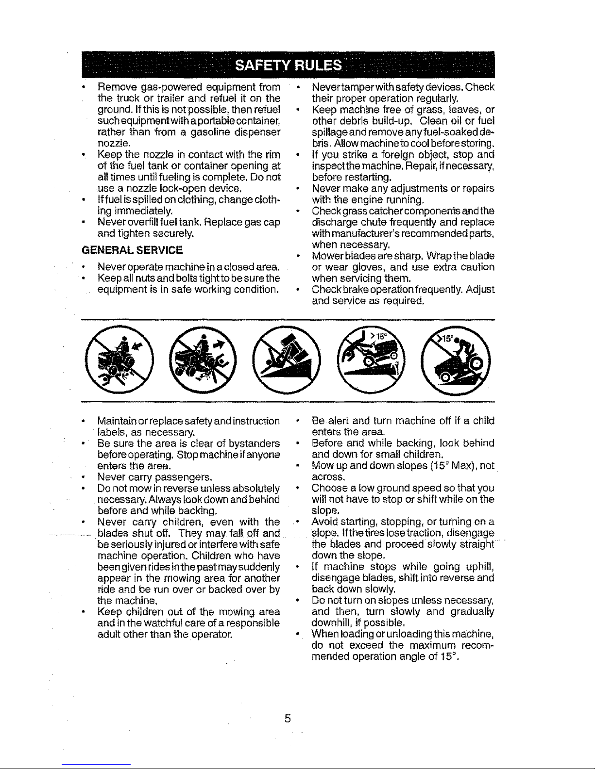
• Mow up and down slopes (!5° Max), not
across.
• Choose a tow ground speed so that you
will not have to stop or shift while on the
slope.
• Avoid starting, stopping, or turning on a
........... lfthe tires losetraction, disengage
the blades and proceed slowly straight ....
down the slope.
• If machine stops while going uphill,
disengage blades, shift into reverse and
back down slowly,
• Do not turn on slopes unless necessary,
and then, turn slowly and gradually
downhill, if possible,
- When Ioadingorunloadingthis machine,
do not exceed the maximum recom-
mended operation angle of 15°.
Page 6
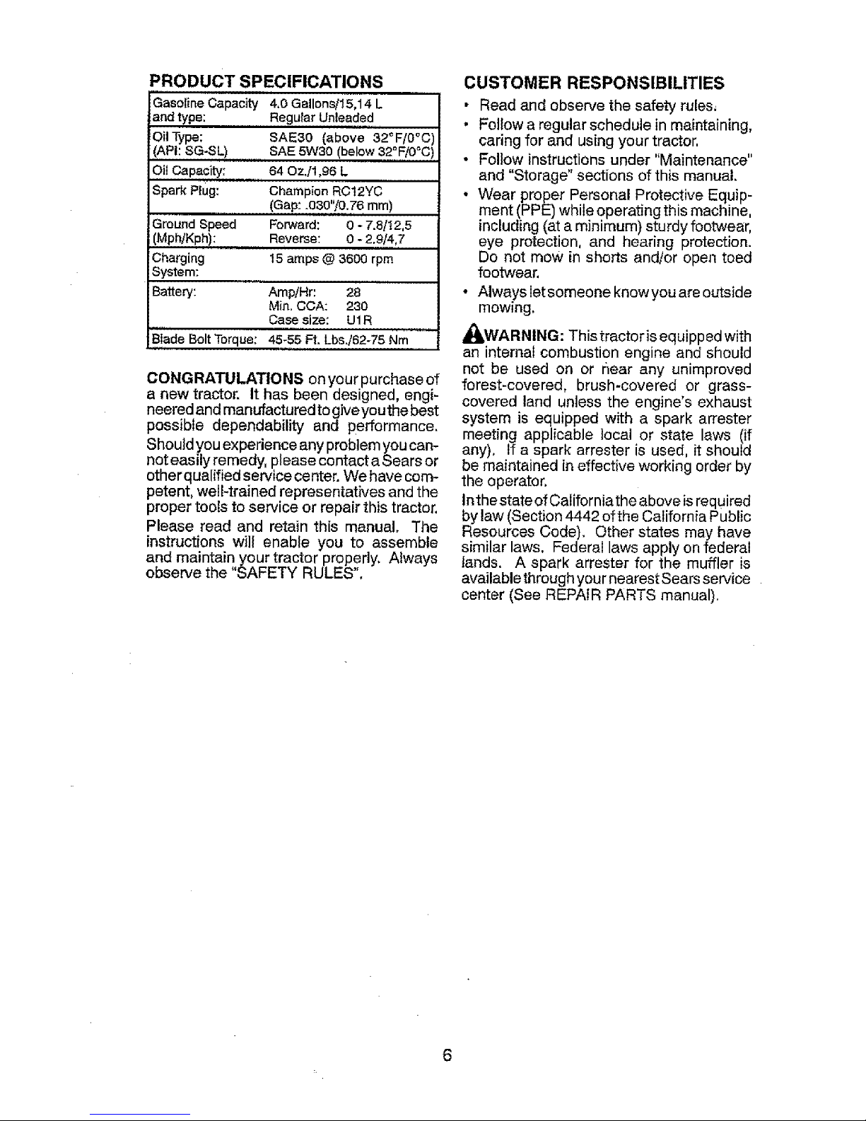
PRODUCT SPECIFICATIONS
Gasoline Capacity 4.0 Gallons/15,14 L
and type Regular Unleaded
OiiType: SAE30 (above 32°F/0°C
,(API: SG-SL) SAE 5W30 (below 32°F/0°C
Oil Capacity: 64 OzJ1,96 L
Spark Plug: Champion RC12YC
(Gap: .030'V0,76 mm)
Ground Speed Forward: 0 - 7.8/} 2,5
(Mph/Kph): Reverse: 0 - 2,9/4,7
Charging 15 amps @ 3600 rpm
System:
Batteq/: Amp!Hr: 28
Min. CCA: 230
Case size: UI R
Blade Bolt Torque: 45-55 Ft. LbsJ62-76 Nm ..... i
CONGRATULATIONS on your purchase of
a new tractor. It has been designed, engi-
neeredand manufactured to giveyouthe best
possible dependability and performance,
Should you experience any problemyou can-
not easily remedy, please contact a Sears or
otherqualffied service center. We have com-
petent, well-trained representatives and the
proper tools to service or repair this tractor.
Please read and retain this manual. The
instructions will enable you to assemble
and maintain your tractor properly. Always
observe the "SAFETY RULES".
CUSTOMER RESPONSIBILITIES
• Read and observe the safety rules,
. Follow a regular schedule in maintaining,
caring for and using your tractor,
• Follow instructions under "Maintenance"
and "Storage" sections of this manual.
• Wear proper Personal Protective Equip-
ment (PPE) while operating this machine,
including (at a minimum) sturdy footwear,
eye protection, and hearing protection.
Do not mow in shorts and/or open toed
footwear,
• Always let someone know you are outside
mowing.
_WARNING: This tractor is equipped with
an internal combustion engine and should
not be used on or r_ear any unimproved
forest-covered, brush-covered or grass-
covered land unless the engine's exhaust
system is equipped with a spark arrester
meeting applicable local or state laws (if
any), If a spark arrester is used, it should
be maintained in effective working order by
the operator.
Inthe state of Californiathe above is required
by law (Section 4442 of the California Public
Resources Code). Other states may have
similar laws. Federal laws apply on federal
lands. A spark attester for the muffler is
available through your nearest Sears service
center (See REPAIR PARTS manual).
6
Page 7
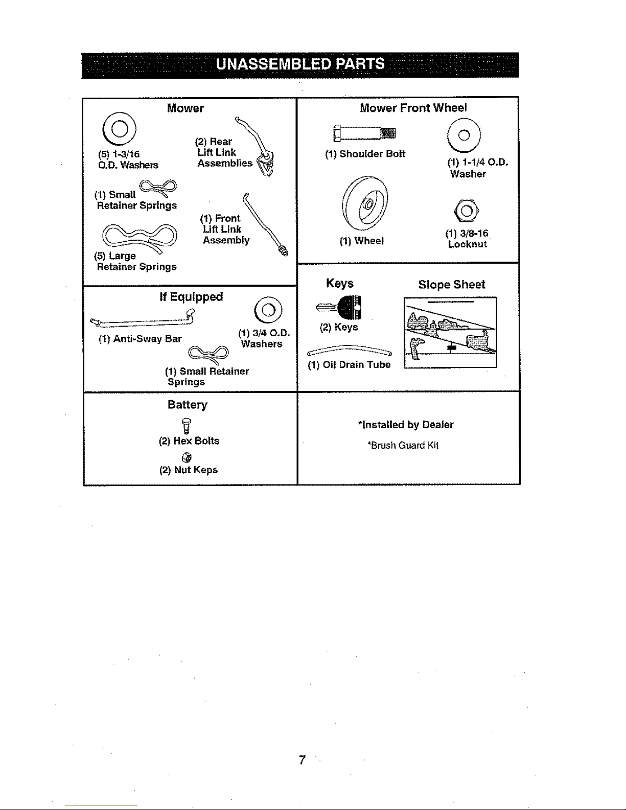
Mower
(2) Rear _
Lift Link _
(5) 1-3/16 Assemblies _-_
O,D. Washers
(1) Small
Retainer Springs
(5) Large
Retainer Springs
(1) Front _
Lift Link \_\
Assembly
If Equipped
(t) Anti-Sway Bar (1) 3/40.D.
Washers
(1) Small Retainer
Springs
Battery
(2) Hex Bolts
(2) Nut Keps
Mower Front Wheel
(1) Shoulder Bolt
(1) 1-1/40.D.
(1) Wheel
Washer
@
(11 3/8-16
Locknut
Slope Sheet
, ,,,,,,,,,,,,
Keys
(2) Keys
(1) Oil Drain Tube
*Installed by Dealer
*Brush GuardKit
.
Page 8
"Yournew tractor has been assembled at the factory with exception of those parts left
unassembled for shipping purposes. To ensure safe and proper operation of your tractor
all parts and hardware you assemble must be tightened securely. Use the correct tools
as necessary to ensure proper tightness,
TOOLS REQUIRED FOR ASSEMBD[
A socket wrench set will make assembly
easier. Standard wrench sizes are listed.
(2) 7/16" wrenches Utility knife
(1) 1/2" wrench Tire pressure gauge
(1) 3/4" wrench Pliers
(1) 3/4" socket w/drive ratchet
(1) 9/16" wrench Flashlight
When right or left hand is mentioned in this
manual,itmeanswhenyou areinthe operating
position (seated behind the steering wheel).
TO REMOVE TRACTOR FROM
CARTON
UNPACK CARTON
• Remove all accessible loose parts and
parts cartons from carton.
• Cut along dotted lines on all four panels
of carton. Remove end panels and lay
side panels flat.
• Remove mower and packing materials.
• Check for any additional loose parts or
cartons and remove.
BEFORE REMOVING TRACTOR
FROM SKID
TO CHECK BATTERY
1. Lifthood to raised position.
NOTE: Ifthis battery is put intoservice after
month and year indicated on label (label is
located between terminals) charge battery
for minimum ofone hour at 6-t 0 amps. (See
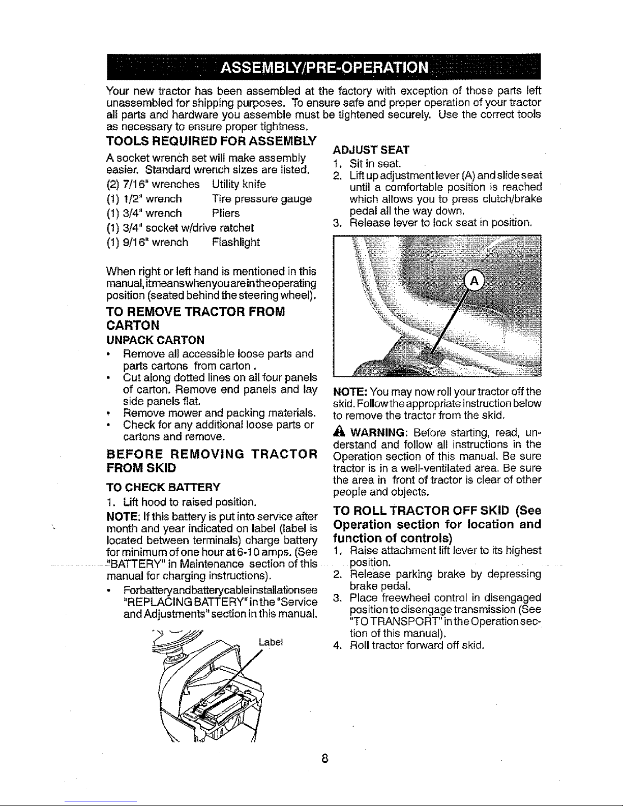
ADJUST SEAT
1. Sit in seat.
2. Lift up adjustment lever (A) and slide seat
until a comfortable position is reached
which allows you to press clutch/brake
pedal all the way down,
3. Release lever to lock seat in position,
NOTE: You may now roll your tractor off the
skid. FoUowthe appropriate instruction below
to remove the tractor from the skid.
AO_WARNING: Before starting, read, un-
derstand and follow all instructions in the
Operation section of this manual. Be sure
tractor is in a welt-ventilated area. Be sure
the area in front of tractor is clear of other
people and objects.
TO ROLL TRACTOR OFF SKID (See
Operation section for location and
function of controls)
1, Raiseattachmentliftleverto itshighest
......................."BATTERY" in Maintenance section of this ....
manual for charging instructions),
° Forbatteryand batterycableinstallationsee
"REPLACING BATTERY" inthe "Service
and Adjustments" section in this manual,
bel
position ......
2. Release parking brake by depressing
brake pedal.
3. Place freewheel control in disengaged
position to disengage transmission (See
"TO TRANSPORT" inthe Operation sec-
tion of this manual),
4. Roll tractor forward off skid.
8
Page 9
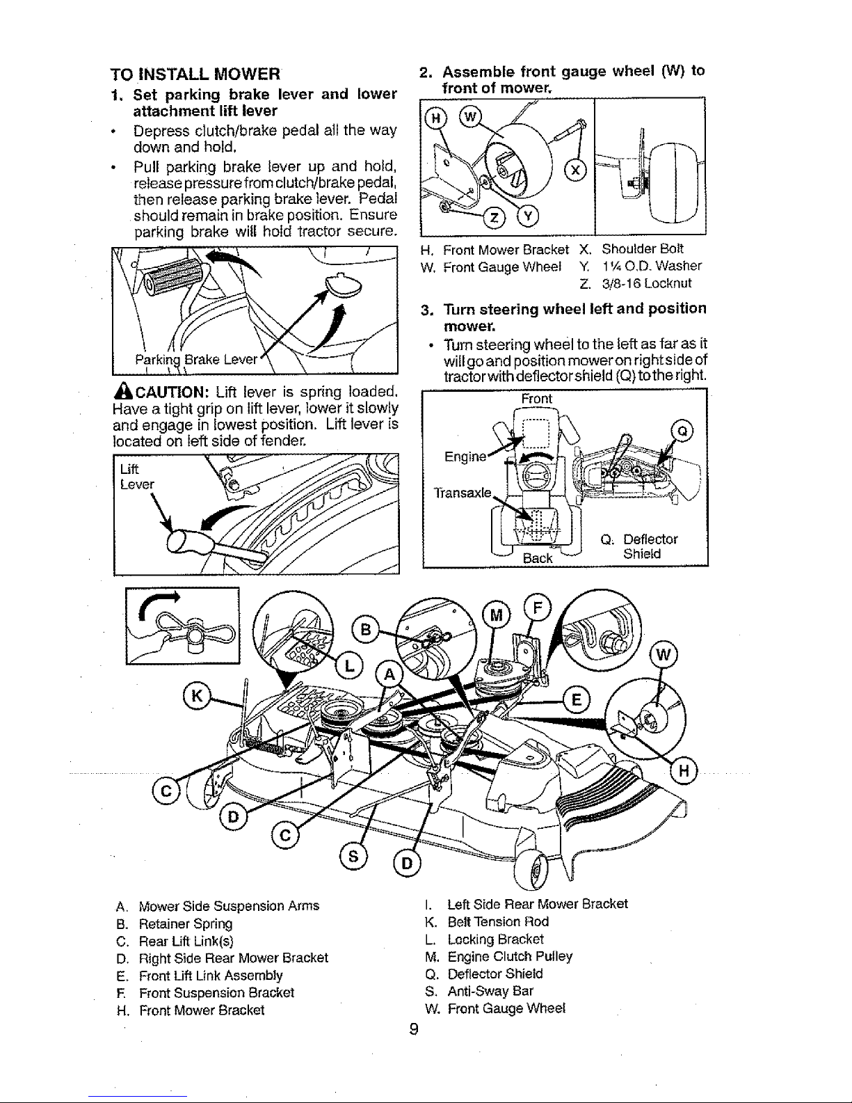
TO INSTALL MOWER
1, Set parking brake lever and lower
attachment lift lever
• Depress clutch/brake pedal all the way
down and hold.
- Pull parking brake lever up and hold,
release pressure from clutch/brake pedal,
then release parking brake lever. Pedal
should remain in brake position. Ensure
parking brake will hold tractor secure.
_IbCAUTION: Lift lever is spring loaded,
Have a tight grip on lift lever, lower it slowly
and engage in lowest position. Lift lever is
located on left side offender.
Lieftver '_k_
2. Assemble front gauge wheel (W) to
front of mower.
H, Front Mower Bracket X, Shoulder Bolt
W. Front Gauge Wheel Y. 1¼ O,D. Washer
Z, 3/8-16 Locknut
3, Turn steering wheel left and position
mower.
• Turn steering wheel to the left as far as it
will go and position moweron rightside of
tractorwith deflectorshield (Q) tothe right.
Front
Q_ Deflector
Shield
A. Mower Side Suspension Arms
B. Retainer Spring
C. Rear Lift Link(s)
D. Right Side Rear Mower Bracket
E, Front Lift Link Assembly
E Front Suspension Bracket
H. Front Mower Bracket
I. Left Side Rear Mower Bracket
K, Belt Tension Rod
L. Locking Bracket
M. Engine Clutch Pulley
Q. Deflector Shield
S, Anti-Sway Bar
W. Front Gauge Wheel
Page 10
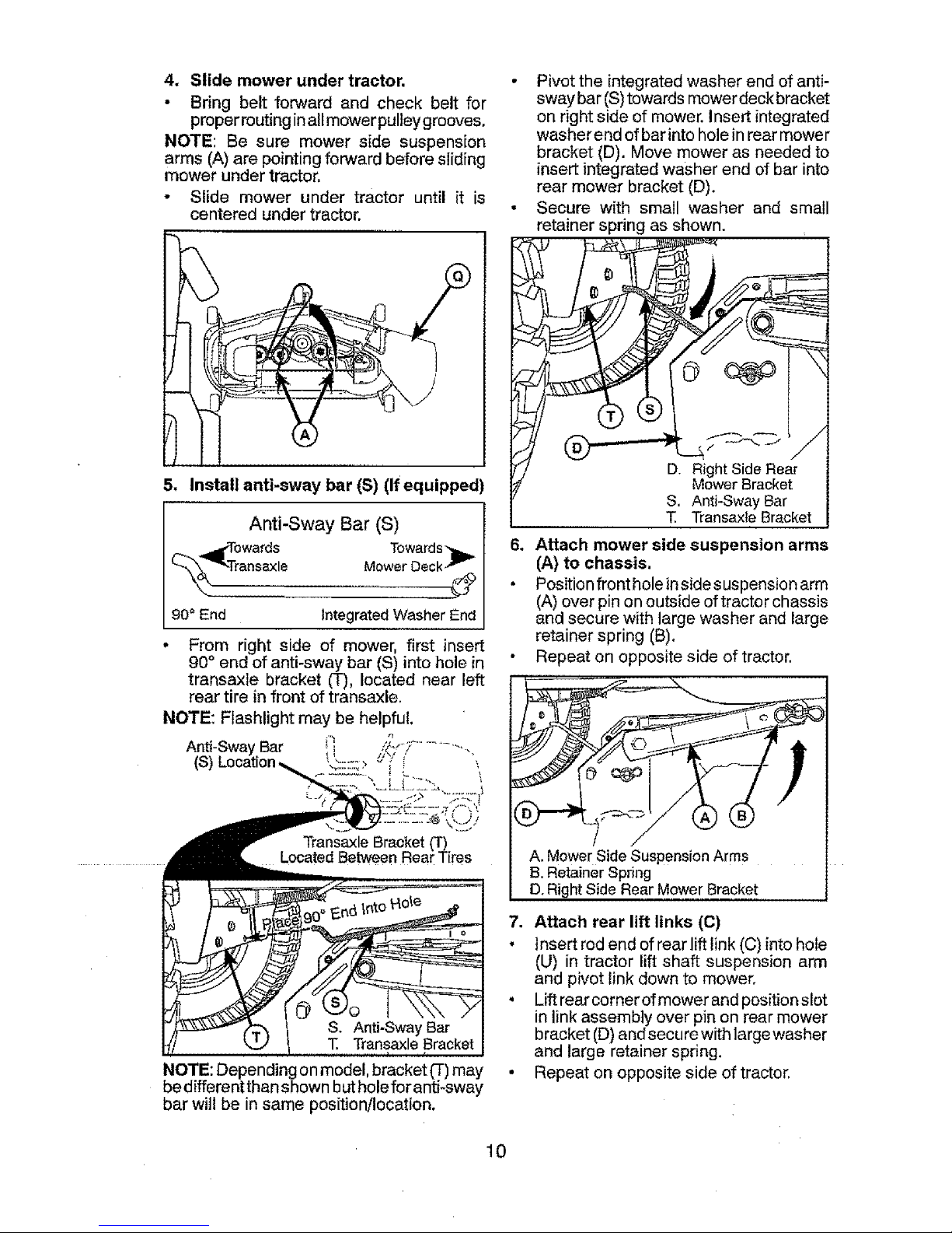
4. Slide mower under tractor.
• Bring belt forward and check belt for
properrouting inalfmower pulteygrooves,
NOTE: Be sure mower side suspension
arms (A) are pointing forward before sliding
mower under tractor,
• Slide mower under tractor until it is
centered under tractor,
• Pivot the integrated washer end of anti-
sway bar (S)towards mowerdeckbracket
on right side of mower,insert integrated
washer end of barinto hole inrear mower
bracket (D). Move mower as needed to
insert integratedwasher end of bar into
rear mower bracket (D).
• Secure with small washer and small
retainer spring as shown.
5. InstaUanti-sway bar (S) (if equipped)
Anti-Sway Bar (S)
Towards "lb,_
Mower Deck-"-
90 ° End Integrated Washer End
From right side of mower, first insert
90° end of anti-sway bar (S) into hole in
transaxle bracket (T), located near left
rear tire in front of transaxle.
NOTE: Flashlight may be helpful.
Bar _, _
Transaxle Bracket
Located Between Real Tires
NOTE: Depending onmodel, bracket _) may
bedifferentthanshown butholeforanti-sway
bar will be in same position/location.
-->
D. Right SideRear
MowerBracket
S. Anti-SwayBar
T, TransaxteBracket
6. Attach mower side suspension arms
(A) to chassis.
• Position front holeinsidesuspension arm
(A)over pinon outside oftractor chassis
and secure with large washer and large
retainer spring (B).
• Repeat on opposite side of tractor.
A. Mower Side Suspension Arms
B.Retainer Spring
D.Right Side Rear Mower Bracket
7. Attach rear lift links (C)
• Insert rod end of rear lift link (C) into hole
(U) in tractor lift shaft suspension arm
and pivot link down to mower.
• Lift rear corner of mower and position slot
in link assembly over pin on rear mower
bracket (D) and secure with large washer
and large retainer spring.
• Repeat on opposite side of tractor.
10
Page 11
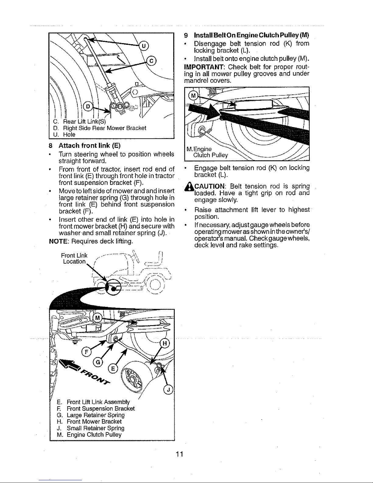
C. Rear Lift Link(S)
D, Right Side Rear Mower Bracket
U. Hole
8 Attach front link (E)
Turn steering wheel to position wheels
straight forward.
• From front of tractor, insert rod end of
front link (E)through front hole intractor
front suspension bracket (F),
• Move toleft side ofmower andand insert
large retainer spring (G) through hole in
front link (E) behind front suspension
bracket (F).
° Insert other end of link (E) intohole in
front mower bracket (H) and secure with
washer and small retainer spring (J).
NOTE: Requires deck lifting.
9 InstallBeltOn EngineClutch Pulley(M)
• Disengage belt tension rod (K) from
locking bracket (L).
, Install beltonto engine clutch pulley (M).
IMPORTANT: Check belt for proper rout-
ing in all mower pulley grooves and under
mandrel covers.
M.Engine
Clutch Pulley
Engage belt tension rod (K) on locking
bracket (L).
_CAUTION: Belt tension rod is spring
loaded, Have a tight grip on rod and
engage slowly.
• Raise attachment lift lever to highest
position.
• Ifnecessary, adjust gauge wheels before
operatingmoweras shown inthe owner's/
operator's manual. Checkgaugewheels,
deck level and rake settings.
E. Front Lift Link Assembly
E Front Suspension 8racket
G. Large Retainer Spring
H. Front Mower Bracket
J. Small Retainer Spring
M. Engine Clutch Pulley
11
Page 12

CHECK TIRE PRESSURE
The tires on your tractor were over-inflated
atthe factory for shipping purposes. Correct
tire pressure is important for best cutting
performance,
• Reducetire pressure toPSIshown ontires.
CHECK DECK LEVELNESS
For best cutting results, mower housing
should be properly leveled. See "TO LEVEL
MOWER" in the Service and Adjustments
section of this manual.
CHECK FOR PROPER POSITION OF
ALL BELTS
See the figures that areshown for replacing
motion and mower blade drive belts in the
Service and Adjustments section ofthis man-
ual. Verify thatthe belts are routed correctly.
CHECK BRAKE SYSTEM
After you learn how to operate your tractor,
checkto see that the brake isoperating prop-
erly, See "TO CHECK BRAKE" inthe Service
and Adjustments section of this manual.
t_CHECKLIST
Before you operate your new tractor, we
wish to assure that you receive the best
performance and satisfaction from this
Quality Product.
Please review the following checklist:
Vt All assembly instructions have been
completed.
No remaining looseparts in carton.
V_ Battery is properly prepared and
charged.
Vf Seat is adjusted comfortably and tight-
ened securely.
_" AIftires are properly inflated. (Forship-
ping purposes, the tires were overinflated
at the factory).
J" Be sure mower deck is properly leveled
side-to-side/front-to-rear for best cutting
results. (Tires must be properly inflated
for leveling).
Check mower and drive belts. Be sure
they are routed properly around pulleys
and inside all belt keepers.
Check wiring, See that all connections
are still secure and wires are properly
clamped.
i/" Before driving tractor, besure freewheel
control is in "transmission engaged"
position (see "TO TRANSPORT" in the
Operation section of this manual),
While learninghowto useyourtractor, payex-
tra attention tothe following importantitems:
t/( Engine oil is at proper level.
J" Fueltankis filledwithfresh, clean, regular
unleaded gasoline.
tif Become familiar with all controls, their
location and function, Operate them
before you start the engine,
t/" Besure brake system isin safeoperating
..........................................................................................................condition.
Be sure Operator Presence System and
Reverse Operation System (ROS) are
working properly (Seethe Operation and
Maintenance sections in this manual).
J" It is importantto purge the transmission
before operating your tractor for thefirst
time. Follow properstartingand transmis-
sion purginginstructions(See'70 START
ENGINE"and "PURGETRANSMISSION"
inthe Operation section of thismanual).
12
Page 13

These symbols may appear on your tractor or in literature supplied with the product.
Learn and understand their meaning,
R N H L I',,I
REVERSE NEUTRAL HIGH LOW CHOKE FAST SLOW
ENGINE OFF REVERSE ENGINE ON ENGINE START PARKING BRAKE MOWER HE[GNT
OPERATION
SYSTEM (ROe)
CRUISE CONTROL
IGNITION SWJTCH
MOWER LiFT
,_ ;i;
CLUTCH/BRAKE
LIGHTS ON FUEL BATTERY REVERSE FORWARD
PEDAL
ATTACHMENT ATTACHMENT OANGER_ KEEP HANDS
CLUTCH DISENGAGED CLUTCH ENGAGED AND FEET AWAY
FREE WHEEL
(Automatic Models only)
®@@@@
KEEP AREA CLEAR SLOP_E HAZARDS
(SEE SAFETY RULES SECTION)
DANGER indicates a hazard which, if not avoided,
will result in death or serious injury.
WARNING indicates a hazard which, if not avoided,
could result in death or serious injury.
CAUTION indicates a hazard which, if not avoided,
might result in minor or moderate injury.
CAUTION when used without the alert symbol,
indicates a situation that could result in damage
to the tractor and/or engine.
Failure to follow instructions
could result in serious injury or
death. The safety alert symbol ,,_,_,_,i_,,.
is used to identify safety inform-
ation about hazards which can Y_,
result in death, serious injury
and/or property damage.
HOT SURFACES indicates a hazard which,
if not avoided, could result in death, serious injury
andlor property damage.
FIRE indicates a hazard which, if not avoided,
could result in death, serious injury andtor
property damage.
13
Page 14

KNOW YOUR TRACTOR
READ THIS MANUAL AND SAFETY RULES BEFORE OPERATING YOUR TRACTOR
Compare the i_lustrationswithyour tractor to familiarize yourself withthe locations of
various controls and adjustments. Save this manual for future reference.
Our tractors conform to the applicable safety standards of the
American National Standards Institute.
(A) ATTACHMENT LIFT LEVER- Used to
raise and lower the mower or other attach-
ments mounted to your tractor.
(B) BRAKE PEDAL- Used for braking the
tractor and starting the engine.
(C) PARKING BRAKE- Locksclutchibrake
pedal into the brake position.
(D) THROTTLE CONTROL- Used to con-
tro] engine speed,
..........................(E) ATTACHMENT CLUTCH SWITCH
- Used to engagethe mowerblades, orother
attachments mounted to your tractor.
(F) IGNITION SWITCH - Used for starting
and stopping the engine.
(G) REVERSE OPERATION SYSTEM
(ROS) "ON" POSITION- Allows operation
of mowerorother poweredattachmentwhile
in reverse.
(H) LIGHT SWITCH - Turns the headlights
on and off,
(J) CRUlSE CONTROL LEVER- Used to set
forward movement of tractor at desired speed
without holding the forward drive pedal.
(K) FORWARD DRIVE PEDAL- Used for
forward movement of tractor.
(L) REVERSE DRIVE PEDAL- Used for
reverse movement of tractor.
(M) FREEWHEELCONTROL- Disengages
transmission for pushing or slowly towing
the tractor with the engine off.
(N) CHOKE CONTROL- Used when starting
a cold engine,
(P) SERVICE REMINDER / HOUR METER
- Indicates when service is required for the
engine and mower.
4
Page 15

The operation of any tractor can result in foreign objects thrown into the
eyes, which can result in severe eye damage. Always wear safety glasses
or eye shields while operating your tractor or performing any adjustments
or repairs. We recommend standard safety glasses or a wide vision safety
mask worn over spectacles.
HOW TO USE YOUR TRACTOR
TO SET PARKING BRAKE
Your tractor is equipped with an operator
presence sensing switch, When engine is
running, any attempt bythe operatorto leave
the seat without first settingthe parking brake
will shut off the engine.
1. Depress brakepeda] (B)allthewaydown
and hold,
2. Pull parking brake lever (C) up and hold,
release pressure from brake pedal (B),
then release parking brake lever. Pedal
should remain in brake position, Make
sureparking brakewill holdtractorsecure,
HI................
STOPPING
MOWER BLADES -
• To stop mower blades, move attachment
clutch controlto disengaged position (r_).
ENGINE -
• Move throttle control (D) to slow position.
NOTE: Failure to move throttle control
to slow position and allowing engine to
idle before stopping may cause engine to
"backfire".
• Turn ignition key (F) to "STOP" position
andremove key, Always removekeywhen
leavingtractorto prevent unauthorizeduse.
• Never use choke to stop engine.
IMPORTANT: Leaving the ignition switch in
any positionotherthan "STOP"will causethe
battery to discharge and go dead,
NOTE: Under certainconditions when tractor
is standing idle with the engine running, hot
engine exhaust gases may cause "brown-
ing" of grass, To eliminate this possibility,
always stop engine when stopping tractor
on grass areas.
_,CAUTtON: Always stop tractor com-
pletely, as described above, before leaving
the operator's position.
TO USE THROTTLE CONTROL (D)
Always operate engine at full speed (fast).
• Operating engine at less than full speed
(fast) reduces engine's operating effi-
ciency.
, Full speed (fast) offers the best mower
performance.
(1_1) Attachment (1"_) Attachment
Clutch Control Clutch Control
"Engaged .... Disengaged"
GROUND DRIVE -
• Tostop ground drive, depress brake pedal
all the way down.
IMPORTANT: Forward and reverse drive
pedals return to neutral position when not
depressed.
TO USE CHOKE CONTROL (N)
Use choke control whenever you are start-
ing a cold engine. Do not use to start a
warm engine.
• Toengage choke control, pull knob out.
Slowly push knob in to disengage.
15
Page 16

.........TO MOVE FORWARD AND BACKWARD .........The cutting height range is approximately
The direction and speed of movement is
controlled by the forward and reverse drive
pedals.
1. Start tractor and release parking
brake.
2. Slowly depress forward(K) or reverse(L)
drive pedal to begin movement. Ground
speed increases the further down the
pedal is depressed.
TO USE CRUISE CONTROL
The cruise control feature can be used for
forward travel only.
SYSTEM CHARACTERISTICS
The cruise control should only be used
while mowing or transporting on relatively
smooth, straight surfaces. Other conditions
such astrimming at slow speeds may cause
the cruise control to disengage. Donot use
...................the cruise control on slopes, rough tertian
or while trimmimg or turning.
• With forward drive pedal depressed to
desired speed, pull cruise control lever
(J) up and hold while lifting your foot off
the pedal, then release the lever,
Todisengage the cruise control, depressthe
brake pedal, tap on forward drive pedal or
push the cruise control lever down.
TO ADJUST MOWER CUTTING HEIGHT
The position ofthe attachment lift lever (A)
determines the cutting height.
• Put attachment liftlever in desired cutting
..............................height slot.
• Slide pointer tab (T) to desired cutting
heightas areminderfor nexttimeyou mow.
1"to 4". The heights are measured from the
groundtothe bladetipwith theengine not run-
ning, These heights areapproximateand may
vary depending upon soil conditions, height
of grass and types of grass being mowed.
• The average lawn should be cut to ap-
proximately 2-1/'2" during the cool season
and to over 3" during hot months, For
healthier and better looking lawns, mow
often and after moderate growth.
, For best cutting performance, grass over
6" in height should be mowedtwice. Make
the first cut relatively high; the second to
desired height.
TO ADJUST GAUGE WHEELS
Gauge wheels are properly adjusted when
they are slightly offthe ground when mower
is at the desired cutting height in operating
position, Gauge wheels then keep the deck
in proper position to help prevent scalping
in most terrain conditions.
NOTE: Adjust gauge wheels with tractor on
a flat level surface.
1. Adjust mower to desired cutting height
(See "TO ADJUST MOWER CUTTING
HEIGHT" in this section of manual).
2. With mower in desired height of cut posi-
tion, gauge wheels should be assembled
so they are slightly offthe ground, install
gauge wheel in appropriate hole. Tighten
securely.
3. Repeat for all, installing gauge wheel in
same adjustment hole.
TO OPERATE MOWER
Your tractor is equipped with an operator
presence sensing switch.Any attemptbythe
operator to leave the seat with the engine
running and the attachment clutch engaged
will shut off the engine, You must remain
fully and centrally positioned in the seat to
prevent the enginefrom hesitating or cutting
offwhen operating yourequipment onrough,
rolling terrain or hills.
1. Select desired height of cut with attach-
ment lift lever,
2. Start mower blades by engaging attach-
ment clutch control.
16
Page 17

TO STOP MOWER BLADES
Disengage attachment clutch control
d_ILCAUTION: Do not operate the mower
without either the entire grass catcher, on
mowers so equipped, orthe deflector shield
(S) in place.
REVERSE OPERATIONSYSTEM (ROS)
Your tractor is equipped with a Reverse
Operation System (ROS). Any attempt by
the operator totravel inthe reverse direction
with the attachment clutch engaged will shut
off the engine unless ignition key is placed
in the ROS "ON" position,
_IbWARNING: Backing up with the at-
tachment clutch engaged while mowing is
strongly discouraged. TurningtheROS"ON",
TO OPERATE ON HILLS
_kWARNING: Do not drive up or down
hills with slopes greater than 15°and de not
drive across any slope. Use the slope guide
provided at the back of this manual.
• Choose the slowest speed before starting
up or down hills,
• Avoid stopping or changing speed on
hills.
• if stopping is absolutely necessary, push
brake pedal quickly to brake position and
engage parking brake.
• To restart movement, slowly release park-
ing brake and brake pedal.
• Slowly depress appropriate drive pedal to
slowest setting.
• Make all turns slowly.
TO TRANSPORT
When pushing or towing your tractor, be
sure to disengage transmission by placing
freewheel control infreewheeling position,
Free wheel control is located at the rear
drawbar of tractor.
• Raise attachment lift to highest position
with attachment lift control,
• Pullfreewheel control out andintothe slot
andrelease soit is held inthe disengaged
to allow reverse operation with the attach- position.
meat clutch engaged, should only be done Do not push or tow tractor at more than
.............when the operator decides it is necessary to ...... two (2) MPH.
reposition the machine with the attachment
engaged. Do not mow in reverse unless • To reengagetransmission, reverse above
3.
4,
• 5,
absolutely necessary.
USING THE REVERSE OPERATION SYSTEM
Only use ifyou are certain no children orother
bystanders will enter the mowing area.
1. Depress brake pedal all the way down.
2. With engine running, turn ignition key
counterclockwise to ROS "ON" position,
Look down and behind before and while
backing.
Slowly depress reverse drive pedal to
start movement,
When use of the ROS is no longer
needed, turn the ignition key clockwise
to engine "ON" position.
ROS "ON" Position
Engine "ON" Position
(Normal Operating)
procedure.
NOTE: To protect hood from damage when
transporting yourtractoron atruckoratrailer,
besurehood isclosed and secured totractor. ........
Use an appropriate means of tying hood to
tractor (rope, cord, etc.),
TOWING CARTS AND OTHER ATTACH-
MENTS
Tow only the attachments that are recom-
mended by and comply with specifications
of the manufacturer of your tractor, Use
common sense when towing. Too heavy of
aload, while on a slope, is dangerous. Tires
can lose traction with the ground and cause
you to lose control of your tractor,
17
Page 18

SERVICE REMINDER!HOUR METER
Service remindershows the total number of
hours the engine hasrunand indicateswhen
theengine or mower needs servicing. After
every 50 hours of operation the oil can icon
will stay onfor2 hours or untila manual reset
occurs. To reset the display manually turn
the ignitionswitch to the on position,then
the off position five times (1 second on, 1
second off). To service engine and mower,
see the Maintenance section of this manual.
Note: Service reminder runs when the
ignition key is in any position but "STOP",
For accurate reading, be sure key remains
in the "STOP" position when engine is not
running.
BEFORE STARTING THE ENGINE
CHECK ENGINE OIL LEVEL
Theengine inyour tractor has beenshipped,
from the factory, already filled with summer
weight oil.
1. Check engine oil with tractor on level
ground.
2. Unthread and remove oilfillcap/dipstick;
wipe oil off. Reinsert the dipstick intothe
tube and rest oil fill cap on the tube. Do
notthreadthe capontothetube. Remove
and read oil level. If necessary, add oil
.............. until "FULL' markon dipstick is reached.
Do not overfill
• For cold weather operation you should
change oil for easier starting (See the oil
viscosity chart inthe Maintenance section
of this manual),
• Tochange engine oil, seethe Maintenance
section in this manual.
ADD GASOLINE
• Fill fuel tankto bottom offilfer neck, Do not
overfill. Usefresh, clean, regular unleaded
gasoline with a minimum of 87 octane,
(Use of leaded gasoline will increase
..............................carbon andleadoxidedeposits and reduce
valve life). Do not mix oil with gasoline.
Purchase fuel inquantitiesthat canbe used
within 30 days to assure fuel freshness.
_CAUTION: Wipe offanyspitled oilorfuel.
Do not store, spill or use gasoline near an
open flame.
IMPORTANT: When operating in tempera-
tures below32°F/0°C, usefresh, clean winter
grade gasoline to help ensure good cold
weather starting.
CAUTION: Alcohol blended fuels (called
gasohol or using ethanol or methanol) can
attract moisture which leads to separation
andformation ofacids during storage, Acidic
gas candamagethe fuelsystem of anengine
while in storage. Toavoid engine problems,
the fuel system should be emptied before
storage of 30 days or longer, Drain the gas
tank, start the engine and let itrun until the
fuel lines and carburetor are empty. Use
freshfuel nextseason. See Storage Instruc-
tions for additional information, Never use
engine or carburetor cleaner products inthe
fuel tank or permanent damage may occur.
RESERVE FUEL VALVE OPERATION
1. Raise seat to access reserve fuel valve.
2. In normal operation, valve should be set
to primary (as shown inview)
3. If tractor runs out of fuel, rotate valve
handle to reserve.
4. Drive tractor to be refueled,
5. After refueling, return valve to primary
position,
Reserve
FuelValve
@
Primary
TO START ENGINE
When starting the engine for the first time or
if the engine has run out of fuel, it will take
extra cranking time to move fuel from the
tank to the engine.
1. Be sure freewheel control is inthe trans-
mission engaged position.
2. Sit on seat in operating position, depress
brake pedal and set parking brake.
3. Move attachment clutch to disengaged
position.
4. Move throttle control to fast position
5, Pull choke control out for a cold engine
start attempt. For a warm engine start
attempt the choke control may not be
needed.
NOTE: Before starting, read the warm and
cold starting procedures below.
18
Page 19

6, Insert key into ignition and turn key
clockwise to start position and release
keyas soon as engine starts. Do not run
starter continuously formorethan fifteen
seconds per minute. Ifthe engine does
not start after several attempts, push
choke control in, wait afew minutes and
try again. If engine still does not start,
pull the choke control out and retry.
WARM WEATHER STARTING
(50°F (10°C) and above)
7. When engine starts, slowly push choke
control in until the engine begins to run
smoothly. ]f the engine starts to run
roughly,pullthe choke control out slightly
for a few seconds and then continue to
push the control in slowly.
° The attachments and ground drive
can now be used, tf the engine does
not accept the load, restart the engine
and allow itto warm upfor one minute
using the choke as described above.
COLD WEATHER STARTING
(50°F (10°C) and below)
7. When engine starts, slowly push choke
control in until the engine begins to run
smoothly, Continue to push the choke
control insmall steps allowing the engine
to accept small changes in speed and
load, until the choke control is fully in.
If the engine starts to run roughly, pull
the choke control out slightly for a few
seconds and then continue to push the
control in slowly. This may require an
engine warm-up period from several
seconds to several minutes, depending
on the temperature.
AUTOMATIC TRANSMISSION 'WARM UP
Before driving the unit in cold weather, the
transmission should be warmed up as fol-
lows:
.........1. Be sure the tractor is on level ground.
2. Release the parking brake and let the
brake slowly returnto operating position.
3. Allow one minute for transmission to
warm up, This can be done during the
engine warm up period.
• The attachments can be used during
the engine warm-up period after the
transmission has been warmed up
and may require the choke control be
pulled out slightly,
NOTE: Ifatahigh altitude (above 3000 feet)
or in cold temperatures (below 32°F (0°C))
the carburetor fuel mixture may need to be
adjusted for best engine performance (see
"TOADJUSTCARB URETOR"inthe Service
and Adjustments section of this manual). 19
PURGE TRANSMISSION
_IbCAUTION: Neverengage or disengage
freewheel leverwhile the engine is running,
Toensure properoperation andperformance,
it is recommended that the transmission be
purged before operating tractor for the first
time.This procedure will remove anytrapped
air insidethe transmission which may have
developed during shipping of your tractor.
IMPORTANT: Should your transmission
require removal for service or replacement,
itshould bepurged after reinstallation before
operating the tractor.
!. Place tractor safely on a level surface -
that is clear of objects and open - with
engine off and parking brake set.
2. Disengage transmission by placing
freewheel control in disengaged position
(See "TO TRANSPORT" in this section
of manual).
3. Sitting in the tractor seat, start engine.
After the engine isrunning, move throttle
control to slow position. Disengage park-
ing brake.
,d_,CAUTION: At any time, during step 4,
there may be movement ofthe drive wheels,
4, Depressforward drivepedalto full forward
position and holdfor five (5)seconds and
release pedal, Depress reverse drive
pedal to full reverse position and hold
for five (5) seconds and release pedal.
Repeat this procedure three (3) times.
5, Shutoff engine and set parking brake.
6. Engage transmission by placing free-
wheel control in engaged position (See
"TO TRANSPORT" in this section of
manual).
7. SiRing in the tractor seat, start engine.
After the engine is running, move throttle
control to half (1/2) speed. Disengage
parking brake.
8. Drive tractor forward for approximately
five feet then backwards for five feet.
Repeat this driving procedure three
times.
Your transmission is now purged and now
ready for normal operation.
Page 20

MOWING TIPS
• Tire chains cannot be used when the
mower housing is attached to tractor.
- Mower should be properly leveled for best
mowing performance. See "TO LEVEL
MOWER HOUSING" inthe Service and
Adjustments section of this manual.
• The left hand side of mower should be
used for trimming.
- Ddveso that clippings are discharged onto
the areathat has already been cut. Have
the cut areato the right ofthe tractor. This
will result in a more even distribution of
clippings and more uniform cutting.
• When mowingIarge areas, start byturning
to the right sothat clippings will discharge
away from shrubs, fences, driveways,
etc. After one ortwo rounds, mow inthe
opposite direction making left hand turns
untilfinished.
• If grass is extremely tail, it_should be
mowed twice to reduce load and possible
fire hazard from dried clippings. Make
first cut relatively high; the second to the
desired height,
• Do not mow grass when it is wet. Wet
grass will plug mower and leave undesir-
able clumps. Allow grass to dry before
mowing.
• Always operate engine at full throttle
when mowing to assure better mow-
ing performance and proper discharge
of material. Regulate ground speed by
selecting a low enough speed to give the
mower cutting performance aswell as the
quality of cut desired.
• When operating attachments, select a
ground speed that willsuit the terrain and
give best performance of the attachment
being used.
2O
Page 21

MAINTENANCE ............
SCHEDULE
Check Bra,ke Operation .......
Check Tire Pressure
Check Operator Presence & ROe Sys,!,ems
A Checkfor Loose Fasleae_*s.,,
C CheckJRepIace Mower Blades
T Lubrication Chart
0 Cheek Batter/Level
R C_ean Battery and Terminals
Clean Debris Off Steering Plate
Check T_'ansaxte Coo.!i,ng
Check Mower Levelness
Check V=Belts
i,,i,, lllul ,
Check Enpine Oil Level
Change Engine Oil with q,!l filter}
NE Change En_ineO!,l,(witheeloilfilter)C_ean Air Fi!!er
G c!ean Air Screen
I Inspect MutiledSpark ,Attester
N Replace O_.!!,Filter (if equipped)
E Clear_ Engirte Cooling Fins
Replace Spark Plug ....
Replace Air Filter Paper Cartridge
Replace Fuel Filter,
B£FOR_ EVERY
EACH 8
USE HOURS
V
v'
,,,,,,,,,,,,
EVERY _tERY
25 50
HOURS HOURS
is"
v;
v"
v'
EVERV
180
HOURS
i,"
I_V_RY BEFORE
S_.ASON STOeAGE
v"
v"
v"
_s
v"
.... V' v"
,,, V _
GENERAL RECOMMENDATIONS
The warranty on this tractor does not cover
items that have been subjected to operator
abuse or negligence. To receive full value
from the warranty, operator must maintain
tractor as instructed in this manual.
Some adjustments will need to be made pe-
riodically to properly maintain your tractor.
At least once a season, check to see if
you should make any of the adjustments
described in the Service and Adjustments
section of this manual.
...............- At least once a year you should replace
the spark plug, clean or replace air filter,
and check blades and belts for wear. A
new spark plug and clean air filter assure
proper air-fuel mixture and help your en-
gine run better and last longer.
BEFORE EACH USE
1. Check engine oil level,
2. Check brake operation.
3, Check tire pressure,
4. Check operator presence and
Roe systems for proper operation.
5, Check for loose fasteners.
LUBRICATION CHART
(T_Spindle__--_l_ O Spindle
Zerk __,_ Zerk
0_Frontf L-S#}_*. "-_ [_'d) FrontWheet
Wheel __z__'_4FL Bearing Zerk
rdeanng .-"1_%{_ I
Zerk /..KJ [ J.J "%--,,.
Steering/4__9_.., "@ Engined)
Sector rl _ t_
Gear I t q_ir:;_= I 1\ ......
Teeth _ \@ Mandrel
Zerks
OGeneral Purpose Grease
@Refer to Maintenance"ENG] NE" Section.
IMPORTANT: Do not oil or greasethe pivot
points which have special nylon bearings.
Viscous lubricants will attract dust and dirt
thatwill shorten thelife of the self-lubricating
bearings. Ifyou feel they must be lubricated,
use only a dry, powdered graphite type lu-
bricant sparingly,
21
Page 22

TRACTOR
Always observesafety ruleswhen performing
any maintenance.
BRAKE OPERATION
Iftractor requires more than five (5) feet to
stop at highest speed in highest gear on a
level, dry concrete or paved surface, then
brake must be serviced. (See "TO CHECK
BRAKE" in the Service and Adjustments
section of this manual).
TIRES
• Maintain proper air pressure in all tires
(See PSi on tires).
• Keep tires free of gasoline, oil, or insect
control chemicals which can harm rubber.
• Avoid stumps, stones, deep ruts, sharp
objects and other hazards that maycause
tire damage.
NOTE: To seat tire punctures and prevent
flat tires due to slow leaks, tire sealant may
be purchased from your local parts dealer.
Tire sealant also prevents tire dry rot and
corrosion.
OPERATOR PRESENCE SYSTEM AND
REVERSE OPERATION SYSTEM (ROS)
Be sure operator presence and reverse
operation systems are working properly. If
your tractor does notfunction as described,
repair the problem immediately.
• The engine should not start unless the
brake pedal is fully depressed, and the
attachmentclutch control is in the disen-
gaged position.
CHECK OPERATOR PRESENCE
SYSTEM
• When the engine is running, any attempt
by the operator to leave the seat without
first setting the parking brake should shut
off the engine.
• When the engine is running and the at-
tachment clutch is engaged, any attempt
.....................................by the operator to leave the seat should ....
shut offthe engine.
• The attachment clutch should never oper-
ate unless the operator is in the seat.
ROS'ON" Position Engine"ON" Position
(NormalOperating)
CHECK REVERSE OPERATION (ROS)
SYSTEM
• Whenthe engine isru,nningwiththe ignition
switch inthe engine' ON" position and the
attachment clutch engaged, any attempt
bythe operator toshift into reverse should
shut off the engine.
- When theengineis running withthe ignition
switch in the ROS "ON" position and the
attachment clutch engaged, any attempt
bythe operator to shift into reverseshould
NOT shut off the engine.
BLADE CARE
Forbest results mower blades must besharp.
eplace worn, bent or damaged blades.
CAUTION: Use only areplacement blade
approved bythe manufacturerof yourtractor.
Using a blade not approved by the manu-
facturer of your tractor is hazardous, could
damage your tractor and voidyour warranty.
BLADE REMOVAL
1. Raise mower to highest positionto allow
access to blades.
NOTE: Protect your hands with gloves and!
or wrap blade with heavy cbth,
2. Remove blade bolt by turning counter-
clockwise.
3. install new blade with stamped "THIS
SIDE UP" facing deck and mandrel as-
semb[y.
IMPORTANT: To ensure proper assembly,
center hole in btade must align with star on
mandrel assembly,
4. Install and tighten blade bolt securely
(45-55 Ft. Lbs. torque/62-75 Nm).
IMPORTANT: Special blade bolt is heat
treated.
Mandrel
Assembly
Center Hol;_-I_.!,_
BATTERY
Yourtractorhas a battery chargingsystem
whichissufficient for normal use. However,
periodicchargingof the battery withan au-
tomotivechargerwillextend its life.
• Keep batteryand terminals dean.
• Keepbattery bolts tight.
• Keepsmall vent holesopen.
- Recharge at 6-10 amperes for 1 hour,
NOTE: The original equipment battery on
your tractor is maintenance free, Do not
attempt to open or remove caps or covers.
Adding or checking level of electrolyte is
not necessary.
22
Page 23

TO CLEAN BATTERY AND TERMINALS
Corrosion and dirt on the battery and termi-
nals can cause the battery to "leak" power,
1, Remove terminal guard.
2, Disconnect BLACK battery cable first
then RED battery cable and remove
battery from tractor.
3, Rinse the battery with plain waterand dry,
4, Clean terminals and battery cable ends
with wire brush until bright,
5. Coat terminals with grease or petroleum
jelly.
6. Reinstall battery (See "REPLACING
BATTERY" in the SERVICE AND AD-
JUSTMENTS section of this manual).
TRANSAXLE MAINTENANCE
The transmission fan and cooling fins should
be kept clean to assure proper cooling, Do
not attemptto clean fan ortransmission while
engine is running or while the transmission
is hot. To prevent possible damage to seals,
do not use high pressure water or steam to
clean transaxte.
• Inspect cooling fan to be sure fan blades
are intact and dean.
• ]nspectcoolingfinsfordirt, grassclippings
and other materials. To prevent damage to
seals, do not use compressed air or high
pressure sprayer to clean cooling fins.
TRANSAXLE PUMP FLUID
The transaxte was sealed at the factory and
fluid maintenance is not required for the life
of the transaxle. Should the transaxle ever
leak or require servicing, contact your near-
est Sears or other qualified service center.
V-BELTS
Check V-belts for deterioration and wear after
! 00 hours of operation and replace if neces-
sary. The belts are not adjustable. Replace
belts if they begin to slip from wear.
ENGINE
LUBRICATION
Only use high quality detergent oil rated with
..............AP] service classification SG-SL Selectthe
oil's SAE viscosity grade according to your
expected operating temperature,
£AE VISCOSITY GRADES
c ._¢ _2o q0 0 _ 2O _ 4o,
_=M P_R AT_E RAN_ ANTIC_ATEQ 8_=O RE' N_'T O]L C_'_G E
NOTE: Although multi-viscosity oils (5W30,
t 0W30 etc,) improvestarting in coldweather,
they wii! result in increased oil consumption
when used above 32°F/0°C, Check your
engine oil level more frequently to avoid
possible engine damage from runninglow
on oil.
23
Change the oil after every 50 hours of
operation or at least once a year ifthe tractor
is not used for 50 hours in one year.
Check the crankcase oil level before starting
the engine and after each eight (8) hours
of operation. Tighten oil till cap/dipstick
securely each time you check the oil level.
TO CHANGE ENGINE OIL
Determine temperature range expected
before oil change. All oil must meet API
service classification SG-SL,
1, Ensure tractor is on level surface,
2. Oil will drain more freely when warm.
3, Catch oil in a suitable container,
4. Remove oil fill cap/dipstick. Be careful
not to allow dirt to enter the engine when
changing oil
5. Install the drain tube onto the valve.
6. Open drain valve by using a 10ram
wrench turning counterclockwise,
Oil Drain Valve
To Close
Drain Tube
7. After oil has drained completely, close
the drain valve turning clocl_ise. Use the
10mm wrench to apply a small amount
of torque to keep it closed. Do not over
tighten.
8. Remove the drain tube and store in a
safe place.
9. Refill engine with oil through oil flu dipstick
tube, Pour slowly. Do not overfill. For
approximate capacity see "PRODUCT
SPECIFICATIONS" section of this
manual.
10.Use gauge on oil fill cap/dipstick for
checking level, insert dipstick into the
tube and rest the oil fill cap on the tube.
Do notthread the cap onto the tube when
taking reading. Keep oil at "FULI_' fine
on dipstick. Tighten cap onto the tube
securely when finished.
ENGINE OIL FILTER
Replace the engine oil filter every season or
every other oil change if the tractor is used
more than 100 hours in one year.
Page 24

AIR FILTER
Your engine will not run properly using a
dirty air filter. Service air cleaner more often
under dusty conditions,
CLEAN AIR SCREEN
Air screen must be kept free of dirt and chaff
to prevent engine damage from overheating.
Clean with awire brush or compressed airto
remove dirt and stubborn dried gum fibers.
ENGINE COOLING SYSTEM
To ensure proper cooling, make sure the
grass screen, cooling fins, and other exter-
nal surfaces of the engine are kept clean
at all times,
Every 100 hours of operation (more often
under extremely dusty, dirty conditions),
removethe blower housing and other coofing
shrouds. Clean the cooling fins and external
surfaces as necessary. Ensure the cooling
shrouds are reinstalled.
NOTE: Operating the engine with a blocked
grass screen, dirty or plugged cooling fins,
and!or cooling shrouds removed will cause
engine damage due to overheating.
MUFFLER
Inspect and replace corroded muffler and
sparkarreste r(if equipped)as itcouIdcreate
a fire hazard and/or damage.
SPARK PLUG(S)
Replace spark plugs at the beginning of
each mowing season or after every 100
hours of operation, whichever occurs first.
Spark plug type and gap setting are shown
.in "PRODUCT SPECIFICATIONS" section
of this manual.
IN-LINE FUEL FILTER
The fuel filter should be replaced once each
season. Iffuel filter becomes dogged, ob-
structing fuelflowto carburetor, replacement
is required,
............................_. With engine cool, remove filter and plug
fuel line sections.
2, Place newfuel filter in position infue] line
with arrow pointing towards carburetor,
3. Be sure there are no fuel line leaks and
clamps are properly positioned.
4. Immediatelywipe upanyspilled gasoline.
Clam#
--_-"_mp
Fuel Filter_/z/ /_
CLEANING
• Clean engine, battery, seat, finish, etc.
of all foreign matter,
• Clean debris from steering plate.
Debris can restrict clutch/brake pedal
shaft movement, causing belt slip and
Ioss of drive,
CAUTION: Avoid all pinch points and
movable parts
Clutch/brakepedal/y
2Y/Olean //_
Steering
Steering S ,stem, Dash,
Fender and Mower Not Shown
• Keep finished surfaces and wheels
free of all gasoline, oil, etc.
• Protect painted surfaces with automo-
tive type wax.
We do not recommend using agarden hose
or pressure washer to clean your tractor
unless the engine and transmission are
covered to keep water out. Water in engine
or transmission will shorten the useful lifeof
your tractor, Use compressed air or a leaf
blower to remove grass, leaves and trash
from tractor and mower.
24
Page 25

DECK WASHOUT PORT
Your tractor's deck is equipped with a
washout port on its surface as part of its
deck wash system. It should be utilized af-
ter each use.
I. Drive the tractor to a level, clear spot
on your lawn, near enough to a water
spigot for your garden hose to reach,
IMPORTANT: Make certain the tractor's
discharge chute is directed AWAY from your
house, garage, parked cars, etc. Remove
bagger chute or mulch cover if attached.
2. Make sure the attachment clutch control
is in the "DISENGAGED" position, set
the parking brake, and stop the engine.
3, Pull back the lock collar of the nozzle
adapter and push the adapter onto the
deck washout port at the left end of the
mower deck. Release the lock collar to
lock the adapter on the nozzle.
8. Pull back the lock collar of the nozzle
adapter to disconnect the adapter from
the nozzle washout port.
9. Move the tractor to a dry area, prefer-
ably a concrete or paved area. Place
the attachment clutch control in the
"ENGAGED" position to remove excess
water and to help dry before putting the
tractor away,
_WARNING: A broken or missing washout
fitting could expose you or others to thrown
objects from contact with the blade.
• Replace broken or missing washout fitting
immediately, prior to using mower again.
• Plug any holes in mower with bolts and
Iocknuts.
Nozzle
Washout Port
IMPORTANT: Tug hose ensuring connec-
tion issecure.
4. Turn the water on.
5. While sitting in the operator's position
on the tractor, re-start the engine and
place the throttle lever inthe Fast ",tl_"
position.
IMPORTANT; Recheck the area making
certain the area is clear.
..............6. Move the tractor's attachment clutch
control to the "ENGAGED" position.
Remain in the operator's position
with the cutting deck engaged until the
deck is cleaned.
7. Move the tractor's attachment clutch
control to the "DISENGAGED" posi-
tion.Turn the ignition key to the STOP
position to turn the tractor's engine off.
Turnthe water off.
25
Page 26

WARNING: TOAVOIDSERIOUSINJURY,BEFOREPERFORMINGANYSERVICEOR
ADJUSTMENTS:
, Depress clutch/brakepedalfully and set parkingbrake.
, Place attachment clutch in "DISENGAGED" position.
4. Turn ignition key to"STOP" and remove key.
5, Make sure the blades and all moving parts have completely stopped.
6. Disconnect spark plugwire from spark plug and place wire where it cannot come
in contact with plug.
TO REMOVE MOWER
1. Place attachment clutch in "DISEN-
GAGED" position.
2. Lower attachment lift lever to its lowest
position.
3. Disengage belttension rod (K)from lock
bracket (L).
CAUTION: Belt tension rod is spring
loaded, Have atight grip on rod and release
slowly.
4. Remove mower belt from electric dutch
pulley (M).
5. Disconnect front link (E) from mower -
remove retainer spring and washer.
6. Goto eitherside ofmower and disconnect
mower suspension arm (A) from chas-
sis and rear lift link (C) from rear mower
bracket (D) -remove retainer springs and
washers.
7. Goto otherside ofmower anddisconnect
the suspension arm and rear lift link.
_lbCAUTION: After rear liftlinksare discon-
nected, theattachment lift leverwill bespring
loaded, Have a tight grip on lift lever when
changing position of the lever,
8. From right side of mower, disconnect
anti-sway bar (S) from right rear mower
bracket (D) - remove retainer spring and
washer and pullmower toward you until
the bar falls from the hole in bracket.
9, Turntractor steering wheel to the left as
far as itwill go,
10.Slide mower out from under right side of
tractor.
TO INSTALL MOWER
Follow procedure described in "INSTALL
MOWERAND DRIVE BELT" inthe Assembly
section of this manual.
26
Page 27

TO LEVEL MOWER
Make sure tires are properly inflated to the
PSI shown on tires. Iftires are over or under
inflated, it may affect the appearance of your
lawn and lead you to think the mower is not
adjusted properly.
VISUAL SIDE-TO-SIDE ADJUSTMENT -
1. With all tires properly inflated and ifyour
lawn appears unevenly cut, determine
which side of mower is cutting lower.
NOTE: As desired, you can raise the low
side of mower or lower the high side.
2. Go to side of mower you wish to adjust.
3. With a 3/4" or adjustable wrench, turn
lift link adjustment nut (A) to the left to
lower the mower, or, to the right to raise
the mower.
Turn nut right Turn nut left
to raise mower lower mower
NOTE: Each full turn of adjustment nut will
change mower height about 3/16".
" 4. Test your adjustment by mowing some
uncut grass and visually checking the
appearance. Readjust, if necessary, until
you are satisfied with the results.
PRECISION SIDE-TO-SI DE ADJUSTMENT
................1. With all tires properly inflated, parktractor
on level ground or driveway.
CAUTION: Blades are sharp. Protect
your hands with gloves and/or wrap blade
with heavy cloth.
2. Raise mower to its highest position.
3. At both sides of mower, position blade at
side and measure the distance (A) from
bottom edge of blade to the ground. The
distanceshould bethesameon bothsides.
4. If adjustment is necessary, see steps 2
and 3 in Visual Adjustment instructions
above.
5. Recheck measurements, adjust if neces-
sary until both sides are equal.
FRONT-TO-BACK ADJUSTMENT
IMPORTANT: Deck must be level side-
to-side.
To obtain the best cutting results, the mower
blades should be adjusted so the front tip is
1/8" to 1/2" lower than the rear tip when the
mower is in its highest position.
_, CAUTION: Blades are sharp. Protect
your hands with gloves and/or wrap blade
with heavy cloth,
• Raise mower to highest position.
• Position any blade so the tip is pointing
straight forward. Measure distance (B)to
the ground atfront and reartip of the blade.
• Iffront tip ofblade is not1/8" to 1/2" lower
than the rear tip, go to the front of tractor.
• With an 11/16" or adjustable wrench,
loosen jam nut A several turns to clear
adjustment nut B.
• With a 3/4" or adjustable wrench, turn
front link adjustment nut (B) clockwise
(Itighten) to raise the front of mower, or,
counterclockwise (loosen) to lower the
front mower.
Tighten adjust nut Loosen adjust
B to raise mower nut B to lower
mower
Loosenjamnut A first
NOTE: Each full turn of the adjustment nut
will change mower height about 1/8".
° Recheck measurements, adjust if neces-
sary until front tip of blade is 1/8" to 1/2"
lower than the rear tip.
• Holdadjustment nut inpositionwithwrench
and tighten jam nut securely against ad-
justment nut,
27
Page 28

.............................TO REPLACE MOWER DRIVE BELT
MOWER DRIVE BELT REMOVAL
1. Park tractor on a level surface. Engage
parking brake.
2, Lower attachment lift lever to its lowest
position,
3. Disengage belt tension rod (K)from lock
bracket (L),
CAUTION: Belttension rodisspring loan-
ed. Have afirm grip on rod and release slowly,
4. Remove screws (P) from R.H. and L.H.
mandrel covers and remove covers (Q).
5. Remove any dirtorgrass clippingswhich
may have accumulated around mandrels
and entire upper deck surface.
6. Remove belt from electric clutch pulley
(M), both mandrel pulleys (R)and all idler
pulleys (S).
MOWER DRIVE BELT INSTALLATION
1, Install belt around both mandrel pulleys
(R)andaround idler pulleys (S)asshown,
2, Install belt onto electric clutch pulley (M),
IMPORTANT: Check beltfor proper routing
in all mower pulley grooves.
3. Reassemble R,H. and L.H. mandrel cov-
ers (Q). Securely tighten all screws,
4, Engage belt tension rod (K) on locking
bracket (L).
...........................& CAUTION: Belttension rod isspring load-
ed.Have atightgrip onrodandengageslowly.
5. Raise attachment lift lever to highest
position.
TO REPLACE MOTION DRIVE BELT
Park the tractor on level surface. Engage
parking brake. For assistance, there is a
belt installation guide decal on bottom side
of left footrest.
BELT REMOVAL-
1. Remove mower (See "TO REMOVE
MOWER" in this section of manual),
....NOTE: Observe entire motion drive belt and
position of all belt guides and keepers.
2. Disconnect clutch wire harness (A),
3. Remove anti-rotation link(B)on rightside
of tractor.
4. Remove bett from stationary idler (C) and
clutching idler (D).
5. Pull belt slack toward rear of tractor.
Carefully remove belt upwards from
transmission input pulley and over cool-
ing fan blades (F),
6, Remove belt downward from engine
pulley and around electric clutch (G).
7. Slide belt toward rear of tractor, off the
steeringplate (H)and removefromtractor.
BELT INSTALLATION -
1. Install new belt from tractor rear to front,
over the steering plate (H) and above
clutch brake pedal shaft (J).
2. Pull belttowardfrontoftractorandroll belt
around electric clutch and onto engine
pulley (G).
Pull belt toward rear of tractor. Carefully
work belt down around transmission
cooling fan and onto the input pulley (F).
Be sure belt is inside the belt keeper.
4. Install belt through stationary idler (C)
and clutching idler (D).
5. Reinstall anti-rotation link (B) on right
side of tractor. Tighten securely.
6. Reconnect clutch harness (A).
7. Make sure belt is in all pulley grooves
and inside all belt guides and keepers.
8. Install mower (See "TO INSTALL MOW-
ER" in this section of manual).
3,
28
Page 29

..................TO CHECK BRAKE
If tractor requires more than five (5) feet to
stop at highest speed in highest gear on a
level, dry concrete or paved surface, then
brake must be serviced.
You may also check brake by:
1. Park tractor on a level, dry concrete or
paved surface, depress brake pedal all
the way down and engage parking brake.
2. Disengage transmission by placing
freewheel control in "transmission dis-
engaged" position. PullfreewheeI control
out and into the slot and release so it is
held in the disengaged position.
The rear wheels must lock and skid when
you try to manually push the tractor forward.
If the rear wheels rotate, then the brake
needs to be serviced. Contact a Sears or
other qualified service center.
FRONT WHEEL TOE-IN/CAMBER
Your newtractor front wheel toe-in and cam-
ber is set at the factory and is normal. The
front wheel toe-in and camber are not adjust-
able. If damage has occurred to affect the
factory set front wheel toe-in or camber, con-
tact aSears or other qualified service center.
TO REMOVE WHEEL FOR REPAIRS
1. Block up axle securely,
2. Remove axle cover, retaining ring and
washers to allow wheel removal (rear
wheels have a square key- Do not lose).
3, Repair tire and reassemble.
NOTE; On rearwheels only: align grooves in
rear wheel hub and axle. Insert square key.
4. Repfacewashers and snap retaining ring
securely in axle groove,
5. Replace axle cover.
NOTE; To seal tire punctures and prevent
flat tires due to slow leaks, purchase and
use tire sealant from Sears. Tire sealant also
prevents tire dry rot and corrosion,
Washers
TO START ENGINE WITH A WEAK BAT-
TERY
A(_WARNING: Lead-acid batteries gener-
ate explosive gases. Keep sparks, flame
and smoking materials awayfrorn batteries,
Always wear eye protection when around
batteries.
Ifyour battery istooweakto start the engine, it
should be recharged. (See"BATrERY" inthe
MAINTENANCE section of this manual).
If "jumper cables" are used for emergency
starting, follow this procedure:
IMPORTANT: Your tractor is equipped with
a 12 volt system. The other vehicle must also
be a 12 volt system. Do not use your tractor
battery to start other vehicles.
TO ATTACH JUMPER CABLES
1. Connect one end of the RED cable to the
POSITIVE (+) terminal of each battery(A-
B), taking care not to short against tractor
chassis.
2. Connect one end of the BLACK cable
to the NEGATIVE (-) terminal (C) of fully
charged battery.
3. Connect the other end of the BLACK
cable (D) to good chassis ground, away
from fuel tank and battery.
TO REMOVE CABLES, REVERSE
ORDER
1. BLACK cablefirstfrom chassis andthen
from the fully charged battery,
2. RED cable last from both batteries,
Weak or Dead Fully Charged
Battery ........ Battery .........................
Retaining
Ring
Axle Cover
'_-NZSquare Key (Rear
Wheel Only)
29
Page 30

REPLACING BATFERY
n_aWARNING: Do not short battery terml-
y atlowing a wrench orany other object
to contact both terminals at the same time,
Before connecting battery, remove metal
bracelets, wristwatch bands, rings, etc,
Positive terminal must be connected first to
prevent sparking from accidental grounding.
1. Lift hood to raised position.
2. Remove terminal cover,
3, Disconnect BLACK battery cable then
RED batter,/cable and carefully remove
battery from tractor,
4, InstaUnewbatterywith terminals insame
position as old battery.
5. Reinstall terminal cover,
6, First connect RED battery cable to posi-
tive (+) battery terminal with bolt and nut
as shown. Tighten securely.
7, Connect BLACK grounding cable to
negative (-)batteryterminal with remain-
ing bolt and nut, Tighten securely
8, Close hood.
TO REPLACE HEADLIGHT BULB
1. Raise hood,
2. Remove bulb hoiderfrom the hole inthe
backside of the grill,
3.
TO REMOVE HOOD AND GRILL
ASSEMBLY
1. Raise hood.
2. Unsnap headlight wireconnector,
3. Stand in front of tractor. Grasp hood at
sides, tilt toward engine and lift off of
tractor.
4. When replacing hood, be sure to
reconnect the headlight wire connector,
Hood
HeadlightWire
Connector
TRANSMISSION REMOVAL!REPLACE-
MENT
Shouldyourtransmission require removal for
service or replacement, it should bepurged
after reinstallation and before operating the
tractor. See "PURGE TRANSMISSION" in
the Operation section of this manual.
ENGINE
TO ADJUST THROTTLE CONTROL
CABLE
The throttle control has been preset at
the factory and adjustment should not be
necessary Check adjustment as described
below before loosening cable. If adjustment
is necessary, see engine manual.
TO ADJUST CHOKE CONTROL
The choke control has been preset at
Replace bulb in holder and install bulb the factory and adjustment should not be
..................................holdersecurely back into the hole inthe necessary, If adjustment is necessary, see
backside of the grill, engine manual,
4, Close hood,
INTERLOCKS AND RELAYS
Loose or damaged wiring may cause your
tractor to runpoorly, stop running, or prevent
itfrom starting.
• Check wiring.
TO REPLACE FUSE
Replace with 30 amp automotive-type plug-
in fuse. The fuse holder is located behind
the dash.
TO ADJUST CARBURETOR
Yourcarburetorhasbeen presetatthe factory
and adjustment should not be necessary,
However,minor adjustment may berequired
to compensate for differences in fuel, tem-
perature, altitude or load. Ifthe engine does
need adjustment, see engine manual.
30
Page 31

Immediately prepare your tractor for storage
atthe end of the season or if the tractor will
_!_/be used for 30 days Or more.
ARNING: Never store the tractor with
gasoline in the tank inside a building where
fumes may reach an open flame or spark.
Allow the engine to cool before storing in
any enclosure.
TRACTOR
Remove mower from tractor for winter
storage. When mower is to be stored for a
period of time, clean it thoroughly, remove
all dirt, grease, leaves, etc. Store inaclean,
dry area.
t, Clean entire tractor (See "CLEANING"
in the Maintenance section of this
manual).
2. Inspect and replace belts, if necessary
(See belt replacement instructions in the
Service and Adjustments section ofthis
manual).
3. Lubricate as shown in the Maintenance
section of this manual,
4, Be sure that all nuts, bolts and screws
are securely fastened. Inspect moving
parts for damage, breakage and wear.
Replace if necessary.
5. Touch up all rusted or chipped paint
surfaces; sand lightly before painting.
BATTERY
• Fully charge the battery for storage.
• After a period of time in storage, battery
may require recharging.
• To help prevent corrosion and power
leakage during long periods of storage,
battery cables should be disconnected
and battery cleaned thoroughly (see "TO
CLEAN BATTERY AND TERMINALS" in
the Maintenance section of this manual).
..........................After cleaning, leave cables disconnected
and place cables where they cannot come
in contact with battery terminals,
• If battery is removed from tractor for
storage, do not store battery directly on
concrete or damp surfaces.
ENGINE
FUEL SYSTEM
IMPORTANT: It is important to prevent
gum deposits from forming in essential fuel
system parts such as carburetor, fuel hose,
or tank during storage. Also, alcohol blended
fuels (called gasohol or using ethanol or
methanol) can attract moisture which leads
to separation and formation of acids during
storage. Acidic gas can damage the fuel
system of an engine while in storage.
• Emptythe fuel tank bystarting the engine
and letting it run until the fuel lines and
carburetor are empty.
• Never use engine or carburetor cleaner
products in the fuel tank or permanent
damage may occur.
• Use fresh fuel next season.
NOTE: Fuel stabilizer is an acceptable
alternative in minimizing the formation of
fuel gum deposits during storage. Add
stabilizer to gasoline in fuel tank or storage
container. Always follow the mix ratio found
on stabilizer container, Run engine at least
10 minutes after adding stabilizer to allow
the stabilizer to reach the carburetor. Do not
empty the gas tank and carburetor if using
fuel stabilizer.
ENGINE OIL
Drain oil (with engine warm) and replace
with clean engine oil. (See "ENGINE" inthe
Maintenance section of this manual).
CYLINDER(S)
1. Remove spark plug(s).
2, Pour one ounce ofoil through spark plug
hole(s) into cylinder(s).
3. Turn ignition key to start position for a
few seconds to distribute oil,
4. Replace with new spark plug(s).
OTHER
• Do not store gasoline from one season to
another.
° Replace yourgasoline canifyour canstarts
to rust. Rust and/or dirt in your gasoline
will cause problems.
• Ifpossible, store your tractor indoors and
coveritto give protectionfrom dustand dirt.
• Cover your tractor with a suitable protec-
tive cover that does not retain moisture,
Do not use plastic. Plasticcannot breathe
which allowscondensation toform andwitl
cause your tractor to rust.
IMPORTANT; Never cover tractor while
engine and exhaust areas are still warm.
31
Page 32

TROUBLESHOOTING CHART:
See appropriate section in manual unless directed to Sears service center
PROBLEM CAUSE CORRECTION
Will not start 1 Out of fuel. 1 HII fuel tank.
2 Engine not "CHOKED" properly. 2. See "TO START ENGINE"in
Operation section.
3 Engine flooded. 3 Wait several minutes before
attempting to start.
4 Bad spark plug. 4 Replace spark plug.
5 Dirty air filter. 5 Clean/replace air filter.
6 Dirty fuel filter. 6 Replace fuel filter.
7 Water in fuel. 7 Empty fuel tank and carburetor.
refill tank with fresh gasoline and
replace fuel filter.
8 Loose or damaged wiring. 8 Check all wiring.
9 Carburetor out of adiustment. 9 See "To Adjust Carburetor" in
Service and Adjustments section.
10 Engine valves out of adjustment. 10 Contact a Sears or other qualified
service center,
Hard to start 1 Dirty air filter, 1 Clean/replac e air filter.
2 Bad spark plug. 2 Replace spark plug.
3 Weak or dead battery. 3 Recharge or replace battery.
4 Dirty fuel filter. 4 Replace fuel filter.
5 Stale or dirty fuel. 5 Empty fuel tank and refill tank witt
fresh, clean gasoline.
6 Loose or damaged wiring. 6 Check all wiring.
7 Carburetor out of adjustment.. 7 See "To Adjust Carburetor _'in
Service and Adjustments section.
8 Engine valves out of adjustment. 8 Contact a Sears or other qualified
service center.
, ,,,,,,,,,,,,,,,,,,,,,,,,,,, ....
Engine will not 1 Clutch/brake pedal not depressed 1 Depress clutch/brake pedal.
turn over
2 Attachment clutch is engaged. 2 Disengage attachment clutch.
3 Weak or dead battery. 3 Recharge or replace battery.
4 Blown fuse. 4 Replace fuse.
5 Corroded battery terminals. 5 Clean battery terminals.
6 Loose or damaged wiring. 6 Check all wiring.
7 Faulty ignition switch. 7 Check/replace ignition switch.
8 Faulty solenoid or starter. 8 Check]replace solenoid or starter.
9 Faulty operator presence 9 Contact a Sears or ofher qualified
switch(es), service center.
32
Page 33

TROUBLESHOOTING CHART:
See appropriate section in manual unless directed to Sears service center
PROBLEM
Engine clicks but
will not start
Loss of power
,J
1
2
3
4
1
2
3
CAUSE
Weak or dead battery. 1
Corroded battery terminalS. 2
Loose or damaged wiring.
Faulty solenoid or starter,
Cutting too much graesttoo fast.
Throttle in "CHOKE" position.
Build-up of grass, leaves and
trash under mower.
CORRECTION
Recharge or replace battery.
Clean battery terminals.
3 Check all wiring.
4 Check/replace solenoid or starter.
...... i ,,,
1 Raise cutting height/reduce speed
2 Adjust throttle control.
3 Clean underside of mower
housing:
4
5
6
7
8
10
11
12
Dirty air filter.
Low oil level/dirly oil.
Faulty spark plug.
Dirty fuel filter.
Stale or dirty fuel.
Waterin fuel.
Spark plug wire loose:
Dirty engine air screenffins.
Dirty/clogged muffler.
4
5
6
7
8
10
11
12
Clean/replace air filter.
Check oil level/change oil.
Clean & regap orchang e spark plug
Replace fuel filter,
Empty fuel tank and refill tank wit!
fresh, clean gasoline.
Empty fuel tank and carburetor,
refill tank with fresh gasoline and
replace fuel filter,
Connect & tighten spark plug wire
Clean engine air screen/fins,
Clean/replace muffler.
13
14
15 Engine valves out of adjustment.
Excessive vibration 1 Worn, bent or loose blade.
Engine continues to
run when operator
leaves seat with atta-
chment clutch engaged
2 Bent blade mandrel.
3 Loose/damaged pad(s).
1 Faulty operator-safety presence
control system.
Loose or damaged wiring. 13
Carburetor out of adjustment. ;14
15
1
2
3
1
Check all wiring.
See "To Adjust Carburetor" in
Service and Adjustments section,
Contact a Sears or other qualified
service center.
Replace blade, Tighten blade bolt
Contact a Sears or other qualified
service center.
Tighten loose pad(s),
Replace damaged parts,
Check wiring, switches and
connections, If not corrected.
contact a Sears or other
33
Page 34

TROUBLESHOOTING CHART:
See appropriate section in manual unless directed to Sears service center
PROBLEM ................cAuSE CORRECTION ...................
Poor cut - uneven 1 Worn, bent or [oose blade. 1 Replace blade. Tighten blade bolt
cutting
2 Mower deck not level 2 Level mower deck.
3 Buildup of grass, leaves, and 3 Glean underside of mower
trash under mower, housing.
4 Bent blade mandrel, 4 Contact a Sears or other
qualified service center.
5 Clogged mower deck vent from 5 Clean around mandrels to
build-up of grass, leaves, and open vent holes.
trash around mandrels.
MOwer blades will 1 Obstruction in clutch mechanism, I I Remove obstruction,
not rotate
2 Worn/damaged mower drive belt 2 Replace mower drive belt,
3 Frozen idler pulley. 3 Replace idler pulley,
Poor grass
discharge
4 Frozen blade mandrel 4 Contact a Sears or other
qualified service center.
1 Engine speed 1oo slow. 1 Place throttle control in "FAST"
posftion.
2 Travel speed too fast. 2 Shift to slower speed,
3 Wet grass. 3 Allow grass to dry before mowing
4 Mower deck not level. 4 Level mower deck.
5 Low/uneven tire air pressure. 5 Check tires for proper PSI.
6 Worn, bent or loose blade. 6 Replace/sharpen blade. Tighten
blade bolt.
7 Buildup of grass, leaves and 7 Clean underside of mower
trash under mower, housing.
8 Mower drive belt worn. 8 Replace mower drive be_t.
9 Blades improperly installed, 9 Reinstall blades sharp edge down
10 Improper blades used. 10 Replace with blades listed in
this manual,
Headlight(s) not
working
(if SOequipped)
11 Clogged mower deck vent holes 11 Clean around mandrels to
from buildup of grass, leaves, and open vent holes.
trash around mandrels.
1 Light switch is "OFF". 1 Turn light switch "ON".
2 Bulb(s) or tamp(s) burned out. 2 Replace bulb(s) or lamp(s).
3 Faulty light switch. 3 Check/replace light switch.
4 Loose or damaged widng. 4 Check wiring and connections,
5 Blown fuse. 5 Replace fuse.
34
Page 35

TROUBLESHOOTING CHARM
Seeappropdatesectionin manualunlessdirectedtoSearsser¢icecenter
CAUSE CORRECTION
PROBLEM
Batterywill not
charge
Loss of drive
Engine "backfires"
when turning
engine "OFF"
Engine dies when
tra_.tor is shifted
into reverse
1 Bad battery ceil(s). 1 RepJace battery.
2 Poor cable connections. 2 Check/clean all connections.
3 Faulty regulator (if so equipped). 3 Replace regulator.
4 Faulty alternator. 4 Replace alternator.
1 Freewheel control in 1 Place freewheel control in
"DISENGAGED" position. J "ENGAGED" posit}on_
2 Debris on steering plate (if 2 See "CLEANING" in the
equipped), maintenance section.
3 Motion drive belt worn. damaged, 3 Replace motion drive belt,
or broken.
4 Air trapped in transmission during 4 Purge transmission.
shipment or servicing.
5 Axle key missing. 5
Engine throttle control not se'
between half and full speed (fast'
position before stepping engine
Reverse operation system (ROS)
is not "ON" while mower or other
attachment is engaged.
Install axle key at rear wheel. See
"TO REMOVE WHEEL" in the
Service and Adjustments section.
1 Move throttle control between
half and full speed (fast) position
before stopping engine.
1 Turn ignition key to ROS "ON"
position. See Operation section.
35
Page 36

SUGGESTED GUIDE FOR SIGHTING SLOPES FOR SAFE OPERATION
o_
o3
ONLY RIDE UP AND DOWN HILL,
NOT ACROSS HILL
15 DEGREES MAX.
WARNING: To avoid serious injury, operate your tractor up and
down the face of slopes, never across the face, Do not mow
slopes greeter than 15 degrees. Make turns gradually to prevent
tipping or loss of cont¢ot. Exercise extreme caution when
changing direction on slopes.
1. Fold this page aIong dotted Jrineindicated above.
2. Hold page before you so that its teft edge is vertically parallel to a tree
trunk or other upright structure.
3. Sight across the fold in the direction of hill slope you want to measure.
4, Compare the angle of the fold with the slope of the hill.
Page 37

37
Page 38

38
Page 39

39
Page 40

09.20,12BD Printed in the U.S.A.
 Loading...