

Craftsman 917.255723 Owner's Manual

~010
SEA/RlS
OWNERS
MANUAL
' -
MODEL
917.255723
Read
Safe Operation
and
Instructions
NO.
Caution:
Rules
Carefully
for
I
/.
'
, I
,.,
-
10H.P.
36"
LAWN
ELECTRIC START
RIDING
TRACTOR
·
:;;~·.
~
Sears,
Roebuck and Co
Assembly
Installation
Operation
.,
Chic
Parts
ago,
Repair
IL
60684
.
U.S.A.
CONGRATULATIONS
Tractor.
to
Should you experience any problem you cannot easily reme·
dy,
They
tools
Please
you
Always observe the
It
has
give
you the best possible dependability
please contact
have
to
service
read
to
assemble, operate and maintain
been
competent, well-trained technicians and the proper
or
and retain this manual. The instructions will
on
your
nearest
unit
.
FOR SAFE
purchase
Sear
designed, engineered and manufactured
your
repair this
"RULES
of a Sears
and performance .
s Service Department.
your
Tractor
OPERATION".
properly.
Lawn
enable
MODEL
NUMBER __________
SERIAL
NUMBER
THE
FOUND
THE
YOU
SERIAL
FOR
__________________________
MODEL
FENDER.
SHOULD
FUTURE
AND
ON THE
RECORD BOTH MO
NUMBERS
REFERENCE.
MODEL
AND
____________
SERIAL
NUMBERS
PLATE
KEEP
WILL
ATTACHED
IN
DEL
A SAFE PLACE
__
___
__
BE
TO
AND
LIM~TED
ON
ELECTRIC
For one year
tuned
up
will
repair free
from
according
of
date
of
purchase, when
to
the operating and maintenance instructions in the owner's manual,
charge any defect in material
ment.
This warranty
expendable and become
This warranty
tire
stumps,
repairs
excludes blade(s), blade adapter(s), spark plug{s), air cleaner and belt(s), which
worn
during normal
does
not
cover:
replacement
or
necessary
or
glass); and
because
repair
caused
of
tain the equipment according
· riding equipment
For
90
days from
defective in
Sears
will
material
replace the battery at
WARRANTY
SERVICE
used
FULL
the
date
of
or
workmanship and
IS
AVAILABLE
for
commercial or rental purposes.
90-DAY
purchase,
no
CENTER/DEPARTMENT IN THE
product
is
in
use
in
the
United States.
ONE
START
by
operator
to
instructions contained in the owner's manual; and
WARRANTY
if
our
charge.
UNITED
YEAR
thi
s riding equipment
W~RRANTY
RIDING
EQUIPMENT
is
maintained, lubr icated, and
Sears
or
workmanship
in
this electric start riding equip-
are
use
.
punctures
abuse
any battery included
testing determines the battery
from
outside objects (such
or
negligence, including the failure
ON
BATTERY
with
this riding equipment proves
will
as
nails, thorns,
not
hold a charge,
to
main-
BY CONTACTING THE NEAREST SEARS SERVICE
STATES.
Thi
s warranty applies
only
while this
gives
This warranty
to
state
state.
Sears,
you specific
Roebuck and
•
RULES FOR SAFE OPERATION
ASSEMBLY
INSTRUCTIONS
OPERATION INSTRUCTIONS · TRACTOR .
OPERATION INSTRUCTIONS · MOWER
......
.................
legal
rights, and you may also
Co.,
D/698-731A,
TABLE OF
.
...
....
3
4
....
. 8
.......
11
Sears
Tower;
CONTENTS
MAINTENANCE
MAINTENANCE
TROUBLE
.
REPAIR PARTS
.
2
SHOOTING
have
other rights which vary from
Chicago,
IL
60684
INSTRUCTIONS -MOWER ... . . 12
INSTRUCTIONS·
...
.........
...............
TRACT
.......
............
OR
..
..
14
21
24
RULES FOR
SAFE
OPERATION
WARN lNG: This unit
covered, brush-covered
or
local
In
have similar laws. Federal laws apply on federal lands.
number
10. Disengage power
11. Disengage power
12. Disengage power
13. Take
14. Do
15. Reduce speed
16. While going
17. Never mow in
18.
19. Do
20. Exercise special care when mowing around fixed objects
21. Never shift gears until tractor comes
22. Never place hands
state laws (if any). If a spark arrester
the
State
of
34479.
1. Know
2.
3.
4. Always wear substantial footwear. Do
5.
6.
7. Always get
8. Clear the work area
9. Disengage
the
OPERATOR'S
with attachments.
Do
allow adults
Do
others are around.
clothing
Keep your eyes anq mind
area being
Do
not
hand side.
might be picked
start
fore leaving
spark plug wire(s) from spark plug(s) before cleamng, mak-
ing an adjustment
in use.
attended. Disengage the power-take-off, lower the attach-
ments, shift into neutral,
engine and remove the key.
hill.
150); never across
vent tipping
when changing direction
Lever in 1st gear position
stopping.
sure
Stay alert for holes in the terrain and
Keep away from drop-offs.
ways.
in
deliberately run tractor
object.
chute
running. Always keep clear
controls and how
not
allow children
not
carry passengers. Do
that
cut.
not
attempt
in
the
drivers seat.
all attachment clutches before attempting
the
engine. .
the
all possible precautions when leaving
not
stop
Mow
up
or
at
a speed which could cause a skid.
not
drive
order
to
or
near any moving parts while tractor
is
equipped with an internal combustion engine and should
or
grass-covered land unless the engine's exhaust system
California
to
operate
could get caught
Don t let
on
or
and down the face
on
or
up
too
prevent the blades from striking them. Never
the
above
is
to
MANUAL and instructions furnished
it
other
to
operate
or
off your
of
up
and thrown.
to
attfchments and stop
operators
to
mower,
or
repairs. .
to
attachments when transporting
start suddenly when going uphill
the
face. Refer
slopes and make turns gradually
loss
of
or
down slopes, place Gear Shift Control
wet
or
slippery grass, when traction
close
or
feet under
stop
to
operate the machine. Do
without proper instruction.
not
in
moving parts.
on
your tractor, mower and
interests distract you.
your
tractor
objects (wire, rocks, etc.) which
position.
stop
the
set
the
of
to
control. Exercise extreme caution
on
slopes.
to
negotiate the slope without
to
creeks, ditches and public high-
or
mower i
of
discharge chute.
is
used, it should be maintained
required by law (Section
quickly. READ THIS
mow when children and
not
wear loose fitting
tractor
or
from
the
operators left
the
engine and
the
parking brake,
slopes (not greater
page 43.
other
hidden hazards.
nto
or
over any foreign
to
a stop.
the
mower, in discharge
See
not
the
mower when
engme be-
d~sconnect
or
not
vehicle un-
stop
the
or
down-
than
to
pre-
is
un-
or
mower are
to
not
is
in
effective working order by the operator.
4442
of
the
your
Sears Authorized Service Center for spark arrester muffler
23. Use care when
24. Watch
25. When using any attachments, never direct
26. Hand
27. Keep the vehicle and attachments
28. Keep
29. Never store
30.
31. Except for adjustment;
32. Do
33. The vehicle and attachments should be stopped and
34. Do
35. When using
36.
37.
38. Under normal usage
California Public Resources Code). Other states may
a.
Use
only approved drawbar hitch points.
b. Limit loads
c.
Do n
d.
material toward bystanders nor allow anyone near
hicle while in operation.
a.
ot
Use
coun\erweight
the
owner s manual.
out
le
gasoline with
Use
approved gasoline containers.
b.
Never remove the fuel cap
oline
not
been allowed
ning. Never fill
gasoline.
c.
Open doors if
fumes are dangerous. Do
dition, and keep safety devices
all nuts, bolts and screws tight
ment
is
in
a building where fumes may reach an
Allow
the
To
reduce fire hazard, keep
or
excessive grease. Do
running.
cleaner
moved. Removal
exhaust system. Damaged mufflers
create a fire hazard.
necessary. .
spected for damage after striking a foreign object and
damage should be repaired before restarting and operating
the
the
a. Mow only in daylight
c.
careful observation
or
not
equipment.
not
engine; severe damage
b.
Shut
the
Oleck
frequent intervals.
Do
not
place.
Disengage power
in reverse unless absolutely necessary and
to
deterioration and wear.
for bag replacement. Replacement bags should be checked
to
ensure compliance with
recommendations
be used on
equipped with a spark arrester meeting applicable
pulling loads
to
those
turn
sharply. Use care when backing.
for
traffic when crossing
to
a running
the
the
safe working condition.
the
equipment with gasoline in
engine
to
cool before storing in any enclosure.
cover directly over carburetor air intake
of
operate without a muffler
change the engine governor
the
operate
such part could create a fire hazard.
the
vehicle with mower, proceed as follows:
engine
off
blade mounting bolts for proper tightness
the
to
of
or
or
near any unimproved forest-
or
using heavy equipment.
you
can safely control.
or
wheel weights when suggested
or
near roadways.
care-
it
is
highly flammable.
of
the
or
hot
to
cool for several minutes after run-
tank
indoors, always clean up spilled
engine
is
the
not
clean product while engine
DO NOT operate Engine if air
Inspect periodically and replace if
or
injury may result.
or
in good artificial light.
when unclogging chute.
mower wi
mower before backing up. Do
the entire area behind
the
grass catcher bag material
It
specifications.
fuel
engine
or
an engine
run
in
not
in
thout
should be checked frequently
the
the
run
the
in
good operating con-
place and working.
to
be sure
open
engine free
or
or
spark arresters could
settings
the
deflector shield in
original manufacturer's
part
discharge
the
tank
or
add gasthat
garage - exhaust
engine indoors.
the
equip.
the
tank
flame
of
tamper with
then
the
inside
or
spark.
grass, leaves
is
or
overspeed
not
mow
only after
mower.
is
subject
in
of
ve-
has
is
re-
the
In-
the
at
LOOK FOR THIS SYMBOL TO POINT
PRECAUTIONS.
YOUR SAFETY IS
IT
MEANS-
INVOLVED.
OUT
ATTENTION! BECOME
-3-
IMPORTANT SAFETY
ALERT!
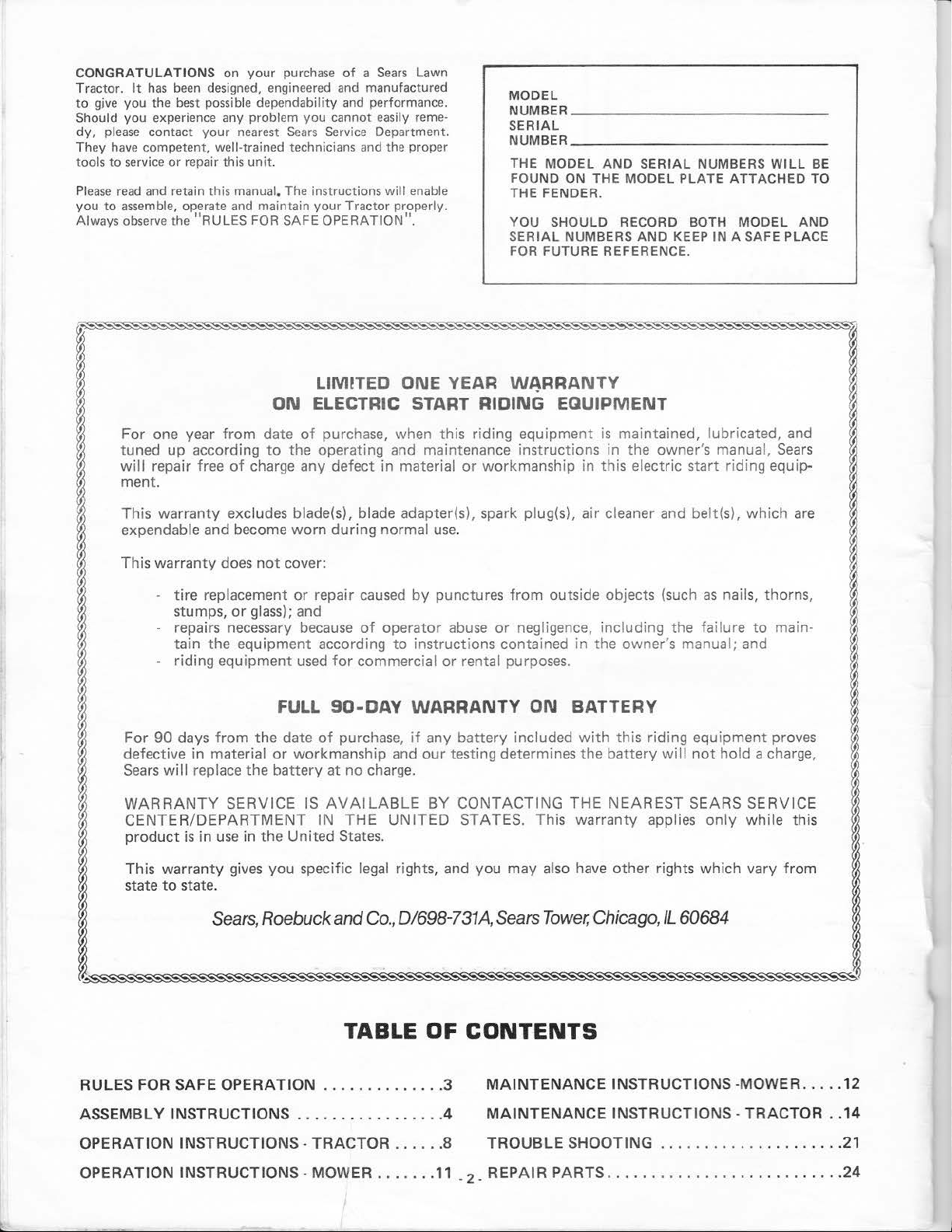
To assemble
two 7
/16" wrenches, two 9/
your
Tractor you will need:
16"
wrenches, two 1/2"
wrenches, a 3/4" wrench and a utility knife
FIGURE
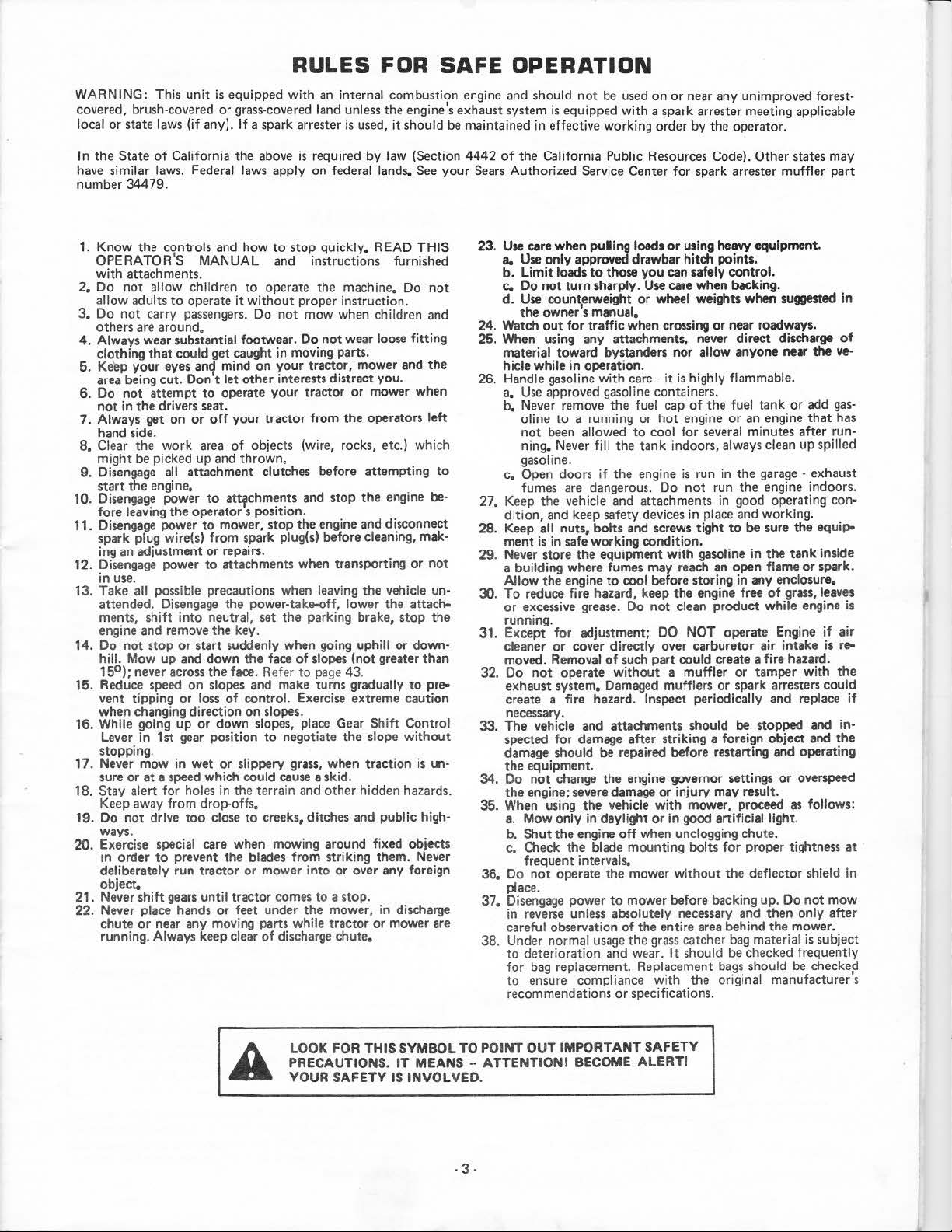
SEAT
FIGURE
1
PAN
2
LOWER
SHAFT
STEERING
FENDER
TUBE
NOTE:
DETERMINED
SEATED
RIGHT
ON
THE
HAND
FROM
TRACTOR.
(R.H.)
AND
LEFT
OPERATOR'S POSITION
HAND
ASSEMBLY
1. Cut
down
carton
at
four
move
Bag
of
Parts.
Slide Upper Steering Shaft over Lower Steering Shaft
2.
bolt
holes line
1).
3.
Use
two
Shaft to Lower Steering Shaft. Tighten securely.
4.
Sl
ide Tube over Stee
Sleeve
Bracket.
5,
Place
Steering Whee
6. With
7,
8.
9. Remove plastic
SEAT
1.
front
Whee
l on
should po
Place
2 · 11
stall a 1 /
Snap Insert
INSTALLATION
Mount
Seat
3/8 - 16 x 3/
two
Crownlock Nuts 3 8 · 16 (Fig. 2).
SHOULD
NUTS. Seat
Bag
of Parts. Tighten Nuts securely.
in
2.
Mount
Seat
Bolts
5/16 • 18 and
of
Bolts
Par
ts. Tighten Nuts securely.
3.
Place Seat on Seat
Lock washer and
Bolt,
Lockwasher and
Tighten finger tight.
4.
Place
Seat in operat ing position.
Clutch-Brake
is
not
comfortable, adjust Seat.
5.
Raise
Seat.
(Fig. 3), When adjusted
Adjustment
up
with
Bolts and
wheels pointed straight ahead, place Steering
Stee
ring
int
straight across tractor.
4"
Dia.
2"
Nut. Tighten
into
Steering
on
Tractor Hood.
Pivot Bracket
4,
two
BE
POS
ITI
P
ivot
Bracket, Bolts,
Pan
to
to
outside). Bolts and Lock Nuts found in
Flat
Pedal
Use
3/
4"
Bolt
securely.
corners,
slots in Lower Steering Shaft (Fig.
two
Locknuts
nng
Shaft Assembly and over Steering
l Adapter on Upper Steering Shaft .
Whee
l Adapter.
Washer
on Upper Steering Shaft and in·
securely.
Whee
to
Washers
ONED
Seat Pivot Bracket using
two Lock
Pan.
Screw Large Adjustment
Washer i
Flat
all the way down.
wrench
for
comfortable operation , tighten
fold
down
to
reta
in
Bars
of
l.
Fender using
13/
32
x 13/16 x 16
UNDER
Nuts 5
nto
Washer found in
to
NOTE:
FENDER
Washers
Seat (Fi
Sit
loosen Adjustment Bo
and Nuts found
/1
6 - 18 (Fig. 2) (head
g.
on the Seat and
If
operating position
Upper Steering
Steering Wheel
two
two
3). Adjustment
Bag
(L.H.)
ARE
WHILE
carton. Re-
unttl
Hex Bolts
Ga.
and
WASHERS
NEXT
TO
Shoulder
Bag
of
Bolt,
of
Parts.
press
lt
BATTERY
a.
-
4-
INSTALLATION
on
Ttacto
READ
WITH
ALWAYS
TECT
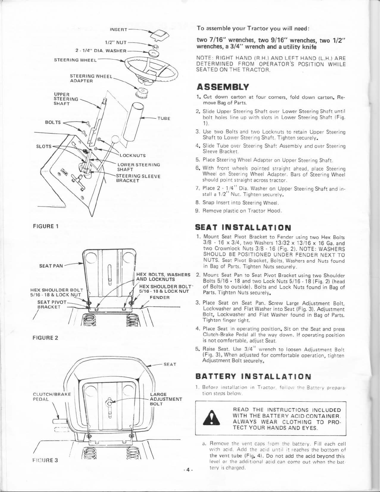
Remove the vent
wtth
actd. Add the
the vent tube (Fig. 4). Do
level
01
tc
the addt ttonal acid
ry
IS
charged.
THE
THE
YOUR
caps
ac•d
INSTRUCTIONS
BATTERY
WEAR
HANDS
ftom
'o
o:
.
;~:
3z::e
y Otepara·
INCLU
ACID
AND
reaches
CONTAINER
TO PRO-
EYES.
the
bottom
out
when the bat
CLOTHING
the battery. Fill each cell
unul
•t
not
add the acid beyond this
can
come
DED
.
of
b. Wait
the level
a,
add more acid
stall
water
c.
Neutralize
to
four
St
ir
ing soda
foaming,
WASH
ATELY
WITH
20
to
of acid falls below the
the vent caps.
to
remove any acid, then wipe
inches
with
until
DO N
ED
HAND
S OR
IF
ACCIDENTALLY
ELECTROLYTE
30
minutes before installing the vent caps.
until
the correct level
Wash
excess
battery acid
of
water in a five gallon plastic container.
a wooden
or
the
OT
ELECTROLYTE
plastic paddle while adding bak-
addition
SMOKE. FUMES
CLOTHING IMM
.
point
as
the
top
of
the
dry.
for
disposal by adding it
of
more
soda
FROM
ARE
EXPLOSIVE.
IN
CONTACT
described
is
reached. In-
battery
causes
CHARG-
no
EDI
in
more
-
step
with
.. :
_.
VENT
CA
P
VENT
TUBE
I·
ATTERY
CELL
FI
GURE
4
CUT
AWAY
VIEW
~
I-========<(
If
c:::::::J c:::::::J
~
::...
.::-~~~·
c::::::J
; :
i-
•:
::
~~~-~~~-~-~B
d. Use a 12
of
the battery is charged.
cor
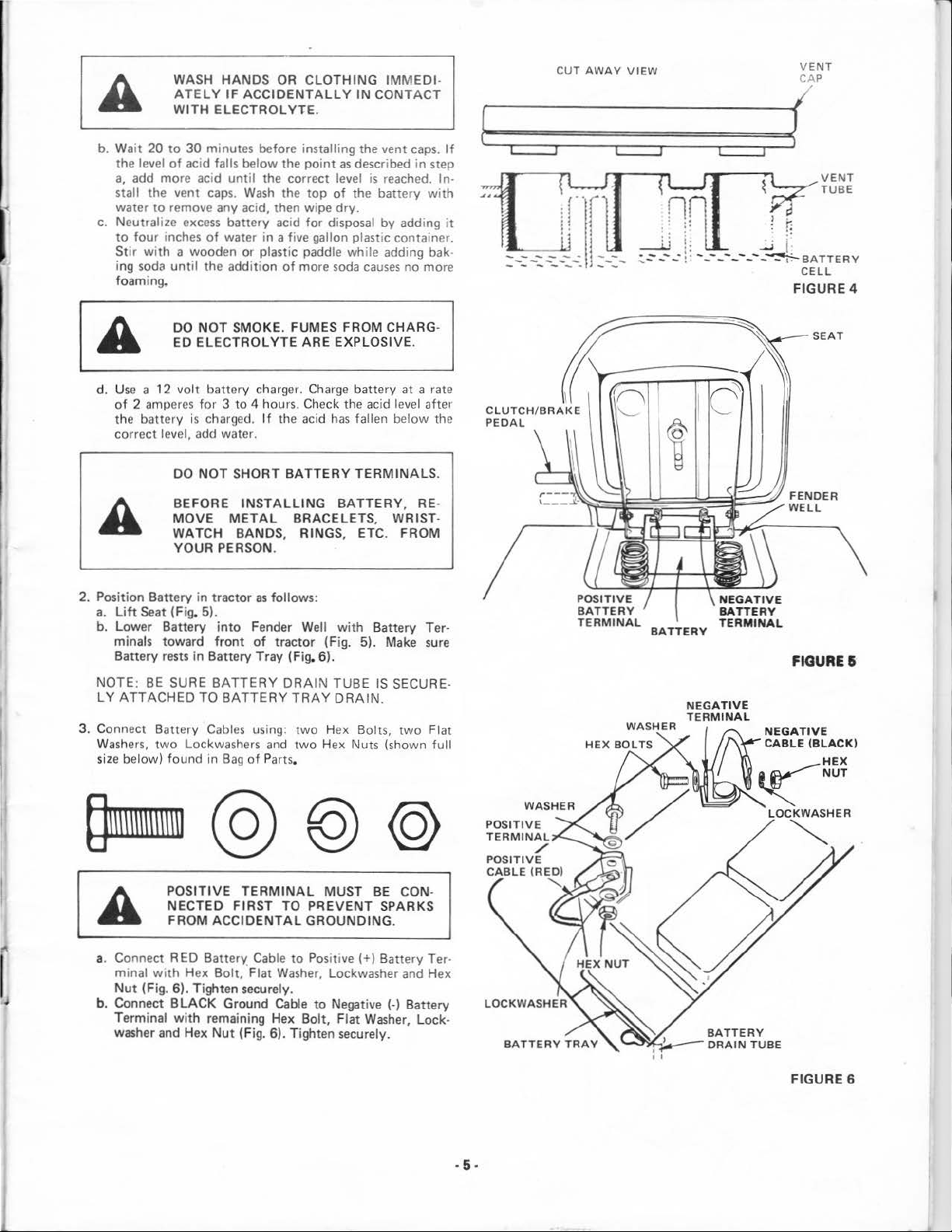
2. Position
a.
Lift
b. Lower Battery
minals
Battery rests
NOTE:
LY
ATTACHED
3. Connect Batter y Cables using: t
Wa
shers,
si
ze
below) found in B
volt
2 amperes
rect level, add water.
Battery
Seat (Fig. 5).
BE
two
battery charge
for 3 to
DO
NOT
SHORT
BEFORE I
MOVE
WATC H
YOUR
to
ward
SURE
POSITIVE
NECTED
FROM
METAL
PERSON.
in
tractor
into
front
in
Battery Tray (Fig. 6).
BATTERY
TO
BATTERY
Lockwashers
ag
FIRST
ACCIDENTAL
BANDS
TERMINAL
4 hours. Chec
If
the acid
BATTERY
NSTALLING
, RINGS
as
follows:
Fender Well
of
tract
DRAIN
and two Hex Nuts (sho
of
Parts.
TO
r.
Charge batte ry
k the acid lev
has
BATTERY
BRACELETS, WRIST
TRAY
, ETC.
with
or
(Fig. 5). Make sure
TUBE
DRAIN
wo
Hex
MUST
P~EVENT
GROUNDING
at
a rate
fallen
TERMINALS
Bolt
el
below
, RE-
FROM
Battery T er·
IS SECURE-
.
s,
two
wn f
BE
CON-
SPA
RKS
.
aft
the
Flat
er
.
-
ull
POSITIVE
TERMINAL
POSITIVE
CABLE
./
(REO)
"
NEGATIVE
TER
MINAL
FIGURE&
NEGATIVE
CABLE (BLACK
)
~~~~
LOCKWASHER
~
a. Connect RED B
minal
with
Nu
t (Fig.
b. Connect
Terminal
washer and Hex Nut (Fig.
attery
Hex
Bolt,
6).
Tighten secure
BLACK
with
remaining Hex
Cable
to
·Flat
Washer,
Ground Cable
ly.
6).
Tighten securely.
Pos
itive(+) Battery
Lockwasher and
to
Negati
Bolt,
Flat
ve
(·) Battery
Wash
er,
Ter
Hex
Lock·
-
BATTERY
.
5.
TRAY
FI
GURE
6
INTERNAL/EXTERNAL
LOCKWASHER
WING
NUT-
INTERNAL/
EXTERNAL~
LOCKWASHER
~
TERMINAL
GUARD
_1/
WING
NUT~
~
(/3!!J
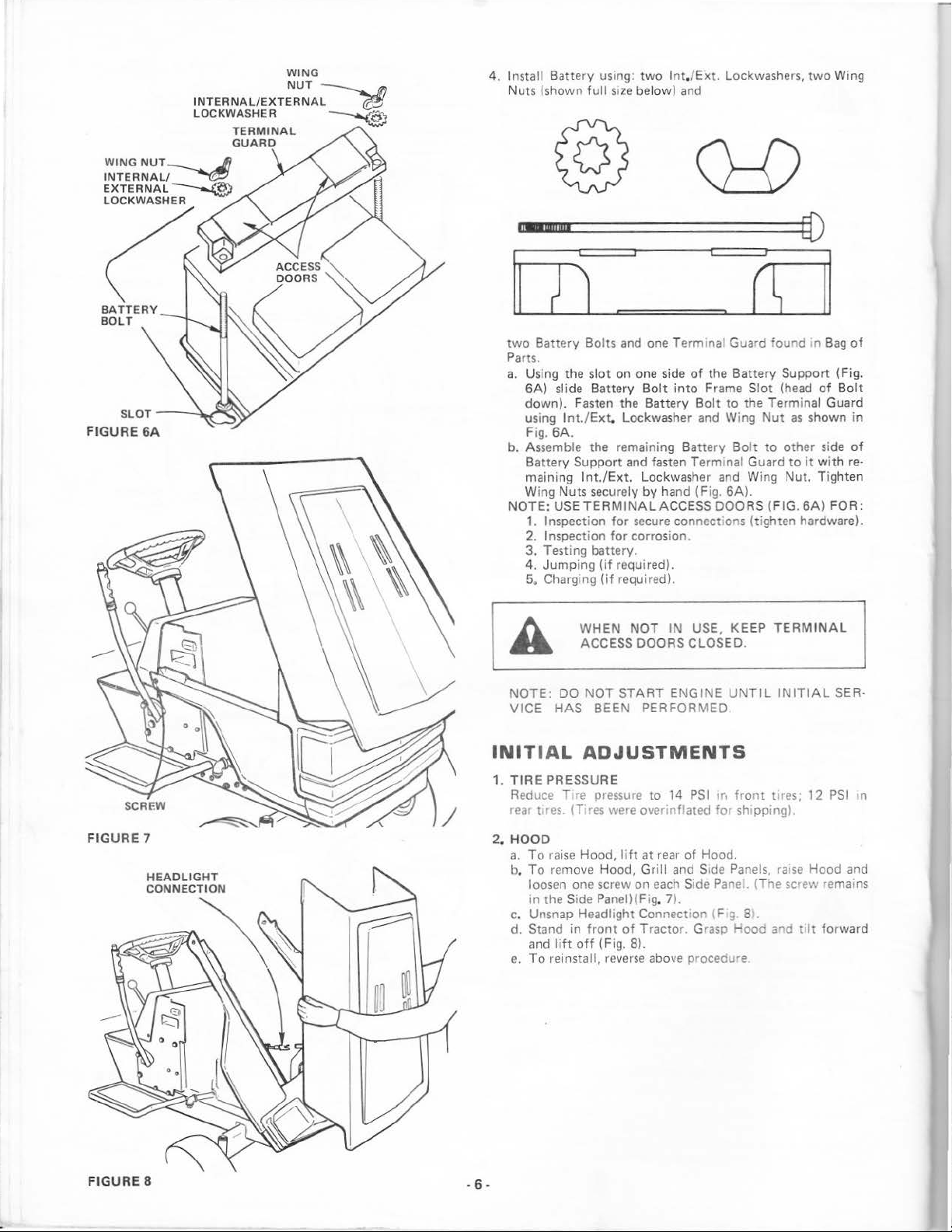
Install Batte
4.
Nuts (shown
ry using:
full
size
two
lnt./Ext.
below) and
Lockwashers,
two
Wing
@
m"IIMIGmmnmm[•::::::::::::::::::::::::::::E[)
SLOT
FIGURE
-
-~_....,~,y
6A
two
Battery Bolts
Parts.
a.
Using the
6A)
slide Battery
down)
. Fasten the Battery
lnt./Ext.
using
Fig.
6A.
b. Assemble the remaining Battery
Battery Support and fasten Terminal Guard
maining
Wing Nuts securely
NOTE: USETER
1. Inspecti
2.
Inspect
and
one Termina Guard 'ound .n
slot
on one side
Bolt
Lockwasher and Wing
lnt./Ext.
on
ion
Lockwash
by
MINALA
for
for
hand (Fig.
secure connect:ons (tighten hardware).
corrosion.
of
into
Frame Slot (head
Bolt
er
CCES
S DOORS (F
3. Testing battery.
4.
Jump
ing
(if
5. Charging
NOTE:
VICE
HAS
INITIAL
1.
TIRE
PRESSURE
Reduce T
res.
rear t
DO
required).
(if
required).
NOT
IN
WHEN
ACCESS DOORS CLOSED.
NOT
START ENGINE UNTIL
BEEN PERFORMED
USE
ADJUSTMENTS
1re
1T1
pressure
res
to
14
were over"nflated
PSI
fs
the Battery Support (Fig.
to
the Terminal Guard
Nut
Bolt
to
and Wing Nut. Tighten
6A).
, KEEP
1ro
for
TERMINAL
front
!Ires;
shipping).
as
shown in
other
to
it with re-
IG.6A)
INITIAL
12
II
Bag
of
side
FOR:
PSI
of
Bolt
of
SER·
n
FIGURE
FIGURE
7
8
.
6.
2.
HOOD
a.
To raise
To
b.
loosen one screw on
in the Side Panei)(Fig. 7
c.
Unsnap Headlight Connection (F g 8
d. Stand in
and
e.
To
Hood,
lift
of
(Fig. 8).
reverse
at rear
eac
Tractor. G
above procedu·e
remove Hood, Grill and Side Panels,
front
lift
off
reinsta
ll,
of
Hood.
h Side Panel. (The screw remains
).
rasp
).
Hooc
ra1se
and
Hood and
tIt
forward
INITIAL SERVICE
NOTE:
THE
FUEL.
1.
2. Check Engine
K
TEWERATURE
CHANGE.
SIFICATION SO, SE,
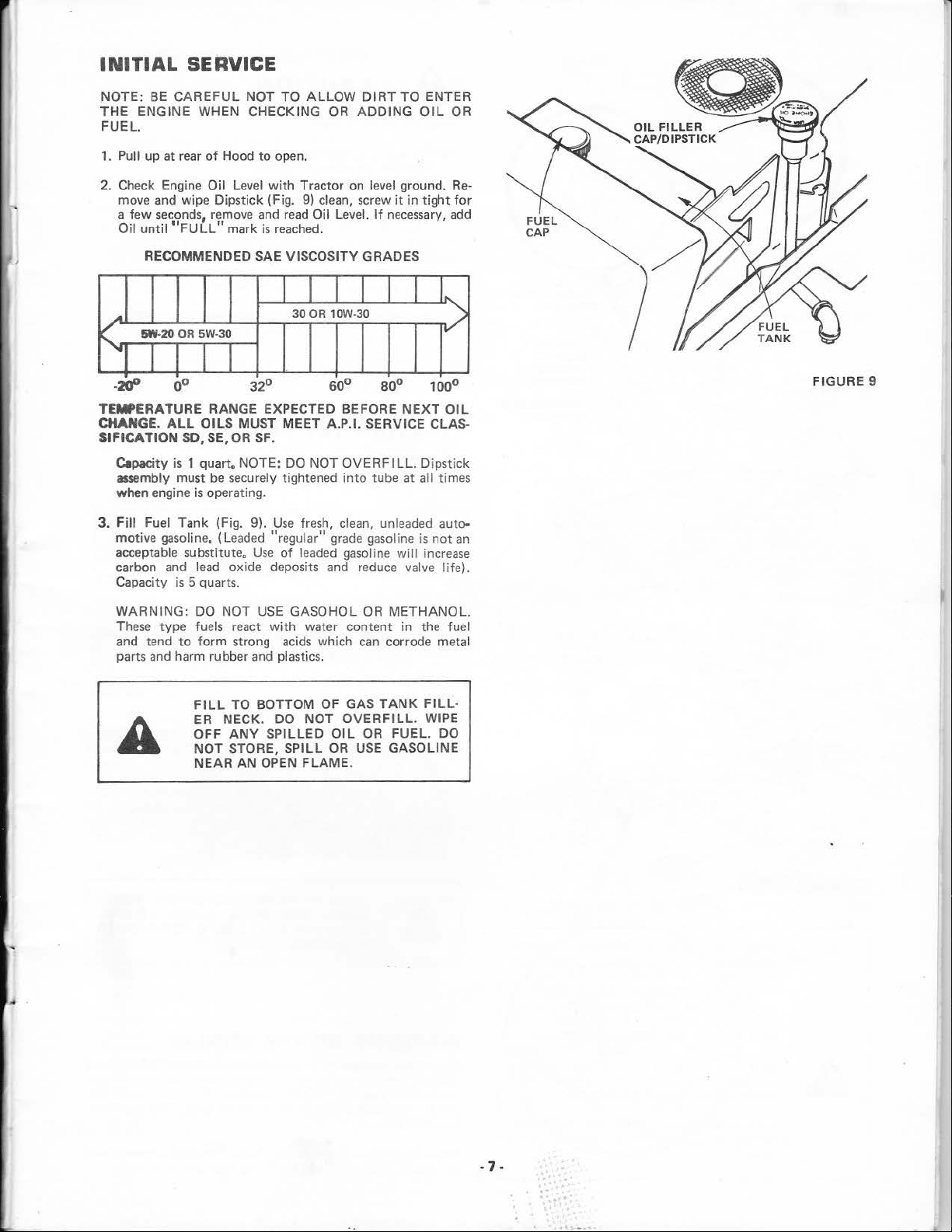
3.
BE
CAREFUL
ENGINE WHEN CHECKING
Pull up at rear
move and wipe Dipstick (Fig.
a
few
seconds, remove and
Oil
untii"FULL"
RECOMMENDED
.A
!iW-20
OR
5W·30
"""
!
-'l.fP
Capacity
assembly must
when engine
Fill
motive gasoline. (Leaded "regular
acceptable substitute.
carbon and
Capacity
0°
ALL
OILS
is
1 quart. NOTE: DO NOT
is
Fuel Tank (Fig. 9).
lead
is
5 quarts.
NOT TO
of
Hood
to
Oil Level
with
mark
is
SAE VISCOSITY GRADES
32°
RANGE EXPECTED BEFORE
MUST MEET A.P.I. SERVICE CLAS-
OR
SF.
be
securely tightened i
operating.
Use
oxide deposits
ALLOW
open.
Tractor on level ground.
9)
read
Oil Level.
reached.
30
OR
Use
fresh, clean, unleaded auto-
of
leaded gasoline
DIRT
OR
ADDING
clean, screw
11
and
If
lOW-30
60°
grade gasoline
80° 1 00°
OVERFILL.
nto
tube at all times
reduce valve life).
TO
it
necessary,
NEXT
will
ENTER
OIL
in
tight
Dipstick
is
not
increase
OR
Refor
add
I~
v
FIGURE 9
OIL
an
WARNING: DO NOT
These
type fuels
to
and tend
parts and harm rubber and plastics.
,.
.
form
FILL
ER NECK. DO
OFF
NOT
NEAR AN
USE
rea
strong acids which can corrode metal
TO
ANY
STORE, SPILL
GASOHOL
ct
with
water content in the fuel
BOTTOM OF GAS
SPILLED
OPEN
FLAME
NOT
OR
OVERFILL
OIL
OR
OR
USE
.
METHANOL.
TANK
FILL-
. WIPE
FUEL. DO
GASOLINE
-7-
. .
...
..
.....
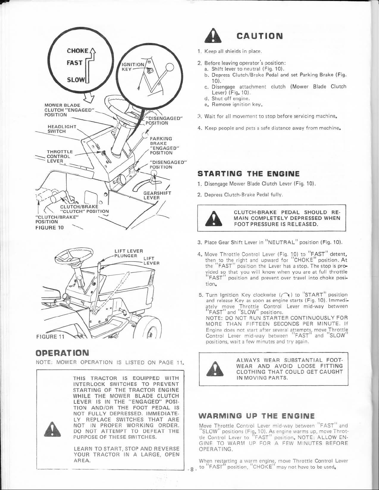
CHOKf
FAST
SLOW
"CLUTCH/BRAKE"
POSITION
FIGURE
10
'-.....__
A
1.
Keep all shields in place.
2.
Before leaving operator's position:
a.
Shift
b. Depress
10)
c.
Disengage attachment clutch (Mower Blade
lever)
d. Shut
e,
Remove ignition key.
::<.
Wait
for all
4. Keep people and pets a safe distance away
STARTING
1.
Disengage Mower Blade Clutch Lever (Fig. 10).
2.
Depre
A
CAUTION
lever
to
neutral (Fi
Clutch/Bra
..
(Fig. 1
off
engine.
movement
ss
Clutch-Brake Pedal
CLUTCH-BRAKE PEDAL
MAIN
FOOT
ke
0).
to
THE
COMPLETELY
PRESSURE IS
g.
10).
Pedal
and set Parking Brake (Fig.
stop before servicing machine.
ENGINE
fully.
DEPRESSED
RELEASED.
from
machine.
SHOULD
Clutch
RE-
WHEN
OPERATION
NOTE:
l ___ _
MOWER
A
OPERATION
THIS
INTERLOCK
STARTING
WHILE
LEVER
TION
NOT
LV
REPLACE SWITCHES
NOT
DO
NOT
PURPOSE
LEARN
YOUR
AREA.
IS
TRACTOR
FULLY
IN
SWITCHES TO
OF
THE
IS
AND/OR
TO
TRACTOR
THE
MOWER
IN
THE
THE
DEPRESSED.
PROPER
ATTEMPT
OF
THESE SWITCHES.
START,
-------------J
LISTED
IS EQUIPPED
TRACTOR
WORKING
STOP
IN A LARGE,
ON
PREVENT
BLADE
"ENGAGED"
FOOT
TO
PEDAL
IMMEDIATE·
THAT
DEFEAT
AND
REVERSE
PAGE 11.
WITH
ENGINE
CLUTCH
POSI-
IS
ARE
ORDER.
THE
OPEN
3. Place Gear
4.
Move
then
the "
vided
"FAST"
tion.
5.
Turn
and
ately move
"FAST"
NOTE
MORE
Engine does
Control
positions, wait a few minutes and
A
WARMING UP
Move
"SLOW"
tie
Control
GINE
OPERATING.
When restarting a warm engine, move
_
to
"FAST"
.
8
Shif
t Lever in
Throttle
to
FAST"
so
Ignition
release
: DO
Throttle
pos
TO
Con
the
that
pos
and " SLOW" positions.
THAN
Lever m1d·way between
iti
lever
WARM
position,
trol
right
and upward for
position the
you
will
ition
and prevent over travel
Key clockwise (
Key
as
soon
Throttle
NOT
RUN
FIFTEEN
not
start
ALWAYS
WEAR
CLOTHING
IN
MOVING
Contr ol
ons (Fig. 10). As eng
to
"FAST"
UP
"CHOKE"
Lever (Fig. 10)
know
Control
STARTER
after
WEAR
AND
THE
lever
FOR A FEW
"NEUTRAL"
Lever has
when
f'l
as
engine starts (Fig. 10).
SECONDS PER
several
AVOID
THAT
PARTS
posi
to
"FAST" detent,
"CHOKE"
a stop. The stop is
you
are
into
)
to
"START"
Lever mid-way between
CONTINUOUSLY
a,~tempt~
FAST
try
aga
in.
SUBSTANTIAL
LOOSE
COULD
.
GET
ENGINE
mid
-way bet\veen
ne
warms up, move
positiOn,
may
NOTE:
MINUTES BEFORE
Throttle
not
have
tion
(Fig. 10).
position.
at
full
throttle
choke posi·
position
lmmed
MINUTE.
move
,Throttl~
1
and SLOW
FOOT-
FITTING
CAUGHT
"FAST"
ALLOW
Control
to
be
used.
At
pro-
FOR
and
Throt
EN-
Lever
i·
If
·
MOWER 'INSTALLATION
Y
our 36" Mower
Lever (F ig. 11) t o its highest position, Turn
ment Knob
In
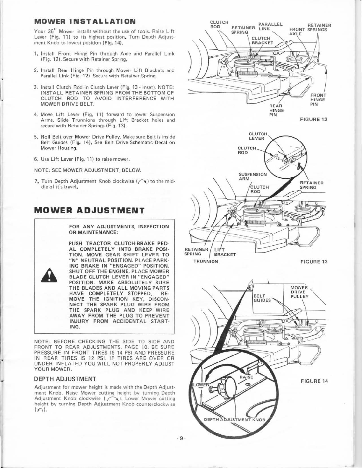
stall Fr
1,
(Fig. 12). Secure
2.
Install Rear Hinge Pin through Mower Li
Parallel
3.
Insta
INSTALL
CLUTCH ROD TO
MOWER
4.
Move Lift Leve
Ar
se
5.
Roll Belt over Mower Dri
Belt
Mower Housing.
6.
Use Lift
NOTE:
7,
link
ll
Clutch Rod in Clutch Lever (Fig. 13 -
ms. Sli
cure
with
Guides (Fig, 14).
SEE
Turn
Depth
dle
of
it's
installs
witho
ut the
use
of
to
lowest pos
ont
(Fig. 12).
RETAINER
DRIVE
de Trunnions through
Retainer Spri
Lever
MOWER
Adjustment
travel,
iti
on (Fig. 14).
Hinge Pin through
with
Retainer Spring,
Secu
SPRING FROM
AVOID
BELT.
r (F ig. 11) forward to lower Suspension
ngs
ve
See
(Fig.11)
to
rai
ADJUSTMENT,
Knob clockwise ((-"'\)
Axle
and Parallel
re
with
Retainer Spring.
THE
INTERFERENCE WI
Lift Bra
(Fig. 13).
Pulley. Make sure Belt
Belt Drive Schematic Decal on
se
mower.
BELOW.
tools. Rai
ft
cket holes and
se
NOTE:
is ins
to
the mid-
Lift
djust
Lin
TH
Depth A
Brackets and
Inset).
BOTTOM OF
ide
CLUTCH
ROD
-
k
FRONT
HINGE
PIN
FIGURE
12
CL
ROD
CLUTCH
LEVER
UTCH
REAR
HINGE
PIN
MOWER
NOTE: BEFORE CHECKING
FRONT
PRESSURE
IN
UNDER
YOUR
TO
REAR
INFLATED
MOWER.
ADJUSTMENT
FOR
ANY
MAINTENANCE
OR
PUSH
AL
TION. MOVE
"N"
ING
SHUT
BLADE
POSITION.
THE
HAVE
MOVE
NECT
THE SPARK PLUG
AWAY
INJURY
ING
.
REAR
IN
FRONT TIRES
TIR
ES
ADJUSTMENTS, INSPECTION
TRACTOR
COMPLETELY
NEUTRAL
BRAKE
BLADES
ADJUSTMENTS, PAGE 10,
IS
IN
OFF
THE ENGINE. PLACE MOWER
CLUTCH
MAKE
AND
COMPLETELY
THE
THE SPARK PLUG WIRE FROM
YOU
IGNITION
FROM THE PLUG TO
FROM ACCIDENTAL
12 PSI.
WILL
:
CLUTCH-BRAKE
GEAR
POSITION. PLACE
" ENGAG
LEVER IN
ABSOLUTELY
ALL
THE SIDE TO SIDE
IS 14
IF
TIRES
NOT PROPERLY
DEPTH ADJUSTMENT
Adjustment
ment
Adjustment Knob clockwise (
he
i
ght
for
Knob. Rai
by turning Depth Adjustment Knob countercl
mower heig
se
Mower
ht
is
cutting
~
made
hei
(F'\l.
INTO
BRAKE
SHIFT
AND KEE
with
ght
). Lower Mower
LEVER
ED"
POSITION.
"ENGAGE
MOVING
STOPPED, R
KEY,
PSI
by
PARTS
DISCON·
P WIRE
PREVENT
START-
BE
AND
PRESSURE
ARE
OVER
the Depth Adjust-
turn
ing
PED-
POSI-
TO
PARK
-
D"
SURE
E-
AND
SURE
OR
ADJUST
Depth
cutting
ockwise
FIGURE 13
FI
GURE
14
- 9 -
LIFT
LEVER
PLUNGER
LIFT
LEVER
TOP
FLANGE
FIGURE 15
SIDE-
TO-SIDE
ADJUSTMENT
TRUNNION
FIGURE
16
OF
A
-_J_.llio<...._.,.
SIDE-TO-SIDE
ADJUSTMENT
A
I
NUT"B"
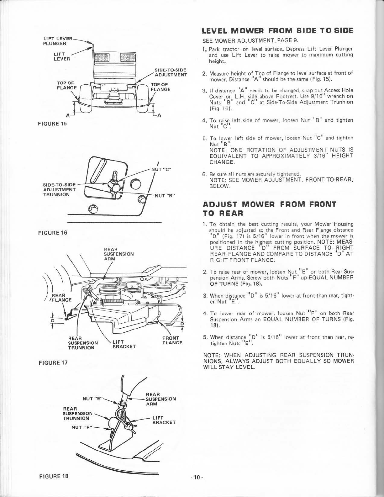
LEVEL
SEE MOWER ADJUSTMENT, PAGE
1.
Park tractor on
and
height.
2.
Measure
mower. Distance
3.
If
Cover on L.H.
Nuts
(Fig.
4.
To
Nut"c"
5.
To
Nut
NOTE:
EQUIVALENT
CHANGE.
6.
Be
NOTE: SEE MOWER ADJUST MENT, FRONT-TO BELOW.
ADJUST
TO
1.
To
should
"D" (Fig
positioned in the
URE DISTANCE 1 D" FROM SURFACE TO
REAR
RIG
MOWER FROM
use
height
distance
"B"
16).
raise l
lower l
"B".
ONE
sure all
Lift
eft
level
Lever
of
Top
"A"
"A"
needs
si
de
and
"c"
s1de of
eft
side
ROTATION OF ADJUSTM
TO APPROXIMATELY 3/
nuts
are
securely
MOWER FROM FRONT
REAR
obtain the best
be adjusted
. 17) is 5
FLANGE AND
HT
FRONT
/1
t>i~hest
FLANGE.
SIDE
9.
surface.
to
of
should
to
above
at Side-To-Side Adjustment
mower, l
of
mower, loosen
cutting
so
the Front and
6" lower in
COMPARE TO DISTANCE
Depress
raise
mower to maximum
Flange
be
the
be
chan
Footrest-
oosen
tightened.
results,
cutt
ing position. NOTE: MEAS-
Lift
to
level surface
same
(Fi
ged, snap
front
out
Use
9/
Nut
"s" and tighten
Nut
"c "
your Mower Housing
Rea
r Fl
when the mower
TO SIDE
Lever Plunger
cutting
at
front
g.
15).
Access
16"
wrench
Trunnion
and
t ighten
ENT
NUTS IS
16"
HEIGHT
REAR,
ange
distance
RIGHT
"D"
of
Hole
on
is
AT
FIGURE
REAR
SUSPENSION
TRUNNION
17
REAR
SUSPENSION
TRUNNION
NUT
"F"
-~
·"--"
2.
To
rai
se rear of
pens
ion Arms. Scre
OF
TURNS
3. When distance "D"
en
Nut
"E".
4.
To
lower rear
Suspens
ion A
mower, loos
w both Nuts '
(Fig. 18).
of
mower, l
rms
an
is
5/16
EQUAL
en
Nut
'F"
" lower at
oosen
Nut
NUMBER OF
''E"
on both Rear
up
EQUAL
front
"F"
than rear, tight-
on
TURNS (Fi
18).
5.
Whe
n distance "D"
tighten Nuts
NOTE: WHEN ADJUSTING REAR SUSPENSION
NIONS,
WILL
STAY
"E".
ALWAYS
LEVEL.
is
5/
16"
lower at
ADJUST BOTH EQ
front
than rear, re-
UALLY SO
Sus·
NUMBER
both
Rear
TRUN-
MOWER
g.
FIGURE
18
-10-
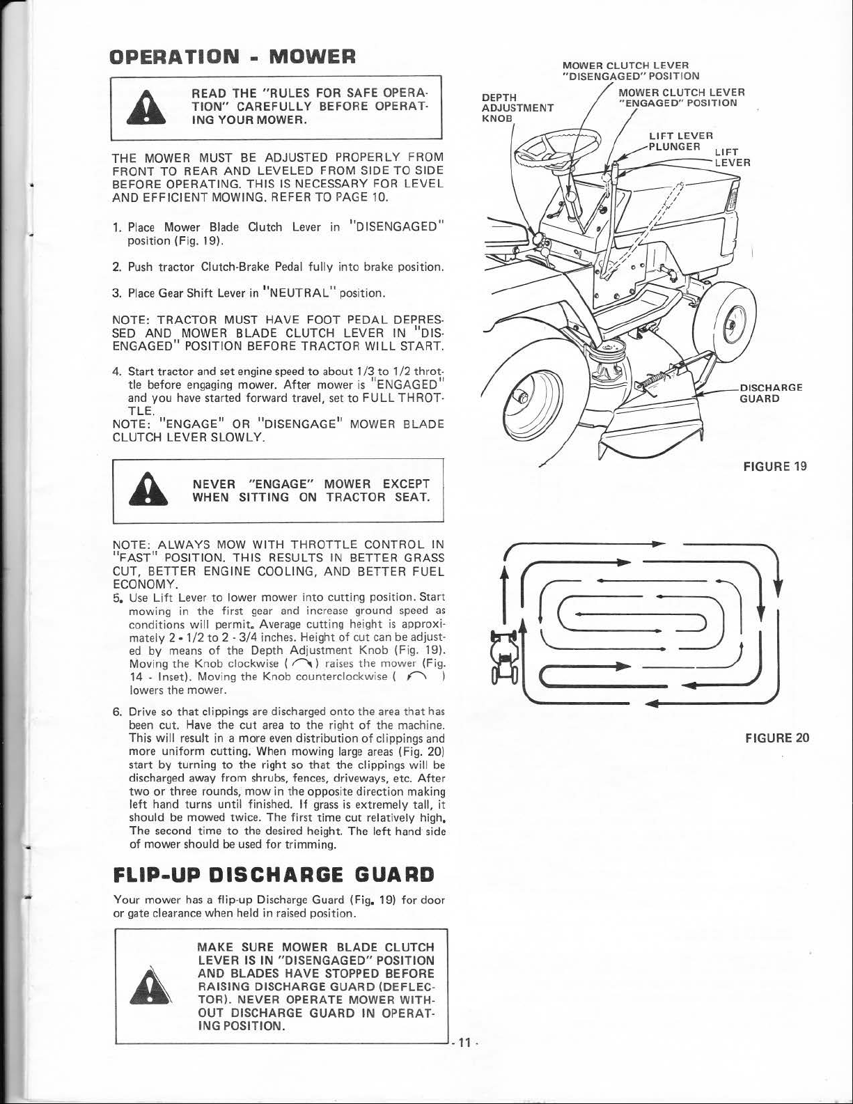
OPERATION
READ THE
TION"
ING
YOUR MOWER.
-
MOWER
"RULES
CAREFULLY
FOR SAFE OPERA-
BEFORE OPERAT-
DEPTH
ADJUSTMENT
KNOB
MOWER
"DISENGAGED"
CLUTCH
MOWER
"ENGAGED"
LEVER
POSITION
CLUTCH
POSITION
LEVER
THE MOWER MUST
FRONT TO
BEFORE OPERATING. THIS IS NECESSARY
AND
1.
Place
position (Fig. 19).
2.
Push
Place
3.
NOTE: TRACTOR MUST HAVE FOOT PEDAL DEPRES-
SED
ENGAGED" POSITION BEFORE TRACTOR
4. Start tractor and set engine
tle before
and
TLE
NOTE:
CLUTCH LEVER SLOWLY .
NOTE:
"FAST"
CUT,
ECONOMY.
5.
Use Lift
mowing in t
conditions w
mately 2 • 1/2 to 2-3/4
ed
Moving the Knob clockwise (
14
lowers the mower.
6. Drive
been
This
more uniform cutting.
start by turning
discharged away
two
left
should
The second time
of
REAR
EFFICIENT MOWING. REFER
Mower Blade Clutch Lever
tractor Clutch-Brake
Gear
Shift
AND
MOWER
engaging
you
have
.
"ENGAGE"
NEVER "
WHEN
ALWAYS
POSITION. THIS RESULTS IN BETTER GRASS
BETTER ENGINE COOLING, AND BETTER
Lever
by
means
- Inset). Moving the Knob counterclockwise ( 0 )
so
that
cut.
Have
will
result in a more
or
three rounds, mow in the opposite direction making
hand turns
be
mowed twice. The
mower should be
BE
ADJUSTED PROPERLY FROM
AND
LEVELED FROM SIDE TO SIDE
TO
Pedal
fully into
Lever in '
started forward travel,
MOW
to
he first
ill
permit.
of
clippings
the
to
from
until
'NEUTRAL"
BLADE
mower.
OR
SITTING
lower mower into cutting position. Start
the Depth Adjustment Knob (Fig. 19).
cut
the right
to
used
CLUTCH LEVER IN 11DIS-
speed
to
about 1/3
After
mower
set
"DISENGAGE"
ENGAGE"
WITH
gear
and
Average
inches. Height
are
discharged
area
even
When
shrubs, fences, driveways, etc.
finished.
the desired height. The
for
MOWER EXCEPT
ON
TRACTOR SEAT.
THROTTLE
increase
cutting height
~)
raises
onto
to
the right
distribution
mowing large
so
that
If
grass
first
time cut relatively high.
trimming.
FOR
PAGE
10.
in
''DISENGAGED"
brake position.
position.
WILL
to
is
"ENGAGED"
to
FULL
MOWER BLADE
CONTROL IN
ground
of
cut
can
the mower (Fig.
the
area
of
the machine.
of
clippings
areas
the clippings
is
extremely tall,
left
LEVEL
START.
1/2 throt-
THROT
FUEL
speed
is
approxi-
be
adjust-
that
(Fig. 20)
will
Aft
hand side
has
and
as
be
er
-
FI
GURE 19
FIGURE
it
20
FLIP-UP
Your mower
or
gate clearance when held in
~--------------------------------------~
DISCHARGE
has
a flip-up Discharge Guard (Fig. 19)
MAKE
LEVER IS
AND
BLADES
RAISING DISCHARGE
TOR). NEVER OPERATE MOWER WITHOUT DISCHARGE
ING
POSITION.
raised
SURE MOWER BLADE CLUTCH
IN
"DISENGAGED"
HAVE
GUARD
position.
STOPPED BEFORE
GUARD (DEFLEC-
GUARD
POSITION
IN
OPERAT-
for
door
-11-
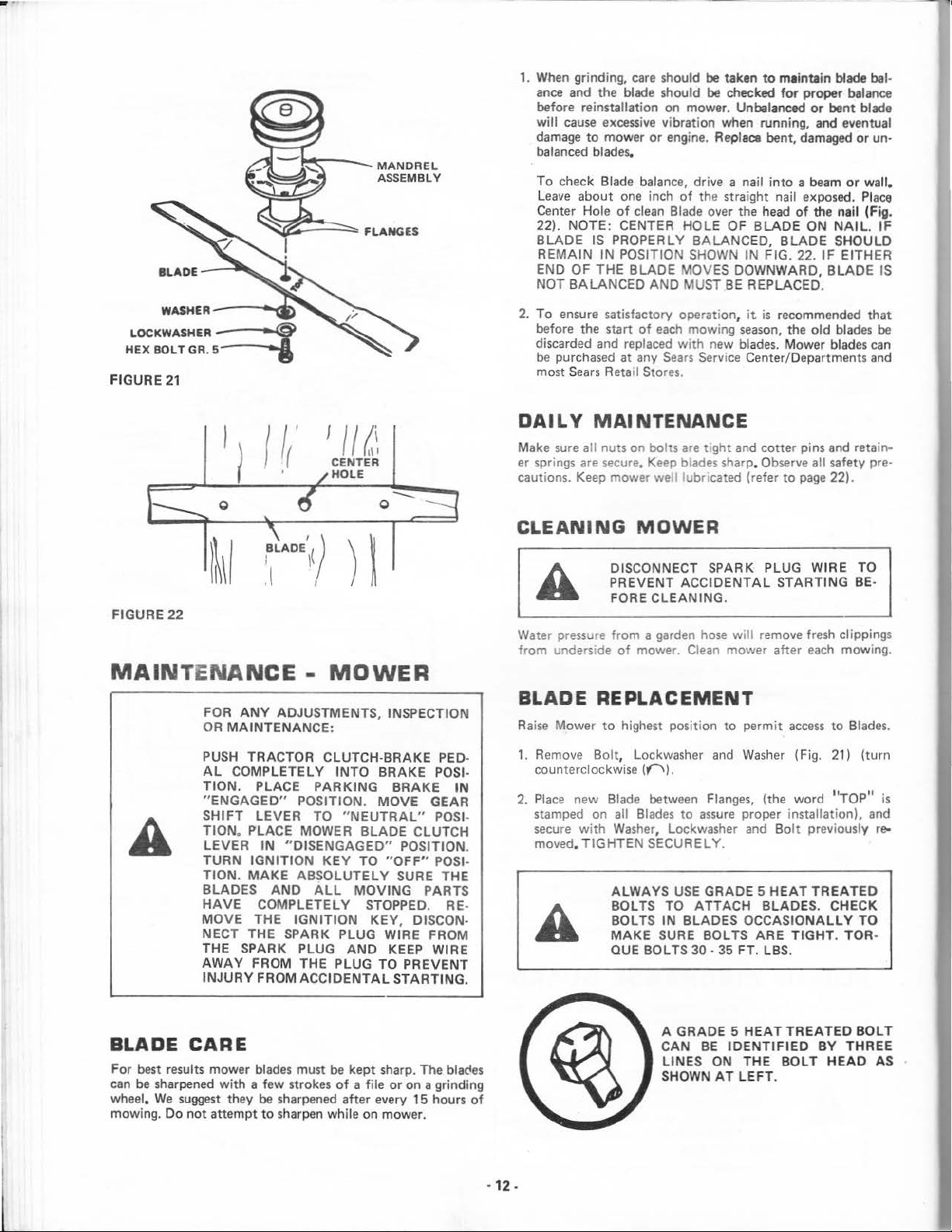
LOCKWASHER
HEX
BOL
FIGURE
WASHER----~:o.
~
T GR.
5---.....
21
'
II~~.
CENTER
HOLE
0
---
1.
When grinding, care should
ance
and the blade should
before reinstallation on mower. Unbalanced
will
cause
damage
balanced blades.
To
leave about one inch
Center Hole
22).
BLADE
REMAIN
END
NOT
2.
To
before the start
discarded and replaced
be
purchased at any
most
excessive
to
mower
or
check Blade balanc
of
NOTE: CENTER HOLE OF
OF
BALANCED
ensure satisfactory operation,
Sea
clean
IS PROPERLY BALANCED,
IN
POSITION SHOWN IN FIG. 22.
THE
BLADE MOVES DOWNWARD, BL
AND
of
each
rs
Reta
il
Stor
be
taken to maintain blade bal·
be
checked
vibration when running, and eventual
engine. Replace bent, damaged
e,
drive a nail
of
the straight nail exposed. Place
Blade over the head
MUST
mowing
with
Sears
Service Center/Departments and
es.
BLA
BE
REPLACED.
it
season,
new blades. Mower blades
DAILY MAl NTENANCE
Make sure a
er sprin
cautions. Keep mower
ll
gs
are secure.
nuts on bolts
Keep
welllubr
are
tight and cotter pins and retain·
blades sharp. Observe all safety pre·
cated (refer
CLEANING MOWER
for
proper balance
or
into a beam
of
the nail (Fig.
DE ON
BLADE
is
recommended
the
old
to
page
bent blade
or
or
wall.
NAIL.
SHOULD
IF
EITHER
ADE
that
blades
22).
un-
IF
IS
be
can
FIGURE
22
MAINTENAN
FOR
ANY
MAINTENANCE:
OR
PUSH
TRACTOR CLUTCH-BRAKE PED·
AL
COMPLETELY INTO BRAKE POSI·
TION.
"ENGAGED"
SHIFT LEVER
TION
. PLACE MOWER BLADE CLUTCH
LEVER
TURN IGNITION
TION.
MAKE
BLADES
HAVE
MOVE
THE SPARK PLUG WIRE FROM
NECT
THE SPARK PLUG
AWAY
INJURY
CE
- MOWER
ADJUSTMENTS, INSPECTI
PLACE
IN
COMPLETELY STOPPED. RE·
THE
FROM THE PLUG TO PREVENT
FROM
PARKING
POSITION. MOVE GEAR
TO
"NEUTRAL"
"DISENGAGED"
KEY
ABSOLUTELY
AND
ALL
IGNITION
AND
ACCIDENTAL
BRAKE
POSITION.
TO
"OFF"
SURE THE
MOVING
KEY, DISCON·
KEEP WIRE
STARTING.
ON
IN
POS
POSI-
PARTS
Water
fr
om
pressure
underside
DISCONNECT SPARK PLUG W
PR
EVENT
FORE
from a garden
of
ACCIDENTAL
CLEANING.
mower. C
hose
will
lean
mower after
STARTING
remove fresh clippings
IRE
each
TO
BE·
mowing.
BLADE REPLACEMENT
Raise
Mower
1.
Remove Bolt, lockwasher
counterclockw
2.
Place
I·
stamped on all Blad
secure
moved.
to
highest position
ise (("\).
new Blade between
with
Was
TIGHTEN
her, lockwasher
SECURELY.
ALWAYS
BOLTS TO
BOLTS IN BLADES
MAKE
QUE BOLTS 30 · 35 FT. LBS.
SURE BOLTS ARE
es
USE
Flanges,
to
assure
GRADE 5
ATTACH
to
permit
access
and
Washer
proper installation). and
and
OCCASIONALLY
(Fig. 21) (turn
(the word
Bolt
previously
HEAT
BLADES. CHECK
TREATED
TIGHT
to
Blades.
''TOP"
TO
. TOR·
is
re-
BLADE CARE
For best results mower blades must
can
be
wheel.
mowing.
sharpened
We
Do
suggest
not
attempt
with
a few strokes
they
be
sharpened after every 15 hours
to
sharpen while on mower.
be
of
kept
a file
sharp. The
or
on
a grinding
blacles
of
.
12.
A GRADE 5
CAN
BE
LIN
SHOWN
IDENTI
ES ON THE
AT
HEAT
LEFT.
TREATEDBO
FIED
BY
BOLT
HEAD
LT
THREE
AS
,__
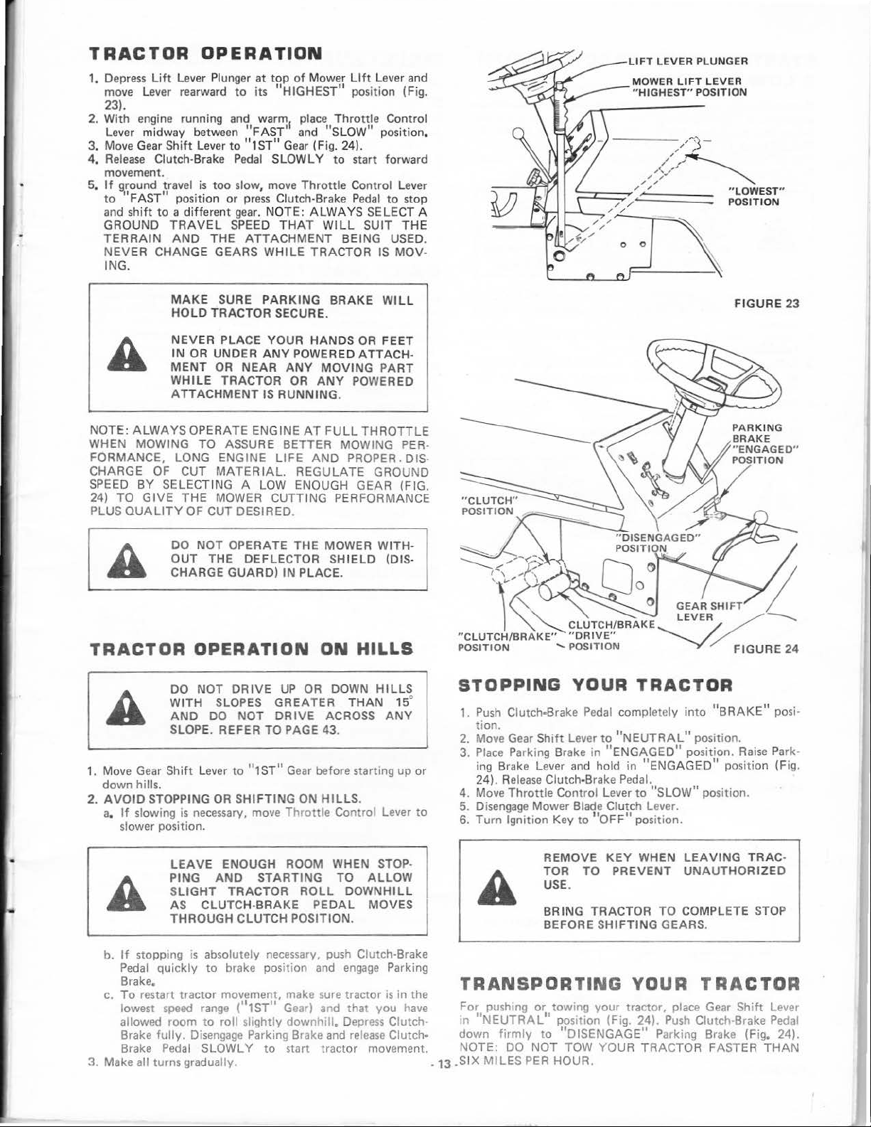
TRACTOR
1.
Depress
move
23).
2. With engine running and
Lever midway between "FAST'
3. Move
4.
Release
movement.
5.
If
to
and
GROUND
TERRAIN
NEVER CHANGE
ING.
lift
Leve
Gear
Clutch-Brake
9,round travel
'FAST"
shift
to
OPERATION
Lever Plunger
r rearward
Shift
position
a different
TRAVEL
AND
Lever
is
too
THE
GEARS
to
to
Pedal
slow, move
or
gear
SPEED
at
top
of
its
warm1 place
"1ST" Gear (Fig
press Clutch-Brake
. NOTE:
ATTACHMENT
WHILE
Mower
"HIGHEST
Throttle
and "SLOW" position.
SLOWLY
THAT
. 24).
to
Thrott
le Control Lever
ALWAYS
WILL
TRACTOR IS MOV-
Lift
Lever and
11
position (Fig.
Control
start forward
Pedal
to
stop
SELECT A
SUIT THE
BEING USED.
LIFT
LEVER
MOWER
" HIGHEST"
PLUNGER
LIFT
POSITION
LEVER
MAKE
HOLD
NEV
IN OR UND ER
MENT
W
ATTACHMENT
PLUS
ALWAYS
BY
TO
GIVE
QUALITY
SELECTING A LOW ENOUGH GEAR (FIG.
DO
OUT
CHA
NOTE:
WHEN MOWING
FORMANCE, LONG ENG INE
CHARGE OF CUT
SPEED
24)
SURE
TRACTOR SECURE.
ER
OR
HILE
OPERATE ENGINE
TO
MATERIAL.
THE
MOWER CUTTING PERFORMANCE
OF CUT DESIRED.
NOT
THE DEFLECTOR
RGE
PARKING
PLACE YOUR HANDS
ANY
NEAR
TRACTOR OR
ASSURE BETTER MOWING PER-
OPERATE THE MOWER WITHGUARD)
ANY
IS RUNNING.
LIFE
IN PLACE.
BRAKE
POWERED ATTACH-
MOVING
ANY
AT
FULL
AND
REGULATE GROUND
PROPER. DIS-
SHIELD
WIL
OR
FEET
PART
POWERED
THROTTLE
(DIS-
TRACTOR OPERATION ON HILLS
1.
Move Gear
down hills.
2.
AVOID
a.
If
slower position.
DO NOT
WITH SLOPES GREATER
AND
SLOPE. REFER
Shift
STOPPING
slowing
is necessary,
Lev
DO
er
OR
DRIVE
to
UP
OR DOWN
NOT
DRIVE
TO
PAGE 43.
"1ST " Gear
SHIFTING ON
move
Throttle Control Lever
HILLS
THAN
ACROSS
before starting up
HILLS.
15°
ANY
L
STOPPING
1.
2.
3.
or
4.
to
5.
6.
Push
Clutch·Brake
tion.
Move
Gear
Place Parking Brake in
i
ng
Brake Lever
24).
Release
Move
Throttle
Disengage
Turn
Ignition Key to 1'0FF"
YOUR TRACTOR
Pedal
complete
Shift
Lever to 1'NEUTRAL"
"ENGAGED"
and
hold in
Clutch-Brake Pedal.
Control Lever
Mower Blade Clutch Lever.
ly
"ENGAGED"
to
"SLOW"
pos
ition.
into
position.
"BRAKE"
position.
position (Fig.
pos
ition.
FIGURE
posi-
Raise Park-
23
LEAVE
PING
SLIGHT
AS CLUTCHTHROUGH CLUTCH POSITION.
b.
If
stopping
Pedal
quickly
Brake.
c.
To
restart tractor movement, make sure tractor
lowest
speed
allowed room to roll slightly
Brake
fully.
Brake
3. Make all turns gradually
Pedal
ENOUGH ROOM WHEN STOP-
AND
is
absolutely
to
range
Disengage
SLOWLY
STARTING
TRACTOR
BRAKE
brake position
t1ST"
Parking Brake
ROLL
necessary,
Gear)
downhill.
to
start tractor movement. NOTE: DO
TO
ALLOW
DOWNHILL
PEDA L MOVES
push
Clutch-Brake
and
engage
and
Depress
and
Parking
is
that
release
in
you
ClutchClutch· down
have
the
REMOVE
TOR TO
USE
BRING
BEFORE SHIFTING GEARS.
TRANSPORTING
For
1n
-13 .SIX
pushing
"NEUTRAL
MILES
or
towing
1
'
firmly
position (Fig. 24).
to 11DISENGAGE"
NOT
PER HOUR.
KEY
WHEN
.
PREVENT
TRAC
TOR
YOUR
your
tractor, place Gear
TOW YOUR TRACTOR FASTER
LEAVING
UNAUTHORIZ
TO
COMPLETE STOP
TRAC-
TRACTOR
Push
Parking Brake (Fig. 24).
Shift
Clutch-Brake
ED
Lever
Pedal
THAN
STARTING
A
LOW
If
your
recharged.
follow
PED
THE
TIVE
1. Connect each end
2. Connect one end
3. Connect the
4.
Battery is
If
this procedure.
WITH
A 12
OTHER
GROUNDED
terminals
chassis).
H terminal
or
good CHASSIS
Tank
or
Battery).
Disconnect cables in reverse order·
a.
Engine
b. Negative terminal
c.
Positive terminals.
YOUR
BATTERY
too
"Jumper
VEHICLE
LEAD
PLOSIVE GASES.
AND
FROM
PROTECTION
of
each
of
Block
low
Cables" are
NOTE:
VOLT
SYSTEM.
-ACID
SMOKING
BATTERIES.
of
battery
of
the
fully
charged battery.
other
end
GROUND
or
chassis
of
NEGATIVE
MUST
the RED Cable
of
fully
to
BATTERIES
BLACK
TRACTOR
start the engine,
used
YOUR
ALSO
AROUND
(taking care
the cable
of
charged
for
TRACTOR
GROUNDED
BE A 12
KEEP SPARKS,
MATERIALS
ALWAYS
BATTERIES.
to
Cable
to
on
tractor
tractor.
battery.
WITH
it
emerge11cy
should be
,s
SYSTEM
VOLT
GENERATE
not
to
FLAME
AWAY
WEAR
the POSITIVE
to
short against
the
NEGATIVE
ENGINE
(away
from
starti
ng
EQUIP-
NEGA
EX-
,
EYE
(+-)
BLOCK
Gas
MAINTENANCE-
\/lOWER
-o
sary service using the
DAILY
Make sure all nuts on bolts
er spn
tor
FIRST~
1.
NOTE:
THE
MAINTENANCE
keep
your
tractor
REFER TO "STOPP
TOR"
SPARK
CIDENTAL
ANY
REPAIR
MAINTENANCE
ngs
are secure. Observe al safety precautions. Keep trac-
well lubricated (refer
HOURS
CHANGE
Changing
break-in
ENGINE
Oil
aher
res1due
BE
EI\IGII\IE WHEN
wh1ch m•ght
CAREFUL
IS LISTED
running better, onger,
following
PAGE 13
PLUG WIRE TO
STARTING
INSPECTION,
(EXCEPT
are:
to
page
OIL
the f1rst
NOT
TO
CHANGING
TRACTOR
ON
PAGE 12.
Maintenance Schedule.
ING
AND
ADJUSTMENT
CARBURETOR).
gnt and
22).
two
hours
be
damaging
ALLOW
OIL.
perform
YOUR
DISCONNECT
PREVENT AC·
BEFORE
cotter
MAKING
pins and retain·
will
help eliminate
to
your
DIRT
TO
neces·
TRAC-
OR
Engine.
ENTER
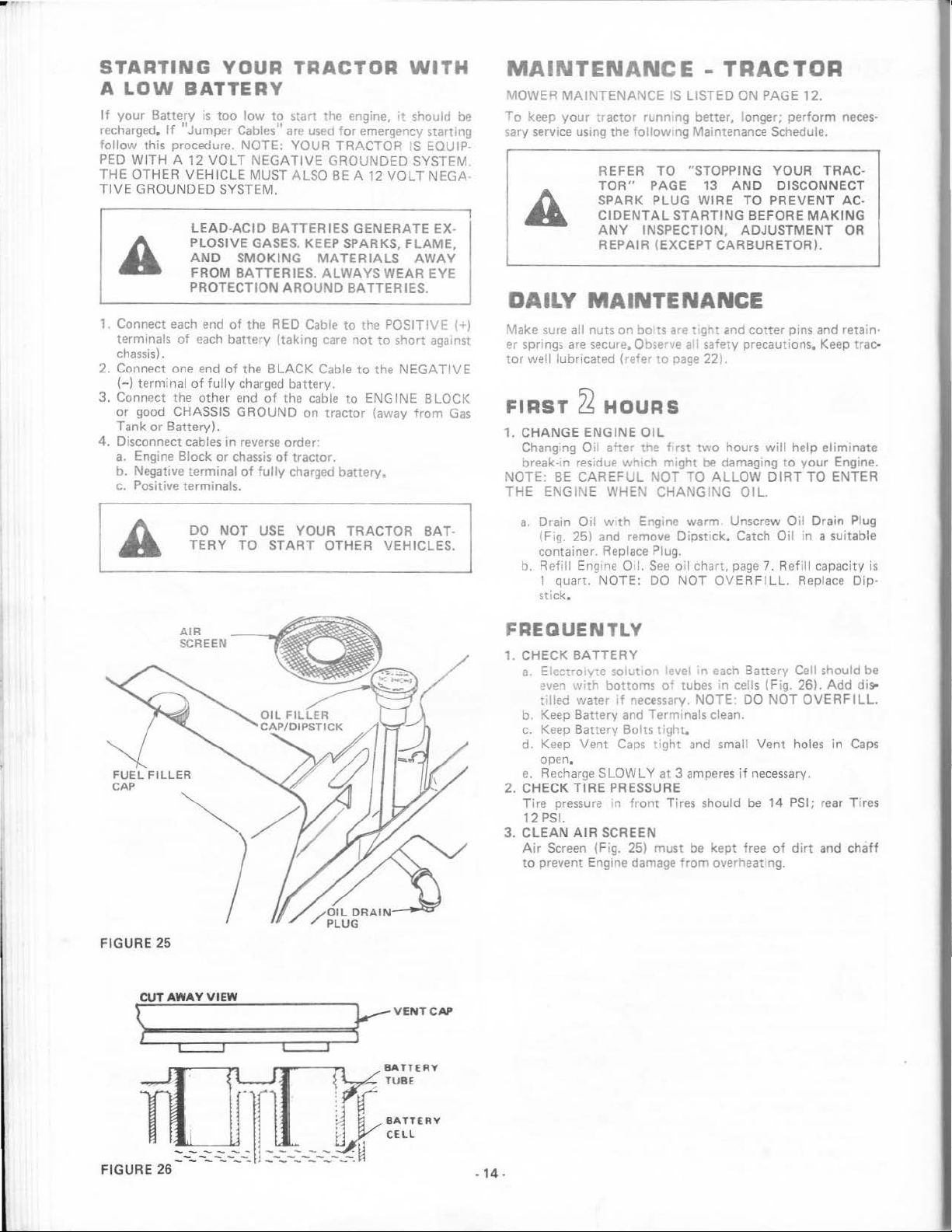
FIGURE
25
DO
TERY
AIR
SCREEN
NOT
TO
USE
START
YOUR
OTHER
TRACTOR
VEHICLES.
BAT·
a Drain
b. Refill Eng
Oil
w•th
me
Oil.
NOTE:
Engme
See
DO
(F1g.
25) and remove
container. Replace Plug.
1 quart.
stick,
warm
Dipstick.
oil
chart,
NOT
fREQUENTLY
1.
CHECK
a E ectro
b Keep Battery and Termmals clean.
c.
d. Keep Vent
e.
2. CHECK
Tire
12 PSI.
3.
CLEAN
Air
to
BATTERY
v:e
so
ut
with
even
t
1.ed
water
Keep
Battery
open.
Recharge
TIRE
pressur<? m front
AIR SCREEN
Screen {Fig. 25) must
prevent Engine damage
o 1 level ·n !!ach
bottoms
SLOWLY
PRESSURE
of
if
necessary. NOTE. DO
Bolts
tight.
Caps
ight and small
at
Tires should
tubes
3 ampe
be
from
Unscrew
Catch
page
OVE
kept free
overheat'ng.
7.
RFILL.
Battery
•n
cells (Fig. 26).
NOT
Vent
res
if
necessary.
be
14 PSI; rear Tires
of
Oil
Drain Plug
Oil
in a suitable
R
efill
capacity
Replace Dip-
Cell should be
Add
OVERFILL.
holes in
dirt
and
is
di9'
Caps
chaff
\}oU•T-==A=W=A=Y=V=I=E
c:::=:J
=W=====
=~r-
c::::::::J
V
ENT
CAP
-14.
 Loading...