

Page 1

OWNER'S
MANUAL
MODEL NO,
917.255561
Caution:
Read and follow
all Safety Rules
and Instructions
Before Operating
This Equipment
12.0 HP IC
ELECTRIC START
38" MOWER DECK
5 SPEED TRANSAXLE
LAWN TRACTOR
• Assembly
• Operation
• Customer Responsibilities
“ Service and Adjustment
• Repair Parts
Sears, Roebuck and Co., Chicago, IL 60684 U.S.A.
Page 2

SAFETY RULES
A
IMPORTANT: TH!SCUTT!NGMACHiNE!SGAPABLEOFAMPUTATINGHANDSANDFEETANOTHROWiNGOBJECTS,
FAILURE TO OBSERVE THE FOLLOWING SAFETY INSTRUCTiONS COULD RESULT IN SERIOUS INJURY OR DEATH.
Safe Operation Practices for Ride-On Mowers
A
I. GENERAL OPERATION
Read, understand, and follow ail instructions In the manual
and on the machine before starting.
Only allow responsible adults, who are familiar with the
instructions, to operate the machine,
Clear the area of objects such as rocks, toys, wire, etc,
which could be picked up and thrown by the blade.
Be sure the area Is clearof other people before mowing. Stop
machine if anyone enters the area.
Never carry passengers.
Do not mow in reverse unless absolutely necessary. Always
jQok down and behind before and while backing.
Be aware of the mower discharge direction and do not point
it at anyone. Do not operate the mower without either the
entire grass catcher or the guard in place.
Slow down before turning
Never leave a running machine unattended. Always turn off
blades, set parking Brake, stop engine, and remove keys
before dismounting.
Turn off blades when not mowing.
Stop engine before removing grass catcher or undogging
chute.
Mow only in daylight or good artificial light
Do not operate the machine white under the influence of
aicohoi or drugs.
Watch for traffic when operating near or crossing roadways.
Use extra care when loading or unloading the machine into
a trailer or truck ,
II. SLOPE OPERATION
Slopes are a major factor related to loss-of-control and tipover
accidents, which cart result in severe injury or death. Al! slopes
require extra caution. If you cannot back up the slope or if you feel
uneasy on it, do not mow it.
DO:
Mow up and down slopes, not across.
Remove obstacles such as rocks, tree limbs, etc.
Watch for holes, ruts, or bumps. Uneven terrain could
overturn the machine. Tall grass can hide obstacles.
Use slow speed. Choose a low gear so that you will not have
to stop or shift white on the slope.
Follow the manufacturer’s recommendations for wheel
weights or counterweights to improve stability.
Use extra care with grass catchers or other attachments,.
These can change the stabliity of the machine
Keep all movement on the slopes s/owand gradual Do not
make sudden changes in speed or direction.
Avoid starling or stopping on a slope,, if tires lose fraction,
disengage the blades and proceed slowly straight down the
slope.
DO NOT:
• Do nof turn on slopes unless necessary, and then, turn slowly
and gradually downhill, if possible,.
• Do nof mow near drop-offs, ditches, or embankments. The
mower could suddenly turn over if a wheel is over the edge
of a cliff or ditch, or if an edge caves In
• Do not mow on wet grass. Reduced traction could cause
sliding.
• Do not try to stabilize the machine by putting your foot on the
ground.
' Do not use grass catcher on steep slopes.
III. CHILDREN
Tragic accidents can occur if the operator is not alert to the
presence of children. Children are often attracted to the machine
and the mowing activity, Never assume that children wili remain
where you last saw them,
• Keep children out of the mowing area and under the watchful
care of another responsible adult.
• Be alert and turn machine off if children enter the area.
• Before and when backing, took behind and down for small
children,
• Never cariy children. They may fail off and be seriously
injured or interfere with safe machine operation.
• Never allow children to operate the machine.
• Use extra care when approaching blind corners, shrubs,
trees, or other objects that may obscure vision.
IV. SERVICE
• Use extra care in handling gasoline and other fuels. They are
flammable and vapors are explosive.
- Use only an approved container.
- Never remove gas cap or add fuel with the engine
running. Allow engine to cool before refueling., Do not
sm oke
- Never refuel the machine indoors.
- Never store the machine or fuel container inside where
there Is an open flame, such as a water heater,
• Never run a machine inside a closed area
• Keep nuts and bolts, especially blade attachment bolts, tight
and keep equipment in good condition.
• Never tamper with safety devices, Check their proper
operation regularly
• Keep machine free of grass, leaves, or other debris build-up.
Ciean oil or fuel spillage Allow machine to cooi before
storing.
• Stop and inspect the equipment if you strike an object
Repair, if necessary, before restarting.
• Never make adjustments or repairs with the engine running.
• Grass catcher components are subject to wear, damage, and
deterioration, which could expose moving parts or allow
objects to be thrown. Frequently check components and
replace with manufacturer's recommended parts, when nec
essary.
• Mower blades are sharp and can cut. Wrap the biade(s) or
wear gloves, and use extra caution when servicing them.
• Check brake operation frequently. Adjust and service as
required.
Look for this symbol to point out Impor
tant safety precautions. It means
.50
CAUTION!!! BECOME ALERT!!! YOUR
SAFETY IS INVOLVED.
CAUTION; Always disconnect spark
plug wire and place wire where it cannot
contact spark plug In order to prevent
A
accidental starting when setting up,
transporting, adjusting or making
repairs.
Page 3

CONGRATULATIONS on your purchase of a Sears
tractor, it has been designed, engineered and manufac
tured to give you the best possible dependability and
performance.
Should you experience any problem you cannot easily
remedy, please contact your nearest Sears Service
Center/Department. We nave competent, well-trained
technicians and the proper tools to service or repair this
tractor.
Please read and retain this manual The instructions will
enable you to assemble and maintain your tractor prop
erly. Always observe the "SAFETY RULES",
MODEL
NUMBER
917.2S5561
SERIAL
NUMBER
DATEOFPURGHASE _________
___
THE MODEL AND SERIAL NUMBERS WILL BE FOUND
ON A PLATE UNDER THE SEAT.
YOUSHOULD RECORD BOTHSERIALNUMBERAND
DATE OF PURCHASE AND KEEP IN A SAFE PLACE
FOR FUTURE REFERENCE,
PRODUCT SPECIFICATIONS
HORSEPOWER:
GASOLINE CAPACITY:
OIL (3.0 PINTS):
SPARK PLUG (GAP.030 IN.):
VALVE CLEARANCE:
GROUND SPEED:
TIRE PRESSURE:
CHARGING SYSTEM;
BLADE BOLT TORQUE;
12.0
5 QUARTS
UNLEADED REGULAR
SAE 30 (Above SE^F)
5W-30(8elow 32"F)
CHAMPION RJ-19LM
STD361458
INTAKE .005 - ,007 IN .
EXHAUST .009',011 IN
FORWARD .
1st 1,10 MPH
2nd 2.00 MPH
3rd 3-00 MPH
4th 4.20 MPH
5th 500 MPH
REVERSE: 1.50 MPH
FRONT: 14PSJ
REAR: 10PS1
SAMPS BATTERY
5 AMPS HEADLIGHTS
30-35 FT. LBS.
MAINTENANCE AGREEMENT
A Sears Maintenance Agreement is available on this trac
tor. Contact your nearest Sears store for details.
WARNING: This tractor is equipped with an internal
combustion engine and should not be used on or near any
unimproved forest-covered, brush-covered or grass-cov
ered land unless the engine's exhaust system is equipped
with a spark arrester meeting applicable local or state laws
CUSTOMER RESPONSIBILITIES
(if any). If a spark arrester is used, it should be maintained
in effective working order by the operator.
• Read and observe the safety rules.
• Foliowaregularschedulein maintaining, caring for and
using your tractor,
• Follow the instructions under "Customer Responsibili
ties" and "Storage" sections of this manual.
in the state of California the above is required law
(Section 4442 of the California Public Resources Code).
Other states may have similar laws. Federal laws apply on
federal lands, A spark arrester for the muffler is available
through your nearest Sears Authorized Service Center
(See the REPAIR PARTS section of this manuai).
' ........—
...........................
...
.............................—"1
LIMITED TWO YEAR WARRANTY ON ELECTRIC START RIDING EQv,l?MENT
For two (2) years from the date of purchase, if this riding equipment is maintained, lubricated and tuned ud according to the
instructions in the owner's manual, Sears will repair or replace, free of charge, any parts found to be : In matenal or
workmanship.
This Warranty does not cover:
“ Expendable items which become worn during norma! use, such as blades, spark psugs, air cieaners and belts
• Tire replacement or repair caused by punctures from outside objects, such as nails, thorns, stumps, or glass.
• Repairs necessary because of operator abuse, negligence, improper storage or accident or the failure to maintain the
equipment according to the instructions contained in the owner’s manual.
- Riding equipment used for commercial or rental purposes
LIMITED 90 DAY WARRANTY ON BATTERY
For 90 days from date of purchase, if any battery included with this riding equipment proves defective in material or workmanship
and our testing determines the battery will not hold a charge, Sears will replace the battery at no charge
WARRANTY SERVICE IS AVAILABLE BY RETURNING THE RIDING EQUIPMENT TO THE NEAREST SEARS SERVICE
CENTER/DEPARTMENT IN THE UNITED STATES.
This Warranty gives you specific legal rights, and you may also have other rights which may vary from state to state
SEARS, ROEBUCK AND CO,, D/731CR-W, SEARS TOWER, CHICAGO, ILLINOIS 60684
Page 4

TABLE OF CONTENTS
SAFETY RULES
PRODUCT SPECIFiCATlONS ...........................
CUSTOMER RESPONSlBILiTiES
......................
....>..3
3, 14-17
WARRANTY 4 ka4*«4«4**ifc*« •• a ■» a aaakfaa«ana»4»«attaaaaaa» aaaaaaaaa-awa«# • 3
TABLE OF CONTENTS..................................... ........4
INDEX...
.............
....................................................
....4
TRACTOR ACCESSORIES... aa4a«a«a*4*aaiaaia4«naaa»aaaaaFi w-n-afiM#**» 5
ASS EM BLY
.......................................................
......7-9
OPERATION
..........................................................
MAINTENANCE SCHEDULE ...................................
SERVICE AND ADJUSTMENTS.................
STORAGE.,..
TROUBLESHOOTING
...........................................................
....................................
REPAIR PARTS - TRACTOR...........................
REPAIR PARTS - ENGINE
PARTS ORDERING/SERVICE
....................................44-48
........BACK PAGE
INDEX
..10-13
.........
..18-23
.24
....25-26
.....28-43
14
Accsssotiss.......... -
Adjustments:
Brake ............................
Carburetor
Mower
Throttle Control Cable
Air Filter, Engine
Air Screen. Engine
Assembly
....................
Front-To-Back ,
Side-To-Side
.......................
.......
_____
..........
.
___
B
Battery:
Charging........................................
Cleaning ......-.......
Installation.......
Levels
______
Preparation —
Starting with Weak Battery ...,-,..,21
Storage...
Terminals -
Belt;
Motion Drive
Mower Blade Drive
Blade;
Sharpen] ng..
Replacement-
Brake Adjustment ...............-
Carburetor Adjustment
Controls, Tractor
Customer Responsibilities
Engine:
Tractor:
Cutting Height, Mower
......................................
................................
Removal/Replacement
Removai/Repiacement...
Air Filter..,—,,—.—
Air Filter Foam Pre-Cteaner.... 17
Air Screen, Engine
Battery..
Cooling Fins, Engine
Engine OH
Fuel Filter—
Spark Plugs
Blade
Lubrication Chart
Maintenance Schedule——
Tire Care ........................ 8,15,21
................................. 16
................................. .....15
........................
........................
_____________
...............................
..... ....
...............
.....................
...........
..................................
______14-17
..........—.......
..................
........
......................
..............................
.............
.....................
..........................
.
.
........
.
....
.......
.
.......
.
......
,,..—„24
................
......-....
.......
......
20
23
.19
.19
-23
.17
.17
7-9
8
16
-..•9
8,16
24
16
20
...20
...15
.
-IS
...20
10
17
--17
.17
.16
„17
—„,..17
14
14
11
E
Electrical:
Interlocks and Relays .. ..............
Schematic
Wiring Diagram—
Engine:
Air Filter..........................................
Air Filter Foam Pre-Cleaner
Air Screen ...................-...........
Cooling Fins, Engine ....................,17
Oil Change
Oil Level .............
Oil Type —
Preparation
Repair Parts.......................... 44-48
Starting,.,.
Storage
..........-...................
.......
.28
.................................... 16
...................
.................................
...........
............-
.................................. 13
..........................
..,....,,...24
„...,„27
....
.......
12,16
............
,-22
17
17
,— 17
16
12
F
8
Filter:
Air Fitter
Air Filter Foam Pre-Cleaner
Fuel
Fuel:
Type
Storage
Fuse.,.
..............
........
:.............................. —..17
.......
......................... -...........
........
...............................
................................................
...................
........
-,,...17
...17
12
24
22
Operation
Operating Mower
Options:
Parking Brake...
Parts Sag ......................................
Parts, Repiacemenl/Repair ..........28-43
Product Specifications.,
Repair Parts
Safety Rules .....
Seat ----------------
Service and Adjustments ,,..,—......18-23
H
Headlights „
Hood Removal/Installation.,
.......................................
................
.22
-.22
L
Leveling Mower Deck „,,19
Lubrication:
Chart .......................................
14
M
Maintenance Schedule
Mower:
Adjustment, Front-to-0ack.,.„
Adjustment, Side-to-Side ...—...19
Blade Sharpening
Blade Replacement
Cutting Height.-,.-...,
Installation..................................
Operation
Removal
Mowing Tips
Muffler —..............................
Spark Arrester
.......................
....................................
.........
..........
............
.........
...
......—........
..............
..................
............................
----------------------
........
,-,...,...,—12
............
,14
19
,,,,15
-15
11
18
,..,18
„,13
— 17
3,38
O
Oil:
Cold Weather Conditions —12,16
Engine.......................................
Storage
.......................................
,16
24
Slope Guide Sheet
Spark Piugs ......................................... 17
Specifications ...................................
Starting the Engine
Steering Wheel,.............................. 7,21
Stopping the Tractor ...
Storage ..........-........
Throttle Control Gable
Tires..,,....................................... ,8,15,21
Trouble Shooting Chart-.•,.-..-.25-26
Trafisaxle:
Warranty ........................................ .„-..S
Wiring Diagram
Wiring Schematic —
.....
—........................... ..„—10-13
...
.....................
Accessories
Spark Arrester.........................
.....................
......
.......................
...
„..,..12
——.......
,..„.3,38
10-11
...........6
.......................
.....
R
..................................
28-43
S
.............................. ..„-2
-
-----
-----——
Carburetor
Fuse ...........................................
Hood Removal/Installation
Motion Drive Belt
Mower Blade Drive Belt
Mower Adjustment
Mower Installation ------------------- .18
Mower Removal....
Tire Care
...................................
Removai/Replacsment
Removal/Replacement.. .,„....20
Front-to-Back..,
Sicfe-to-Side
.......
......................
............................. 51
...
...............
.......................,..„11
......................24
------------
23
22
....
.....
...22
...........
...20
................
......................
.... 18
..,—.19
,...—,8,15,21
..3
.,„„..12-13
T
Adjustment
Repair Parts
.....................................
...........................
42-43
W
..................................
..........
...................
,...28
27
5
3
.8
19
23
4
Page 5

ACCESSORIES AND ATTACHMENTS
These accessories and attachments were available when the tractor was purchased. They are also available at most Sears retail outlets,
catalog and service centers. Most Sears stores can order these hems for you when you provide the model number of your tractor.
engine MAINTENANCE
PERFORMANCE
Sears offers a wide variety of attachments that fit your tractor. Many of these are listed below with brief explanations of how they can help
you. This list was current at the time of publication; however, it may change in future years - more attachments may be added, changes
may be made in these attachments, or some may no longer be available or fit your model Contact your nearest Sears store for the
accessories and attachments that are available for your tractor.
Most of these attachments do not require additional hitches or conversion kits (those that do are indicated) and are designed for easy
attaching and detaching.
PERMANEX BAGGER lets you collect grass clippings and
leaves for a healthier, neater looking lawn. Two Permanex
containers hold 30-galIon plastic bags.
IJtWN SWEEPERS let you collect grass clippings and leaves.
LAWN VACS for powerful collection of heavy grass clippings and
leaves. Wand attachment to pick up debris in hard-to-reach
places.
CARTS make hauling easy. Variety of sizes available.
ROLLER for smoother lawn surface. 36-inch wide, 18-inch
diameterwater-tightdruni holds up to 390 lbs, of weight Rounded
edges prevent harm to turf. Adjustable scraper automatically
cleans drum.
SPREADER/SEEDERS make seeding, fertilizing, and weed
killing easy. Broadcast spreaders are also useful for granular
de-icers and sand,
CORING AERATOR takes smalt plugs out of soli to allow mois
ture and nutrients to reach grass roots. 36-inch swath. 24
hardened steel coring tips, 150 lb. capacity weight tray.
AERATOR promotes deep root growth for a healthy lawn. Ta
pered 2.5-lnch steel spikes mounted on 10-inch diameter discs
puncture holes in soil at close intervals to let moisture soak In.
Steel weight tray for increased penetration,
MULCH RAKE/DETHATCHER loosens soil and flips thatch and
matted leaves to lawn surface for easy pickup. Twenty spring tine
teeth. Usefultopreparebareareasforseeding, Available for front
or rear mounting,
SPRAYERS use 12-volt DC electric motor that connects to the
tractor battery or other 12-vott source. Includes booms for
automatic spraying when pulling, and hand held wand for spot
spraying. Wand has adjustable spray pattern. For applying
herbicides, insecticides, fungicides, and liquid fertilizers.
SNOW BLADE for snow removal orily. 14-Inch high, 42-inch
wide blade clears 38-Inch path when angled left or right Raises,
lowers with side lever. Adjustable skids; replaceable, reversible
scraper bar, (Use with tire chains, wheel weights, or rear drawbar
weight.)
SNOWTHROWER has 40-Inch swath. Drum-type auger handles
powdery and wet/heavy snow. Mounts easily with simple pin
arrangement Discharge chute adjusts from tractor seat. 6-Inch
diameter spout discharges snow 10 to 50 feet Lift controlled at
tractor seat. (Use with chains, wheel weights, or rear drawbar
weight.)
TIRE CHAINS are heavy duty; closely spaced extra-large cross
links give smooth ride, outstanding traction.
WHEEL WEIGHTS for rear wheels provide needed traction for
snow removal or dozing heavy materials. In pairs. (30 lbs, each )
TRACTOR CAB has heavy duty vinyl fabric over tubular steel
frame, ABS plastic top; clear plastic windshield offers 360 degree
visibility. Hinged metal doors with catch. Keeps operator warm
arid dry. Remove vinyl and windshields for use as sun protector
in summer. (Catalog only.)
Optional accessories for tractor cab; tinted/tempered solid
safety glass windshield with hand operated wiper; 12-volt amber
caution light for mounting on cab top. (Catalog only.)
fRACTOR COVER protects tractor from weather. Made of
Evolution 3 fabric (water-repellent, extremely breathable, light
weight, soft, non-abrasive, pliable in all temperatures, durable,
stain/tear/puncture resistant, will not shrink or stretch.) (Catalog
only.)
TILLER has 5 hp engine and 36-1nch swath to prepare seed beds,
cultivate, and compost garden residue. Ttlier has its own built-in
lift and depth control system and does NOT require a sieeve hitch.
Fits any lawn, yard, or garden tractor. Simply hook up to the
tractor drawbar and go!
Page 6
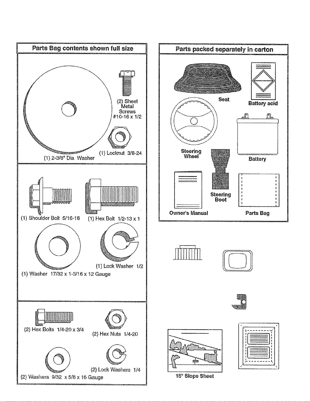
CONTENTS OF HARDWARE PACK
Parts bag contersts not shown fyil size
Steerina
Wheel
Steering Wheel
Adapter
Insert
HL
w
Steering
Bushing
< (2) Keys
BaHery Caps
and Instructions
Page 7
ASSEMBLY
Your new tractor has been assembled at the factory with exception of those parts left unassembled for shipping purposes.
To ensure safe and proper operation of your tractor all parts and hardware you assembJe must be tightened securely. Use
the correct tools as necessary to insure their proper tightness
TOOLS REQUIRED FOR ASSEMBLY
A socket wrench set will make assembly easier. Standard
wrench sizes are listed,
(1) 5/16" wrench
(2) 7/16" wrenches
(1) 1/2" wrench
(1) 9/16" wrench
When right and left hand is mentioned in this manual, it
means when you are in the operating position (seated
behind the steering wheel).
TO REMOVE TRACTOR FROM CARTON
UNPACK CARTON
• Remove all accessible loose parts and parts cartons
from cation (See page 6),
• Cut along lines on carton, from top to bottom, all four
comers of carton and lay panels flat.
• Check for any additional loose parts or cartons and
remove.
3/4" wrench
Tire pressure gauge
Screwdriver
Utility knife
BEFORE ROLLING TRACTOR OFF SKID
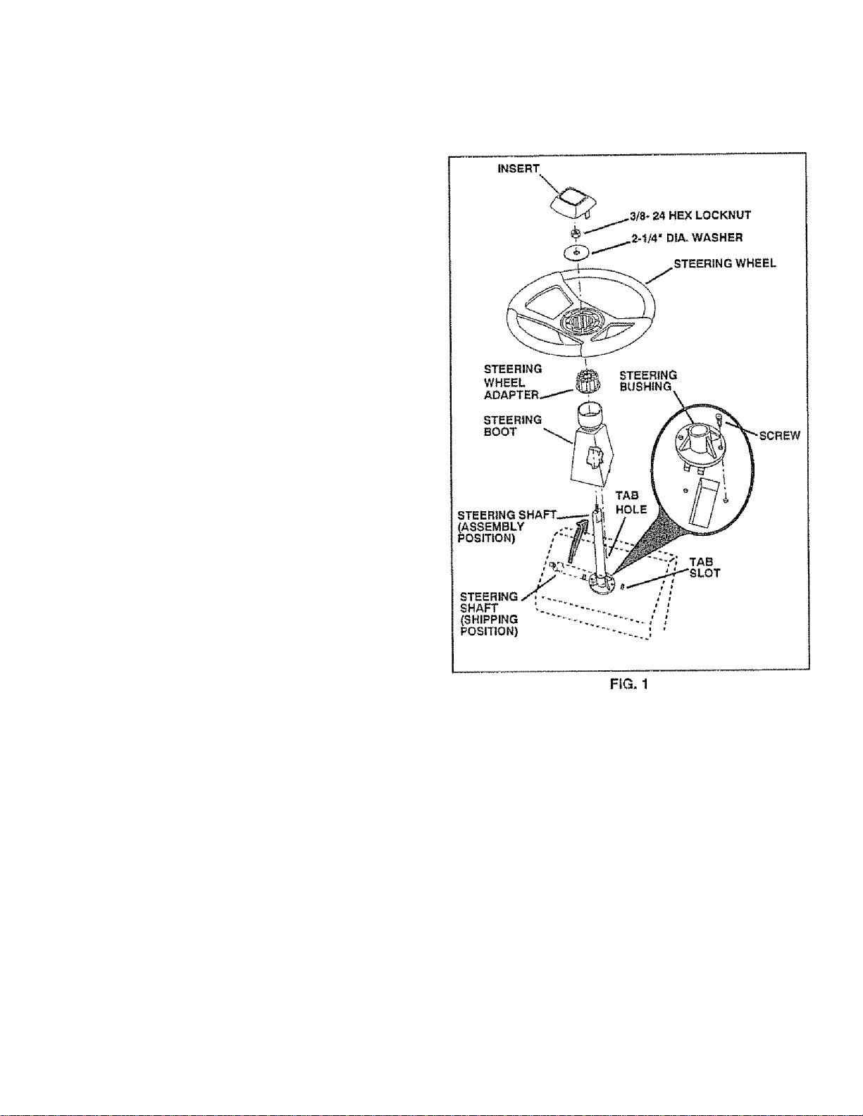
ATTACH STEERING WHEEL (See Fig. 1)
Slide the steering bushing over the steering shaft.
Raise steering shaft forward until screw holes in dash
line up with steering bushing. Install two (2) sheet
metai screws and tighten securely.
Position steering boot over steering shaft.
Place tabs of steering boot over slots in dash and push
down to secure.
Slide steering wheel adapter onto upper steering shaft.
Position front wheels of the tractor so they are pointing
straight forward.
Position steering wheel so cross bars are horizontal
(left to fight) and slide onto adapter.
Assemble large flat washer and 3/8-24 hex locknut and
tighten securely.
Snap insert into center of steering wheel.
Remove protective plastic from tractor hood and grill.
IMPORTANT: CHECK FOR AND REMOVE ANY
STAPLES
TRACTOR IS TO ROLL OFF SKID.
m
SKID THAT MAY PUNCTURE TIRES WHERE
(80® Fig. 6)
• Raise attachment lift lever to its highest position.
• Release parking brake by depressing clutch/brake
pedal.
■ Place gearshift iever in "NEUTRAL" position.
• Roll tractor backwards off skid.
• Remove banding holding discharge guard up against
tractor.
Page 8
ASSEMBLY
HOW TO SET UP YOUR TRACTOR
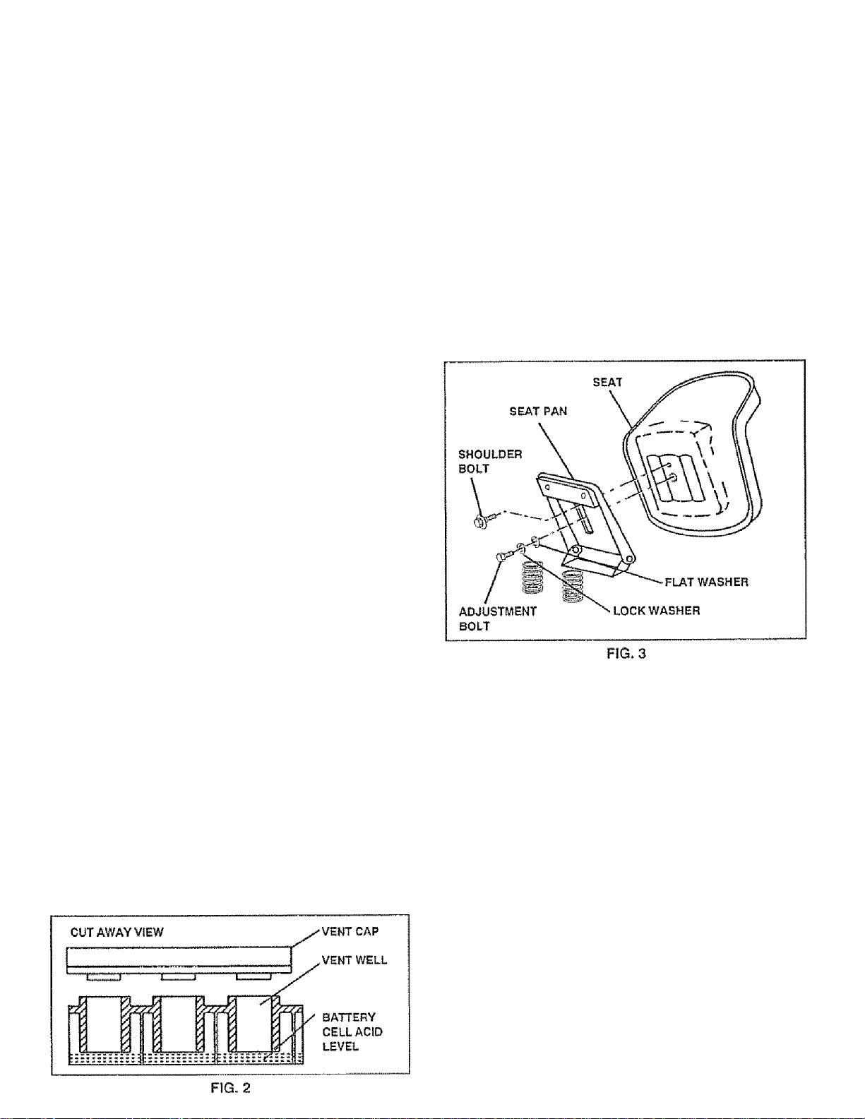
PREPARE BATTERY (See Fig. 2)
CAUTION; Wear eye and face shield.
Wash hands or clothing immediately If
accidentally in contact with battery acid.
/ -ff 1 * ■' »
Your tractor has a battery charging system which is suffi
cient for norma! use. However, periodic charging of the
battery with an automotive charger will extend its life.
• See instructions packed with vent caps In parts bag.
• Fill battery with acid. Fill each cell untii it reaches the
bottom of the vent weils. Do not overfill.
• Allow battery to stand and settle for at least thirty
minutes. After standing, check the !eve! of acid. If
below the vent wells, add more acid untii the correct
ievel is reached.
While battery is standing (after adding acid) and later, while
battery is being charged, continue with assembly of tractor.
IMPORTANT: TO MAXIMIZE THE LIFE OF YOUR
BATTERY, IT IS NECESSARY THAT THE BATTERY BE
CHARGED BEFORE USE FAILURE TO CHARGE
BATTERY GAN RESULT IN A SHORTENED BATTERY
LIFE
• Charge battery at a rate of 6 amperes for 1 hour. Use
a 12 volt battery charger. Observe all safety precautions
required for battery charging,
‘ Check the acid level after the battery is charged, If the
acid has fallen below the correct level, add distilled or
iron free water.
• Install the vent caps to cover the vent wells. Wash the
top of the battery with water to remove any acid, then
wipe dry.
« Check battery case for leakage to make sure that no
damage has occurred in handling. '
• Dispose of excess battery acid. Neutralize acid for
disposal by adding it to lour inches of water in a five
gallon plastic container. Stir with a wooden or plastic
paddle while adding baking soda until the addition of
more soda causes no more foaming.
» Foliow instructions on how to install battery.
Do not smoke. Fumes from charged
battery acid are explosive.
Read the Instructions Included with the
battery vent caps. Always wear gloves,
clothing and goggles to protect your
hands, skin and eyes.
INSTALL SEAT (See Fig. 3)
Adjust seat before tightening adjustment bolt.
“ Remove cardboard packing on seat pan,
« Place seat on pan and assemble shoulder bolt.
* Assemble adjustment bolt, lock washer and flat washer
loosely. Do not tighten,
* Tighten shoulder bolt securely,
“ Lower seat into operating position and sit on seat.
• Slide seat until a comfortable position is reached which
allows you to press dutch/brake pedal all the way down
(See Fig, 6).
• Get off seat without moving its adjusted position.
« Raise seat and tighten adjustment boit securely.
CHECK TIRE PRESSURE
The tires on your tractor were overinflated at the factory for
shipping purposes. Correct tire pressure is important for
best cutting performance,
*■ Reduce tire pressure PSI shown in "PRODUCT
SPECiFiCATION on page 3 of this manual.
CHECK DECK LEVELNESS
For best cutting results, mower housing should be properly
leveled. See "TO LEVEL MOWER HOUSING" in the
Service and Adjustments section of this manual.
CHECK FOR PROPER POSITION OF ALL
RPM TC
O&L* I O
See the figures that are shown for replacing motion and
mower blade drive belts in the Service and Adjustments
section of this manual. Verify that the belts are routed
correctly,
CHECK BRAKE SYSTEM
After you learn how to operate your tractor, check to see
that the brake is properly adjusted. See "TO ADJUST
BRAKE" in the Service and Adjustments section of this
manual.
8
Page 9
ASSEMBLY
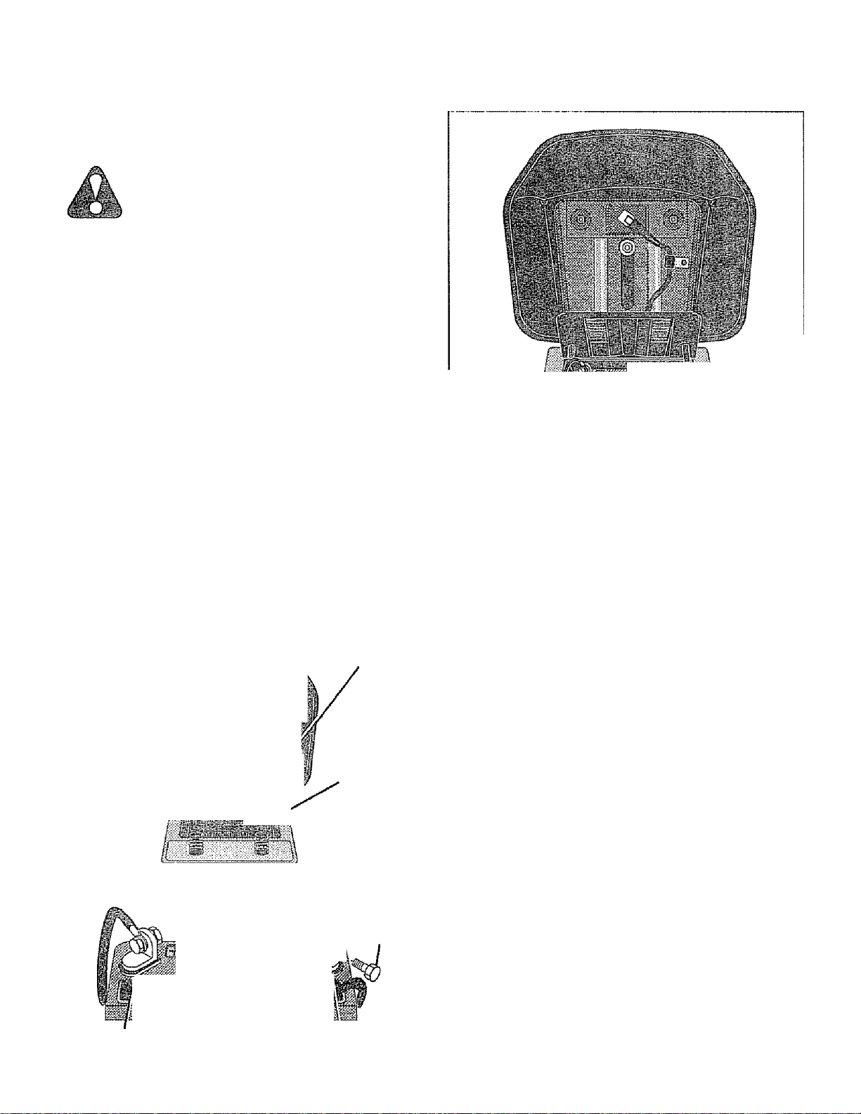
INSTALL BATTERY (See Figs. 4 & 5)
CAUTION: Do not short battery termi
nais. Before installing battery, remove
metal bracelets, wnstwatcn bands,
rings, etc.
Positive terminal must be connected
first to prevent sparking from acciden
tal groundirig.
* Lift seat to raised position.
» Open battery box door
” Lower battery into battery box with battery terminals
toward front of tractor,
» Be sure battery drain tube is attached to battery box
® First connect RED battery cable to positive (4) battery
terminal with hex bolt, flat washer, lock washer and hex
nut as shown. Tighten securely
0 Connect BLACK grounding cable to negative (-) bat
tery terminal with remaining hex bolt, fiat washer, lock
washer and hex nut. Tighten securely,
® Close battery box door.
Open battery box door for:
® Inspection for secure connections (to tighten hard
ware).
« Inspection for corrosion.
e Testing battery
® Jumping (if required),
® Periodic charging.
BATTERY
BOX DOOR
POSITIVE
(RED)
^^/VDLE
ci. :-i ."ï2-
LOCK WASHER
HEX NUT-
, .FLAT
^ \ /WASHER
NEGATIVE
(BLACK)
CABLE
HEX
BOLT
■>—1 -P''-;m
VENT CAPS
FIG. 5
^CNECKUST
q£PORE you operate and enjoy your new
jfq^CTOR, WE WISH TO assure tha t you receive
THE BEST PERFORMANCE AND SA TISFACTION FROM
THIS QUALITY PRODUCT
PLEASE REVIEW THE FOLLOWING CHECKLIST
/ All assembly instructions have been completed.
/ No remaining loose parts in carton.
/ Battery is properly prepared and charged. (Minimum
1 hour at 6 amps|,
/ Seat is adjusted comfortably and tightened securely
/ Ali tires are properly inflated. (For shipping purposes,
the tires were over-inflated at the factory),
/ Be sure mower deck is properly leveled side-to-side/
front-to-rear for best cutting results. (Tires must be
properly inflated for leveling)
/ Check mowerand drive belts. Be sure they are routed
properly around pulleys and inside all belt keepers.
V Check wiring. See that all connections are still secure
and wires are properly damped.
WHILE LEARNING HOWTO USE YOUR TRACTOR, PAY
EXTRA ATTENTION TO THE FOLLOWING IMPORTANT
ITEMS:
/ Engine oil is at proper level,
/ Fuel tank is tied with fresh, dean, regular unleaded
POSITIVE (+} TERMINAL
FIG. 4
NEGATIVE (.) TERMINAL
/ Become familiar with ali controls - their location and
function. Operate them before you start the engine.
/ Be sure brake system is in safe operating condition.
9
Page 10
OPERATION
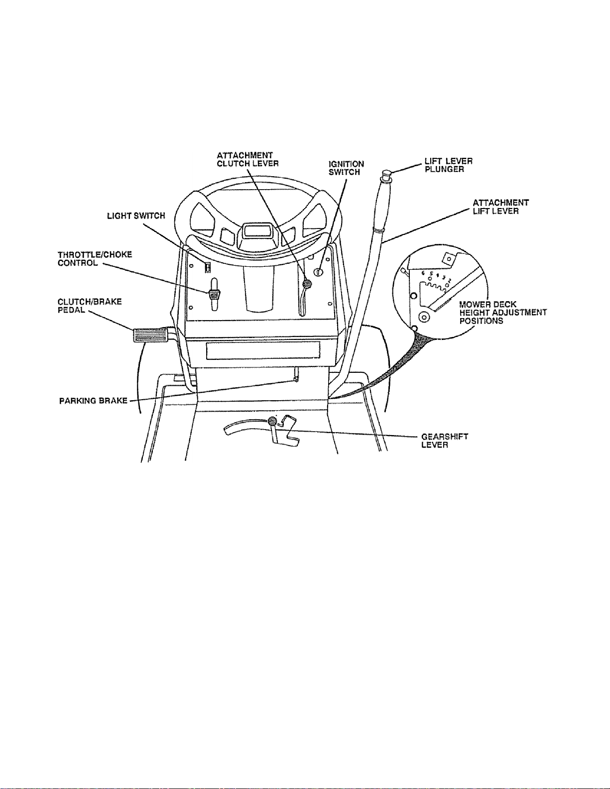
KNOW YOUR TRACTOR
READ THIS OWNER'S MANUAL AND SAFETY RULES BEFORE OPERATING YOUR TRACTOR
Gomparetheiliustratlonswithyouriractortofamiliarize yourselfwith the locations ofvariouscontrolsand adjustments. Save
this manual for future reference.
Sears tractors conform to the safety standards of the American National Standards Institute.
THROTTLE/CHOKE CONTROL; Used for starting and
controlling engine speed.
CUUTCH/BRAKE PEDAL: Used for declutching and
braking the tractor and starting the engine.
PARKING BRAKE: Locks clutch/brake pedal into the
brake position.
IGNITION SWITCH; Used for starting and stopping the
engine.
GEARSHIFT LEVER: Selects the speed and direction of
tractor.
FIG. 6
LIGHT SWITCH: Turns the headlights on and off.
ATTACHMENT CLUTCH LEVER; Used to engage the
mower blades, or other attachments mounted to your
tractor.
ATTACHMENT LIFT LEVER; Used to raise, lower, and
adjust the mower deck or other attachments mounted to
your tractor.
LIFT LEVER PLUNGER; Used to release attachment lift
lever when changing its position.
10
Page 11
OPERATION
your tractor or performing any adjustments or repairs. We recommend wide vision safety
mask for over the spectacles or standard safety glasses, available at Sears Retail or
Catalog stores.
HOW TO USE YOUR TRACTOR
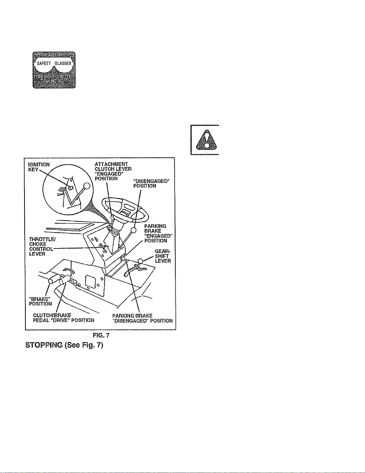
TO SET PARKING BRAKE (See Fig. 7)
a Depress clutch/brake pedal into full "BRAKE" position
and hold.
» Place parking brake lever in" ENGAG ED" position and
release pressure from cl utch/brake pedal Pedal should
remain in "Bf=LAKE" position . Make sure parking brake
will hold tractor secure.
NOTE: Under certain conditions when tractor is standing
idle with the engine running, hot engine exhaust gases may
cause "browning" of grass. To euminate this possibility,
always stop engine when stopping tractor on grass areas.
CAUTION: Always stop tractor com
pletely, as described above, before leav
ing the operator's position; to empty
grass catcher, etc.
TO USE THROTTLE CONTROL (See Fig. 7)
Always operate engine at full throttle.
0 Operating engine at less than full throttle reduces the
battery charging rate.
« Full throttle offers the best bagging and mower per
formance.
TO MOVE FORWARD AND BACKWARD (See
Fig. 6)
The direction and speed of movement is controlled by the
gearshift lever
0 Start tractor with clutch/brake pedal depressed and
gearshift lever in “NEUTRAL" position.
» Move gearshift lever to desired position.
" Slowly release clutchAirake peda! to start movement,
IMPORTANT: BRING TRACTOR TO A COMPLETE STOP
BEFORE SHIFTING OR CHANGING GEARS. FAILURE
TO DO SO v/ill shortsn the ushful liff of vour
TRANSAXLE-
MOWER BLADES ■
* Move attachment clutch lever to "DISENGAGED" po
sition.
GROUND DRIVE » Depress clutch/brake pedal into full "BRAKE" position,
<• Move gearshift lever to "NEUTRAL" position,
ENGINE * Move throttle control to "SLOW" position.
NOTE; Failure to move throttle control to "SLOW" position
and allowing engine to idle before stopping may cause
engine to "backfire".
® Turn ignition key to "OFF" position and remove key.
Always remove key when leaving tractor to prevent
unauthorized use,
o Never use choke to stop engine.
TO ADJUST MOWER CUTTING HEIGHT (See
Fig. 6) '
The position of the attachment lift lever determines the
cutting height
» Grasp lift lever.
» Press plunger with thumb and move lever to desired
position.
The cutting height range Is approximately 1-1/2 to 4". The
heights are measured From the ground to the blade tip with
the engine not running. These heights are approximate
and may vary depending upon soil conditions, height of
grass and types of grass being mowed.
e The average lawn should be cut to approximately
2-1/2 inches during the cool season and overS inches
during hot months. For healthier and better looking
lawns, mow often and after moderate growth.
» For best cutting performance, grass over 6 inches in
height should be mowed twice. Make the first cut
relatively high; the second to desired height.
11
Page 12
OPERATION
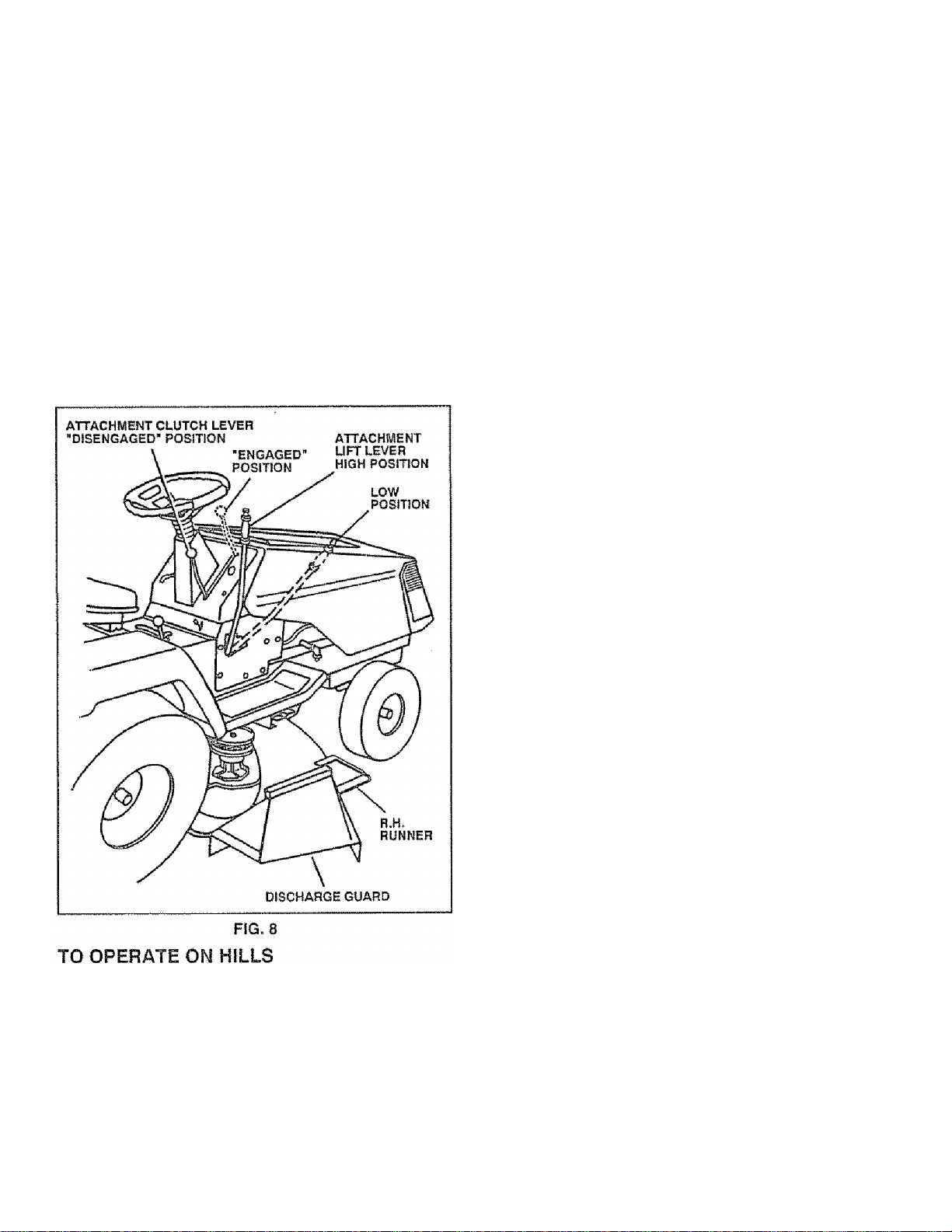
TO OPERATE MOWER (See Fig. 8)
Yourtractor Is equipped with an operator presence sensing
switch Any attempt by the operator to leave the seat with
the engine running and the attachment clutch engaged will
shut off the engine.
• Select desired height of cut,
• Engage mower by slowly moving attachment clutch
lever to "ENGAGED" position.
• TO STOP MOWER • Move attachment clutch lever to
"DISENGAGED" position.
CAUTION: Do not operate the mower
without either the entire grass catchefj
on mowers so equipped, or the dis
charge guard in place.
CAUTION: Do not drive up or down
. hills with slopes greater than 15* and
across any slope.
» If stopping is absolutely necessary, push clutch/brake
pedal quickly to brake position and engage parking
brake.
• Move gearshift lever to l st gear and be sure you have
allowed room for tractor to roll slightly as you restart
movement.
■ To restart movement, slowly release parking brake and
clutch/brake pedal-
• Make all turns slowly.
TO TRANSPORT
» Raise attachment lift control to highest position
» When pushing or towing your tractor, be sure gearshift
iever is in "NEUTRAL" position.
• Do not push or tow tractor at more than five (5) MPH.
BEFORE STARTING THE ENGINE
CHECK ENGINE OH- LEVEL (See Fig. 13)
■ The engine in your tractor has been shipped from the
factory already filled with summer weight oil.
• Check engine oil with tractor on level ground
• Remove oil fill dipstick and wipe clean, replace and
screw cap tight, wait for a few seconds, remove and
read oil level If necessary, add oil until "FULL" mark
on dipstick is reached. Do not overfill,
' For cold weather operation you should change oil for
easier starting (see "OIL VJSGOSITY CHART" in the
Customer Responsibilities section of this manual).
“ To change engine oil, see the Customer Responsibili
ties section in this manual
ADD GASOLINE
“ Fill fuel tank. Use fresh, clean, regular unleaded
gasoline. (Use of leaded gasoline will increase carbon
and lead oxide deposits and reduce valve life).
IMPORTANT: WHEN OPERATING IN TEMPERATURES
BELOW32‘=F(0“G), USE FRESH, CLEAN WINTER GRADE
GASOLINE TO HELP INSURE GOOD COLD WEATHER
STARTING.
WARNING: Experience indicates that alcohol blended
fuels (called gasohol or using ethanol or methanol) can
attract moisture which leads to separation and formation of
acids during storage. Acidic gas can damage the fuel
system of an engine while in storage. To avoid engine
problems, the fuel system should be emptied before stor
age of 30 days or longer. Drain the gas tank, start the
engine and let it run until the fuel lines and carburetor are
empty. Use fresh fuel next season. See Storage instruc
tions for additional information. Never use engine or
carburetor cleaner products in the fuel tank or permanent
damage may occur
Choose the slowest speed before starting up or down
hills.
Avoid stopping or changing speed on hills.
if slowing is necessary, move throttle control lever to
slower position.
12
ik
CAUTION: Fill to bottom of gas tank
filler neck. Do not overfill. Wipe off any
spilled oil or fuel. Do not store, spill or
use gasoline near an open flame.
Page 13
OPERATION
TO START ENGINE (See Fig. 7)
When starting engine for the first time or if engine has
run out of fuel, it will take extra cranking time to move
fael from the tank to the engine.
‘ Depress the clutch/brake pedal and set the parking
brake,
• Place gearshift lever in "NEUTRAL" position.
• Move attachment clutch to "DISENGAGED" position,
• Move throttfe control lever to "CHOKE" position for
cold engine start. For warrn engine start, move
throttle control to "FAST" position.
• Turn ignition key clockwise to “StarT" position and
release key as soon as engine starts. Do not run
starter continuously for more than fifteen seconds
per minute, if engine does not start after several
attempts, move throttle controi to "FAST" position,
wait a few minutes and try again.
• When engine starts, move throttie control to desired
position.
• Allow engine to warm up for a few minutes before
engaging drive or attachment clutch.
NOTE: If at a high altitude (above 3000 feet) or in cold
temperatures (below 32" F), the carburetor fuel mixture
may need to be adjusted for best engine performance.
See "TO ADJUST CARBURETOR" in the Service and
Adjustments section of this manual,
Drive so that clippings are discharged onto the area
that has been cut. Have the cut area to the right of
the tractor. This will result in a more even distribu
tion of clippings and more uniform cutting.
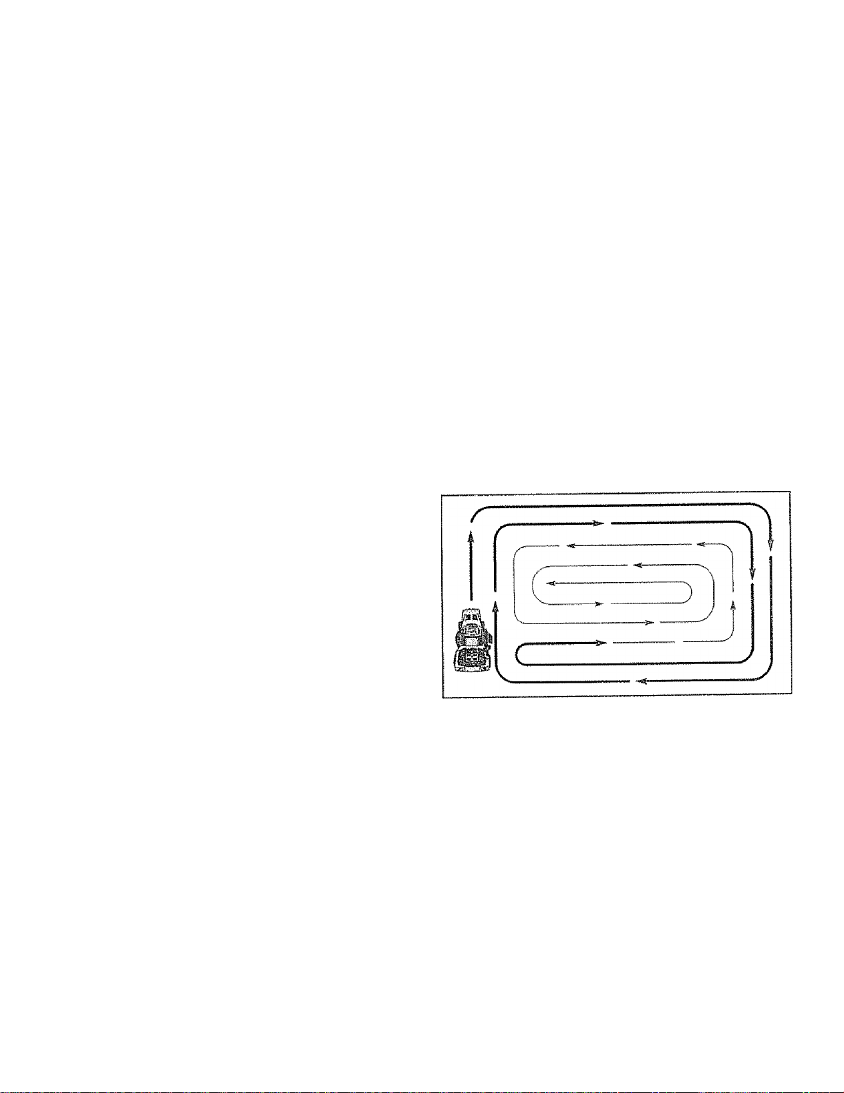
When mowing large areas, start by turning to the
right so that clippings will discharge away from
shrubs, fences, driveways, etc. After one or two
rounds, mow in the opposite direction making left
hand turns until finished (See Fig. 9).
If grass is extremely tall, it should be mowed twice
to reduce load and possible fire hazard from dried
clippings. Make first cut reiativeiy high; the second
to the desired height
Do not mow grass when It is wet. Wet grass will
plug mower and leave undesirable clumps. Allow
grass to dry before mowing.
Always operate engine at full throttle when mowing
to assure better mowing performance and proper
discharge of material. Regulate ground speed by
selecting a low enough gear to give the mower
cutting performance as well as the quality of cut
desired.
When operating attachments, select a ground speed
that will suit the terrain and give best performance of
the attachment being used.
MOWING TIPS
• Tire chains cannot be used when the mower hous
ing is attached to tractor.
• Mower should be properly leveled for best mowing
performance. See "TO LEVEL MOWER HOUSING"
m the Service and Adjustments section of this
manual.
• Use the runner on the right hand side of mower as
a guide. The blade cuts approximately an inch
outside the runner (See Fig. 8)
• The left hand side of mower should be used for trim
ming.
FÎG. 9
13
Page 14
CUSTOMER RESPONSIBILÎTIES
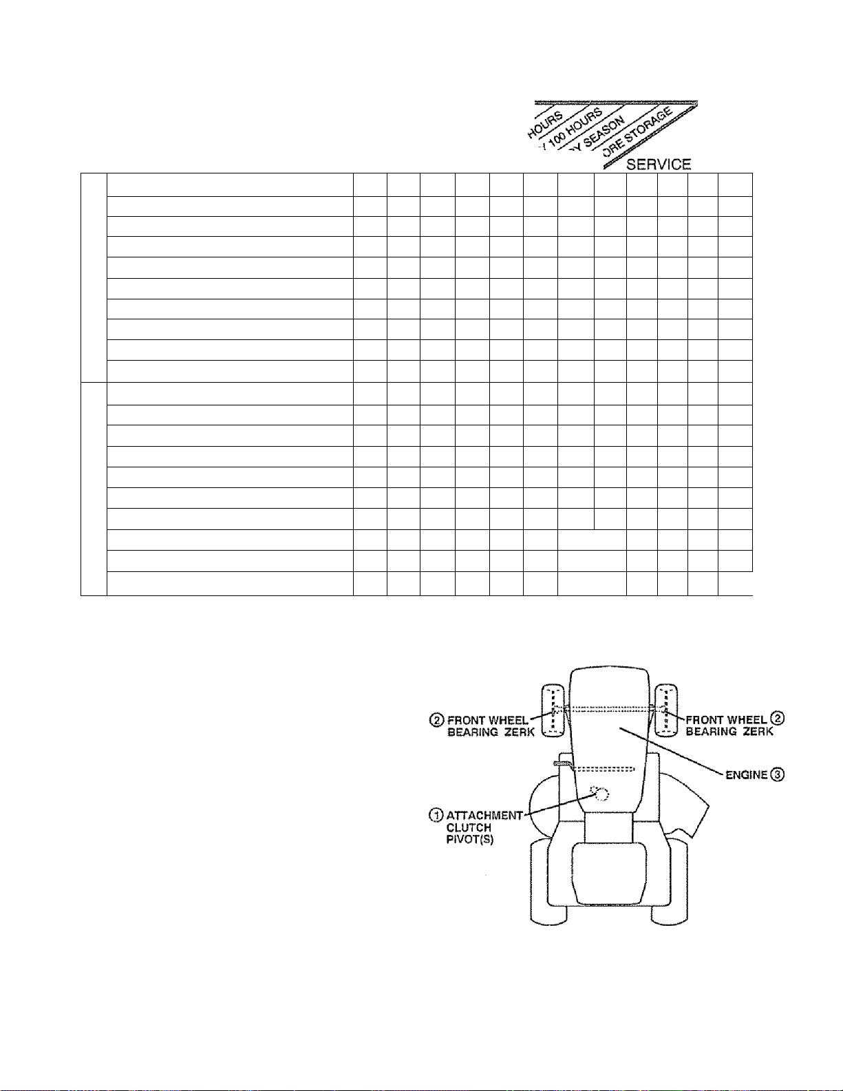
MAINTENANCE SCHEDULE
FILL IN DATES
AS YOU COMPLETE
REGULAR SERVICE
Check Brake Operation j ^
Check Tire Pressure | ^
T
Check for Loos© Fasteners 11/'
R
Sharpen/Replace Mower Blades |
A
Lubrication Chart |
C
Check Battery Level/Rechargs j
T
Clean Battery and Terminals |
0
R
Check Transmission Cooling |
Adjust Blade Belt(s) Tension |
Adjust Motion Drive Belt(s) Tension |
Check Engine Oil Level | ^
Change Engine Oil |
Clean Air Filter j
E
Clean Air Screen j
N
Inspect Muffler/Spark Arrester |
G
1
Replace Oil Filter (If equipped) |
N
Clean Engine Cooling Fins |
Ê
Replace Spark Plug j
Replace Air Filter Paper Cartridge j
Replace Fuel Filter j
L
1 - Change more often when operating under a heavy load or In high ambient tempetatures
E • Service mors ofisn when operating In dirty or dusty conditions
GENERAL RECOMMENDATIONS
The warranty on this tractor does not cover items that have
been subjected to operator abuse or negligence. To
receive full value from the warranty, operator must main
tain tractor as instructed in this manual.
Some adjustments will need to be made periodically to
properly maintain your tractor.
All adjustments In the Service and Adjustments section of
this manual should be checked at least once each season.
• Once a year you should replace the spark plug, clean
or replace air filter, and check blades and belts for
wear. A new spark plug and clean air filter assure
proper air-fuel mixture and help your engine run better
and last longer.
s/
f/
i/4
«/
1/
1/ 1/
1/
✓
1^2.3
✓ 2
|/
§/*5
1/5
|/
ls^.2
2
1/
1/
1/
3 ■ 11 equipped with oil ffiler, change oil every SO hOdfS
4 - Replace blades more often when mowing In sandy soil
5 - if equipped with adjustable system
LUBRICATION CHART
DATES
1
BEFORE EACH USE
• Check engine oil level,
• Check brake operation.
’ Check tire pressure.
• Check for loose fasteners.
® SAE 30 OR 10W30 MOTOR OIL API - SG
d) general purpose grease
d) REFER TO CUSTOMER RESPONSIBIUTIES “ENGINE” SECTION
IMPORTANT: DO NOT OIL OR GREASE THE PIVOT POINTS
WHICH HAVE SPECIAL NYLON BEARINGS VISCOUS LUBRI
CANTS WILL ATTRACT OUST AND DIRT THAT WILL SHORTEN
THE LIFE OF THE SELF-LUBRICATING BEARINGS, IF YOU
feel they must be LUBRICATED, USE ONLY A DRY. POW
DERED GRAPHITE TYPE LUBRICANT SPARINGLY,
14
Page 15
CUSTOMER RESPONSIBILITIES
TRACTOR
Always observe safety rules when performing any mainte
nance.
BRAKE OPERATION
(See 'TO ADvJUST BRAKE" in Service and Adjustments
section of this manual).
TIRES
• Maintain proper air pressure in all tires (See "PROD
UCT SPECIFICATIONS" on page 3 of this manual),
• Keeptires free of gasoline, oil, or insect control chemi
cals which can harm rubber.
• Avoid stumps, stones, deep ruts, sharp objects and
other hazards that may cause tire damage.
BLADE CARE
For best results mower blades must be kept sharp. The
blades can be sharpened with a file or on a grinding wheel.
We suggest they be sharpened or replaced ater every 25
hours of mowing. Check blades more often if mowing in
sandy conditions.
• Do not attempt to sharpen blades while they are on the
mower.
• Replace bent or damaged blades.
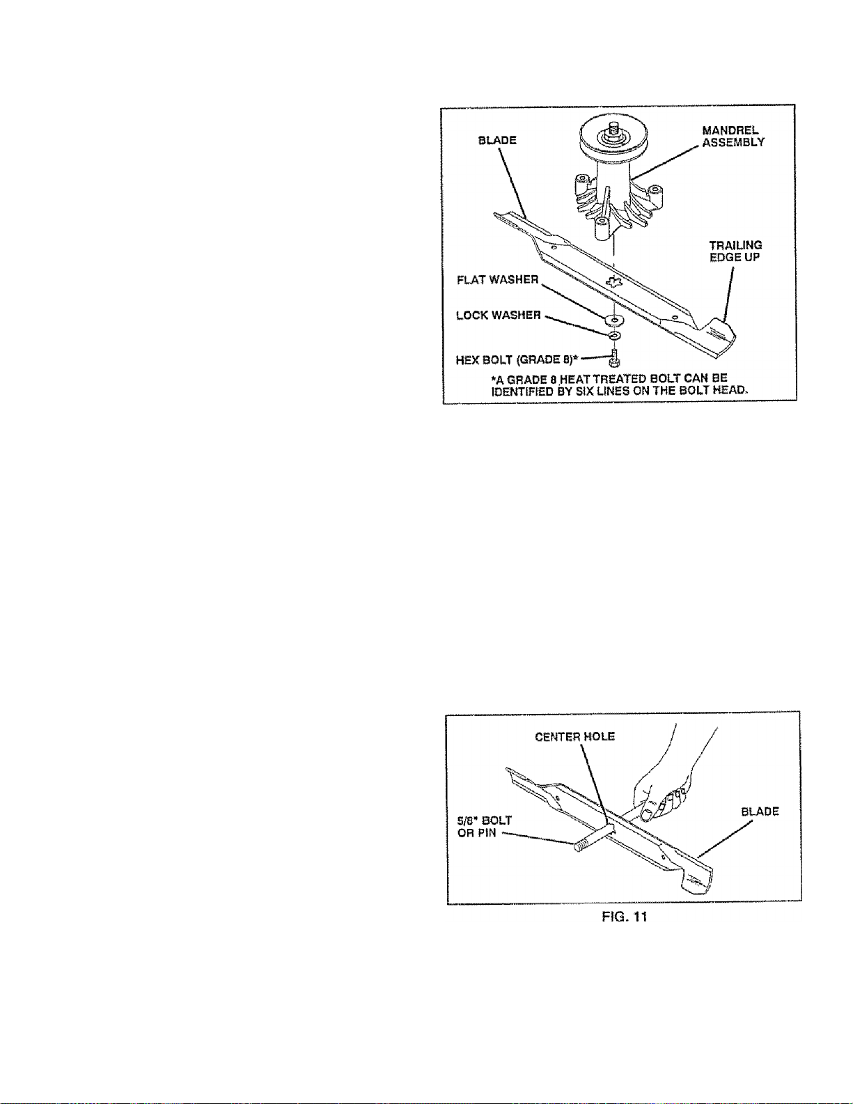
BLADE REMOVAL (See Fig. 10)
• Raise mower to highest position to allow access to
blades.
• R emove h ex b o It, i o ck washer and flat was h er securing
blade.
' Install new or resharpened blade with trailing edge up
towards deck as shown,
' Reassemble hex bolt, lock washer and flat washer in
exact order as shown,
• Tighten bolt securely (30-35 Ft Lbs. torque).
IMPORTANT^ BLADE BOLT IS GRADES HEAT TREATED-
FIG. 10
TO SHARPEN BLADE (See Fig. 11)
Care should be taken to keep the blade balanced. An
unbalanced blade will cause excessive vibration and even
tual damage to mower and engine.
• The blade can be sharpened with a file or on a grinding
wheel. Do not attempt to sharpen while on the mower.
• To check blade balance, you will need a 5/8" diameter
steel bolt, pin, or a cone balancer. (When using a cone
balancer, follow the instructions supplied with bal
ancer).
• Slide blade on to an unthreaded portion of the steel boit
or pin and hold the bolt or pin parallel with the ground,
if blade is balanced, it should remain in a horizontal
position, if either end of the blade moves downward,
sharpen the heavy end until the blade is balanced,
NOTE: Do not use a nail for balancing blade. The lobes of
the center hole may appear to be centered, but are not.
15
Page 16
CUSTOMER RESPOMSiBILITIES
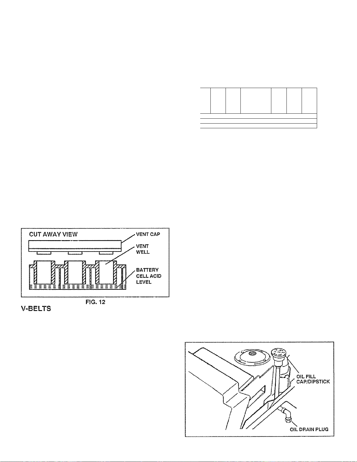
BATTERY (See Fig. 12)
Your unit has a battery charging system which is sufficient
for normal use. However, periodic charging of the battery
with an automotive charger wiil extend it's life.
• Acid solution level in each battery ceil should be even
with bottoms ofvent weils. Add only distilled or iron free
water if necessary. Do not overfill.
• Keep battery and terminals clean.
• Keep battery bolts tight.
• Keep vent caps tight and small vent holes in caps open,
" Recharge at 6 amperes for 1 hour,
TO CLEAN BATTERY AND TERMINALS -
Corrosion and dirt on the battery and terminals can cause
the battery to “leak" power.
• Remove terminal guard,
• Disconnect BLACK battery cable first then RED bat
tery cable and remove battery from tractor,
• Wash battery with solution of four tablespoons of
bak ing soda to one g all on of water. Be careful not to get
the soda solution into the cells,
• Rinse the battery with plain water and dry.
• Clean terminais and battery cable ends with wire brush
until bright
- Coat terminals with grease or petroleum Jelly.
• Reinstaii battery (See "iNSTALL BATTERY" in the
Assembly section of this manuai).
Check V-belts for deterioration and wear after 100 hours of
operation and replace if necessary. The belts are not
adjustable. Replace belts if they begin to slip from wear.
TBANSAXLE COOLING
Keep transaxle tree from build-up of dirt and chaff which
can restrict cooling.
ENGINE
LUBRICATION
Only use high quality detergent oil rated with API service
classification SG. Select the oil's SAE viscosity grade
according to your expected operating temperature.
SAg VSSCOSiTV GRADES
*i] f ,
•'..'■ r-r-g:
h
i*F
‘¿S' su* 32* -4 0*
-asr
I TEMPERATURE RANGE ANTICIPATED BEFORE NEXT OIL CHANGE
■ 20* -ia* D* 10* 20* so
6Q»
10TE: Although muiti-viscosity oils (5W30,10W30, etc.)
improve starting in cold weather, these multi-viscosity oils
will result in increased oil consumption when used aboe
32“C. Check your engine oil level more frequently to avoid
possible engine damage from running low on oil
Change the oil after the first two hours of operation and
every 25 hours thereafter or at least once a year if the
tractor is not used for 25 hours In one year.
Check the crankcase oil level before starting the engine
and after each eight (8) hours of continuous use. Tighten
oil fiii cap/dipstick securely each time you check the oil
level.
TO CHANGE ENGINE OIL (See Fig. 13)
Determine temperature range expected before oil change.
All oil must meet API service classification SG.
Be sure tractor is on level surface.
Oil will drain more freely when warm.
Catch oil in a suitable container.
Remove oil fill dipstick. Be careful not to allow dirt to
enter the engine when changing oil.
Remove drain plug
After oil has drained completely, replace oil drain plug
and tighten securely.
Refill engine with oil through oil fill dipstick tube. Pour
slowly. Do not overfill. For approximate capacity see
"PRODUCT SPECIFICATIONS" on page 3 of this
manual.
Use gauge on oil fill dipstick for checking level. Be sure
dipstick cap is tightened securely for accurate reading.
Keep oil at "FULL" line on dipstick.
1«’
• 40*
16
FIG. 13
Page 17

CUSTOMER RESPONSIBILITIES
AIR FILTER FOAM PRE-CLEANER (See Fig.
14)
Your engine will not run properly and may be damaged by
using a dirty air filter. Clean the foam pre-cleaner element
after every 25 hours of operation, mors often if used in very
dusty, dirty conditions,
• Remove knob and cover.
■ Remove cartridge nut and replace cartridge.
• Reassembie and tighten securely,
NOTE: Do not attempt to clean or oil the paper cartridge.
Replace paper cartridge once a year or after every 100
hours of operation, more often if used in very dusty, dirty
conditions,
• Wash foam pre-cleaner in liquid detergent and water.
• Wrap foam pre-cleaner in doth and squeeze dry.
• Lightly coat foam pre-cleaner with clean engine oil.
Squeeze In towel to remove excess oil. Do not satu
rate.
• Install foam pre-cleaner over paper cartridge.
• Reassembie cover and secure with knobs.
Inspect and replace corroded muffler and spark arrester (if
equipped) as it could create a fire hazard and/or damage.
AIR SCREEN (See Fig. 15)
The engine air screen must be kept free of dirt and chaff to
prevent engine damage from overheating. Clean with a
wire brush or compressed air to remove dirt and stubborn
dried gum fibers.
ENGINE COOLING FINS (See Fig. 15)
Remove any dust, dirt or oil from engine cooling fins to
prevent engine damage from overheating. '
• Remove oil fill dipstick and cover opening to prevent
entry of dirt.
• Remove screws from blower housing and lift housing
off engine.
• Remove the screws securing the starter housing and
lift housing off engine.
• Use compressed air or stiff bristle brush to thoroughly
dean engine cooling fins.
• To reassemble, reverse above procedure.
SPARK PLUGS
Replace spark plugs at the beginning of each mowing
season or after every 100 hours of operation, whichever
comes first Spark plug type and gap setting are shown in
"PRODUCT SPECIFICATIONS" on page 3 of this manual.
IN-LINE FUEL FILTER (See Fig. 16)
The fuel filter should be replaced once each season. If fuel
filter becomes dogged, obstructing fuel flow to carburetor,
replacement is required.
• With engine cool, remove filter and plug fuel line
sections.
• Place new fuel filter in position in fuel line.
• Be sure there are no fuel line leaks and damps are
properly positioned.
• immediately wipe up any spilled gasoline
FIG, 16
CLEANING
• Clean engine, battery, seat, finish, etc. of all foreign
matter,
• Keep finished surfaces and wheels free of all gasoline,
oil, etc.
• Protect painted surfaces with automotive type wax.
We do not recommend using a garden hose to clean your
tractor unless the electrical system, muffler, air filter and
carburetor are covered to keep water out. Water in engine
can result in a shortened engine life.
17
Page 18

SERVICE AND ADJUSTMENTS
CAUTION; BEFORE PERFORMING ANY SERVICE OR ADJUSTMENTS:
. Depress clutch/brake pedal fully and set parking brake.
• Place gearshift lever in "NEUTRAL'* position.
• Place attachment clutch in 'DISENGAGED'* position.
« Turn ignition key "OFF” and remove key.
• Make sure the blades and all moving parts have completely stopped.
• Disconnect spark plug wire from spark plug and place wire where it cannot come in contact with
plug.
TRACTOR
TO REMOVE MOWER (See Fig. 17)
Mower will be easier to remove from the right side of tractor.
• Place attachment clutch in "DISENGAGED" position.
• M ove attach m ent lift I ever forward to lower mower to its
lowest position.
• Roll belt off engine puliey.
• Disconnect clutch rod from clutch iever by removing
retainer spring.
« Disconnect suspension arms from rear deck brackets
by removing retainer springs.
• Disconnect front links from deck by removing retainer
springs.
• Raise lift lever to raise suspension arms. Slide mower
out from under tractor.
IMPORTANT: IF AN ATTACHMENT OTHER THAN THE
MOWER IS TO BE MOUNTED TO THE TRACTOR, THE
R.H, AND L.H. SUSPENSION ARMS MUST BE REMOVED
FROM TRACTOR.
TO INSTALL MOWER {See Fig. 17)
• Raise attachment lift lever to its highest position.
• Slide mower under tractor with discharge guard to right
side of tractor.
• Lower lift iever to its lowest position.
’ Install mower in reverse order of removal instructions,
NOTE: The mower clutch rod has a trunnion that has been
preset at the factory for optimum mower performance. DO
NOT MOVE THE TRUNNION ON THE CLUTCH ROD. If
for any reason the trunnion has been moved on the clutch
rod, it must be reset to correct position (parallel with clutch
rod) and measure 10*11 /32" (Check dimension on edge of
flat work surface as shown).
Be sure to tighten trunnion nut securely against trunnion
after making any adjustments.
18
Page 19

SERVICE AND ADJUSTMENTS
TO LEVEL MOWER HOUSING
Adjust the mower while tractor is parked on level ground or
driveway. Make sure tires are properly inflated {See
"PRODUCT SPECIFICATIONS" on page 3). If tires are
over or under inflated, you will not properly adjust your
mower.
SIDE-TO-SIDE ADJUSTMENT (See Figs. 18 and 19) You will need two (2) standard 2x4 short pieces of wood
to make the following adjustment. Simitar blocks measur
ing 1-1/2" thick may also be used,
* Raise mower with attachment lift control to allow two
(2) 1 -1/2“ thick blocks to be placed under rear edge of
mower directly behind mandrels.
* Lower mower deck to its lowest height of cut position
fSee 'TO ADJUST MOWER CUTTING HEIGHT’ In
Operation section of this manual),
» On both sides of tractor, loosen, but do not remove, the
fasteners securing the adjustable pivot brackets to
frame. Both bracfets must be loose enough to move
freely.
» Pull down firmly on suspension arm to remove any
slack in pivot bracket and h>. id while tightening rear
fastener first to secure, Tighte, remaining fastener.
» Repeat procedure on other side of tractor.
« Raise mower with attachment lift control and remove
blocks from under mower.
FRONT-TO-BACK ADJUSTMENT (See Figs. 20 and 21) IMPORTANT; DECK MUST BE LEVEL SIDE-TO-SIDE, IF
THE FOLLOWING FRONT-TO-BACK ADJUSTMENT IS
NECESSARY, BE SURE TO ADJUST BOTH FRONT LINKS
EQUALLY SO MOWER WILL STAY LEVEL SIDE-TO-
jnc
S
To obtain the best cutting results, the mower housing
should be adjusted so that the front is approximately 1/4"to
3/4“ lower than the rear when the mower Is in its highest
position.
Check adjustment on right side of tractor. Measure dis
tance “D" directly in front and behind the mandrel at bottom
edge of mower housing as shown.
» Before making any necessaiy adjustments, check that
both front links are equal in length. Both links should
be approximately 10-3/8",
» If links are not equal in length, adjust one link to same
length as other link
» To lower front of mower loosen nut "E" on both front
links an equal number of turns.
* When distance “D“ is 1/4" to 3/4" lower at front than
rear, tighten nuts “F' against trunnion on both front
links.
<» To raise front of mower, loosen nut "F'from trunnion on
both front links. Tighten nut “E" on both front links an
equal number of turns.
« When distance "D" is 1/4“ to 3/4“ tower at front than
rear, tighten nut "F" against trunnion on bothfront links,
* Recheck side-to-side adjustment.
Page 20

SERVICE AND ADJUSTMENTS
TO REPLACE MOWER BLADE DRIVE BELT
(See Fig. 22)
The mower blade drive belt may be replaced without tools.
Park the tractor on level surface. Engage parking brake.
For assistance, there is a belt installation guide decal on the
mower housing.
DcLi HcMUVAL-
Place attachment clutch in "DISENGAGED" position-
Move attachment lift lever forward to lower mower to its
lowest position.
Roll belt off engine puiiey.
Disconnect R.H. suspension arm from reardeck bracket
by removing retainer spring.
Work belt off both mandrel pulleys and idler pulleys.
Pull belt away from mower.
BELT INSTALLATION -
install new belt in reverse order of removal,
Make sure belt is in all pulley grooves and inside ait belt
guides.
TO REPLACE MOTION DRIVE BELT (See
Fig. 24)
Park the tractor on level area. Engage parking brake.
For assistance, there is a belt installation guide decal on
bottom side of left footrest.
• Remove mower (See "TO REMOVE MOWER" in this
section of this manual),
• Remove belt from stationary idler and clutching idier.
• Remove belt from engine pulley.
• Roll belt over top of transaxle pulley.
• install new belt by reversing alsove procedure.
TO ADJUST BRAKE (See Fig. 23)
Your tractor is equipped with an adjustable brake system
which is mounted on the right side of the transaxle.
If tractor requires more than six (6) feet stopping distance
at high speed in highest gear, then brake must be adjusted.
• Depress clutch/brake pedal and engage parking brake.
• Measure distance between brake operating arm and
nut "A" on brake rod.
• if distance is other than 1-1/2", disengage parking
brake, loosen jam nut and turn nut "A" until distance
becomes 1-1/2”. Reiighten jam nut against nut "A".
• Engage parking brake and recheck distance,
• Road test tractor for proper stopping distance as stated
above. Readjust if necessary. If stopping distance is
sttil greater than six (6) feet in highest gear, further
maintenance is necessary. Contact your nearest au
thorized service center.
IIVIjaOFiTANT; REPLACE
IN THIS MANUAL,
20
ONLY WITH BELT LISTED
Page 21

SERVICE AND ADJUSTMENTS
TO ADJUST STEERING WHEEL ALIGNMENT
it steering wheel crossbars are not horizontal (left to right)
when wheels are positioned straight foward, remove steer
ing wheel and reassemble per instructions in the Assembly
section of this manual.
FRONT WHEEL TOE-IN/CAMBER
The front whee! toe-in and camber are not adjustable on
your tractor, if damage has occurred to affect the front
wheel toe-in or cambert contact your nearest authorized
service center.
TO REMOVE WHEEL FOR REPAIRS {See
Fig. 25)
• Biock up axle securely.
• Remove axle cover, retaining ring and washers to aliow
wheei removal {rear wheel contains a square key - Do
not lose)
• Repair tire and reassemble
• On rear wheels only; align grooves in rear wheel hub
and axle Insert square key.
• Replace washers and snap retaining ring securely in
axle groove,
• Replace axle cover -
TO START ENGINE WITH A WEAK BATTERY
(See Fig. 26)
CAUTION: Lead-acid batteries gener
ate explosive gases. Keep sparks, fiame
and smoking materials away from bat
A
If your battery is too weak to start the engine, it should be
recharged- If "jumper cables’* * are used for emergency
starting, follow this procedure:
IMPORTANT; YOUR TRACTOR IS EQUIPPED WTO A
12 VOLT NEGATIVE GROUNDED SYSTEM. THE OTHER
VEHICLE MUST ALSO BE A 12 VOLT NEGATIVE
grounded SYSTEM. DO NOT USE YOUR TRACTOR
BATTERY TO START OTHER VEHICLES.
TO ATTACH JUMPER CABLES -
• Connect each end of the RED cable to the POSITIVE
{4.) terminal of each battery, taking care not to short
against chassis-
• Connect one end of the BLACK cable to the NEGA
TIVE (-) terminal of fully charged baltery.
• Connect the other end of the BLACK cable to a good
CHASSIS GROUND, away from fuel tank and battery.
TO REMOVE CABLES, REVERSE ORDER -
• BLACK cable first from chassis and fully charged
battery '
, RED cable last from both batteries.
teries. Always wear eye protection
when around batteries.
WASHERS
RETAINING
RING
AXLE COVER
SQUARE KEY
(REAR WHEEL ONLY)
FIG. 25
POSITIVE TERMINAL
CHASSIS
POSITIVE TERMINAL
NEGATIVE TERMINAL
CABLES
-_,CHARGED
BATTERY
NEGATIVE TERMINAL
FIG. 26
21
Page 22

SERVICE AND ADJUSTMENTS
TO REPLACE FUSE (See Fig. 27)
Replace with 30 amp automotive-type piug-in fuse, The
fuse holder is located in the engine compartment, directly
in front of the dash.
TO REPLACE HEADLIGHT BULB
• Raise hood.
• Pull bulb holder out of the hole in the backside of the
grill.
. Replace bulb In holder and push bulb holder securely
back into the hole in the backside of the grill,
• Close hood.
TO REMOVE HOOD AND GRILL (See Fig. 28)
CAUTION: Muffler is hot. Be careful
when removing retainer springs from
hood pivot brackets.
Raise hood.
Unsnap headlight wire connector.
Remove retainer springs from hood pivot brackets.
Stand in front of tractor. Grasp hood at sides, tilt
forward and lift off of tractor
To reinstall, slide hood pivot brackets into slots in
frame. Replace retainer springs.
Reconnect headlight wire connector and close hood.
INTERLOCKS AND RELAYS
Loose or damaged wiring may cause your tractor to run
poorly, stop running or prevent it from starting
• Check wiring. See the electrical wiring diagram in the
Repair Parts section of this manual,
22
Page 23

SERVICE AND ADJUSTMENTS
ENGINE
TO ADJUST THROTTLE CONTROL CABLE
(Se© Fig. 29)
The thfottie controi has been preset at the factory and
adjustment should not be necessary. Check adjustment as
described below before loosening cable. If adjustment is
necessary* proceed as follows:
* With engine not running, move throttle controi lever
from '‘SLOW to “CHOKE" position. Slowly move lever
from "CHOKE“ to "FAST" position.
* Check that holes "A" in governor control lever and hole
in governor plate line-up. If holes "A” are not aligned,
loosen clamp screw and move throttle cable until holes
are aligned. Tighten damp screw securely.
FINAL SETTING -
• Start engine and allow to warm forfive minutes. Make
final adjustments with engine running and shift/moiion
control lever in "NEUTRAL" position.
• Move throttle control lever to "SLOW" position. With
finger, rotate and hold throttle lever against idle speed
screw, Turn idle speed screw to attain 1750 RPM.
• While still holding throttle lever against idle speed
screw, turn idle mixture valve in (clockwise) until en
gine begins to die and then turn out (counterdockwise)
until engine runs rough. Turn valve to a point midway
between those two positions. Release throttle lever.
ACCELERATÎON TEST -
• Move throttle control lever from "SLOW" to "FAST"
position. If engine hesitates or dies, turn idie mixture
valve out (counterclockwise) 1/8 turn. Repeat test and
continue to adjust, If necessary, until engine acceler
ates smoothly
High speed stop is factory adjusted. Do not adjust •
damage may result
IMPORTANT: NEVER TAMPER WITH THE ENGINE
GOVERNOR. WHICH IS FACTORY SET FOR PROPER
ENGINE SPEED, OVERSPEEDING THE ENGINE ABOVE
THE FACTORY HIGH SPEED SETTING CAN BE
DANGEROUS. IF YOU THINKTHE ENGINE-GOVERNED
HIGH SPEED NEEDS ADJUSTING, CONTACT YOUR
NEAREST AUTHORIZED SERVICE CENTER, WHICH HAS
PROPER EQUIPMENT AND EXPERIENCE TO MAKE ANY
NECESSARY ADJUSTMENTS
TO ADJUST CARBURETOR (See Fig. 30;
The carburetor has been preset at the factory and adjust
ment should not be necessary. However, minor adjust
ment may be required to compensate for differences infuei,
temperature, attitude or load, if the carburetor does need
adjustment, proceed as follows:
In general, turning idle mixture valve In (ciockwise) de
creases the supply of fuel to the engine giving a leaner fuel/
air mixture. Turning the idle mixture valve out_(counterciockwise) increases the supply of fuel to the engine giving
a richer fuel/air mixture.
IMPORTANT; DAMAGE TO THE NEEDLE VALVE AND
THE SEAT IN CARBURETOR MAY RESULT IF SCREW IS
TURNED IN TOO TIGHT.
PRELIMINARY SETTIN6 -
• Air cleaner assembly must be assembled to the carbu
retor when making carburetor adjustments.
• Be sure the throttle control cable is adjusted properly
(see above)
• With engine off turn idle mixture valve in (ciockwise)
closing it finger tight and then turn out (counterclock
wise) Ifullturn.
/no
Page 24

STORAGE
immediately prepare your tractor for storage at the end of
the season or if the tractor wiii not be used for 30 days or
more.
CAUTION: Never store the tractor with
gasoline In the tank inside a building
where fumes may reach an open flame
ák
or spark. Allow the engine to coo!
before storing in any enclosure.
TRACTOR
Remove mower from tractor for winter storage. When
mower is to be stored for a period of time, clean it thor
oughly, remove all dirt, grease, leaves, etc. Store in a
clean, dry area.
' Clean entire tractor (See "CLEANING“ in the Customer
Responsibilities section of this manual).
• Inspect and replace belts, if necessary (See belt re
placement instructions in the Service and Adjustments
section of this manual).
• Lubricate as shown in the Customer Responsibilities
section of this manual.
• Be sure that ail nuts, bolts and screws are securely
fastened. Inspect moving parts for damage, breakage
and wear. Replace if necessary.
• Touch up all rusted or chipped paint surfaces; sand
lightly before painting.
ENGINE
FUEL SYSTEM
IMPORTANT: IT IS IMPORTANT TO PREVENT GUM
DEPOSITS FROM FORMING IN ESSENTIAL FUEL
SYSTEM PARTS SUCH AS CARBURETOR. FUEL FILTER,
FUEL HOSE, OR TANK DURING STORAGE. ALSO,
EXPERIENCE INDICATES THAT ALCOHOL BLENDED
FUELS (GALLED GASOHOL OR USING ETHANOL OR
METHANOL) CAN ATTRACT MOISTURE WHICH LEADS
TO SEPARATION AND FORMATION OF ACIDS DURING
STORAGE. ACIDIC GAS CAN DAMAGE THE FUEL
SYSTEM OF AN ENGINE WHILE IN STORAGE.
• Drain the fuel tank.
• Start the engine and let it run until the fuel lines and
carburetor are empty.
• Never use engine or carburetor cleaner products in the
fuel tank or permanent damage may occur.
• Use fresh fuel next season.
NOTE: Fuel stabilizer is an accepfable alternative In
minimizing the formation of fuel gum deposits during stor
age, Add stabilizer to gasoline in fuel tank or storage
container. Always follow the mix ratio found on stabilizer
container. Run engine at least 10 minutes after adding
stabilizer to allow the stabilizer to reach the carburetor. Do
not drain the gas tank and carburetor if using fuel stabilizer.
ENGINE OIL
Drain oil (with engine warm) and replace with clean engine
oil. (See "ENGINE" in the Customer Responsibilities
section of this manual).
BATTERY
• Fully charge the battery for storage.
• After a period of time in storage, battery may require
recharging,
• To help prevent corrosion and power leakage during
long periods of storage, battery cables should be
disconnected and battery cleaned thoroughly (see 'TO
CLEAN BATTERY AND TERMINALS" in the Cus
tomer Responsibilities section of this manual),
• After cleaning, leave cables disconnected and place
câbles where they cannot come in contact with battery
terminals,
• Be sure battery drain tube is securely attached.
CYLINDERS
Remove spark pfug(s).
Pour one ounce of oil through spark plug hole(s) into
cylinder(s).
Turn ignition key to "START" position forafewseconds
to distribute oil.
Replace with new spark plug(s).
OTHER
Do not store gasoline from one season to another.
Replace your gasoline can if your can starts to rust
Rust and/or dirt in your gasoline will cause problems.
If possible, store your tractor indoors and cover it to
give protection from dust and dirt
Cover your tractor with a suitable protective cover that
does not retain moisture, Do not use plastic. Plastic
cannot breathe which allows condensation to form and
will cause your tractor to rust.
IMPORTANT; NEVER COVER TRACTOR WHILE ENGINE
AND EXHAUST AREAS ARE STILL WARM.
24
Page 25

TROUBLESHOOTING POINTS
PROBLEM
Wni not start
Hard to start
Engine will not turn over
CAUSE j
Out of fuel.
1,.
Engine not “CHOKED" propariy.
2-
3. Engine flooded.
4, Bad spark plug,
a.
Dirty air filter
Difly fuel fitter.
6.
7, Water in fuel.
Loose or damaged wiring.
a.
Carburetor out of adjustment
g.
Engine valves out of adjustment.
10.
Dirty air filter.
1.
Bad spark plug.
2-
Weak or dead battery
3
4. Dirty fusi filter.
5 State or dirty fuel.
Loose or damaged wiring.
6
7.
Carburetor out of adjustment.
Engine valves out of adjustment.
6
Ciulchfcrake pedal notdspresssd
Í.
Attachment dutch is engaged.
2.
Weak or dead battery.
3.
4- Biown fuse-
5. Corroded battery terminals.
6 Loose or damaged wiring.
7
Faulty ignifion switch.
Faulty solenoid or starter.
a.
Faulty operator presence swtteh(es).
9.
CORRECTION
Fill fuel tank.
1.
See “TO START ENGINE" in Operation section.
2.
Wail severaf minutes before attempting to start.
3-
Replace spark plug.
4.
5, Cfean/roplace air filter
Replace fuel filter
6.
Drain fuel tank and carburetor, reliil tank with fresh
7.
gasoline and replace fuel filter.
8. Check all wring.
Contact Sears Service Genter/Departmant,
9,
Contact Sears Service Genter/Department.
10.
Ciean/repiace air filter.
1.
Replace spark plug.
2.
Recharge or replace battery.
3.
Replace fuel filter
4,
Drain fuel tank and refill with fresh gasoline.
6-
Check all wiring.
6.
7
Contact Sears Service Center/DepartmsnL
Contact Sears Service Center/Department.
6,
Depress clutch/braka padaJ.
1,
Disengage attachment dutch.
2.
Recharge or replace battery.
3.
Replace fuse.
4.
Clean battery terminals.
s.
6. Check all wiring,
Checidreplace igntllon switch.
7,
Cheok/replace soienoid or starter
8
Contact Sears Service CentBr^Oepartment.
9.
Engine clloks but will not
start
Loss of power
10. Spark plug wire loose.
11.
13.
Excessive vibration 1.
1 Weak or dead battery.
Corroded battery terminals.
2.
Loose or damaged wiring.
3.
Faulty sotenoid or starter.
4.
Gutting too much grass/too fast. 1
1.
2. Throttle in "CHOKE” position.
3. Build-up of grass, leaves and trash under mower,
Dirty air filter.
4
5, Low oil levelfdlrty oil.
Faulty spark piug.
6-
7 Dirty fuel filter.
8. Stale or dirty fuel.
Water in fuel.
s.
Dirty engine airsoieen/ílns. 11.
Dif^/ologged muffler.
12.
Loose or damaged wiring.
Carburetor out of adjustment.
14.
Engine valves out of adjustment 15- Contact Sears Service Center/Departmsnt,
IS.
Worn, bent or loose blade. 1.
2. Bent blade mandrel.
Loose/damaged part(s). 3 Tighten loose pari{s)- Replace damaged parte.
3-
1. Recharge or replace battery.
2. Clean battery terminals-
3. Check aii wiring.
4. Check/repiace solenoid or starter.
Set in "Higher Cuf position/raduce speed.
2. Adjust throttle control.
3, Clean underside of mower housing
Ciean/repiace air filter.
4,
6.
Check oil levei/change oil.
Clean and regap or change spark plug.
6.
Replace fuel filter.
7.
8. Drain ftiet tank arrd refill with fresh gasoline,
Drain fusi lank and carburetor, refill tank with fresh
9.
gasoline arrd replace fuel iter.
10, Connect and tighten spark plug wire.
Clean angine alrscreen/flns.
12, Cisan/replace muffler.
13.
Check all wiring
Contact Sears Service Center/Depariment,
14.
Replace blade. Tighten blade bolt.
Replace blade mandrel.
2.
25
Page 26

DDADI M/l
r nUoL&iVI
TROUBLESHOOTING POINTS
CAUSE
CORRECTION
Engine continues to run
when operator leaves seat
with attachment clutch
engaged
Poor cut ‘ uneven
Mower blades will not
rotate
Poor grass discharge
1, Faully operator-safety presance control system.
1. Worn, bent or ioDss Wade,
2. Mower deck not level.
3. Buildup of grass, leaves, and trash under mower,
4. Bent blade mandrel,
5. Clogged mower deck vent holes from buildup oi
grass, leaves, and trash around mandrels.
t. Obstruction if) clutch mechanisni.
2. Wom/damaged mower drive belt,
3. Frozen idler pulley
4. Frozen blade mandrel
1 Engine speed too slow,
2, Travel speed too fast,
3, Wet grass
4, Mower deck not level
5, low/unaven ti re ai r pressurs,
6, Worn, bent or loose blade,
7 Buildup of grass, leaves and trash under mower,
S. Mower drive belt worn,
9 Blades improperly installed,
10, Improper blades used.
11. clogged mower deck vent holes from buildup o!
grass, leaves, and trash around mandrels
1, Check wiring, switches and connections. If not
conected, contact Sears Service Center/Deparlmant.
1. Replace blade. Tighten blade bolt.
2. Level mower deck.
3. Clean underside 0 ! mower housing.
4. Replace blade mandret.
6, Clean around mandrets to open vent holes.
1. Remove obstniotion,
2. Replace mower drive bell.
3 Replace idler pulley.
4. Replace blade mandrel.
1 Place throttle control in TAST' posillon.
2 Shift to slower speed,
3, Allow grass to dry before mowing.
4 Level mower deck
5 Check tires for proper air prassure.
6- Replaoe/shaipen biade. Tighten blade bolt.
7, Clean underside ol mower housing.
8, Replace mower drive belt.
9, Reinslail Wades sharp edge down.
10, Replace with blades listed In this manual,
11. Clean around mandrels to open vent holes.
Headlights) not worldng
(if so equipped)
Battery will not charge
Engine "baeScfires"
when turning engine
"OFF"
1. Switch is "OFP-
2. Bulb{s) burned out.
3. Faulty light switch.
4. Loose or damaged wiring
5. Blown fuse.
1 Bad battery C8l!(s) i i. Replace battery,
2. Poor cable connections, I 2, Check/clean all connections.
3. Faulty reguiator (if so equipped), I a. Replace regulator,
4. Faulty alternator | 4 , Replace alteroalor.
1 Engine throttle control not set at‘SLOW | 1 Move throttle controHo‘SLOW position and allow
position for 30 seconds before stopping engine, 1 to idle for 3Q seconds before slopping engine.
1 Turn switch “ON".
2, Replace bu!b(s),
3. Check/replace light switch.
4. Check wiring and connections.
5, Replace fuse.
26
Page 27

SCHEMATIC
12 HP 38” TRACTOR - - MODEL NUMBER 917.255561
F3ED
RED
a\s>-
FUSE30AMP.
CLUTCH/BRAKE
(PEDAL UP)
BUCK
#
c>
BATTERY
CrwDi
”C3
ATT’MENT CLUTCH
(CLUTCH OFF)
BLACK
HED Red
WHITE
....
! \_/j
SOLENOID
! i
BUCK
■Cl £t
SEAT
SWITCH
(NOT OCCUPIED)
STARTER
BLACK
IGNITION SWITCH
POSITION ClRClIiT
OFF M + G
ON B + L
START B + s
NON-REMOVABLE
CONNECTIONS
BUCK
RED
3AMPS DC
e 3600HPM
JEATTEHY IN LINE)
NOTE
YOUR TRACTOR IS EQUIPPED
WITH A SPECIAL ALTERNATOR
SYSTEM,, THE LIGHTS ARE NOT
CONNECTED TO THE BATTERY.
BUT HAVE THEIR OWN
ELECTRICAL SOURCE.
BECAUSE OF THIS, THE BRIGHT-
OF THE LIGHTS WILL
CHANGE WITH ENGINE spEED.
AT IDLE THE LIGHTS WILL DIM.
AS THE ENGINE IS SPEEDED UP,
THE LIGHTS WILL BECOME
THEIR BRIGHTEST.
REMOVABLE
CONNECTIONS
NOTE: If wiring insulated clips were re
moved for servicing of unit, they should
be replaced to properly secure your wiring.
IGNITION
UNIT
20 VOLTS Ac {MIN-S
OHANBE
Lirv C\
ncAL/Llvan I
SWITCH
(OFF)
WIRING INSULATED CUPS
SPARK
PLUG
ALTERNATOR
ALTERNATOR
a 11 VOLTS AC © 3600 RPM.
27
Page 28

REPAIR PARTS
12 HP 38” TRACTOR - - MODEL NUMBER 917.255561
ELECTRICAL
Page 29

REPAIR PARTS
12 HP 38" TRACTOR - - MODEL HUMBER 917.255561
ELECTRICAL
KEY PART
NO.
NO.
121265X
1
STD385402
2
124211X
3
4 132017
4207J
5
132202
6
7
4799J
1?QQfi5
8
109696X
9
10908IX
10
STD551125
11
12 73350400
74780408
13
14
STD541425
15
131563
16
109553X
17
STD601005
18
104445X
19
STD6010G5
20
121305X
21
121264X
22
74760412
STD551025
24
STD5S1125
25
STD541025
26
10931OX
27
108824X
28
109238X
29
123620X
30
110712X
31
127441X
32
7662J
33
108236X
34
STD601005
35
130890
36
STD601005
37
DESCRIPTION
Battery
Switch, ignition
Nut, ignition
Harness, ignition
Cable, Ground
Cable, Battery
Gable, Battery
Box, Battery
Ciamp. Hose
Solenoid
Washer, Lock 1/4
Nut, Hex, Jam 1/4-20 UNC
Boit, Hex Head, Fin,
1/4-20 UNC X 1/2 Grade 5
Washer, Lock, External Tooth 1/4
Nut, Hex, Keps 1/4-20 UNC
Cover, Terminal
Switch, Interlock, Clutch
Screw, Hex Head, Self-Tapping
#10-24 UNC X 1/2
Switch, Interlock, Clutch
Screw, Hex Head, Seif-Tapping
#lO-24UNCx1/2
Switch, Plunger
Cap, Battery
Bolt, Hex Head 1/4-20 UNC x 3/4
Washer 9/32 x 5/8 x 16 Gauge
Washer, Lock, Heavy Helical Spring 1/4
Nut, Hex, Fin. 1/4-20 UNC
Key, Ignition
Fuse, 30 Amp
Tube, Plastic
Cover, Key Switch
Switch, Light
Harness, Light Socket
Bulb, Light
Bracket, Clutch Switch
Screw, Hex Head, Self-Tapping
#10-24UNCx1/2
Bracket Switch Interlock
Screw, Hex Head, Self-Tapping
#10-24UNCx1/2
NOTE: Ail component dimensions given in U,S- inches
1 inch = 25,4 mm
29
Page 30

REPAIR PARTS
12 HP 38” TRACTOR ■ - MODEL NUMBER 917.255561
CHASSIS AND ENCLOSURES
AB DêFOHîKLM
30
Page 31

REPAIR PARTS
12 HP 38" TRACTOR - - MODEL NUMBER 917.255561
CHASSIS AND ENCLOSURES
NO. NO.
1 135034
2 127866
3 17490612
4
STD523707
5 STD541437
6 124465X014
7 17490608
8
9
10 6479J
11 12279SX
12 121794X
13 124031X012
15 74180512
16 STD641431
17
18
19 STD512505
20
21
22
24
25
26
27
28
29
30
31
32
33
34
35
36
38 134618
39
40 72140606
50
Q
id*» О 1 Гл
123042X012
17490008
131445X417
126938X
STD551125
122933X
124479X
4921Н
QTniñOQTAT
■42 1 f \J f
19131312
STD541437
17490608
123915X
124029X
109872X417
109873X
17490612
105476X417
1QS475X417
STD533707
STD541437
134617'
STD541437
DESCRIPTION
Chassis Assembly
Drawbar
Screw. Thd., Rol!. 3/8-16 x 3/4
Bolt, Hex. Fin. 3/8-16 UNC x 3/4
Nut, Orownlock 3/8-16 UNC
Saddle
Screw, Thd, Roll, 3/8-16 x 1/2
Clip, Fuel Line
Dashboard
Plug, Button
Pane!, Dash, LH
Cover, Access
Panel, Dash, RH
Screw, Thd,, Roll. 3/8-16x1/2
Screw, Machine, Truss Head
5/16-18 UNC X 3/4
Nut, Hex, Keps 5/16-18 UNC
Hood Assembly
Bumper, Hood
Bolt, Hex, Fin. 1/4-20 UNC x 1/2
Washer, Lock, Heavy Helical Spring 1/4
Rivet, Ratchet, Nylon
Washer, Nylon
Retainer, &ring
Bolt, Hex, Pin. 3/8-16 UNC x 3/4
Washer 13/32 x 13/16 x 12 Gauge
Nut, Crowniock 3/8-16 UNO
Screw, Thd., Roll, 3/8-16 x 1/2
Grill
Lens, Headlight Bar, Clear
Fender
Bracket, Fender
Screw, Thd., Roll 3/8-16 x 3/4
Footrest, Perforated, LH
Footrest, Perforated, RH
Bolt, Carriage 3/8-16 x 3/4
Nut, Crowniock 3/8-16 UNO
Bracket Assembly, Pivot, Mower, Rear, LH
Bracket Assembly, Pivot, Mower, Rear, RH
Bolt, Carriage 3/8-16 x 3/4
Locknut, Hex, with Washer Insert
3/8-16 UNC
NOTE: All component dimensions given in U.S. inches
1 inch = 25.4 mm
31
Page 32

REPAIR PARTS
12 HP 38” TRACTOR - - MODEL NUMBER 917.255561
DRIVE
57
74 '
A B C D
O © @ ^31
IS =6
he
= 71
72
73
19
32
18
<3 H
i © @ O
ei I 87 I20 1 32
I
160
€8
69
33
Page 33

REPAIR PARTS
12 HP 38” TRACTOR - - MODEL NUMBER 917.265661
DRIVE
KEY PART
NO. NO.
1 120897X
2
110422X
3
123666X
12000028
4
121520X
5
6 17490512
7 106919X
8 124461X
9 19151216
10 STD561210
11 105701X
12 18091210
13 71040412
14 STD651125
15 STD523727
16 STDS41437
17 121520X
18 STD523707
19 STD541437
20 17490512
21 106933X
22 131867
23 STD541437
24 STD541237
25 106888X
26 STD551037
27 STD561210
28 128904
29 124236X
30 109167X
31 127275X
32 STD523707
33 STD541437
34 122424X
35 120183X
36 STD551062
37 STD571810
38 123674X
DESCRIPTION
Transaxle, Dana, 5 Speed,
Model Number 4360-06
Spring, Brake Return, Transaxle
Pulley, Transaxle
Ring, Retainer
Strap, Torque
Screw, Hex Head, Thd. Roll.
5/16-18x3/4
Plate, Shift
Rod, Shifter
Washer 15/32 x 3/4 x 16 Gauge
Pin, Cotter 1/8 X 1
Washer, Shift Plate
Washer 8/32 x 3/4 x 10 Gauge
Bolt, Hex Head, Fin.
1/4-28 UNF X 3/4 Grade 8
Washer, Lock, Heavy Helical Spring
1/4
Bolt, Hex, Fin. 3/8-16 UNO x 2-3/4
Nut, Crowniock 3/8-16 UNO
Strap, Torque
Bolt, Hex, Rn. 3/8-16 UNC x 3/4
Nut, Crowniock 3/8-16 UNC
Screw, Hex Head, Thd. Roll.
5/16-18x3/4
Knob, Round
Rod, Brake
Locknut, Hex, with Washer Insert
3/8-16 UNC
Nut, Hex, Jam 3/8-16 UNC
Spring, Brake Rod
Washer 13/32 x 13/16 x 16 Gauge
Pin, Cotter 1/8 X 3/4
Rod, Parking Brake
Cap, Parking Brake, Bed
Bracket, Transmission
Keeper, Belt, LH
Bolt, Hex, Fin.1 3/8-16 UNC x 3/4
Nut, Crowniock 3/8-16 UNC
Shaft Assembly, Foot Pedal
Bearing, Nylon
Washer 21/32 x 1 x 16 Gauge
Pin, Roll 3/16x1
Pulley, Idler, Flat
KEY PART
NO. NO.
39 STD523727
40 4470J
41 109070X
42 19131312
43 STD541437
44 105706X
45 110812X
46 12000039
47 127783
48 123789X
49 123205X
50 STD523715
51 STD541437
52 STD551037
53 10571OX
54 STD561210
55 105709X
56 STD561210
57 125907X
58 127274X
59 136715
60 19131312
61 17490612
62 8883R
63 134825
64 71170764
00 O I L/OO I 1
66 129921
67 STD523710
68 19131312
69 STD541437
70 134683
71 STD523710
72 19132012
73 STD541437
74 109502X
75 121749X
76 STDS81075
77 123583X
78 121748X
NOTE: All component dimensions given in U S. inches
1 inch = 25,4 mm
DESCRIPTION
Bolt, Hex. Fin. 3/8-16 UNC x 2-3/4
Spacer, Split
Keeper, Beit Retainer
Washer 13/32x 13/16 x 12 Gauge
Nut, Crowniock 3/8-16 UNC
Bearing, Nylon
Washer, Hardened
Ring, Klip
Pulley, Idler, V-Groove
Bellcrank Assembly
Retainer, Belt
Bolt, Hex Head 3/8-16 UNC x 1-1/2
Nut, Crowniock 3/8-16 UNC
Washer 13/32 x 13/16 x 16 Gauge
Link, Clutch
Pin, Cotter 1/8 X 3/4
Spring, Return, Clutch
Pin. Cotter 1/8 X 3/4
V-Belt, Ground Drive
Keeper, Beit, RH
Retainer, Belt, Chassis, LH
Washer 13/32 x 13/16 x 12 Gauge
Screw, Hex Head, Thd. Roll.
3/8-16x3/4
Cover, Pedal
Pulley, Engine
Bolt, Hex 7/16-20x4 Grade 8
Washer, Lock, Heavy Helical Spring
7/16
Keeper, Bell, Engine, LH
Bolt, Hex, Fin. 3/8-16 UNC x 1
Washer 13/32 x 13/16 x 12 Gauge
Nut, Crowniock 3/8-16 UNC
Guide, Mower Drive Beit, RH
Bolt, Hex, Fin. 3/8-16 UNC x 1
Washer 13/32x1-1/4x12 Gauge
Nut, Crowniock 3/8-16 UNC
wL/CtVifCIri I
Washer 25/32 x 1-1/4 x 16 Gauge
E-Ring
Key, Square 2,0 X .184S/.1F65
Washer 25/32 x 1-6/8 x 16 Gauge
33
Page 34

REPAIR PARTS
12 HP 38" TRACTOR - - MODEL NUMBER 917.255561
STEERING ASSEMBLY
34
Page 35

REPAIR PARTS
12 HP 38" TRACTOR - - MODEL NUMBER 917,255561
STEERING ASSEMBLY
KEY PART
NO.
NO.
133741
1
131450
2
135227
3
4 I wOiiiliCO
6266H
5
121748X
6
19272016
7
12000029
8
3366R
9
130468
10
STD551137
11
73610600
12
110438X
13
74011056
14
73601000
15
132624
16
132614
17
57079
18
124035X
19
126684X
20
STD551125
21
71070410
22
127501
23
109816X
24
124036X
26
12000029
28
124034X
27
6266H
28
17490612
29
STD551137
30
73610600
31
130465
32
126847X
33
19131416
34
STD561210
35
132196
36
STD611005
37
133742
38
19133808
39
STD541537
40
104820X
41
124417X
42
121749X
43
121748X
44
12000029
45
121232X
46
DESCRIPTION
Steering Wheel
Axle Assembly, Front
Spindie Assembly, LH
Spindle Assembly, RH
Bearing, Thrust
Washer 25/32 x 1 -S/8 x 16 Gauge
Washer 27/32 x 1 -1/4 x 16 Gauge
Ring, Klip
Bearing, Steering Column
Link, Drag _. ,
Washer, Lock, Heavy Helical Spring 3/8
Nut, Hex, Fin. 3/8-24 UNF
Spacer, Bearing, Front Axie
Bolt, Hex Head 5/8-11 UNCx 3-1/2
Locknut, Hex. Jam, with Washer Insert
5/8-11 UNC
Pin, Axle 5/8 X 1.55/1,54
Shaft Assembly, Steering
Washer, Thrust .515 x ,750 x .033
Support, Shaft
Washer, Shim 1/4 x 5/8 x .062
Washer, Lock, Heavy Helical Spring 1/4
Screw, Hex Socket Head
1/4-20x6/8
Shalt Assembly, Pittman
Nyliner, Snap-in
Bracket, Steering
Ring, K!ip
Gear, Sector
Bearing, Thrust
Screw, Thd, Roil. 3/8-16 X 3/4
Washer. Lock, Heavy Helical Spring 3/8
Nut, Hex, Fin. 3/8-24 UNF
Rod, Tie
Bushing, Tie Rod
Washer 13/32 x 7/8 x 16 Gauge
Pin, Cotter 1/8 X 3/4
Bushing, Steering
Screw, Self-Tapping #10-16 x 1/2
Insert, Steering Wheel
Washer 13/32 x 2-3/8 x 8 Gauge
Nut, Centerlock 3/8-24 UNF
Adaptor, Steering Wheel
Boot, Steering Shaft
Washer 25/32 x 1-1/4 x 18 Gauge
Washer 25/32 x 1-5/8 x 16 Gauge
Ring, Klip
Cap, Spindle
NOTE: All component dimensions given in U.S. inches
1 inch = 25.4 mm
35
Page 36

REPAIR PARTS
12 HP 38" TRACTOR - - MODEL NUMBER 917.255561
SEAT ASSEMBLY
s
KEY PART
NO. NO.
1 12/436
2 126656X
STD523707
3
19131210
4
5 2751R
STD541437
6
7
124181X
17490616
8
19131614
9
131451
10
11
121251X
12 121246X
121248X
13
72050411
14
121249X
15
DESCRIPTION
Seat
Bracket, Pivot, Seat
Bolt, Hex, Fin. 3/8-16 UNO x 3/4
Washer 13/32 x 3/4 x 10 Gauge
Clip, Fuel Line
Nut, Crownlock 3/8-16 UNO
Spring, Seat
Screw, Thd, Roil- 3/8-16x1
Washer 13/32 x 1 x 14 Gauge
Pan, Seat
Strip, Foam
Bracket, Switch Mounting
Bushing, Snap
Boit, Carriage 1/4-20x1-3/8
Spacer, Split
KEY PART
NO. NO.
16 121250X
17 123976X
18 STDS 11005
19 73951000
20 4171R
21 105528X
22 STDS41431
23 74780814
24 19171912
25 127018X
26 STD551150
NOTE: All component dimensions given in U.S. inches
1 inch = 25 4 mm
description
Spring
Locknut 1/4 Grade 5
Screw, Slotted Pan Head
#10-32x1/2
Nut, Hex, Keps #10-32 UNF
Clip, Insulated
Boit, Shoulder 5/16-18 UNO
Nut, Crowniock 5/16-18
Bolt, Hex, Fin. 1/2-13 X 7/8 Grade 5
Washer 17/32 x 1 -3/16x12 Gauge
Boit, Shoulder 5/16-18x,62
Washer, Lock, Heavy Helical Spring
1/2
Page 37

REPAIR PARTS
12 HP 38" TRACTOR - « MODEL NUMBER 917.255561
DECALS
9 18 6 20 4 7 8
KEY PART
NO. NO.
108456X
1
126685X
2
124490X
3
4
124489X
132674
5
133644
6
136329
7
8 108631X
9 125880X
10 133796
11 4900J
WHEELS & TIRES
DESCRIPTION
Decal,
Operating Instruction
Decal,
Decal,
Decal,
Decal,
Decal,
Decal,
Decal,
Decal,
Decal,
Decal,
12 HP IG, B&S, Engine
Craftsman, Hood, RH
Crattsman, Hood, LH
LT4Q00, Craftsman, Grill
Maintenance
12 HP 1C, Side Panel
n
Craftsman, Fender
Caution
Clutch/Brake
KEY PART
NO. NO.
12 109199X
13 105809X
14 130929
15 121343X
16 3713J
17 133179
18 132267
19 131265
20 133718
-- 135984
KEY PART
NO. NO.
1 59192
2 65139
3 124157X
4 59904
106732X361
5
27SH
6
7
9040H
8 106108X361
9 123969X
10 71S2J
11 104757X
DESCRIPTION
Decal, V-Belt Drive Schematic
Decal, 5 Speed, 38", Chassis
Decal. Mower Drive Schematic
Decal, Danger
Decal, Rotating Blades
Decal, Mower QC System
Decal, Craftsman, USA,
Steering Wheel insert
Decal, Lightbox
Decal, 3 in One, Mower Deck
Manual, Owner's
DESCRIPTION
Cap, Valve
Stem, Valve
Tire, Front
Tube, Tire, Front
(Optional, Service Item Only)
Rim Assembly, Front
Fitting, Grease
Bearing, Flange
Rim Assembly, Rear
Tire, Rear
Tube, Tire, Rear
(Optional, Service Item Only)
Cover, Axle
37
I V I IÑ»*
Al! component dimensions given in U.S, inches
1 inch = 25.4 mm
Page 38

REPAIR PARTS
12 HP 38” TRACTOR - - MODEL NUMBER 917.255561
ENCSiNE
1
12 a
3
/**
© ©
®8
^ 7
29
OPTIONAL EQUIPMENT
Spark Arrester
D E F G
26
9
10
I 17 N
3
^16
35 H 24
H
^11
12
5
¡! t^i
!17
38
Page 39

REPAIR PARTS
12 HP 38" TRACTOR - - MODEL NUMBER 917.255561
ENGINE
KEY PART
NO.
NO.
132759
1
17720410
2
131951
3
12561 OX
4
101326L
5
17030808
6
STD551025
7
STD5S1125
8
STD522510
9
732205QO
10
STD551131
11
71070510
12
125593X
13
13280324
14
13200300
15
STD551237
16
17490620
17
105736X
18
105839X
19
105838X
20
STD551025
21
123650X
22
128953
23
STD601005
24
124027X
25
17030808
26
105037X
27
121851X
29
127057X
30
109202X
31
123S49X
32
123487X
33
124028X
34
17490412
35
19091416
36
101335K
37
38
...
DESCRiPTIOM
Control, Throttle
Screw, Hex Head, Thread Cutting
1/4-20 X 5/8
Engine, Briggs and Stratton,
12 HP IG. Model Number 283707,
Type Number 0217-01
Muffler, Exhaust
Deflector, Muffler
Screw, Hex Head, Spideriock
#8 X 1/2 AB
Washer 9/32 x 5/8 x 16 Gauge
Washer, Lock, Heavy Helical Spring 1/4
Bolt, Hex Head, Fin. 1/4-20 UNO x 1
Nut, Hex. Fin. 5/16-18 UNO
Washer, Lock, Heavy Helical Spring 5/16
Screw, Hex Cap Head 5/16-18 x 5/8
Gasket
Nipple, Pipe 3/8 NPT x 3
Elbow, Standard 90” 3/8-18 NPT
Washer, Lock, External Tooth 3/8
Screw, Thd., Roll 3/8-16 x 1-1/4
Shield, Heat
Receptacle, 1/4 Turn
Retainer, 1/4 Turn
Washer 9/32 x 5/8 x 16 Gauge
Stud, 1/4 Turn
Shield Heat
Screw, Hex Head, Self-Tapping #10-24
UNCxl/2
Shield, Heat, Hood
Screw, Hex Head. Spideriock
#8x1/2AB
Strip, Foam
Arrestor, Spark
Strap, Hood
Tank, Fuel
Cap Assembly, Fuel Tank, Vented
Clamp, Hose
Bushing, Snap, Nylon, Fuel Line
Screw, Hex Washer Head, Thd., Roll.
1/4-20 X 3/4
Washer 9/32 x 7/8 x 16 Gauge
Line, Fuel
Piug, Oii Drain
(Order From Engine Manufacturer)
NOTE: All component dimensions given in U.S. Inches
1 inch = 25.4 mm
39
Page 40

REPAIR PARTS
12 HP 38" TRACTOR - - MODEL NUMBER 917.2S5561
Page 41

REPAIR PARTS
12 HP 38“ TRACTOR - - MODEL NUMBER 917.255561
38” MOWER
KEY PAFíT
NO. NO.
129365
1
STD541431
2
3 STD533107
7631J
4
110485X
5
128774
6
129895
7
8 133172
127842
9
129962
10
STD551137
11
850857
12
128961
13
106736X
14
15 106735X
16 105896X
Í7
110452X
106734X
18
19111016
19
105304X
20
21 128772
19111216
22
23 78158
STD624008
24
74600636
25
26 19131612
127218
27
28 73350800
29 130171
73800800
30
31 135388
32 135563
130833
33
34 134619
38 133840
39 129963
129206
40
73050900
41
42 131494
43 122052X
44 19131612
DESCRIPTION
Mower Housing Assembly
Nut, CrownlQck 5/16-18
Bolt, Carriage 5/16-18x3/4
Runner, LH
Ball Bearing, Mandrel
Mandrel Housing, Vented
Ball Bearing
Shaft and Bearing Assembly
(includes Key Number 7)
Biade, Mower, High Performance
Washer, Hardened
Washer, Lock, Heavy Helical Spring
3/8
Bolt, Hex 3/8-24 x 1-1/4 Grade 8
Stripper, Mower, Vented
Shield, Deflector
Rod, Hinge
Bracket, Mower Deflector
Nut, Push
Spring. Deflector
Washer 11/32 x 3/4 x 16 Gauge
Cap, Sleeve
Runner, RH
Washer 11/32 x 3/4 x 16 Gauge
Bolt, Mandrel
Retainer, Spring
Boil, Hex Head 3/8-16 x 2-1/4
Washer 13/32 x 1 x 12 Gauge
Link, Front
Nut, Hex, Jam 1/2-13
Trunnion
Nut, Crownlock 1/2-13
Lift, Link, RH
Pin, Spring 5/16-3/4
Arm, Suspension, Bear
Link, Lift, LH
Idler Arm Assembly
Washer, Spacer
Pulley, Mandrel, Single
Nut, Flangelock 9/16
Pulley, Idler, Fiat
Spacer, Retainer 1 -3/4
Washer 13/32 x 1 x 12 Gauge
NO.
NO.
STD541437
45
131290 Belt
46
133502
47
133503 Stiffener, Idler Arm
48
49 120183X
50 122507X
105767X
51
125631X Grip, Handle
52
53 122365X
122364X
54
122512X
55
56 122514X
STD581062 E-Ring
57
58 19211621
131288
59
131289
60
STD560907
61
1 i
62
63 133504
STD533717
64
65 134666
73350600
66
133205
67
STD624003
68
127498 Bushing
69
128759 Spring
70
133573
71
72 106932X
73 121748X
12000029 Ring, Klip
74
128903
75
127845
77
127847
78 131870 Spring, Return
130840 Brake Assembly
79
80 17490512
- n.
131455
" "
130794
NOTE: All component dimensions given in U.S. inches
1 inch = 25.4 mm
DESCRIPTION
Nut, Crownlock 3/8-16
Spacer, Retainer
Bearing, Nylon
Lift Shaft Assembly
Pin, Groove
Button, Plunger
Plunger, Lever
Spring
Rod, Lever
Washer 21/32 x 7/8 x 16 Gauge
Bod, Brake, RH
Rod, Brake, LH
Pin, Cotter 3/32 X 3/4
Rod, Pivot
Rod, Clutch. Secondary
Bolt, Carriage 3/8-16 x 1-3/4
Rod, Clutch, Primary
Nut, Hex, Jam 3/8-16
Trunnion 3/8-16
Retainer, Spring
Arm, Clutch, Primary
Knob
Washer 25/32 x 1-5/8 x 16 Gauge
Bolt, Shoulder
Keeper, Spring
Arm, Clutch, Secondary
Screw, Hex Head, Thd., Roll.
5/16-18x3/4
Mower Deck, Complete
Mandrel Assembly (Includes Key
Numbers 5-8, 10-12, 39 and 41)
41
Page 42

REPAIR PARTS
12 HP 38" TRACTOR - - MODEL NUMBER 917.255561
DANA TRANSAXLE MODEL NUMBER 4360-06
20
Page 43

REPAIR PARTS
12 HP 38“ TRACTOR - - MODEL NUMBER 917.255561
DANA TRANSAXLE - MODEL NUMBER 4360-06
KEY PART
NO. NO.
1 12Q458X
2 2274J
68003
3
1G5904X
4
105905X
5
120460X
6
120461X
7
8 120462X
120463X
120464X
120465X
120466X
83818
120467X
9 2286J
10 2267J
11 3413J
2233J
2231J
2230J
OOOO i
2228J
2227J
2226J
10S906X
12 6725J
13 120415X
14 2257J
15 110077X
16 110078X
17 105909X
18 10591OX
19 10591IX
c!U 1 Uoy ( O A
21 105913X
22 120468X
23 2242J
24 120469X
25 2244J
26 105916X
27 120470X
28 110070X
29 108977X
30 120405X
31 108980X
32 120406X
33 108455X
34 105923X
35 105925X
36 2232J
37 108978X
38 110079X
39 12047IX
40 120472X
DESCRIPTION
Housing, Upper
Screw, Tapping. Large
1/4-20 X.734
Bail, Detent
Spring, Detent
Screw, Set
Shifter Assembly
0-Ring
* Washer, Plain
* Washer, Plain
*■ Washer, Plain
* Washer, Plain
* Washer, Plain
* Washer, Plain
* Washer, Plain
Ring, Retaining
Ring, Retaining
* Washer, Plain .632 x 1.00 x .010
* Washer
* Washer^
* Washer, Plain
* Washer, Piain
* Washer, Plain
* Washer, Piain
* Washer, Plain
* Washer, Plain
* Washer, Plain
0-Ring
Washer, Plain
Key, Woodruff,
Kit, input Shaft Assembly
Pinion, Bevel, 14 Teeth
Ring, Retaining
Chain, 24 Pitches
Bearing, Flange
Gear, Spur, 14 Teeth
Coilar, Clutch
Key, Clutch
Key, Woodruff, U3
Shaft, intermediate
Key, Woodruff, #61
Ring, Retaining
Sprocket, 18 Teeth
Spacer
Gear, Spur, 37 Teeth
Gear, Spur, 30 Teeth
Gear, Spur, 25 Teeth
Gear, Spur, 22 Teeth
Gear, Spur, 19 Teeth
Spacer 1.133x1.50x.375
Washer, Plain .640 x 1,37 x .061
Washer, Plain .632 x 1,00 x .026
Spacer .630x1.00x.169
Assembly, Gear, Combination of
Shaft, Idler
Spacer .635 X ,875 X .755
_ Plain
12 Teeth and 35 Teeth
,505 X .942 X .006
.505 X.942 X.010
.505 X.942 X.015
.505 X .942 X ,020
.505 X .942 X .026
.505 X ,942 X .030
.505 X .942 X .040
.632x1.00x.020
Plain
.632 X 1.00 X.026
.632x1.00x.03l
.632 X 1.00 X.036
,632 X 1.00 X ,041
.632 X 1.00 X.046
.632 X 1.00 X.050
.632 X 1.00 X.060
.632X 1.00 X.082
.632 X 1.38 X .046
m
KEY PART
NO. NO.
41 105928X
42 110Q84X
43 108983X
105930X
105931X
105932X
3417J
106097X
2264J
106098X
2265J
106586X
106587X
106588X
2263J
44 120473X
45 105933X
46 12464IX
47 106589X
48 120408X
49 105937X
50 105936X
51 2226J
52 2272J
CO I
0»,3
54 120474X
55 110081X
56 105941X
57 110071X
58 120952X
59 110082X
60 120475X
81 12Q476X
62 120961X
63 7294J
64 108989
65 120953X
66 120954X
67 120955X
68 108992X
69 108996X
70 120956X
71 73810500
72 106596X
73 120993X
74 120951X
75 120416X
* Use in Various Combinations To Maintain Proper
Clearances
** Order Key Number 15
NOTE; All component dimensions given in U,S, inches
1 inch = 25.4 mm
DESCRIPTION
Sprocket, 9 Teeth
Gear, Bevel, 42 Teeth
*Washer, Plain .758 x 1,12 x ,010
* Washer, Plain
* Washer, Plain
* Washer, Plain
* Washer, Plain
* Washer,
* Washer,
* Washer, Piain
* Washer, Piain
* Washer, Piain
* Washer, Plain
* Washer, Piain
* Washer, Plain
Shaft, Drive
Gear, Spur, 12 Teeth
Gear, Spur, 20 Teeth
Gear, Spur, 25 Teeth
Gear, Spur, 28 Teeth
Gear, Spur, 31 Teeth
Spacer .781 x I.OOx.375
Washer, Piain .632 x 1.00 x .060
Sea!, Felt
Washer, Plain .758 x 1,25 x .062
Axle, Left Hand
Gear, Miter, 15 Teeth
Ring, Retaining
Gear, Spur, 32 Teeth
Shaft, Cross
Gear, Miter, 15 Teeth
Axle. Right Hand
Housing, Lower
Puck, Friction
Disc, Brake
Spacer
Jaw, Brake
Pin, Dowel
Screw, Tapping, Large
5/16-18x2.25
Lever, Actuating
Washer, Piain .321 x 1.00 x .055
Bracket, Anti-Rotation
Locknut 6/16-24
Screw, Tapping, Large
5/16-18x1.44
Washer, Piain .343 X .81 x .059
Puck, Friction
Grease
.758x 1.12X.015
.758 X 1.12X.020
.758x1.12x.025
.758x1.25x.020
.758x1,25x.025
Plain
.758 X 1.25 X.031
Plain
.758 X 1,25 X.035
.758x1.25x.040
.758 X 1.25 X.045
.758 X 1.25 X.050
.758 X 1.25 X-062
43
Page 44

REPAIR PARTS
12 HP 38“ TRACTOR - - MODEL NUMBER 917.256561
BRtOGS §i STRATTON ENGINE - MODEL NUMBER 283707, TYPE NUMBER 0217-01
44
r iS@
3SS GASKET
SET
Page 45

REPAIR PARTS
12 HP 38“ TRACTOR - - MODEL NUMBER 917.255561
BRIGGS & STRATTON ENGINE» MODEL NUMBER 283707, TYPE NUMBER 0217-01
121 C№8UBerOfi OVERHAUL KIT
965 53
45
Page 46

REPAIR PARTS
12 HP 38" TRACTOR - - MODEL NUMBER 917,255561
BRIGGS & STRATTON ENGINE» MODEL NUMBER 283707, TYPE NUMBER 0217-01
361
3W
603
896 gyg
Reference Number
Sflanufacturer
Briggs &
Straiten
12V
'includes Bnjsh Sel
•Iw;!iides #398003 Clutch Assembly (Ref, No. SI 3)
Housing
1 ennit?
3-21/32* 394805
...
#280104 Goar (Ref No. 783)
#4d0467 Retainer and Pin (Ref. No. 876)
# 9^288 Roil Pin (Ref. No. 896)
309
Motor end
Drive AssV.
Assemblv
§10
310
Thru Bolt
94003
Assemblv
..
311
Brush
39SS38
SOI
510
Drive
Assemblv
.
490421..Ü...
544
Ariti&lUf®
Aasmblv.
...
as.sa3i_
SOI
Drive ind Cap
Assembly
394856
End Cap Ass'y.
Commutetof
395537*
003
Housing
AsSgffibljL
393825
46
Page 47

REPAIR PARTS
12 HP 38" TRACTOR - - MODEL NUMBER 917.255561
BRIGGS & STRATTON ENGINE - MODEL NUMBER 283707, TYPE NUMBER 0217-01
KEY FART
NO. NO.
490450
1
2 399266
3 391086
494240
5
7
391406
8
9 ( OUC^
93394
10
11 280100
12 271916
271997
271996
13 93723
15 94239
490466
16
94196
18 494238
291675
20
22 94305
23 492326
24
222698
25 394661
394662
394663
394664
26 391780
391781
391782
391783
260924
27
000/501
28
391286
29 490348
490469
31 222299
32 92909
262246
33
34 262247
35 65906
36 26828
37
40 221596
41 292260
42 93630
45 262248
46 212897
51 272465
62 270872
DESCRIPTION
Cylinder Assembly
Bearing, Cylinder {Requires Special
Tools For Insiallailon)
* Seal, Oil
Head, Cylinder
* Gasket, Cylinder Head
Breather Assembly
* Gasket, Valve Cover
Screw, Sems
Tube, Breather
* Gasket, Crankcase Cover 1/64"
* Gasket, Crankcase Cover .005"
* Gasket, Crankcase Cover 009“
Screw, Cylinder Head
Plug, Oil Drain
Crankshaft
Key, Timing Gear
Base, Engine
* Seal, Oil
Screw, Sems, Base Mounting
Flywheel and Ring Gear Assembly,
Magneto
Key, Flywheel
Piston Assembly, Standard
Piston Assembly .010" Oversize
Piston Assembly ,020" Oversize
Piston Assembly .030" Oversize
Ring Set, Piston, Standard Size
Ring Set, Piston, Chrome, Standard
Ring Set, Piston .010“ Oversize
Ring Set, Piston .020“ Oversize
Ring Set, Piston .030“ Oversize
Lock, Piston Pin
Pin Assembly, Piston, Standard
Pin Assy,, Piston .005" Oversize
Rod Assembly, Connecting
Rod Assembly, Connecting,
.020" Undersize Crankpin Bore
Lock, Connecting Rod Screw
Screw, Connecting Rod
Valve, Exhaust
Valve, Intake
Spring, Intake Vaive
Spring, Exhaust Vaive
Guard, Flywheel
Retainer, Intake Valve
RotocoiS, Exhaust Valve
Retainer, Exhaust Valve Rotocoi!
Tappet, Valve
Gear, Cam
*** Gasket, Carburetor (Carburetor to
Elbow)
* Gasket, Carburetor (Elbow to
Cylinder)
KEY PART
NO, NO,
53 94637
224061
75
93805
78
94098
95
494382
98
104
231789
231790
105
dot iOa
106
224540
108
118 494383
494384
121
94616
123
494S02
125
127
130 224539
131
133
137 281165
138
141 494380
142 494537
147
164
171 281051
187
188 93535
201
209 260871
216
219
222 494887
224 94513
225
227 493935
230
ooo
dOd 262785
240
*** Included in both Carburetor Overhaul Kit (494384)
NOTE: Ail component dimensions given in U.S, inches
...
494379
494381
281164
494499
231794
213819
393815
dOd/Of
262766
490815
231058
222450
394358
* Included in Gasket Set (494241)
** Included in Carburetor Overhaul Kit (494384)
and Carburetor Gasket Set (494385)
1 inch = 25,4 mm
DESCRIPTION
Stud, Carburetor Mounting
Washer, Spring
Screw, Sems
** Screw, Throttle
Screw, Idle Speed
** Pin, Float Hinge
** Valve Assembly, Inlet Needle
Inlet, Vaive Seat
Valve, Choke
** Valve, Needle
Carburetor Overhaul Kit
Screw, Elbow Mounting
Carburetor Assembly
** Plug, Welch (Sold in Kit Only)
Valve, Throttle
Shaft and Lever, Throttle
Float, Carburetor
*** Gasket, Float Bowl
*** Washer, Float Bow! Screw
** Shaft and Lever, Choke
** Nozzle / Jet, Carburetor
High Altitude Kit:
231796 Pilot, Jet, High Altitude
2B1164 Seal, Bowl Screw
** Pilot, Jet
Carburetor, Elbow
Nut. Air Cleaner Mounting
Line, Fuel
Screw, Sems
Link, Governor
Spring, Governor
Link, Choke
Oil Siinger, Governor Gear and
Bracket Assembly
Plate, Governor Control
(Choke-A-Matic)
Screw, Sems, Air Cleaner
Crank, Governor
Lever Assembly, Governor
Washer, Governor Crank
Spring, Governor Link
Filter, Fuel
47
Page 48

REPAIR PARTS
12 HP 38" TRACTOR - - MODEL NUMBER 917.255561
BRICGS & STRATTON ENGINE - MODEL NUMBER 283707, TYPE NUMBER 0217-01
KEY PART
NO. NO.
265 221535 Clamp, Casing
284 94419
284A 94326
304 494269
305 94608
306 224545
307 93949
308 491490
309 -.-
332 92284 Nut, Hex
333 492341 Armature, Magneto
334 93381
337 802592
346 93705
356 494328 Wire, Ground
358 494241
363 19203
383 89838 Wrench, Spark Plug
422 223721
423 94073
445 493909 Cartridge, Air Gleaner
455 222561
467 493903
468 222562
474 393474
482 93621
523 490327
524 68838
525 280741 Tube, Oil Filler
535 272403
537 281106
552 231597
562 92613
592 231082 Nut, Hex #10-24
601 93053
611 494451 Fuel Inlet Tube
614 93306
615 93307
618 262803 Spring, Choke Return
634 281168
634A 491323 * Seal, Governor
634B 281167
DESCRIPTION
Screw, Clamp Mounting
Screw, Air Cleaner
Housing, Blower
Screw, Sems, Blower Housing
Mounting
Shield, Cylinder
Screw, Sems, Cylinder Shield
Mounting
Cover, Cylinder Head
Motor, Starting (See Chart on
Illustrated Pages for Replacement
Parts for Starting Motors)
Screw, Sems, Armature Mounting
Plug, Spark
Screw, Hex Head
Gasket Set
Puller, Flywheel
Clamp, Oil Filler Tube
Screw, Sems
Cup, Screen Mounting
Knob, Air Cleaner
Screen, Flush Rotating
Stator, Alternator
W p- Ill 2^
Cap and Dipstick, Oil Filler
Seal, Filler Tube
Element, Air Cleaner
* 0-Ring, Air Cleaner
Bushing, Governor Crank
Bolt. Governor Lever
Clamp, Fuel Pipe
Cotter, Hair Pin
Retainer, E-Ring
** Seal, Choke Shaft
Washer, Throttle Shaft
KEY PART
NO. NO.
635 66538 Elbow, Spark Plug
646 224546
657 93496
663 94620
668 280848
726 392134 Gear, Ring (Includes Mounting
727 490324
728 94627
729 281159
741 202135 Gear, Timing
757 212359
f 1
759 298909 Pin, Counterweight
761 93875
042 270920
847 490474
851 221798
869 261463
870 213316
871 261961
872 281104 Cover, Air Cieaner
875 494237
877 393456
955 94642 ** Screw, Fuel Bowl
965 94108
975 494378
977 494385
987 281166
1005 280687
1006 224413
1020 282243
1021 94160
* Included in Gasket Set (494241)
** Included in Carburetor Overhaul Kit (494384)
*** Included in both Carburetor Overhaul Kit (494384)
and Carburetor Gasket Set (494385)
NOTE: All component dimensions given in U.S. inches
1 inch =
DESCRIPTION
Brace, Air Cieaner
Screw, Sems
Screw, Hex Head
Parts)
Cover, Starter (Includes Mounting
Screws)
Screw, Sems
Clip, Lead Wire
Link, Counterweight
Counterweight Assembly
Screw, Countenweight
Seal, Oil Filler Cap
Fill Group, Oil
Terminal, ignition Cable
Seat, Intake Valve, Standard
Seat, Exhaust Valve, Standard
Guide, Exhaust Valve
Body, Air Cleaner
Diode and Connector Assembly,
Dual Circuit
Locknut, Air Cieaner Mounting
Bowl Assembly, Carburetor
Carburetor Gasket Kit
t* Seal, Throttle Shaft
Fan, Flywheel
Retainer, Fan
Eccentric
Pin, Eccentric
25.4 mm
48
Page 49

SERVICE NOTES
49
Page 50

SERVICE NOTES
50
Page 51

SUGGESTED GUIDE FOR SIGHTING SLOPES FOR SAFE OPERATION
cn
T
SIGHTING
GUIDE
ONLY RIDE UP AND DOWN HILL,
NOT ACROSS HILL
-^'^OUTr,
.A
Operate your Tractor up and down the face of slopes (not
greater than 15”), never across the face. Make turns gradu
ally to prevent tipping or loss of control. Exercise extreme
caution when changing direction on slopes.
Page 52

SEAi^S
CRRFTSMRN
OWNER'S 12.0 HP 1C
MANUAL
MODEL NO.
917.255561
ELECTRIC START
38" MOWER DECK
5 SPEED TRANSAXLE
LAWN TRACTOR
Each tractor has its own model number. Each engine has its own model
number
The model number for your tractor wi be found on the model plate
located under the seat.
The model number for your engine will be found on the blower housing.
Ail parts listed herein may be ordered from any Sears, Roebuck and Co.
Service Centers and most Retail Stores.
HOW TO ORDER
REPAIR PARTS
135984 Rev,2
WHEN ORDERING REPAIR PARTS, ALWAYS GIVE THE FOLLOW-
ING INFORMATION:
• PRODUCT-LAWN TRACTOR
• MODEL NUMBER. 917.255561
. ENGINE MODEL NUMBER - 283707, TYPE NUMBER 0217-01
• PART NUMBER
. PART DESCRIPTION
Your Sears merchandise has added value when you consider Sears has
sen/ice units nationwide staffed with Sears trained technicians... profes
sional technicians specifically trained to insure that we meet our pledge
to you, we service what we sell.
Sears, Roebuck and Co., Chicago, IL 60684 U.S.A.
06.09J2
PRINTED IN U.S.A.
 Loading...