

Page 1

SEMRk
OWNER'S
i' i’l .
Si --I"--" 1
ir' W
MANUAL
MODEL NO.
917.255520
Caution:
Read and follow
all Safety Rules
and Instructions
Before Operating
This Equipment
V>^ I - ■
12.5 HP IC
ELECTRIC START
38" MOWER DECK
6 SPEED TRANSAXLE
LAWN TRACTOR
Assembly
Operation
Maintenance
Service and Adjustment
Repair Parts
Sears, Roebuck and Co., Chicago, IL 60684 U.S.A.
Page 2

SAFETY RULES
CAUTION: ALWAYS DISCONNECT SPARK PLUG WIREAND PLACE WIRE WHERE IT CANNOT CONTACTSPARK
PLUG TO PREVENT ACCIDENTAL STARTING WHEN SEHING-UP, TRANSPORTING, ADJUSTING OR WAKING
REPAIRS.
A
IMPORTANT
SAFETY STANDARDS REQUIRE OPERATOR PRESENCE CONTROLSTOMINIMIZETHERiSKOFiNJUHY. YOURUNIT ISEQUIPPEDWITHSUCH
CONTROLS. DO NOT ATTEMPT TO DEFEAT THE FUNCTION OF THE OPERATOR PRESENCE CONTROLS UNDER ANY CIRCUMSTANCES.
TRAINING:
Know the conttols and how to stop quickly. Read this owner's
manual and Instructions furnished with attachments.
Do not allow children to operate the machine. Do not allow
adults to operate it without proper instruction.
Do not carry passengers. Do not mow when children and
others are around
Do not attempt to operate your vehicle or mower when not In
the driver's seat
Always get on or off your vehicle from the operator's left hand
side.
The vehicle and attachments should be stopped and in.
spected for damage after striking a foreign ob|ect, and the
damage should be repaired before restarting and operating
the equipment
PREPARATION:
• Always wear substantia! footwear. Do not wear loose fitting
clothing that could get caught in moving parts,-
■ Clear the work area of objects {wire, rocks, etc.) which might
be picked up and thrown
• Disengage all attachment clutches before attempting to start
the engine
• Handle gasoline with cate . it is highly flammable.
- Use approved gasoline containers.
- Never removeIhefuel oapofthefuel tank or add gasoline
to a running or hot engine or an engine that has not been
aliowed to cool for several minutes after running. Never
fill tank indoors. Always clean up spilled gasoline.
- Open doors if the engine is run in the garage ■ exhaust
fumes are dangerous Do not run the engine indoors.
• Do not operate the mower without the entire grass catcfrer,
on mowers so equipped, or the deflector shield in place.
OPERATION:
Keep your eyes and mind on your vehicle, mower, and the
area being cut. Do not let other interests distract you.
Disengage power to attachments and stop the engine before
leaving the operator's position.
Disengage powerto mower, stop the engine, and disconnect
spark plug wire(s) from spark plug(s) before cleaning, making
an adjustment, or repair. Be careful to avoid touching hot
muffler Of engine components.
Disengage power to attachments when transporting or not in
use,.
Take ali possible precautions when leaving the vehicle unat
tended. Disengage the power take-off, Tower the attach
ments, shift into neutral, set the parking brake, stop the
engine, and remove the key.
Do not stop Of start suddenly when going uphill or downhill,
Mow up and down the face of slopes (not greater than 15“),
never across the face,
Reduce speed on slopes and make turns gradually to prevent
lipping or loss of control. Exercise extreme caution when
changing direction on slopes.
While going up or down slopes, place gearshift control lever
in 1 St gear position to negotiate the slope without stopping.
Never mow irr wet or slippery grass, whentractlorr is unsure,
or at a speed which could cause a skid,.
Stay alert for holes in the terrain and other hidden hazards.
Keep away from drop-offs.
Do not drive too close to creeks, ditcfres, and public high
ways.
Exercise special care when rnowing around fixed objects in
order to prevent the blades from striking them. Never delib
erately run vehicle or mower into or over any foreign objects.
Never shift gears until vehicle comes to a stop
Never place hands or feet under the mower, in discharge
chute, or near any moving parts while vehicle or mower Is
running Always keep dear of discharge chute.
Use care when pulling loads or using heavy equipment
- Use only approved drawbar hitch points.
- Limit loads to those you can safely control.
- Do not turn sharply. Use care when backing.
- Usecounterweightor wheel weights whensuggested in
owner’s manual.
Watch out for traffic when crossing or near roadways.
When using any attachments, never direct discharge of
material toward bystanders nor allow anyone near the ve-
■""~i3icle whiie in operation
^rcept for adjustments, do not operate engine if air cleaner
Of cover directly over carburetor air intake is removed.
Removal of such part could create a fire hazard,
bo not change the engine governor settings or overspeed
the engine: severe damage or injury may result
When using the vehicle with mower, proceed as follows;
- Mow only in daylight or in good artificial light.
Shut the engine off when unclogging chute.
Check the blade mounting boils for proper tightness at
frequent intervals.
Diséngage power to mower before backing up. Do not mow
in reverse unless absolutely necessary and then only after
careful observation of the entire area behind the mower.
MAINTENANCE AND STORAGE
• Keep the vehicle and attachmertts in good operating condi
tion, and keep safety devices in place and working
• Keep all rruts, bolts, and screws tight to be sure the equip
ment is in safe working condition,
• Never store the equipment with gasoline in the tank inside a
building where fumes may reach an open flame or spark.
Allow the errgine to coot before storing in any enclosure,
jrass, leaves,
ile engine is
running.
Do not iterate without a muffler, or tamper with exhaust
system. Damaged muffiers or spark arresters could create a
fire hazard. Inspect periodicaily and replace if necessary.
Under normal usage the grass catcher bag material is
subject to deterioratiors and wear. It should be checked
frequently for bag replacement Replacement bags should
be checked to ensure compliance with the original
manufacturer’s recommendations or specifications.
LOOK FOR THIS SYMBOL TO POINT OUT IMPORTANT SAFETY PRECAUTIONS.
IT MEANS • ATTENTION!!! BECOME ALERT!!! YOUR SAFETY IS INVOLVED.
Page 3

CONGRATULATIONS on your purchase of a Sears
Tractor. It has been designed, engineered and manu
factured to give you the best possible dependability and
performance.
Should you experience any problem you cannot easily
remedy, please contact your nearest Sears Service
Center/Department. We have competent, well-trained
technicians and the proper tools to service or repair this
unit.
Please read and retain this manual. The instructions will
enable you to assemble and maintain your unit properly.
Always observe the “SAFETY RULES".
MODEL
Ml Ih/ICîCO
INlUivilriCrt
SERIAL
NUMBER
DATEOFPURCHASE
THEMOOELAND SERIALNUMBERS WiLLBE FOUND
ON A PLATE UNDER THE SEAT.
YOU SHOULD RECORD BOTH SERIAL NUMBER AND
DATE OF PURCHASE AND KEEP IN A SAFE PLACE
FOR FUTURE REFERENCE.
fl'l **9
PRODUCT SPECIFICATIONS
HORSEPOWER:
GASOLINE CAPACITY:
OIL (3 0 PINTS): SÄE 30 (or 10W-30)
SPARK PLUG (GAP 030 IN };CHAMPION RJ-19LM
VALVE CLEARANCE:
GROUND SPEED:
Ì iHc rncooUnt::.
CHARGING SYSTEM:
125
5 QUARTS
UNLEADED REGULAR
WINTER: SAE 5W-30
STD361458
INTAKE 005- 007 IN.
EXHAUST .009- Oil IN,
FORWARD
1st 1 10 MPH
2nd 1 40 MPH
3rd 2.00 MPH
4th 3 00 MPH
5th 4,20 MPH
6th 5 00 MPH
REVERSE; 1-50 MPH
FRONT: 14 PSl
REAR:10PSI
3 AMPS BATTERY
5 AMPS HEADLIGHTS
Di AnC DAI 1C»
IVIAINTENANCE AGREEMENT
A Sears Maintenance Agreement is available on this prod
uct. Contact your nearest Sears store for details.
CUSTOMER RESPONSIBILITIES
• Read and observe the safety rules.
• Follow a regular schedule in maintaining, caring for and
using your unit.
• Follow the instructions under "Maintenance" and
"Storage" sections of this owner's manual.
cSLMUC oL'L. 1 i vJfiVjiUCk
WARNING: This unit is equipped with an internal combus
tion engine and should not be used on or near any unim
proved forest-covered, brush-covered or grass-covered
land unless the engine's exhaust system is equipped with
a spark arrester meeting applicabie local or state laws (if
any), if a spark arrester is used, it should be maintained in
effective working order by the operator.
In the state of Caiifornia the above is required by law
Section 4442 of the California Public Resources Code).
Other states may have similar laws. Federal laws apply on
federal lands. A spark arrester for the muffler is available
through your nearest Sears Authorized Service Center
(See REPAIR PARTS section of this manual).
30-35 FT. LBS
LIMITED TWO YEAR WARRANTY ON ELECTRIC START RIDING EQUIPMENT
For two years from date of purchase, when this riding equipment is maintained, lubricated, and tuned up according to the
operating and maintenance instructions in the owner's manual, Sears will repair tree of charge any defect in material or
workmanship.
This Warranty does not cover:
• Tire replacement or repair caused by punctures from outside objects (such as nails, thorns, stumps, or glass)
• Expendable items which become worn during normal use, such as blades, spark plug, air cleaners and belts
• Repairs necessary because of operator abuse or negligence, including bent crankshafts and the failure to maintain the
equipment according to the instructions contained in the owner's manual.
• Riding equipment used for commercial or rental purposes
FULL 90 DAY WARRANTY ON BATTERY
For 90 days from date of purchase, if any battery included with this riding equipment proves defective In material or workmanship
and our testing determines the battery wilt not hold a charge, Sears will replace the battery at no charge.
WARRANTY SERVICE IS AVAILABLE BY CONTACTING THE NEAREST SEARS SERVICE CENTER/DEPARTMENT IN THE
UNITED STATES. THIS WARRANTY APPLIES ONLY WHILE THIS PRODUCT IS IN USE IN THE UNITED STATES
This Warranty gives you specific legal rights, and you may also have other rights which vary from state to state.
SEARS, ROEBUCK AND CO,, D/731CR-W SEARS TOWER, CHICAGO, IL 606S4
Page 4

SAFETY RULES
PRODUCT SPECIFICATIONS
CUSTOMER RESPONSIBILITIES
WARRANTY
TABLE OF CONTENTS
IND£X......,,<a.t.t.a.<
TRACTOR ACCESSORIES...
ASSEMBLY ...............................
................
....................................
..................
.......
.
.
.......
.........
INDEX
TABLE OF CONTENTS
....2
k k« k«#*#!
....3
....3
.,..3
..,.4
,...4
....5
.
.7-9
OPERATION...........................
MAINTENANCE.......
SERVICE AND ADJUSTMENTS.
STORAGE.....................................
TROUBLESHOOTING
REPAIR PARTS - TRACTOR.....................
REPAIR PARTS - ENGINE
PARTS ORDERING/SERVICE
.................
..................
..........................
.
................
.................
.
.......
.
..............
.
........
...................
10-13
.14-17
...........
18-24
......25
.......26-27
.....
......30-43
..........44-48
BACK PAGE
Acc6ss ories- __...............
Adjustments;
.......
...
...
.
,.16
.....
21
10
.16
17
...
.„,.17
12,16
.....12
...
.44-48
13
...25
-,,-21
-,-24
,„19
,.„18
--„24
..
16
.,-.„17
„7*9
a
16
8,16
.......- 8
22
20
23
16
Brake.,-...
Carburetor
Mower
Front-To-Back —
Side-To-S(de
Throttle Control Cable ...............
Air Filiet, Engine
Air Screen, Engine
Assembly
Battery:
Charging
Cleanirrg
installation
Levels...
Preparation
Starting with Weak Battery..
Storage..
Terminals
Beit:
Motion Drive
Removal/Replacement_ 21
Mower Blade Drive
Removai/Replacement
Blade:
Sh arpenirtg.
Replacement
Brake Adjustment
Carburetor Adjustment ..24
Controls, Tractor.
Cutting Height, Mower........................11
Electrical:
interlocks and Relays
Schematic
Wiring Diagram......................................... -.30
Engine:
Air Filler
Air Filter Foam Pre-Gleaner....16
Air Screen
Cooling Fins. Engine
Oil Change
Oil Level
Oil Type
Preparation........
Repair Parts
Startirrg
Storage.,-_____________
.........
.....
.
.........
..........
.....
.
....
.
.......
.......................... ...................................................
.....-..
.......
..........
......................................
...........
........
.......................
...........................
..........................
..............-..-..............
....
..........................
.......
..........................
.
.........
.............
....
.......................................-,.15
......
„...-,„....,..,.15
.................
C
......................
E
...........
......................... ..29
...........................
.....
........................ 16
..............
.................
.........................
F P
Filter:
Air Filter............................
Air Fiiter Foam Pre-Gleaner,
Fuel _________-..............
Fuat:
Type
...
.........................
Storage,..
Fuse
......................................
Hood Removai/lnstailation ...... ..,23
Leveling Mower Deck
Lubrication; Fuse
Chart,....
Maintenance
Air Fiiter
Air Fiiter Foam Pre-GleanerX
Air Screen, Engine ..„.V
RsHah/ \
Blade
Cooling Fins, Engine...V/.
PrinlriA on A
Fiiftl Filtftr /
Lubrication Chart
Schedule
Spark Plugs
Tire Care
Mower:
.........................
H
L
..............
M
....
.
...................
__
_
__
.............
...........
.
......... .
........
.......
.............
.
... .
.
.......
..........
16 Paris Sag
.
.....
16
^ ^ 17
,...,„12
.
.....
.25
...... 23
„18-19 Carburetor
......
14
,14-17
....
16
....
16
.
.....
17
, 16
'^„15
16
„\..14
....
ix
8,15,22 \
Parking Brake .....................
Parts, Replacemsnt/flepair..„„,30-48
Product Specifications...,.............
Repair Parts .............................-3Û-48
Safety Rules
Seat............................................
Service and Adjustments ...
Hood Removal/installation
Motion Drive Belt
Removal/Replacement.
Mower Blade Drive Bell
Removal/Replacement.
Mower Adjustment
Front- lo-Back .........
Side-tQ-Side...
Mower Rernoval
Tire Care
Slope Guide Sheet
Spark Plugs
Specifications
Starting the Engine
Steering Wheel
Stopping the Tractor
10 Storage......
Adjustment, Side-to Side......
Blade Sharpening..
Blade Replacement.
Cutting Height
Installation
Operation,.,,.....
Removal
Mowing Tips
Muffler.,.,.,
Oil:
Operation,
Operating Mower
Options:
.
Spark Arrester
Coid Weather Conditions.....
Engine ..............
Storage.
...................
Accessories
Spark Arrester
......
.
......
.
.
............ .
.......
..........
............ -
....................
...
.........
0
.
......
.
..............
..........
.............. .
..
.....
.
.. .....
....
18 “ T
.... .
.....
.15 Throttle Control Cable
......
......15 Adjustment..............
....
.....
...
....
.
....
....
....3,34
..12,16
..,.„.16
.......25
.
,.10-13
.
....
.-..3,34
11
.18
12
18
13
17
12
Tires.....
Troubleshooting Chart
Transaxle;
Warranty
Wiring Diagram
....................
Repair Parts.
...10-11
..........
....................................................
R
S
.......
................
.......
.............
...
......................
.
.........6
....
,...18-24
_
.
.......
_ _
....
.21
__
.......
.
.
......
.18
.
........
.......
........
..........................................
.. .
... ..........
.
....
.
..........
....
.
.........
....
.
.
.8,15,22
.....
.....
.
......
.„.12-13
„..„7,22
.....
.
.
....
..,..,.,.24
.
...8,15,22
...
.
..,.26-27
.....
.....
.
....42-43
w
.
...............
..........
.....
.
..
.
.. .
.........
,.,3
...3
2
8
23
20
19
18
51
17
3
11
30
Page 5

ACCESSORIES AND ATTACHMENTS
These accessories and attachments were available when the unit was purchased. They are also available ai most Sears retail outlets,
catalog and service centers. Ivlost Sears stores can order these items for you when you provide the model number of your tractor.
ENGINE MAINTENANCE
PERFORMANCE
Sears offers a wide variety of attachments that fit your vehicle Many of these are listed below with brief explanations of how they
can help you. This list was current at the time of publication; howaver, it may change in future years - more attachments may be added,
changes may be made In these attachments, or some may no longer be available or fit your model. Contact your nearest Sears
store for the accessories and attachments that are availaisie for your unit
Most of these attachments do not require additional hitches or conversion kits (those that do are indicated) and are designed for easy
attaching and detaching
PERMANEX BAGGER ials you collect grass clippings and
leaves for a healthier, neater looking lawn. Two Permanex
containers hold 30-gallon plastic bags,
LAWN SWEEPERS let you collect grass clippings and leaves.
LAWN VACS for powerful collections of heavy grass clippings
and leaves Wand attachment to pick up debris in hard-to-reach
places,
CARTS make hauling easy. Variety of sizes availabie
ROLLER for smoother lawn surface. 36-inch wide, 18 Inch
diameterwater-tight drum holds up to 390 lbs. of weight. Rounded
edges prevent harm to turf. Adjustable scraper automatically
cleans drum
SPREADER/SEEDEHS make seeding, fertilizing, and weed kill
ing easy. Broadcast spreaders are also useful for granular de
icers and sand.
CORING aerator fakes small plugs out of soil to allow mois
ture and nutrients to reach grass roots 36-inch swath 24
hardened steel coring lips. 150 lb capacity weight tray
AERATOR promotes deep root growth for a healthy lawn Ta
pered 2.5" steel spikes mounted on 10-in. diameter discs punc
ture holes in soil at close intervals to let moisture soak in Stsei
weight tray for increased penetration,
UETHATCHER loosens soil arrd flips thatch and matted leaves to
lawn surface for easy pick up, Twenty spring tine teeth. Useful
to prepare bare areas for seeding. Available for front or rear
mounting
SPRAYERS use 12-volt DC eleclrtc motor that connects to the
tractor battery or other 12-voit source. Includes booms for
automatic spraying when pulling, and hand held wand for spot
spraying Wand has adjustable spray pattern. For applying
herbicides, insecticides, fungicides, and liquid fertilizers
SNOW BLADE for snow removal only 14-Inch high, 42-inch
wide blade clears 38 inch path when angled left or right Raises,
lowers with side lever. Adjustable skids; replaceable, reversible
scraper bar (Use with tire chains, wheel weights, or rear drawbar
weight)
SNOWTHROWER has 40-inch swath Drum-type auger handles
powdery and wet/heavy snow. Mounts easily with simple pin
arrangement, Discharge chute adjusts from tractor seat, 6-!nch
diameter spout discharges snow 10 to 50 feet, Lift controlled at
tractor seat. (Use with chains, wheel weights, or rear drawbar
weight}
TIRE CHAINS are heavy duty; closely spaced extra-large cross
links give smooth ride, outstanding traction
WHEEL WEIGHTS for rear wheels provide needed traction for
snow removal or dozing heavy materials, InpaIrs (30 lbs each)
TRACTOR CAB has heavy duty vinyl fabric over tubular steel
frame, ASS plastic top; clear plastic windshield offers 350 degree
visibility. Hinged metal doors with catch. Keeps operator warm
and dry Remove vinyl and windshields for use as sun protector
in Summer
Optional accessories for tractor cab: tinted/tempered solid safety
glass windshield with hand operated wiper; 12-vo!t amber caution
light for mounting on cab top
TRACTOR COVER protects tractor from weather. Made of
Evolution 3 fabric {water-repellent, extremely breathable, light
weight, soft, non-abrasive, pliable in all temperatures, durable,
stain/tear/puncture resistant, will not shrink or stretch)
Page 6
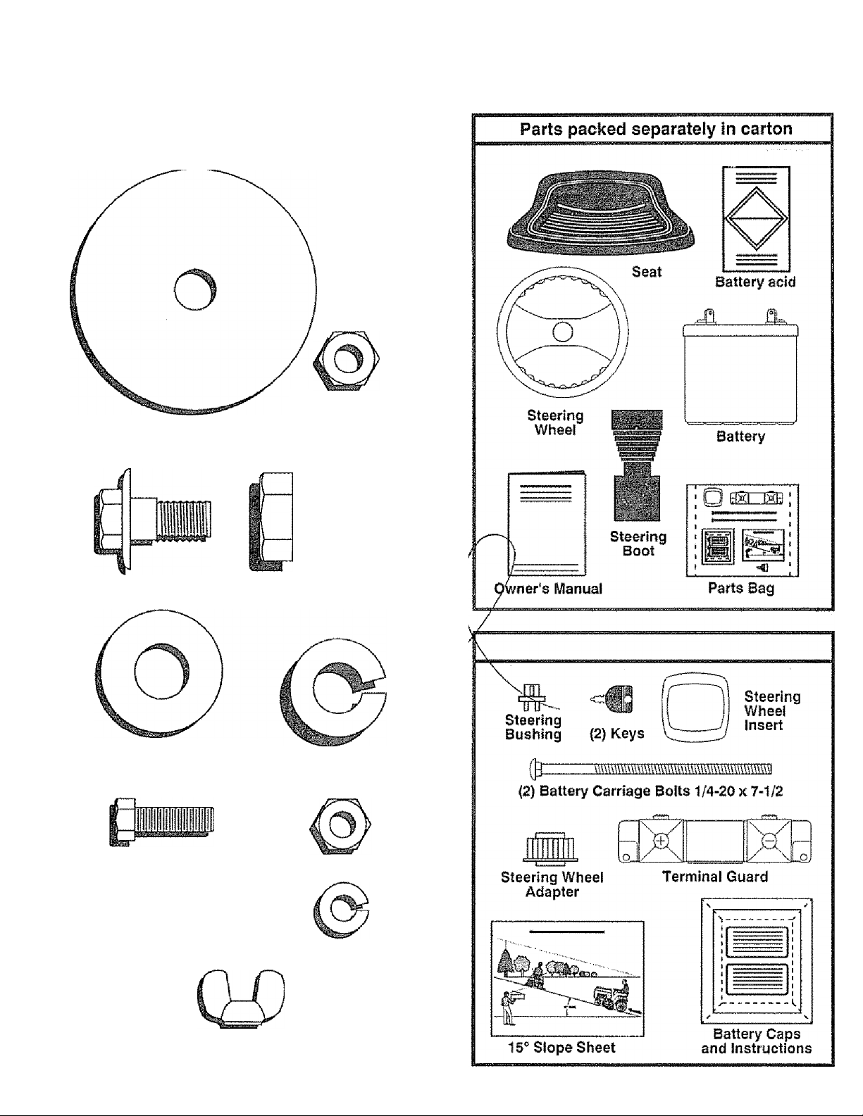
CONTENTS OF HARDWARE PACK
Parts Bag contents shown full size
(2) Sheet
Metal
Screws
#10-16x1/2
(1) Locknut 1/2*20
(1) 2-1/4" Dia, Washer
(1) Shoulder Bolt 5/16-18 (1) Hex Bolt
1/2-13x1
{1) Wsshsf
17/32 X 1 -3/16 X12 Ga {1) Lockwasher 1 /2
(2) Hex Bolts 1/4-20x3/4
(2) Washers 9/32 x5/8x 16 Ga. (2) Lock Washers 1/4
(2) Hex Nuts 1/4*20
^2) Wing Nuts 1/4-20
Page 7
ASSEMBLY
TOOLS REQUIRED FOR ASSEMBLY
A socket wrench set wili make assembly easier Standard
wrench sizes are listed.
(1) 6/16" wrench
(2) 7/1B" wrenches
(1) 1/2" wrench
(1) 9/16" wrench
When right and left hand is mentioned in this manual, it
means when you are in the operating position (seated be
hind the steering wheel|.
TO REMOVE UNIT FROM CARTON
UNPACK CARTON
• Remove all loose parts from carton (See page 6)
• Cut, from top to bottom, all four corners of carton and
lay panels flat.
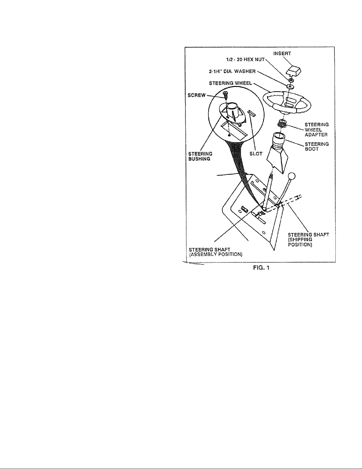
ATTACH STEERING WHEEL (See Fig. 1)
Slide the steering bushing over the steering shaft
Raise steering shaft forward until screw holes in dafeh
line up with steering bushing. Instail two (2) shd[et
metal screws and tighten securely
Position steering boot over steering shaft
Place tabs of steering boot over slots in dash and pusH
down to secure
Slide steering wheel adapter onto upper steering shaft.
Position front wheels of the tractor so they are pointing
straight forward
Position steering wheel so cross bars are horizontal/
(left to right) ana stide onto adapter
Assemble targe flat washer and 1/2-20 hex nut and
tighten securely i
Snap insert into center of steering wheel
Remove protective plastic from tractor hood
(1) 3/4" wrench
Tire pressure gauge
Screwdriver
Utility knife
BEFORE ROLLING UNIT OFF SKID
(See Fig. 6)
IMPORTANT: CHECK FOR AND REMOVE ANY
STAPLES IN SKID THAT MAY PUNC
TURE TIRES WHERE UNIT IS TO ROLL
OFF SKID.
• Raise attachment lift lever to Its highest position-
• Release parking brake by depressing clutch/brake
pedal
' Roil unit backwards off skid
Page 8
ASSEMBLY
HOW TO SET UP YOUR TRACTOR
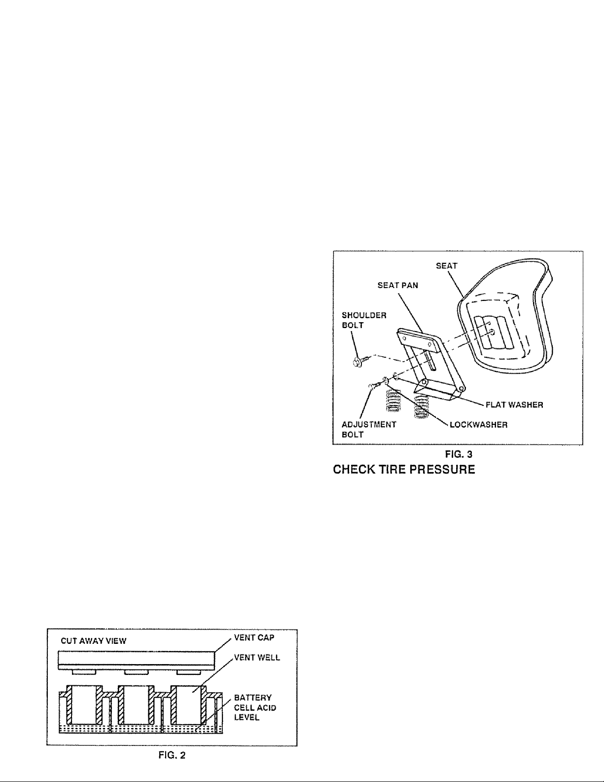
PREPARE BATTERY (See Fig. 2)
CAUTION: Wear eye and face shield.
Wash hands or clothing Immediately if
accidentally in contact with battery acid.
Do not smoke. Fumes from charged
A
Your unit has a battery charging system which is sufficient
for normal use. However, periodic charging of the battery
with an automotive charger will extend its life
• See instructions packed with vent caps in parts bag.
• Fill battery with acid. Fill each ceil until it reaches the
bottom of the vent wells Do not overfill
• Allow battery to stand and settle for at least thirty
minutes. After standing, check the level of acid. If
below the vent wells, add more acid until the correct
level is reached.
While battery is standing (after adding acid) and later, while
battery is being charged, continue with assembly of unit
• To maximize the life of your battery, it is necessary that
the battery be charged before use Use a 12 voit battery
charger. Charge battery at a rate of 6 amperes for 1
hour. Observe all safety precautions required for bat
tery charging. Failure to charge battery can result in a
shortened battery life,
• Check the add level after the battery is charged. If the
acid has fallen below the correct level, add distilled or
iron free water
• Install the vent caps to cover the vent wells, Wash the
top of the battery with water to remove any acid, then
wipe dry.
' Check battery case for leakage to make sure that no
damage has occurred in handling
• Disposeofexcessbatiery acid- Neutralize acid for dis
posal by adding it to four inches of water in a five gallon
plastic container. Stir with a wooden or plastic paddle
while adding baking soda until the addition of more
soda causes no more foaming,
• Follow instructions on how to install battery.
battery acid are explosive.
Read the instructions included with the
battery vent caps. Always wear gloves,
clothing and goggles to protect your
hands, skin and eyes.
INSTALL SEAT (See Fig. 3)
Adjust seat before tightening adjustment bolt
Remove cardboard packing on seat pan.
Place seat on pan and assemble shoulder bolt
Assemble adjustment bolt, lockwasher and flat washer
loosely. Do not tighten.
Tighten shoulder bolt securely.
Lower seat into operating position and sit on seat
Slide seat until a comfortable position is reached
which allows you to press clutch/brake pedal a“ '
way down (See Fig. 6).
Get off seal without moving Its adjusted position
Raise seat and tighten adjustment bolt securely.
The tires on your unit were overinflated at the factory for
shipping purposes. Correct tire pressure is important for
best cutting performance.
» Reduce tire pressure to PSI shown in "PRODUCT
SPECIFICATIONS“ on page 3 of this manual.
the
CHECK DECK LEVELNESS
For best cutting results, mower housing should be properly
leveled. See "TO LEVEL MOWER HOUSING" In the
Service and Adjustments section of this manual
CHECK FOR PROPER POSITION OF ALL
^3 El
See the figures that are shown for replacing motion and
mower blade drive belts in the Service and Adjustments
section of this manual. Verify that the belts are routed
correctly.
CHECK BRAKE SYSTEM
After you learn how to operate your tractor, check to see
that the brake is properly adjusted. See "TO ADJUST
BRAKE" in the Service and Adjustments section of this
manual.
8
Page 9
ASSEMBLY
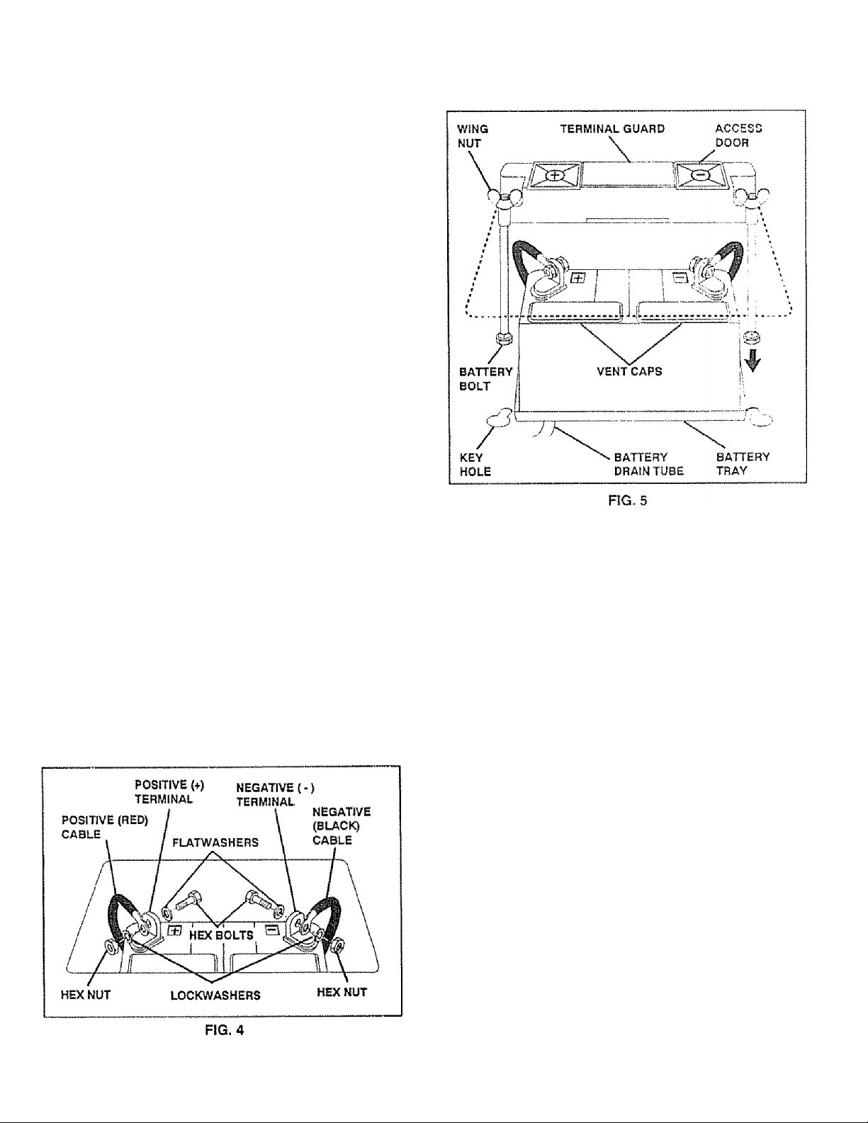
INSTALL BATTERY (See Figs. 4 & 5)
CAUTION: Do not short battery termi
nals. Before Installing battery, remove
metal bracelets, wristwatch bands,
rings, etc.
A
Positive terminal must be connected
first to prevent sparking from acciden
tal grounding,
• Lift seat to raised position
• Lower battery into fender well with battery terminals
toward front of unit. Make sure battery rests in battery
tray
• Be sure battery drain tube has not come loose and is
securely attached to drain in battery tray
• First connect RED battery cable to positive {+} battery
terminal with hex bolt, fiat washer, iockwasher and hex
nut as shown Tighten securely
• Connect BLACK grounding cable to negative {-) bat
tery terminal with remaining hex bolt, flat washer, lockwasher and hex nut Tighten securely
• Slide the two battery bolts through the terminal guard^
and start the wing nuts onto the threads '
• Position terminal guard over the battery as shownl
lower bolts into key holes and slide square shafts o|
bolts Into slots of key holes,
• Tighten wing nuts by hand making sure battery bolts^
remain in slots of the key holes in the battery support.
• Be sure terminal access doors are closed.
Use terminal access doors for: j
’ Inspection for secure connections (to tighten hard
ware).
• Inspection for corrosion.
' Testing battery.
• Jumping (if required),
• Periodic charging,
/CHECKLIST
BEFORE YOU OPERATE AND ENJOY YOUR WEW
TRACTOR, WE WISH TO ASSURE THAT YOU RECEIVE
THE BEST PERFORMANCE AND SA TISFACTION FROM
THIS QUALITY PRODUCT^
PLEASE REVIEW THE FOLLOWING CHECKLIST
All assembly instructions have been completed
/
No remaining loose parts in carton
/
Battery is properly prepared and charged (Minimum
/
1 hour at 6 amps)
Seat Is adjusted comfortably and tightened securely
/
Ail tires are properly inflated- (For shipping purposes,
/
the tires were over-inflated at the factory)
Be sure mower deck is properly leveled slde-to-side/
/
front-to-rear for best cutting results (Tires must be
properly inflated tor leveling),
Check mower and drive belts. Be sure they are routed
/
properly around pulleys and inside all belt keepers
Check wiring, See that all connections are stili secure
/
and wires are properly clamped
WHILE LEARNING HOWTO USEYOUR TRACTOR. PAY
EXTRA ATTENTION TO THE FOLLOWING MPORTANT
ITEMS:
/ Engine oil is at proper level,
/ Fuel tank is filled with fresh, clean, regular unleaded
gasoline.
/ Become familiar with all controls - their location and
function. Operate them before you start the engine
/ Be sure brake system is in safe operating condition
Page 10

OPERATION
KNOW YOUR TRACTOR
READ THIS OWNER’S MANUAL AND SAFETY RULES BEFORE OPERATING YOUR TRACTOR
Compare the iilustrations with your tractor to familiarize yourself with the locations of various controls and adjustments. Save
this manual for future reference.
Sears tractors conform to the safety standards of the American National Standards Institute.
ATTACHMENT CLUTCH LEVER: Used to engage the
mower blades, or other attachments mounted to your
tractor.
LIGHT SWITCH: Turns the headlights on and off.
THROTTLE/CHOKE CONTROL: Used for starting and
controlling engine speed.
CLUTCH/BRAKE PEDAL: Used for declutching and
braking the tractor and starting the engine.
PARKING BRAKE LEVER: Locks clutch/brake pedal into
the brake position,
A CAUTIO
TO AVOlO INJURY
■ READ OWNER'S MANUAL .
■ KNOW LOCATION AND FUNCTION OF ALL CONTROLS.
• KEEP GUARDS. SAFETY SHIELDS AND SWITCHES IN FL'
• REMOVE OBJECTS THAT CAN BE THROWN BY BUD
• DO NOT MOW WHEN CHILDREN AND OTHERS ARE Al
• NEVER CARRY CHILDREN OR PASSENGERS,
• ALWAYS LOOK BEHIND MACHINE BEFORE BACKiNQ.-
• DO NOT MOW WHERE MACHINE CAN TIP OR SLIP,
• IF MACHINE STOPS GOING UPHILL STOP BUDE AND BA
• BE SURE BLADES AND ENGINE HAVE STOPPED BEFORE
OR FEET NEAR THE 8UDES.
<- REMOVE KEY WHEN LEAVING MACHINE.
..........................................
GEARSHIFT LEVER: Selects the speed and direction of
tractor,
ATTACHMENT LIFT LEVER: Used to raise, lower, and
adjust the mower deck or other attachments mounted to
your tractor.
LIFT LEVER PLUNGER: Used to release attachment lift
lever when changing its position.
IGNITION SWITCH: Used for starting and stopping the
engine, ■
SI
10
Page 11

OPERATION
The operation of any tractor can result in foreign objects thrown into the eyes, which can
result in severe eye damage. Always wear sarety glasses or eye shields while operating
your tractor or performing any adjustments or repairs We recommend wide vision safety
mask for over the spectacles or standard safety glasses, available at Sears Retail or
Catalog stores
HOW TO USE YOUR TRACTOR
TO SET PARKING BRAKE (See Fig. 7)
• Depress clutch/brake pedal into full “8RAKE" position
and hold
• Place parking brake lever in "ENGAGED' position and
release pressurefrom clutch/brake pedal Pedal should
remain In "BRAKE" position Make sure parking brake
will hold vehicle secure
STOPPING (See Fig. 7)
MOWER BLADES ■'
• Move attachment clutch lever to "DISENGAGED" po
sition
GROUND DRIVE -
• Depress clutch/brake pedal into full “BRAKE" position
• Move gearshift lever to "NEUTRAL" position
ENGINE -
• Move throttle control to “SLOW" position
• Turn ignition key to "OFF" position and remove key
Always remove key when leaving vehicle to prevent
unauthorized use
• Never use choke to stop engine
TO USE THROTTLE CONTROL (See Fig. 7)
Always operate engine at full throttle
> Operating engine at less than full throttle reduces the
battery charging rate and the engine cooling air flow
• Full throttle offers the best bagging and mower per
formance
TO MOVE FORWARD AND BACKWARD (See
Fig- 6)
The direction and speed of movement is controlled by the
gearshift lever
• Start tractor with clutch/brake pedal depressed and
gearshift lever in "NEUTRAL" position
• Move gearshift lever to desired position
• Slowly release clutch/brake pedal to start movement.
The position of the attachment lift lever determines the
cutting height
• Grasp lift lever
- Press plunger with thumb and move lever to desired
position
The cutting height range is approximately 1-1/4 to 3-3/4"
The heights are measured from the ground to the blade tip
with the engine not running These heights are approxi
mate and may vary depending upon soil conditions, height
of grass and types of grass being mowed-
• The average lawn should be cut approximately 2-1/2
inches during the coo! season and over 3 inches during
hot months For healthier and better looking lawns,
mow often and after moderate growth
• For best cutting performance, grass over 6 inches in
height should be mowed twice Make the first cut
relatively high; the second to desired height
11
Page 12

OPERATION
TO OPERATE MOWER (See Fig. 8)
Your unit is equipped with an operator presence sensing
switch. Any attempt by the operator to leave the seat with
the engine running and the attachment clutch engaged will
shut oft the engine,
• Select desired height of cut
• Engage mower by slowly moving attachment dutch
lever to “ENGAGED" position,
‘ TO STOP MOWER - Move attachment clutch lever to
"DISENGAGED" position.
CAUTION: DO NOT OPERATE THE
MOWER WITHOUT EITHER THE EN
TIRE GRASS CATCHER, ON MOWERS
A
A
SO EQUIPPED, OR THE DISCHARGE
GUARD IN PLACE.
CAUTION: DO NOT DRIVE UP OR
DOWN H! LLS WITH S LOP ES G R EATER
THAN ISLAND DONOTDRIVEACROSS
ANY SLOPE.
• if stopping is absolutely necessary, push dutch/brake
pedal quickly to brake position and engage parking
brake,
' Move gearshift lever to 1st gear and be sure you have
allowed room for tractor to roll slightly as you restart
movement
• To restart movement, slowly release par king brake and
clutch/brake pedal,
• Make ali turns slowly,
TO TRANSPORT
• Raise attachment lift control to highest position.
• When pushing or towing your unit, be sure gearshift
lever is in "NEUTRAL" position.
» Do not push or tow unit at more than five (5) MPH
BEFORE STARTING THE ENGINE
CHECK ENGINE OIL LEVEL (See Fig. 16)
• The engine in your unit has been shipped, from the
factory, already filled with summer weight oil,,
• Check engine oil with unit on level ground.
■ Remove oil fill dipstick and wipe clean, replace and
screw cap tight, wait for a few seconds, remove and
read oil level. If necessary, add oil until "FULL" mark
on dipstick is reached. Do not overfill,
• For cold weather operation you should change oil for
easier starting (see "OIL VISCOSITY CHART" in the
Maintenance section of this manual).
' To change engine oil, see the Maintenance section in
this manual.
ADD GASOLINE
• Fili fuel tank. Use fresh, clean, regular unleaded gaso
line, (Use of leaded gasoline will increase carbon and
lead oxide deposits and reduce valve life).
IMPORTANT: WHEN OPERATING IN TEMPERA
TURES BELOW32°F(0“C), USE FRESH,
CLEAN WINTER GRADE GASOLINE TO
HELP INSURE GOOD COLD WEATHER
STARTING.
WARNING: Experience indicates that alcohol biended
fuels (called gasohol or using ethanol or methanol) can
attract moisture which leads to separation and formation of
acids during storage, Acidic gas can damage the fuel
system of an engine while in storage. To avoid engine
problems, the fuel system should be emptied before stor
age of 30 days or longer. Drain the gas tank, start the
engine and let it run until the fue! lines and carburetor are
empty. Use fresh fuel next season. See Storage Instruc
tions for additional information. Never use engine or
carburetor cleaner products in the fuel tank or permanent
damage may occur.
Choose the slowest speed before starting up or down
hills.
Avoid stopping or changing speed on hills.
If slowing Is necessary, move throttle control lever to
slower position.
12
A
CAUTION: FILL TO BOTTOM OF GAS
TANK FILLER NECK. DO NOT OVER
FILL WIPE OFFANY SPILLED OIL OR
FUEL DO NOT STORE, SPILL OR USE
GASOLINE NEAR AN OPEN FLAME.
Page 13

OPERATION
TO START ENGINE (See Fig. 7)
When starting engine for the first time or if engine has
run out of fuei, it will take extra cranking time to move
fuel from the tank to the engine
' Depress the clutch/brake pedal and set the parking
brake-
• Place gearshift lever in "NEUTRAL" position.
• Move attachment clutch to "DISENGAGED" position
• Move throttle control lever to "CHOKE" position for
cold engine start For warm engine start, move
throttle contro! to "FAST" position.
• Turn ignition key clockwise to "START" position and
release key as soon as engine starts. Do not run
starter continuously for more than fifteen seconds
per minute. If engine does not start after several
attempts, move throttle control to "FAST" position,
wait a few minutes and try again
• When engine starts, move throttle control to desired
position.
• Allow engine to warm up for a few minutes before
engaging drive or attachment clutch.
NOTE: If at a high altitude (above 3000 feet) or in cold
temperatures (below 32“ F), the carburetor fuel mixture
may need to be adjusted for best engine performance.
See “TO ADJUST CARBURETOR" in the Service and
Adjustments section of this manual,
MOWING TIPS
• Tire chains cannot be used when the mower hous
ing is attached to unit
• Mower should be properly leveled for best mowing
performance. See "TO LEVEL MOWER HOUSING"
in the Service and Adjustments section of this
manual.
• Use the runner on the right hand side of mower as
a guide. The blade cuts approximately an inch
outside the runner (See Fig 8).
• The left hand side of mower should be used for trim
ming.
Drive so that clippings are discharged onto the area
that has been cut. Have the cut area to the right of
the machine. This will result in a more even distri
bution of clippings and more uniform cutting.
When mowing large areas, start by turning to the
right so that clippings wiil discharge away from
shrubs, fences, driveways, etc. After one or two
rounds, mow in the opposite direction making left
hand turns until finished (See Fig, 9).
If grass is extremely tall, it should be mowed twice
to reduce load and possible fire hazard from dried
clippings. Make first cut relatively high; the second
to the desired height '
Do not mow grass when it is wet. Wet grass wiil
piug mower and leave undesirable dumps Allow
grass to dry before mowing
Always operate engine at lull throttle when mowing
to assure better mowing performance and proper
discharge of material. Regulate ground speed by
selecting a low enough gear to give the mower
cutting performance as well as the quality of cut
desired.
When operating attachments, select a ground speed
that will suit the terrain and give best performance of
the attachment being used.
13
Page 14

MAINTENANCE
MAINTENANCE SCHEDULE
FILL iN DATES
AS YOU COMPLETE
REGULAR SERVICE
Check Brake Operation | ^
Check Tire Pressure
Chsck fof Loose Fasteners
Sharpen/Replace Mower Blades
Lubrication Chart
Check Battery Level/Recharge
Clean Battery and Terminals
Check Trarrsmlsslon Cooling
Adjust Blade Beit(s) Tension
Adjust Motion Drive Ba!t(s) Tension
iM
✓
4
|/
|/
|/
. .
Check Engine 01! Levei
Change Engine Oil
Clean Air Filter
Clean Ail Screen
Inspect MuffleVSpark Arrester
Replace Oil Filter (If equipped)
Clean Engine Cooling Firrs
Replace Spark Plug
Replace Air Filter Paper Cartridge
Replace Fuel Filter
1 - Change more often whan oparailng under a haavy load or In high ambient tetnperaturag, 3 - If equipped with oil filisr, change oil every SO hours
2 - Service more often when oparating in dirty or dusty condltJans 4 - Replace blades mare oflert when mowing in sandy soil,
GENERAL RECOMMENDATIONS
The warranty on this vehicle does not cover items that have
been subjected to operator abuse or negligence, To
receive full value from the warranty, operator must main
tain unit as instructed in this manual
Some adjustments wl!l need to be made periodically to
properly maintain your unit
All adjustments in the Service and Adjustments section of
this manual should be checked at least once each season.
• Once a year you should replace the spark plug, ciean
or replace air filter, and check blades and belts for
wear. A new spark plug and dean air filter assure
proper air-fuel mixture and help your engine run better
and last longer.
t/
1^2.3
2
l/"2
\ I
y
^2
/\
|/
-^2
%/
t
1
✓
LUBRICATION CHART
(D SPINDLE ZERK
(If equipped)
fS) FRONT WHEEL'
^BEARING 2ERK
0 ATTACHMENT
CLUTCH PIVOT
SPINDLE ZERK@
(If equipped)
FRONT WHEEL®
BEARING ZERK
ENGINE®
BEFORE EACH USE
• Check engine oil level,
• Check brake operation.
• Check tire pressure.
• Check for loose fasteners.
® SAE 30 OR 10W30 MOTOR OIL API - SF/CC
® GENERAL PURPOSE GREASE
® REFER TO ENGINE MAINTENANCE SECTION
IMPORTANT: DO NOT OIL OR GREASE THE PIVOT POINTS
WHICH HAVE SPECIAL NYLON BEARINGS VISCOUS LUBRI
CANTS WILL ATTRACT OUST AND DIRT THAT WILL SHORTEN
THE LIFE OF THE SELF-LUBRICATING BEARINGS, IF YOU
FEEL THEY MUST BE LUBRICATED, USE ONLY A DRY, POW
14
DERED GRAPHITE TYPE LUBRICANT SPARINGLY,
Page 15

MAINTENANCE
TRACTOR
Always observe safety rules when performing any mainte*
nance.
TIRES
• Maintain proper air pressure in all tires (See "PROD
UCT SPECIFICATIONS" on page 3 of this manual).
• Keep tires free of gasoline, oil, or insect control chemi
cals which can harm rubber
• Avoid stumps, stones, deep ruts, sharp objects and
other hazards that may cause tire damage.
BLADE CARE
For best results mower blades must be kept sharp The
blades can be sharpened with a file or on a grinding wheel.
We suggest they be sharpened or replaced after every 25
hours of mowing Check blades more often if mowing in
sandy conditions
• Do not attempt to sharpen blades while they are on the
mower.
• Replace bent or damaged blades
BLADE REMOVAL (See Fig. 10)
• Raise mower to highest position to allow access to
blades,
• Remove hex bolt, lockwasherand flat washer securing
blade.
• Install new or resharpened blade with trailing edge up
towards deck as shown.
• Reassemble hex bolt, locNwasher and flat washer in
exact order as shown.
• Tighten bolt securely (30-35 Ft. Lbs. torque).
IMPORTANT; BLADE BOLT IS GRADE 5 HEATTREATEO.
TO SHARPEN BLADE (See Fig. 11)
Care should be taken to keep the blade balanced. An
unbalanced blade will cause excessive vibration and even
tual damage to mower and engine,
• The blade can be sharpened with a file or on a grinding
wheel Do not attempt to sharpen while on the mower
• Tocheck blade balance, drive a nail into a beam or wall
Leave about one inch of the straight nail exposed.
Place center hole of blade over the head of the nail If
blade is balanced, it should remain in a horizontal
position. If either end of the blade moves downward,
sharpen the heavy end until the blade is balanced
CENTER
HOLE
.
....
—-.
1
III
l| Щ
о "">0 c
1ЛМ1
FIG, 11
BLADE
u
15
Page 16

MAINTENANCE
BATTERY (See Fig. 12)
Your unit has a battery charging system which is sufficient
for normal use. However, periodic charging of the battery
with an automotive charger will extend it's iife.
• Acid solution level in each battery cell should be even
with bottoms of vent wells. Add only distilled or iron free
water If necessary. Do not overfill.
• Keep battery and terminals clean.
• Keep battery bolts tight
• Keep vent caps tight and small vent holes in caps open.
• Recharge at 6 amperes for 1 hour.
TO GLEAN BATTERY AND TERMINALS -
Corrosion and dirt on the battery and termirrais can cause
the battery to “leak" power.
• Remove terminal guard.
• Disconnect BLACK battery cable first then RED bat
tery cable and remove battery from tractor.
■ Wash battery with solution of four tablespoons of bak
ing soda to one gallon of water. Be careful not to get
the soda solution into the cells.
‘ Rinse the battery with plain water and dry.
• Clean terminals and battery cable ends with wire brush
until bright
• Coat terminals with grease or petroleum jelly.
• Reinstall battery (See “INSTALL BATTERY' in as
sembly section of this manual).
Catch oil in a suitable container.
Remove oil fill dipstick. Be careful not to allow dirt to
enter the engine when changing oil.
Remove drain plug.
After oil has drained completely, replace oil drain plug
and tighten securely.
Refill engine with oil through oil fill dipstick tube. Pour
slowly, Do not overfill. For approximate capacity see
Product Specifications on page 3 of this manual.
Use gauge on oil fill dipstick for checking level. Be sure
dipstick cap is tightened securely for accurate reading.
Keep oH at "FULL" line on dipstick.
AIR FILTER (See Fig. 14)
ENGINE
LUBRICATION
Change the oil after the first two hours of operation and
every 25 hours thereafter or at least once a year if the
tractor is not used for 25 hours in one year.
Check the crankcase oil level before starting the engine
and after each eight (8) hours of continuous use. Add SAE
SOW motor oil or equalivent Tighten oil fllj cap/dipstick
securely each time you check the oil level. SAE 5W-30
motor oil may be used to make starting easier in areas
where temperature is consistently 32” F or lower.
TO CHANGE ENGINE OIL (See Fig. 13)
Determine temperature range expected before oil change.
All oil must meet API service classification SD, SE or SF.
• Be sure vehicle is on levei surface.
• Oil will drain more freely when warm.
Your engine will not run property and may be damaged by
using a dirty air filter. Replace paper cartridge once a year
or after every 100 hours of operation, more often if used in
very dusty, dirty conditions.
• Remove knobs and cover.
• Remove cartridge nut and replace cartridge.
• Reassemble and tighten securely.
NOTE: Do not attempt to clean or oil the paper cartridge.
16
Page 17

MAINTENANCE
AIR SCREEN (See Fig. 13)
The engine air screen must be kept free of dirt and chaff to
prevent engine damage from overheating. Clean with a
wire brush or compressed air to remove dirt and stubborn
dried gum fibers.
MUFFLER
inspect and replace corroded muffierand spark arrester (if
equipped) as it could create afire hazard and/or damage
SPARK PLUGS
Replace spark plugs at the beginning of each mowing
season or after every 100 hours of use, whichever comes
first. Spark plug type and gap setting is shown in "PROD
UCT SPECIFICATIONS" on page 3 of this manual,
IN-LINE FUEL FILTER (See Fig. 16)
Fuelfiltershould be replaced once each season, iffuelfilter
becomes clogged, obstructing fuel flow to carburetor, re
placement is required.
• With engine cool, remove filter and plug fuel line
sections,
, Place new fuel filter in position in fuel line,
• Be sure there are no fuel line leaks and clamps are
properly positioned.
• Immediately wipe up any spilled gasoline.
ENGINE COOLING FINS (See Fig, 15)
Remove any dust, dirt or oil from engine cooling fins to
prevent engine damage from overheating.
• Remove oil fill dipstick and cover opening to prevent
entry of dirt.
• Remove screws from blower housing and lift housing
off engine.
. Remove the screws securing the starter housing and
iift housing off engine.
• Use compressed air or stiff bristle brush to thoroughly
clean engine cooling fins,
• To reassemble, reverse above procedure.
FiG. 16
CLEANING
» Clean engine, battery, seat, finish, etc. of all foreign
matter,
* Keep finished surfaces and wheels free of all gasoline,
oil, etc.
• Protect painted surfaces with automotive type waxWe do not recommend using a garden hose to clean your
uni! unless the electrical system, muffler, air filter and car
buretor are covered to keep water out. Water in engine can
result in a shortened engine iife.
17
Page 18

A
SERVICE AND ADJUSTMENTS
CAUTION: BEFORE PERFORMING ANY SERVICE OR ADJUSTMENTS:
■ Depress clutch/brake pedal fully and set parking brake.
• Place gearshift lever in "NEUTRAt," position.
• Place attachment clutch in "DISENGAGED" position.
• Turn ignition key “OFF" and remove key.
• Make sure the blades and all moving parts have completely stopped.
• Disconnect spark plug vi/ire from spark plug and place wire where it cannot come in contact with
plug.
TD ACTACS
I iiMW I wis
TO REMOVE MOWER (See Ftg. 17)
Mower will be easier to remove from the right side of unit
- Remove mower blade drive belt from engine pulley
only (b66 tU HerLAOiI MUVVcH dLAUC UnlVil
BELT" through step removing belt from engine pulley)
• Remove retainer spring from dutch rod; pull dutch rod
out of clutch lever,
• Puli retainer springs out of rear suspension trunnions,
Remove rear suspension trunnions from lift brackets,
• Pull retainer springs from front hinge pins,
• Remove hinge pins attaching parallel link to mower
and front axle,
• Raise lift lever to raise suspension arms Slide mower
out from under tractor.
IMPORTANT: IF AN ATTACHMENT OTHERTHANTHE
MOWER IS TO BE MOUNTED TO THE
TRACTOR. THE R.H. AND LH. SUS
PENSION ARMS MUST BE REMOVED
FROM TRACTOR.
TO INSTALL MOWER (See Fig. 17)
' Raise attachment lift lever to its highest position.
* Slide mower under tractor with dischar ge guard to right
side of tractor
• Install parallel link to front axle and mower with hinge
pins. Secure hinge pins with retainer springs.
' Install clutch rod in clutch lever and secure with retainer
spring.
♦ Lower attachment lift lever to lower suspension arms,
Slide trunnions through lift bracket holes and secure
with retainer springs,
* Roll belt over engine pulley. Make sure belt is Inside all
pulley grooves and inside belt guides.
• Raise attachment lift lever to raise mower,
TO LEVEL MOWER HOUSING
Adjustthe mower while tractor is parked on level ground or
driveway. Make sure tires are properly inflated (See
‘>DDnni ir»T QDCrr'JCrir'ATIAMQ*^ nn пало tlrott iiro
r nUUUw I or CwlrloM i IwlNv^ on рЗув i( luSS аГв
over or under inflated, you will not properly adjust your
mower
SIDE-TO-SIDE ADJUSTMENT (See Figs.18 and19) -
Raise attachment lift lever to Its highest position.
Measure height from bottom of deck curl to ground
level at front corners of mower. Distance "A" should be
the same.
If distance "A" needs to be changed, snap out access
hole cover on left side of tractor above footrest
To raise ¡eft side of mower, loosen nut "B" and tighten
nut "C".
T0 lower left side of mower, loosen nut "C and tighten
nut *B".
When distance
and "C",
Replace access hole cover.
A" is equal, securely tighten nuts "B"
18
Page 19

UFT LEVER
(RAISED
POSITION) ~
SERVICE AND ADJUSTMENTS
BOTTOM
OF CURL
BOTTOM
OF CURL
GROUND LINE
FIG. 19
FRONT-TO-BACK ADJUSTMENT(See Figs. 20 and 21) -
To obtain the best cutting results, the mower housing
should be adjusted so the rear is approximately 3/4 to 7/8"
higher than the front when the mower is in its highest
position.
Check adjustment on right side of tractor. Measure dis
tance “D" at front and rear flanges of mower housing as
shown.
' To raise rear of mower, loosen nut "E” on both rear
suspension arms. Screw both nuts "F" on both rear
suspension arms an equal number of turns.
' When distance "D" is 3/4 to 7/8" higher at rear than
front, retighten nuts "E".
• Recheck side-to-side adjustment.
IMPORTAMT: WHEN ADJUSTING REAR SUSPENSION
TRUNNIONS, ALWAYS ADJUST BOTH EQUALLY SO
MOWER WILL STAY LEVEL SIDE-TO-SIDE,
19
Page 20

SERVICE AND ADJUSTMENTS
TO ADJUST MOWER BLADE DRIVE BELT
(See Fig. 22)
Your tractor has been manufactured with the ability to
readjust the mower blade drive belt to provide you with
longer belt life
With the engine off and the lift lever in the highest po
sition, move clutch lever up slowly until resistance is felt.
If distance from bottom of slot in dash to clutch lever is
greater than 4-1/2 inches, adjustment is necessary,
• Lower the mower deck for easier access.
• Remove the boll, nut and D-shaped washers from
rock shaft assembly.
' Move extension spring from iower to upper end of
slot in rock shaft assembly and install boit, nut and
the D-shaped washers (flat side of washers down),
• Tighten bolt and nut to secure the D-shaped wash
ers (flat side down as shown),
TO REPLACE MOWER BLADE DRIVE BELT
(See Figs. 22 and 23)
The mower blade drive belt may be replaced without
tools Park the tractor on level surface Engage parking
brake. For assistance, there is a belt installation guide
decal on the mower housing.
BELT REMOVAL -
Place attachment dutch In "DISENGAGED" position.
Move attachment lift lever forward to iower mower to
its iowest position
Roil belt off engine puHey.
Pull belt off both mandrel pulleys.
Spring belt guide away from idler pulley and puli belt
orf idler pulley
Slide belt from under extension spring.
BELT INSTALLATION -
Slide belt under extension spring.
Place belt around back side and in groove of both
mandrel pulleys.
Spring idler belt guide down and place belt around
rear side of idler pulley
Roll belt over engine pulley
Make sure belt is in ail pulley grooves and inside all
belt guides
20
Page 21

SERVICE AND ADJUSTMENTS
TO ADJUST BRAKE (See Fig. 24)
Your unit is equipped with an adjustable brake system
which is mounted on the right side of the transaxle,
if unit requires more than six (6) feet stopping distance at
high speed in highest gear, then brake must be adjusted
• Depress clutch/brake pedal and engage parking brake
• Measure distance between brake operating arm and
nut “A" on brake rod.
• If distance is other than 1-1/2*', disengage parking
brake, loosen jam nut and turn nut "A" until distance
becomes 1-1/2". Retighten jam nut against nut "A",
• Engage parking brake and recheck distance,
• Road test unit for proper stopping distance as stated
above. Readjust if necessary, if stopping distance is
still greater than six (6) feet in highest gear, further
maintenance is necessary. Contact your nearest
Sears Service Center.
WÍTH PARKING BRAKE "ENGAGED“
TO REPLACE MOTION DRIVE BELT (See
ig. 25)
The tractor drive belt may be replaced without tools.
Park the tractor on level area. Engage parking brake.
For assistance, there is a belt installation guide decal on
bottom side of left footrest-
• Remove mower (See "TO REMOVE MOWER" In this
section of this manual).
• Roll belt over top of transaxie pulley.
• Roll belt over engine pulley and off idler.
• Release parking brake. Pull belt as far as possible
over top of clutch pulley.
• Reset parking brake. Puli belt over top of clutch
pulley
• Pull belt out up through gearshift lever gate opening
to remove from tractor.
• Install new belt by reversing above procedure
replace only with belt listed in
THIS MANUAL.
FIG. 24
FIG. 25
21
Page 22

SERVICE AND ADJUSTMENTS
TO ADJUST STEERING WHEEL ALIGNMENT
!f steering wheel crossbars are not horizontal (left to right)
when wheels are positioned straight forward, remove
steering wheel and reassemble per instructions in the
Assembly section of this manual.
FRONT WHEEL TOE-IN/CAMBER
The front wheel toe-in and camber are not adjustable on
your unit. If damage has occured to affect the front wheel
toe-in or camber, contact your nearest Sears Service
Center,
TO REMOVE WHEEL FOR REPAIRS (See
Fig. 26)
• Block up axie securely.
• Remove hub cap. retaining ring and washers to allow
wheel removal (rear wheel contains a square key - Do
not lose),
' Repair tire and reassemble.
• On rear wheels only: align grooves in rear wheel hub
and axle, Insert square key.
- Replace washers and snap retaining ring securely in
axle groove.
• Replace hub cap.
TO START ENGINE WITH A WEAK BATTERY
(See Figs. 27 & 28)
CAUTION: Lead-add batteries gener
ate explosive gases. Keep sparks, flame
«•■ivi- ^ smoking materials away from bat
teries. Always wear eye protection
“■ ' when around batteries.
If your battery is too weak to start the engine, it should be
recharged. If "jumper cables“ are used for emergency
starting, follow this procedure:
IMPORTANT: YOUR UNIT iS EQUIPPED WITH A 12
VOLT NEGATIVE GROUNDED SYSTEM. THE OTHER
VEHICLE MUST ALSO BE A 12 VOLT NEGATIVE
GROUNDED SYSTEM. DO NOT USE YOUR TRACTOR
BATTERY TO START OTHER VEHICLES.
TO ATTACH JUMPER CABLES -
• Connect each end of the RED cable to the POSITIVE
(+) terminal of each battery, taking care not to short
against chassis.
• Connect one end of the BLACK cable to the NEGA
TIVE (-) terminal of fully charged battery.
• Connect the other end of the BLACK cable to a panel
bolt on the left side of the chassis, away from fuel tank
and battery,
TO REMOVE CABLES, REVERSE ORDER -
• BLACK cable first from left side of chassis and fully
charged battery,
• RED cable last from both batteries.
22
Page 23

SERVICE AND ADJUSTMENTS
TO REPLACE FUSE (See Fig. 29)
Replace with 30 amp automotive-type plug-in fuse. The
fuse holder is located in the engine compartment, directly
in front of the dash.
TO REPLACE HEADLIGHT BULB
• Raise hood.
• Pull bulb holder out of the hole in the backside of the
grill.
• Replace bulb in holder and push bulb holder securely
back into the hole in the backside of the grill
• Close hood.
INTERLOCKS AND RELAYS
Loose or damaged wiring may cause your tractor to run
poorly, stop running or prevent it from starting.
• Check wiring. See eiectrical wiring diagram in Repair
Parts section of this manual,
TO REMOVE HOOD, GRILL AND SIDE PAN
ELS (See Fig's. 30 and 31)
• Raise hood.
• Unsnap headlight wire connector,
• Stand at side of tractor. Grasp hood and tilt forward
and lift off hinge brackets.
- To re install,slide hood pivot rod Into slot in hinge
brackets, and carefully reinstall hood springs.
•
23
Page 24

SERVICE AND ADJUSTMENTS
ENGINE
TO ADJUST THROTTLE CONTROL CABLE
(See Fig. 32)
The throttle control has been preset at the factory and ad
justment should not be necessary. Check adjustment as
described below before loosening cable if adjustment is
necessary, proceed as follows:
* With engine not running, move throttle control lever
from "SLOW" to "CHOKE" position Slowly move lever
from "CHOKE" to "FAST" position
• Check that hoies "A" in governor control lever and hoie
in governor plate line-up. If holes "A" are not aligned,
loosen clamp screw and move throttle cable until holes
are aligned. Tighten damp screw securely.
FIG. 32
FINAL SETTING -
• Start engine and allow to warm for five minutes. Make
final adjustments with engine running and shift/motlon
control lever in “NEUTRAL" position,
• Move throttie control lever to "SLOW" position. With
finger, rotate and hold throttle lever against idle speed
screw. Turn idle speed screw to attain 1750 RPM.
• While still holding throttle lever against idle speed
screw, turn idle mixture valve in (clockwise) until en
gine begins to die and then turn out (counterclockwise)
until engine runs rough. Turn valve to a point midway
between those two positions, Release throttle lever.
ACCELERATION TEST -
• Move throttle control lever from "SLOW" to "FAST"
position. If engine hesitates or dies, turn Idle mixture
valve out (counterclockwise) 1/8 turn, Repeattestand
continue to adjust, if necessary, until engine acceler
ates smoothly.
High speed stop Is factory adjusted. Do not adjust -
damage may result.
IMPORTANT: NEVER TAMPER WITH THE ENGINE
GOVERNOR, WHICH tS FACTORY SET
FOR PROPER ENGINE SPEED. OVER
SPEEDING THE ENGINE ABOVE THE
FACTORY HIGH SPEED SETTING CAN
BE DANGEROUS, IF YOU THINK THE
ENGINE-GOVERNED HIGH SPEED
NEEDS ADJUSTING, CONTACT YOUR
NEAREST AUTHORIZED SERVICE
CENTER, WHICH HAS PROPER EQUIP
MENT AND EXPERIENCETOMAKEANY
A DV AH H ICTfulCMTC!
«HLJvww I IVitZiN I
TO ADJUST CARBURETOR (See Fig. 33;
The carburetor has been preset at the factory and adjust
ment should not be necessary. However, minor adjust
ment may be required to compensate for differences in fuel,
temperature, altitude or load. If the carburetor does need
adjustment, proceed as follows:
In general, turnig idle mixture valve in (clockwise) de
creases the supply of fuel to the engine giving a leanerfuel/
air mixture, Turning the idle mixture valve out (counter
clockwise) increases the supply of fuel to the engine givirig
a richer fuei/air mixture.
IMPORTANT: DÁMAGETOTHENEEDLEVALVE AND
THE SEAT IN CARBURETOR MAY RE
SULT IF SCREW IS TURNED IN TOO
TIGHT,
PRELIMINARY SETTING♦ Air cleaner assembly must be assembled to the carbu
retor when making carburetor adjustments,
« Be sure the throttle control cable is adjusted properly
(see above),
' With engine off turn idle mixture valve in (clockwise)
closing it finger tight and then turn out (counterciockwise) 1 full turn.
Page 25

STORAGE
Immediately prepare your tractor for storage at the end of
the season or if the unit will not be used for 30 days or more.
CAUTION: Never* store the tractor with
gasoline in the tank inside a buliding
where fumes may reach an open flame
or spark. Allow the engine to cool
before storing in any enclosure.
TRACTOR
Remove mower from tractor for winter storage. When
mower is to be stored for a period of time, clean it thor
oughly, remove ail dirt,^ grease, leaves, etc. Give biades
and underside of housing a good coat of grease or rust
preventative. Store in a clean, dry area,
" Clean entire tractor {See “CLEANING" in the Mainte
nance section of this manual).
• Inspect and replace belts, if necessary (See belt re
placement Instructions in the Service and Adjustments
section of this manual).
• Lubricate as shown in the Maintenance section of this
manual.
■ Be sure that all nuts, bolts and screws are securely
fastened. Inspect moving parts for damage, breakage
and wear. Replace if necessary.
■ Touch up all rusted or chipped paint surfaces; sand
lightly before painting.
— A'i"T p DY
f 1 Im li 1
• Fully charge the battery for storage,
• After a period of time In storage, battery may require
recharging,
• To help prevent corrosion and power leakage during
long periods of storage, battery cables should be
disconnected and battery cleaned thoroughly (see "TO
CLEAN BATTERY AND TERMINALS" in the Mainte
nance section of this manual).
• After cleaning, leave cables disconnected and place
cables where they cannot come in contact with battery
terminals,
• Be sure battery drain tube is securely attached to drain
in battery tray.
• Drain the fuel tank.
• Start the engine and let it run until the fuel lines and
carburetor are empty.
• Never use engine or carburetor cleaner products in the
fuel tank or permanent damage may occur,
• Use fresh fuel next season.
NOTE: Fuel stabilizer is an acceptable alternative in mini
mizing the formation of fuel gum deposits during storage.
Add stabilizer to gasoline in fuel tank or storage container.
Always follow the mix ratio found on stabilizer container.
Run engine at least 10 minutes after adding stabilizer to
allow the stabilizer to reach the carburetor. Do not drain the
gas tank and carburetor if using fuel stabilizer.
ENGINE OIL
Drain oil (with engine warm) and replace with clean engine
oil. (See “ENGINE" in the Maintenance section of this
manual).
CYLINDERS
, pernove spark piug(s).
• Pour one ounce of oil through spark plug hole(s) into
cylinder.
• Turn ignition key to “START’ position for afew seconds
to distribute oil
• Replace with new spark plug(s).
OTHER
' Do not store gasoline from one season to another,
• Replace your gasoline can if your can starts to rust
Rust and/or dirt in your gasoline will cause problems,
• If possible, store your unit indoors and cover it to give
protection from dust and dirt,
• Cover your unit with a suitable protective cover that
does not retain moisture. Do not use plastic. Plastic
cannot breathe which allows condensation to form and
will cause your unit to rust.
IMPORTANT: NEVER COVER TRACTOR WHILE
ENGINE AND EXHAUST AREAS ARE STILL WARM
ENGINE
FUEL SYSTEM
IMPORTANT: IT !S IMPORTANT TO PREVENT GUM
DEPOSITS FROM FORMING IN ESSENTIAL FUEL
SYSTEM PARTS SUCH AS CARBURETOR, FUEL FILTER.
FUEL HOSE. OR TANK DURING STORAGE, ALSO,
EXPERI ENCE INDICATES THAT ALCOHOL BLENDED
FUELS (CALLED GASOHOL OR USING ETHANOL OR
METHANOL) CAN ATTRACT MOISTURE WHICH LEADS
TO SEPARATION AND FORMATION OF ACIDS DURING
STORAGE ACIDIC GAS GAN DAMAGE THE FUEL
SYSTEM OF AN ENGINE WHILE IN STORAGE
25
Page 26

TROUBLESHOOTING POINTS
PROBLEM
Will not start
Hard to start
Engine will not turn over
Engine clicks but will not
start
CAUSE
Out of fuel,
1.
Engine not “CHOKED" properly.
2.
Engine flooded. 3,
3
4 Sad spark plug.
Dirty a)r filter.
5,
Dirty fuel filter.
6.
7. Water In fuel
Loose or damaged wiring. a.
8.
1 9 Carburetor Out of ad|ustment.
Engine valves out of adjustment
1 10.
Dirty air filter.
1 2 Bad spark plug.
3. Weak or dead battery.
4. Dirty fuel filler.
5. Stale or dirty fuel.
Loose Of damaged wiring.
6,
7 Carburetor out of adjustment.
Engine valves out of adjustment 8.
a.
1. Clutcb/brake pedal not depressed,
2. Attachment dutch Is engaged.
3„ Spark plug wire Is disconnected. 3.
Weak Of dead battery. 4.
4,
5. Blown fuse.
6. Corroded battery terminals.
Loose or damaged wiring. 7, Check all wiring.
7„
Faulty Igrrltloft switch.
8-
9,
Faulty solsrroid or starter 9.
10. Faulty operator presence swltoh(es).
1 Weak Of dead battery.
2. Corroded battery terminals. 2. Glean battery terminals.
3. Loose Of damaged wiring. 3.
Faulty solenoid or starter.
4.
.......\
..............
.....\.........
CORRECTION
Fill fuel tank
1.
2, See TO START ENGINE In operation section.
Wait several minutes before aftempling to start.
Replace spark plug.
4.
5. Glean/replace air filter.
Replace fuel filter.
6.
Drain fuel lank and carburetor, refill tank with fresh
7-
gasoline and replace fuel filter.
Check all wiring.
Contact Seats Service Department.
9,
Contact Sears Service Department,
10.
Clean/replace air filter.
1.
2. Replace spark plug
Recharge or replace battery.
3.
Replace fuel filter.
4.
Drain fuel tank and refill with fresh gasoline.
6.
Check all wiring.
6.
Contact Sears Service Department.
7.
Contact Sears Service Department,
Depress Clutch/brake pedal.
1.
2. Disengage attachment clutch.
Connect wire to spark plug.
Recharge or replace battery.
5. Replace fuse.
6. Glean battery terminals.
Check/replace ignition switch.
8.
Check/replace solenoid or starter,
Contact Sears Service Department.
10.
1. Recharge or replace battery,
Check all wiring. -
Check/replace solenoid or starter.
4.
Loss of power
Excessive vibration
1. Cutting too much grass/too fast.
2. Throttle In "CHOKE" position.
Buitd-up of grass, leaves and trash under mower.3.
3.
4.
Dirty air filter.
S.
Low oil levei/dlrty oil.
6. Faulty spark plug, 6. Clean and regap or change spark plug.
Dirty fuel filler. 7. Replace fuel filter.
7.
a Stale or dirty fuel.
9. Water In fuel. 9. □rain fuel tank and carburetor, refill tank with fresh
10. Spark plug wire loose. 10. Connect and tighten spark plug wire.
11.
Olfty engine air screen/fins.
12.
Oirty/ciogged muffler. 12.
13. Loose or damaged wiring. 13. Check all wiring.
14, Carburetor out of adjustment.
15.
Engine valves out of adjuslment. 15. Contact Sears Service Department.
1 Worn, berst or loose blade.
2 Sent blade mandrel. 2 RBpIscB blsds niBncirBii
Loose/damaged part(s).
3
1, Set In “Higher Gut" posltton/recfuce speed.
2, Adjust throttle control.
Glean underside of mower housing.
Clean/replace air filter.
4.
S. Check oil level/change oil
Drain fuel tank and refill with fresh gasoline.
8.
gasoline and replace fuel filter.
Clean engine air screen/fins.
11.
Clean/replace muffler.
Contact Sears Service Department.
14.
1. Replace blade. Tighten blade bolt.
3. Tl^htGri lOOSG pSft(s), RBplECB dSRIBQSCi pSftS,
26
Page 27

TROUBLESHOOTING POINTS
PROBLEM
Engins continues to run
when operator leaves seat
with attachment clutch
engaged
Poor cut - uneven
li/lower blades will not
rotate
Poor grass discharge
CAUSE
1 Faulty operator-safety presence control system
1 1. Worn, bent or loose blade-
i 2. Mower deck not level-
3. Build-up of grassj leaves, and trash under mower.
1 4. Bent blade mandrel.
1, Obstruction In clutch mechanism.
2, Mower drive halt out of adjustment3, Worn/damaged mower drive belt
4, Frozen Idler pulley
5.. Frozen blade mandrel.
1. Engine speed too slow,
2. Travel speed too fast-
3. Wet grass
4 Mower deck not level
5, Low/uneven lire air pressure-
6, Worn, bent or loose blade,
7, Bulld-up of grass, leaves and trash under mower.
8, Mov/er drive belt worn or out of adjustment.
8- Blades improperly Inslalled-
10. Improper blades used.
1 CORRECTION
1 1, Check wiring, switches and connections. If not
! corrected, contact Sears Service Department.
1 - Replace blade . Tighten blade bolt.
2, Level mower deck.
3, Clean underside of mower housing4, Replace blade mandrel.
1. Remove obstruction.
2. Adj u St mows r drive belt.
3- Replace mower drive belt4, Replace idler pulley
5, Replace blade mandrel
1. Place throttle control in “FAST’ position.
2, Shift to slower speed
3 Allow grass to dry before mowing
4. Level mower deck.
5. Check tires for proper air pressure,
6. Reptace/sharpon blade, Tighierr blade bolt-
7. Cleanunderside of mower housing-
8. Reptace/adjUBt mower drive belt,
9-, Reinstall blades sharp edge dowrt-
10, Replace with blades listed in tote manual-
Headtight(s) not working
(tf so equipped)
Battery win not charge
1. Switch Is "OFF“
2, 0u!b(sj burned out.
3, Faulty light switch.
4, Loose or damaged wiring
5 Blown fuse
1. Bad battery CBll(s).
2- Poor cable connections
3- Faulty regulator (If so equipped),
4. Faulty alternator
1. Turn switch "ON".
2, Replace bulb(s).
3 Check/reptace tight switch
4, Check wiring and connections
5, Replace fuse.
1, Replace battery,
2, Check/cleart all oonnectlons3, Replace regulator
4 Replace alternator.
Page 28

SERVICE NOTES
28
Page 29

REPAIR PARTS
12.5 HP 38" RIDING LAWN TRACTOR - MODEL NUMBER 917.255520
SCHEMATIC
IGNITION SWITCH
WHITE
REO
H£D
--hCl. O
CLUTCH/BRAKE
(PEDAL UP)
o
<T\i>
FUSE3Q AMP-
WHITE
BUCK
a
BATTERY
RED
ATT'MENT CLUTCH
(CLUTCH OFF)
BUCK
WHITE
SOLENOID
BUCK
RED
STARTER
-a
SEAT
SWITCH
iNOT OCCUPIED)
BUCK
IGNtTfON SWITCH
POSITION CIRCUIT
OFF
ON B + L
START B + s
NON-REMOVABLE
CONNECTIONS
BUCK
a«^ps DC
® 3SS0 RPM
(flATTERY IN UNE)
^OTE
YOUR TRACTOR ¡S EQUIPPED
WITH A SPECIAL ALTERNATOR
SYSTEM, THE LIGHTS ARE NOT
CONNECTED TO THE BATTERY,
BUT HAVE THEIR OWN
ELECTRICAL SOURCE.
BECAUSE OF THIS, THE BRIGHT
NESS OF THE LIGHTS WILL
CHANGE WITH ENGINE SPEED.
AT IDLE THE LIGHTS WILL DIM
AS THE ENGINE IS SPEEDED UP,
TUPMOHTSWIM RFOOMR
f 1 I Lw L»i \JTii I WIL-L,» CO I v IC»
THEIR BRIGHTEST.
NOTE: If wiring insulated clips were re
REMOVABLE moved for servicing of unit, they should
CONNECTIONS be replaced to properly secure your wiring.
IGNITION
UNIT
DIODE
orance
HEADLIGHT
SWITCH
(OFF)
\
ÎO VOLTS AC ¡MiN.}
I SFIOWN
SAMPS
® 11 VOLTS AC @ 35S0 RPM
spark
PLUG
—111.11..^^—.1.1...^^—...................^^..11111^.
ALTERNATOR
ALTERNATOR
WIRING INSULATED CLIPS
29
Page 30

30
 Loading...