

Craftsman 917255462 Owner’s Manual

MODEL NUMBER 917.255462 OWNER'SMANUAL
®
Assembly
oOperation
Customer Responsibilities
Service and Adjustments
, Repair Parts
YM
O€onve_i_blle
CAUTION: Read and follow all safety rules and instructions before operating this equipment.
L_I I IIIIIIIIIIIIIIIIIIII ...............................................

Safe Operation Practices for Ride-On Mowers
SAFETY RULES
IMPORTANT: THIS CUTTING MACHINE ISCAPABLE OFAMPUTATING HANDSAND FEET ANDTHROWING OBJECTS,,
FAILURE TO OBSERVE THE FOLLOWING SAFETY INSTRUCTIONS COULD RESULT INSERIOUS INJURY OR DEATH,
L GENERAL OPERATION
• Read, understand, and follow all instructionsin the manual
and on the machine before starting,
• Only allow responsible adults, who are familiar with the
instructions, to operate the machine.,
* Clear the area of objects such as rocks, toys, wire, etc.,
which could be picked up and thrown by the blade..
° Be sure the area tsclear of otherpeople before mowing._Stop
machine if anyone enters the area.
,, Never carry passengers.
- Do not mow in reverse unless absolutely necessary.. Always
look down and behind before and while backing._
. Be aware of the mower discharge direction and do not point
it at anyone. Do not operate the mower without either the
entire grass catcher or the guard in place,
- Slow down before turning
. Never leave a running machine unattended. Always turnoff
blades, set parking brake, stop engine, and remove keys
before dismounting
o Turn off blades when not mowing.
* Stop engine before removing grass catcher or unclogging
chute.
° Mow only in daylight or good artificial light.
° Do not operate the machine while under the influence of
alcohol or drugs_
. Watch for traffic when operating near or'crossing roadways
- Use extra care when loading or unloading the machine into
a traileror truck_
I1. SLOPE OPERATION
Slopes are a major factor related to loss-of-control and tipover
accidents,whichcan result in severe injuryordeath, All slopes
requireextra caution If youcannotback uptheslope orif youfeet
uneasy on it, do not mow it
DO:
• Mow up and down slopes, not across
• Remove obstacles such as rocks, tree limbs, etc
° Watch for holes, ruts, or bumps. Uneven terrain could
overturn the machine.. Tall grass can hide obstacles,
° Use slow speed° Choose alow gear sothat you will not have
to stop or shift while on the slope.
° Follow the manufacturer's recommendations for wheel
weights or counterweights to improvestability
° Use extra care with grass catchers or other attachments
These can change the stability of the machine.
° Keep all movement on the slopes slow and gradual Do not
make sudden changes inspeed or direction_
• Avoid starting or stopping on a slope, if tires lose traction,
disengage the blades and proceed stowiy straight down the
slope.
DO NOT:
° Do not turn on slopes unless necessary, andthen, turn slowly
and gradually downhill, if possible
° De not mow near drop-offs, ditches, or embankments. The
mower could suddenly turn over if awheel isover the edge
of acliff or ditch, or if an edge caves in..
° Do not mow on wet grass, Reduced traction could cause
sliding
• Donottrytostabilizethemachinebyputtingyourfootonthe
ground.
• Do not use grass catcher on steep slopes
III. CHILDREN
Tragic accidents can occur if the operator' is not alert to the
presence ofchildren. Children are often attracted tothe machine
and the mowing activity. Never assume that children will remain
where you lastsaw them
• Keepchildren out of the mowing area and under the watchful
care of another responsible ad-ulL
° Be alert and turn machine off ifchildren enter the area°
• Before and when backing, look behind and down for small
children
• Never carry children. They may fall off and be seriously
injured or'interfere with safe machine operation.
° Never allow children to operate the machine.
• Use extra care when approaching blind comers, shrubs,
trees, or other objects that may obscure vision.,
IV. SERVICE
• Use extra carein handling gasoline andother'fuels. They are
flammable and vapors are explosive..
Use only an approved container_
Never remove gas cap or add fuel with the engine
running. Allow engine to cool before refueling Do not
smoke..
Never refuelthe machine indoors
Never store the machine or fuel container inside where
there is an open flame, such as awater heater..
° Never run a machine inside a closed area,
• Keep nuts and bolts, especially blade attachment bolts, tight
and keep equipment in good condition_
• Never tamper with safety devices.. Check their proper
operation regularly,
° Keep machine free of grass, leaves, or other debris build-up.
Clean oil or fue! spillage. Allow machine to cool before
storing
• Stop and inspect the equipment if you strike an object
Repair, if necessary, before restarting,
• Never make adjustments or repairs wilh the engine running.
° Grasscatcher components are subject to wear, damage,and
deterioration, which could expose moving parts or allow
objects to be thrown. Frequently check components and
replace with manufacturer's recommended parts, when nec-
essary.
° Mower blades are sharp and can cut Wrap the blade(s) or
wear gloves, and use extra caution when servicing them.
° Check brake operation frequently, Adjust and service as
required.
tant safety precautions. It means
Look for this symbol to point out impor-
CAUTION!!! BECOME ALERTi!! YOUR
SAFETY IS INVOLVED.
CAUTION: Always disconnect spark
plug wire andplace wire where it cannot
contact spark plug in order to prevent
accidental starting when setting up,
transporting, adjusting or making
repairs.

CONGRATULATIONS on your purchase of a Sears
Tractor., It has been designed, engineered and manufac-
tured to give you the best possible dependability and
performance,
Should you experience any problem you cannot easily
remedy, please contact your nearest Sears Authorized
Service Center/Department. We have competent, well-
trained technicians and the proper tools toservice or repair
this unit_
Please read and retain this manual.. The instructions will
enable you to assemble and maintain your unit properly.
Always observe the "SAFETY RULES",.
MODEL
NUMBER 917.255462
SERIAL
NUMBER
DATEOFPURCHASE
THE MODEL AND SERIAL NUMBERS WILL BE FOUND
ON A PLATE UNDER THE SEAT°
YOU SHOULD RECORD BOTH SERIAL NUMBER AND
DATE OF PURCHASE AND KEEP IN A SAFE PLACE
FOR FUTURE REFERENCE.
MAINTENANCE AGREEMENT
A Sears Maintenance Agreement is available on this prod-
uct.. Contact your nearest Sears store for details°
CUSTOMER RESPONSIBILITIES
o Read and observe the safety rules..
• Foliowa regufarschedule in maintaining, caring for and
using your unit,
• Follow the instructions under "Customer Responsibili-
ties" and "Storage" sections of this owner's manual,
PRODUCT SPECIFICATIONS
HORSEPOWER: 14 0
GASOLINE CAPACITY 5 GUARTS
AND TYPE: UNLEADED REGULAR
OIL TYPE (API-SG): SAE 30 (above 32°F)
SAE 5W-30 (below 32°F)
OILCAPACtTY: W/FILTER: 4,0 PINTS
W/O FILTER: 3.5 PINTS
SPARK PLUG: CHAMPION RCt2YC
(GAP: .030")
VALVE CLEARANCE: INTAKE: .0015" - 0030"
EXHAUST: ,0020" - 0035"
GROUND SPEED (MPH): FORWARD: 0-5_5
REVERSE: 0-2 2
TIRE PRESSURE: FRONT: 14 PSI
REAR: 12 PSI
CHARGING SYSTEM: 3 AMPS BATTERY
5 AMPS HEADLIGHTS
BLADE BOLT TORQUE: 30-35 FT. LBS.
WARNING: This tractor is equipped with an internal
combustion engine and should not be used on or near any
unimproved forest-covered, brush-covered or grass-cov*
ered land unless the engine's exhaust system is equipped
with a sparkarrester meeting applicable local orstate laws
(ifany). Ifa spark arrester isused, itshould be maintained
in effective working order by the operator,.
In the state of California the above is required by law
(Section 4442 of the California Public Resources Code)°
Other states may have similar laws. Federal laws apply on
federal lands, A spark arrester for the muffler is available
through your nearest Sears Authorized Service Center/
Department (See REPAIR PARTS section of this manual),
LIIJILIIIIJlJLJJLIILI
LIMITED TWO YEAR WARRANTY ON ELECTRIC START RIDING EQUIPMENT
For two (2) years from the date of purchase, if this riding equipment is maintained, lubricated and tuned up according to the
instructions in the owner's manual, Sears wilf repair or replace, free of charge, any parts found to be defective in matedal or
workmanship.
This Warranty does notcover:
• Expendable itemswhichbecome wom during normal use, such as blades, spark plugs, air cleaners and befts..
• Tire replacement or repair caused by punctures from outside objects, such as nails, thorns, stumps, or glass.
• Repairs necessary because of operator abuse, negligence, improperstorage or accident or the failure to maintain the
equipment according to the instn_ctionscontained in the owner's manual..
• Riding equipment used for commercial or rental purposes,
LIMITED 90 DAY WARRANTY ON BATTERY
For ninety (90) days from date of purchase, if any battery included with this riding equipment proves defective in material or
workmanshipand our testingdetermines the batterywillnothold a charge, Sears wilJreplacethebattery at no charge
WARRANTY SERVICE IS AVAILABLE BY RETURNING THE RIDING EQUIPMENT TO THE NEAREST SEARS SERVICE
CENTER/DEPARTMENT IN THE UNITED STATES,
This Warranty gives you specific legal rights,and you may also have other rightswhich may vary from state to state
SEARS, ROEBUCK AND CO. D/817 WA, HOFFMAN ESTATES, ILLINOIS 60179
3
............................................... ,,, ,,,,, ,, ,,,
TABLE OF CONTENTS
SAFETY RULES ............................................................ 2
PRODUCT SPECIFICATIONS ...................................... 3
CUSTOMER RESPONSIBILITIES ..................... 3, 15-19
WARRANTY ................................................................... 3
TRACTOR ACCESSORIES ............................................ 5
ASSEMBLY .............................................................. 7-10
OPERATION ........................................................... 11-14
INDEX
A
Accessories ..............................................5
Adjustments:
Brake ..................................................22
Carburetor ....................................................25
Mower
Front-To-Back ...................................22
Side-To-Side ................................22
Throttle Control Cable ........................25
Air Filter, Engine ................................................t8
Air Screen, Engine .................................18
Assembly ..........................................................7-10
B
Battery:
Charging .....................................................8
Cleaning ..................................................19
installation .........................................................9
Levels ...................................................8,16
Preparation ..................................................8
Starting with Weak Battery .............24
Storage ................................................................27
Terminals ..................................................t6
Belt:
Motion Drive
RemovaVReplacement .................23
Mower Belt(s3
Removal/Replacement ..............22
Blade:
Sharpening .............................................16
Replacement ........................................16
Brake Adjustment ..........................................22
C
Carburetor Adjustment ..............................25
Controls, Tractor, ........................................11
Customer Responsibilities ....................15-19
Engine:
Air Filter ...........................................t8
Air Screen ......................................i8
Cooling Fins ...................................18
Engine Oil .................................13,18
Fuel Filter ......................................19
Spark Plug(s) ...........................................19
Tractor:
Battery .............................................16
Blade ............................................................16
Lubrication Chart .................................15
Maintenance Schedule ..................t5
Tire Care .....................................8,16,24
Transaxle ..........................................17
Cutting Height, Mower', ...................................12
Electrical:
Interlocksand Relays ........................25
Schematic ..............................................31
Wiring Diagram ....................................32
Engine:
Air Filter ...............................................18
Air Screen ........................................................18
Cooling Fins ......................................18
Oil Change ...........................................18
Oil Level ......................................................13
Oil Type ..........................................13,17
Preparation ........................................13
Repair Parts ....................................5t-56
Starting .....................................................14
Storage ......................................................27
Filter:
Air Filter...................................................18
Fuel ...............................................................19
Fuel: '
Type .........................................................13
Storage ...................................................27
Fuse .............................................................25
Hood Removal/installation ........................25
Leveling Mower Deck .................................21
Lubrication:
Chart .....................................................15
Engine ...................................................t7
Maintenance Schedule ...................................15
Mower:
Adjustment, Front4o-Back .................21
Adjustment, Side-to-Side ................21
Blade Replacement ..............................16
Blade Sharpening .........................................16
Cutting Height .......................................12
Installation ..............................................20
Operation ....................................................13
Removal ...................................................20
Mowing Tips .......................................................14
Muffler ......................................................19
Spark Arrester ....................................3,40
MAINTENANCE SCHEDULE ...................................... 15
SERVICE AND ADJUSTMENTS ............................ 20=25
STORAGE .................................................................... 27
TROUBLESHOOTING ............................................ 28-29
REPAIR PARTS - TRACTOR .................................. 32-48
REPAIR PARTS - ENGINE ..................................... 51-56
PARTS ORDERING/SERVICE ................ BACK COVER
E
Oil:
Cold Weather Conditions ..........13,17
Engine ....................................................17
Storage ....................................................27
Operation ......................................................t 1-14
Operating Mower _.............................................13
Options:
Accessories ..............................................5
Spark Arrester ....................................3,40
O
P
Parking Brake ......................................................12
Parts Bag ....................................................................6
Parts, Replacement/Repair .............32-48
F
Product Specifications ...................................3
R
Repair"Parts .........................................32-46
S
Safety RuLes.............................................................2
Seat ..........................................................................8
H
L
M
Service and Adjustments .........................20+25
Carburetor ..................................................25
Fuse ....................................................25
Hood Removaltlnstallation ...............25
Motion Drive Belt
Removal/Replacement ............23
Mower Belt(s)
Removal/Replacement .............23
Mower Adjustment
Front-to-Back ......................... ........ 22
Side-to-Side .................................22
Mower Removal/Installation ...........20
Tire Care .....................................8,16,24
Slope Guide Sheet ........................................59
Spark Plug(s) ...............................................................19
Specifications ................................................3
Starting the Engine ..............................13-14
Steering Wheel ..................................................7,24
Stopping the Tractor ....................................12
Storage ..................................................................27
T
ThrottleControl Cable Adjustment ...........25
Tires....................................................................8,16,24
Troubleshooting Chart ........................28-29
Tmnsaxte ...............................................................17
W
Warranty .................................................................3
Wiring Diagram ........................................................32
4
Wiring Schematic .............................................31

ACCESSORHE$ AND ATTACHMENTS
uJ
These accessories and attachments were available throughmost Sears retailoutlets andservice centers when the tractor was purchased
Most Sears stores can order these items for you when you provide the model number of your tractor,.
ENGINE
SPARKPLUG GASCAN ENGINEOIL FUELSTABILIZER
MAINTENANCE
BLADES BELTS
PERFORMANCE
Sears offersawide varietyof attachmentsthatfit your tractor. Manyofthese are listedbelow withbrief explanations of howthey can help
you.. Thislist was currentat the time ofpublication;however, it may change infuture years - more attachments may be added, changes
may be made Inthese attachments, or some may no longer be available or fit your model. Contact your nearest Sears store for the
accessories and attachments that are available for your tractor.
Most ofthese attachments do notrequire additionalhitchesor conversionkits (thosethat do are indicated) and are designedfor easy
attaching and detaching.
AERATOR promotes deep root growth for a healthy lawn. Ta-
pered 2.5-tnch steel spikes mounted on 10-inch diameter discs
puncture holes in soil at close intervals to let moisture soak in
Steel weight tray for increased penetration.
BAGGER lets you collect grass clippings and leaves for a
healthier, heater looking lawn Two Permane× containers hold
30-gallon plastic bags.
BUMPER protects front end of tractor from damage.
CARTS make hauling easy. Variety of sizes available, plus
accessories such as side panel kits, tool caddy, cart cover,
protective mat and dolly.
CORING AERATOR takes small plugs out of soil to allow mois-
ture and nutrients to reach grass roots. 36-inch swath. 24
hardened steel coring tips. 150 lb. capacity weight tray
EASY OIL DRAIN VALVE makes oil changes easier, faster
FRONT NOSE ROLLER canters infront of mower deck to reduce
chances of "scalping" on uneven terrain.
GANG HITCH lets you tow 2or 3putl-behind attachments at once,
such as sweepers, dethatchers, aerators (not for use with rollers,
carts or other heavy attachments).
GAUGE WHEELS on both sides of the mower deck reduce
chances of"scalping" on uneventerrain° For mower decks notso
equipped
MULCH RAKE/DETHATOHER loosens soil and flips thatch and
matted leaves to lawnsurface for easy pickup. Twenty spring line
teeth.. Usefulto prepare bare areasforseeding. Available forfront
or rear mounting. HIGH PERFORMANCE REEL-ACTION
SPRING TINE DETHATCHER covers 36-inch wide path and
tosses thatch into large hopper° Mounts behind tractor.
MULCHING CLOSE-OUT PLATE KIT, once installed, lets you
mulch, discharge or bag clippings (bagger optional) without
changing blades, For models not equipped as 3-in-1 Convertible
mowers.. See "MOWER" in the Repair Parts section of this
manual.
RAMP TOPS AND FEET let you load and unload tractorfrom a
pickup truck. Use with 2 x 8 or 2 x 10 lumber_
ROLLER for smoother lawn surface. 36_inch wide, 18-inch
diameterwater-tight drum holds up to 390 lbs ofweight Rounded
edges prevent harm to tuff. Adjustable scraper automatically
cleans drum..
SNOW BLADE for snow removaf only. 14-inch high, 42-inch wide
bladeclears38-inchpathwhenangled leltor right Raises, lowers
with side lever. Adjustable skids; replaceable, reversible scraper
bar. (Use with tire chains and wheel weights andior rear drawbar
weight)
SNOWTHROWER has 40-inch swath. Drum-type auger handles
powdery and wet/heavy snow.. Mounts easily with simple pin
arrangement. Discharge chute adjusts from tractorseal 6-inch
diameter spout discharges snow 101o 50 feet. Lift controlled at
tractor seat. (Use with chains and wheel weights and!or rear
drawbar weight.)
SPRAYERS use 12_volt DC electricmotor that connects to the
tractor battery or other 12-volt source Includes booms for
automatic spraying and hand held wand for spot spraying Wand
has adjustable spray pattern. For applying herbicides, insecti-
cides, fungicides and liquid fertilizers
SPREADER/SEEDERS make seeding, fertilizing, and weed kill-
ing easy° Broadcast spreaders are also useful for granular de-
icersand sand.
SWEEPERS let you collect grass clippings and leaves
TILLER has 5hp engine and 36-inch swath toprepare seed beds,
cultivate and compost garden residue, Tiller has its own built-in
liftand depth control system and does NOT require a sleeve hitch
Fitsany lawn, yard or garden tractor. Simply hook up tothetractor
drawbar and ol Optional accessories conved unit for
dethatching,aerating, hlll_ng...without tools..
TIRE CHAINS are heavy duty; closely spaced extra-large cross
linksgivesmooth dde, outstanding traction.
TRACTOR CAB has heavy duty vinyl fabric over tubular steel
frame, ABS plastic top; cIear plasticwindshieldoffers 360 degree
visibility. Hinged metal doors with catch. Keeps operator warm
and dry.. Remove vinyl sides and windshields for use as sun
protector in summer Optional accessories include: tinted/
tempered solid safety glass windshield with hand operated wiper;
12-volt amber caution light for mounting on cab top.
VACS for powerful collection of heavy grass clippings and leaves,
Optional wand attachment to pick up debris in hard-to-reach
places. VAC/GHIPPER includes a chipper-shredder.
WEIGHT BRACKET for drawbar for snow removal applications.
Uses (t) 55 lb. weight.
WHEEL WEIGHTS for rear wheels provide needed traction for
snow removal or dozing heavy materials
5

CONTENTS OF HARDWARE PACK
Parts Bag contents shown full size
(1) Knob
H,II,Ill
Parts packed separately in carton
(1) Shoulder Bolt
5/16-18
(1) Washer
17/32 x 1-3/16 x 12 G&
(2) Screws #10 x 5/8
(2) Washers 3116 x 3/4 x 16 Gauge
(2) Lock Washers #10
(2) Weld Nuts #10 d t
@
1LJ
Mulcher
f 1
Plate
Steering
Wheel
Battery
r t
{ I
$ r
l |
1 1
I J
I t
Owner's Manual
..................... i [i iii illll i
Steering
Sleeve
.......... Parts Bag...............
Parts bag contents not shown full size I
(2) Shoulder
Bolts
(2) Washers 3/8 Q
x 7/8 x 14 Gauge (2) Center-
Gauge
Wheels k
LockNuts
Assemblies
(2) Washers
9/32 x 5/8 x 16 Ga,
@
(2) Hex Nuts 1t4-20
(2) Lock Washers 1/4
_ teering
15° Slope Sheet
Wheel
Insert
i
<_(2) Keys
t i
I
Battery Caps
and Instructions
i i i / ulluliii/llull,,, ,, ,,
i
6

LY
Your new tractor has been assembled at the factory with exception of those parts left unassembled for shipping purposes,,
To ensure safe and proper operation of your tractor all parts and hardware you assemble must be tightened securely, Use
the correct tools as necessary to insure proper tightness,
TOOLS REQUIRED FOR ASSEMBLY
A socket wrench set will make assembly easier,, Standard
wrench sizes are listed.
(2) 7/16" wrenches
(1) 1/2" wrench
(1) 9/16" wrench
3/4" Socket w/drive ratchet
Tire pressure gauge
Phillips Screwdriver
Utility knife
When right or left hand is mentioned in this manual, it
means when you are in the operating position (seated
behind the steering wheel),,
TO REMOVE TRACTOR FROM CARTON
UNPACK CARTON
= Remove aft accessible loose parts and parts cartons
from carton (See page 6).,
° Cut,from top to bottom, along lineson all four corners
of carton, and lay panels flat.
• Check for any additional loose parts or cartons and
remove,
BEFORE ROLLING TRACTOR OFF SKID
ATTACH STEERING WHEEL (See Fig, 1)
. Remove locknutand large flat washer from steering
shaft,.
• Position front wheels ofthe tractor so they are pointing
straight forward.
- Slide the steering sleeve over the steering shaft.
• Position steering wheel so cross bars are horizontal
(left to right) and slide onto adapter.,
° Secure steering wheel to steering shaft with Iocknut
and large fiat washer previously removed,, Tighten
securely,
. Snap steering wheel insert into center of steering
wheel,
° Remove protective plastic from tractor hood and grill.
IMPORTANT: CHECK FOR AND REMOVE ANY STAPLES
1N SKID THAT MAY PUNCTURE TIRES WHERE
TRACTOR IS TO ROLL OFF SKID,
STEERING WHEEL
HEX LOCKNUT
J LARGE FLAT
@,,"_'_"_WA____ SHER STEERING
STEERING
STEERING " _t
ADAPTER G ,
!
l
, / SHAFT
1
I
FIG. 1
TO ROLL TRACTOR OFF SKID (See Fig. 8)
• Raise attachment lift lever to its highest position,,
• Release parking brake by depressing clutch/brake
pedak
• Place freewheel control in freewheeling position to
disengage transmission,,
• Roll tractor backwards off skid,
° Remove banding holding discharge guard up against
tracton
7

ASSEMBLY
HOW TO SET UP YOUR TRACTOR
:_REPARE BATTERY (See Fig. 2)
i lllllllllllllu/i i i qjjl i
CAUTION: Wear eye and face shield,
Wash hands or clothing immediately if
accidentally incontactwith batteryacid.
Do not smoke. Fumes from charged
battery acid are explosive.
Read the instructions included with the
batteryvent caps, Always weargloves,
clothing and goggles to protect your
hands, skin and eyes_
Your tractor has a battery charging system which is suffi-
cient for normal use_ However, periodic charging of the
battery with an automotive charger will extend its tife_
• See instructionspacked with vent caps inparts bag.
• Flitbattery with acid. Fi!l each cell until it reaches the
bottom of the vent wells, Do not overfill.
• Allow battery to stand and settle for at least thirty
minutes.. After standing, check the battery cell acid
level. If below the vent wells, add more acid until the
correct level is reached.
While battery is standing (after adding acid)and later,while
battery is beingcharged, continue with assembly oftractor
IMPORTANT: TO MAXIMIZE THE LIFE OF YOUR
BATTERY, tT IS NECESSARY THAT THE BATTERY BE
CHARGED BEFORE USE FAILURE TO CHARGE
BATTERY CAN RESULT IN A SHORTENED BATTERY
LIFE
• Charge battery at a rate of 6amperes for I hour. Use
a 12 volt battery charger. Observe aHsafety precau-
tions required for battery charging.,
= Check the acid level after the battery is charged. Ifthe
acid has fallen below the correct level, add distilled or
iron free water,
o Install the vent caps to cover the vent well& Wash the
top of the battery with water to remove any acid, then
wipe dry_
° Check battery case for leakage to make sure that no
damage has occurred in handling.
• Dispose of excess battery acid. Neutralize acid for
disposal by adding itto two gatfons of water in a five
gallon plasticcontainer. Stir with a wooden or plastic
paddle while adding baking soda until the addition of
more soda causes no more foarning_
• Follow instructions on how to install battery_
CUT AWAY VIEW
r
BATTERY
CELL ACID
LEVEL
INSTALL SEAT (See Fig. 3)
Adjust seat before tighteningadjustment knob
• Remove cardboard packingon seat pan,
• Place seat on seat pan and assemble shoulder boll
° Assemble adjustment knob and flat washer toosely,
Do not tighten,
° Tighten shoulder bolt securely.
° Lower seat into operating position and sit on seat,
• Slide seat untila comfortable position is reached which
aIlows you to press ctutchtbrake pedal aU the way
down_
• Get off seat without moving its adjusted position,
• Raise seat and tighten adjustment knob securely,,
SEAT
SEAT PAN
SHOULDER
BOLT
.FLATWASHER
ADJUSTMENT
KNOB
FIG, 3
CHECK TIRE PRESSURE
The tiresonyour tractor were ovednflated at the factory for
shipping purposes° Correct tire pressure is importantfor
best cutting performance.
• Reduce tire pressure to PSI shown in "PRODUCT
SPECIFICATIONS" on page 3 of this manual.
CHECK DECK LEVELNESS
For best cutting results, mower housing should be properly
leveled.. See "TO LEVEL MOWER HOUSING" in the
Service and Adjustments section of this manual,
CHECK FOR PROPER POSITION OF ALL
BELTS
See the figures that are shown for replacing motion and
mower blade drive belts in the Service and Adjustments
section of this manual. Verify that the belts are routed
correctly.
CHECK BRAKE SYSTEM
After you learn how to operate your tractor, check to see
that the brake is properly adjusted., See "TO ADJUST
BRAKE" in the Service and Adjustments section of this
manual.
FIG. 2 8

ASSEMBLY
INSTALL BATTERY (See Figs. 4 and 5)
CAUTION: Do not short battery termi-
nals. Before instal ling battery, remove
metal bracelets, wristwatch bands,
rings, etc.
Positive terminal must be connected
first to prevent sparking from acciden-
tal grounding_
- Lift seat to raised position°
• Open battery box door.
• Be sure battery drain tube is attached to battery box.
° Lower battery into battery box with battery terminals
toward front of tractor,.
• First connect RED battery cable to positive (+)terminal
with hex bolt, flat washer, lock washer and hex nut as
shown,. Tighten securely..
= Connect BLACK grounding cable to negative (-) termi-
nal with remaining hex bolt, flat washer, lock washer
and hex nut. Tighten securely..
• Close battery box door.
Open battery box door for:
• Inspection for secure connections (to tighten hard-
ware)..
° Inspection for corrosion,.
° Testing battery,,
o Jumping (if required)°
- Periodic charging,
BAKERY
BOX DOOR
BATTERY
BOX DOOR
VENT CAPS
FIG. 5
ASSEMBLE GAUGE WHEELS TO MOWER
DECK (See Fig. 6)
Assemble gauge wheels with tractor on aflat levelsurface,
= Adjust mower to desired cutting height (See 'q-O AD-
JUST MOWER CUTTING HEIGHT" in the Operation
section of this manual).
. With mower in desired height of cut position, gauge
wheels should beassembled so they are slightly offthe
ground_ instal{gauge wheel in appropriate hole with
shoulder bolt, 3/8 washer and 3/8-16 locknut and
tighten securety_
• Repeat for opposite side installing gauge wheel in
same adjustment hole_
POSITIVE NEGATIVE
(RED) CABLE (BLACK) CABLE
LOCK
WASHER
FLAT
WASHER
HEX
BOLT
POSITIVE{+) TERMINAL NEGATIVE, TERMINAL
FIG. 4
GAUGE WHEEL
MOUNTING
BRACKET
3/8-16
LOCKNUT _" ,
3/8 WASHER
GAUGE WHEEL
9
FIG. 6
_SHOULDER
BOLT
ASSEMBLY
1// illllllllllll
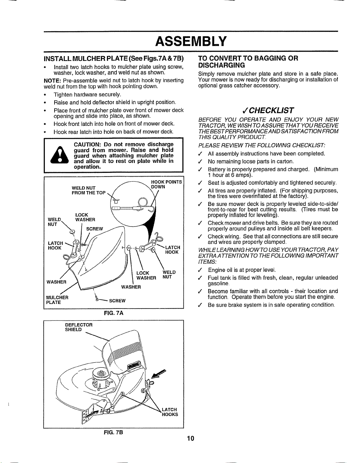
INSTALL MULCHER PLATE (See Figs.7A & 7B)
• Install two latch hooks to rnu[cher plate using screw,
washer, lockwasher, and wetd nut as shown.
NOTE: Pro-assemble weld nut to latch hook by inserting
weld nut from the top with hook pointing down.
. Tighten hardware securely.
• Raise and hold deflector shield in upright position_
° Place front of mulcher plate over front of mower'deck
openingand slide into place, as shown.
° Hook front latch intohote on front of mower deck.
° Hook rear latch into hole on back of mower deck
CAUTION: Do not remove discharge
guard from mower. Raise and hold
&
WELD. WASHER
NUT \-.\
HOOK
WASHER
MULCHER
_LATE
guard when attaching mulcher plate
and allow it to rest on plate while in
operation.
WELD NUT
FROM THE TOP
LOCK
. SCREW
i lllll ii ii ii illllll illl illlll illllllllllllllllll
HOOK PO|NTS
DOWN
HOOK
LOCK WELD
WASHER NUT
WASHER
'_SCREW
FIG. 7A
TO CONVERT TO BAGGING OR
DISCHARGING
Simply remove rnulcherplate and store in a safe place.
Your mower' isnow ready for discharging or installation of
optional grass catcher accessory,
,/CHECKLIST
BEFORE YOU OPERATE AND ENJOY YOUR NEW
TRACTOR, WE WISH TOASSURE THAT YOU RECEIVE
THE BEST PERFORMANCE AND SATISFACTION FROM
THIS QUALITY PRODUCT
PLEASE REVIEW THE FOLLOWING CHECKLIST:
J All assembly instructions have been completed.
,/ No remaining loose parts in carton..
./ Battery isproperly prepared and charged_ (Minimum
1 hour at 6 amps)o
_" Seat is adjusted comfortably and tightened securely.
,/ Atltires are properly inflated. (For shipping purposes,
the tires were overinflated at the factory).
,/ Be sure mower' deck is properly leveied side-to-side/
front-to-rear for best cutting results_ (Tires must be
properly inflated for' leveling),.
,/ Check mower and drive belts. Be sure they are routed
properly around pulleys and inside all belt keepers_
v" Check wiring° See that all connections are still secure
and wires are properlyclamped.
WHILE LEARNING HOW TO USE YOUR TRACTOR, PAY
EXTRA ATTENTION TOTHE FOLLOWING IMPORTANT
ITEMS:
,/ Engine oil is at proper level
,/ Fuel tank is filled with fresh, clean, regular unleaded
gasoline
v" Become familiar with all controls - their location and
function. Operate them before you start the engine.
,/ Be sure brake system is in safe operating condition..
DEFLECTOR
SHIELD
LATCH
HOOKS
FIG. 7B
10

OPEBATmON
i illll
KNOW YOUR TRACTOR
READ THIS OWNER'S MANUAL AND SAFETY RULES BEFORE OPERATING YOUR TRACTOR.
Compare theillustrationswith your tractor tofamiliarize yourself withthe location of various controls and adjustments_ Save
this manual for future reference.
ATTACHMENT CLUTCH LEVER
LIGHT SWITCH
ATTACHMENT
THROTTLE/CHOKE CONTROL
CLUTCH/BRAKE PEDAL
FREEWHEEL
CONTROL
/
HEIGHT ADJUSTMENT
KNOB
Our tractors conform to the safety standards of the American National Standards Institute.,
ATTACHMENT CLUTCH LEVER- Usedto engagemower
blades or other attachments mounted to your tractor_,
ATTACHMENT LIFT LEVER - Used to raise and lower
mower deck or other attachments mounted to your tractor,
CLUTCHtBRAKE PEDAL - Used for declutching and
braking the tractor and starting the engine.
HEIGHT ADJUSTMENT KNOB., Used to adjustthe mower
heighL
LIGHT SWITCH - Turns the headlights on and off_
PARKING BRAKE
MOTION CONTROL LEVER
IGNITEON SWITCH
FIG. 8
FREEWHEEL CONTROL - Disengages transmission for
pushing or slowly towing the tractor with the engine ofE
MOTION CONTROL I.EVER - Selects the speed and
direction of the tractor_
IGNITION SWITCH - Used to start and stop the engine
PARKING BRAKE LEVER - Locks clutch/brake pedal into
the brake position,
THROTTLE/CHOKE CONTROL - Used for starting and
controling engine speed.
LIFT LEVER PLUNGER - Used to release attachment lift
lever when changing its position°
11

,,,, iJlJl,l,l,i
OPERATION
The operation of any tractor can result inforeign objects thrown into the eyes, which can result
in severe eye damage. Always wear safety glasses oreye shields while operating your tractor
or performing any adjustments or repairs. We recommend a wide vision safety mask for over
the spectacles or standard safety glasses.
HOW TO USE YOUR TRACTOR
TO SET PARKING BRAKE (See Fig. 9)
Your tractor isequipped with anoperatorpresencesensing
switch+ When engine is running, any attempt by the
operator to leave the seat without first setting the parking
brake will shut off the engine.
, Depress clutch/brake pedal into full "BRAKE" position
and hold..
• Place parkingbrake lever in"ENGAG ED"position and
release pressure from clutch!brake pedal+Pedalshould
remain in"BRAKE" position+ Make sure parking brake
wilt hold tractor secure.
ATTACHMENT "DISENGAGED"
CLUTCH LEVER
"ENGAGED" POSITION
POSITION
PARKING BRAKE
"ENGAGED"
POSITION
THROTTLE/
CHOKE
LEVER
"BRt KEY
POSITION HEIGHT
CLUTCH/BRAKE "DISENGAGED"
PEDAL "DRIVE" POSITION POSITION
ADJUSTMENT
KNOB PARKING BRAKE
FIG_9
STOPPING (See Fig. 9)
MOWER BLADES -
• Move attachment clutch lever to"DISENGAGED" po-
sition°
GROUND DRIVE -
• Depress clutch/brake pedal intofull "BRAKE" position+
• Move motion control iever to neutral (N) posit+on+
IMPORTANT; THE MOTION CONTROL LEVER DOES
NOT RETURN TO NEUTRAL (N) POSITION WHEN THE
CLUTCH/BRAKE PEDAL IS DEPRESSED
ENGINE +
• Move throttlecontrol to slow (,_) position+
NOTE: Failure to move throttle control to slow (,,_,)
position and allowing engine to idle before stopping may
cause engine to "backfire".+
MOTION
CONTROL
LEVER
IGNITION
• Turn ignition key to "OFF" position and remove key.
Always remove key when leaving tractor +to prevent
unauthorized use+
• Never use choke to stop engine.+
NOTE: Under certain conditions when unit is standing idle
with the engine running, hot engine exhaust gases rnay
cause "browning" of grass+ To elimirlate this possibility,
always stopengine when stopping tractor on grass areas.
CAUTION: Always stop tractor com-
pletely, as described above, before leav-
ing the operator's position; to empty
grass catcher, etc.
TO USE THROTTLE CONTROL (See Fig. 9)
Always operate engine at full throttle.+
* Operating engine at less than full throttle reduces the
battery charging rate+
° Full throttle offers the best bagging and mower perfor-
mance+
TO MOVE FORWARD AND BACKWARD
(See Fig. 9)
The directionand speed of movement is controlledby the
motion controllever+
• Start tractor with motion control lever in neutral (N)
position,.
• Release parking brake and clutch/brake pedat.
• Slowly move motion control lever to desired position.
TO ADJUST MOWER CUTTING HEIGHT
(See Fig. 9)
The cuttingheightiscontrolledby turningtheheight adjust-
ment knob in desired direction+
• Turn knob clockwise ((_) to raise cutting height+
• Turn knob counterclockwise (_) to lower cutting
height.
The cutting height range isapproximately 1-1/2" to 4"+ The
heights are measured from the ground to the blade tip with
the engine not running+ These heights are approximate
and may vary depending upon soil conditions, height of
grass and types of grass being mowed+
• The average lawn should be cutto approximatefy 2-1/2
inches during the cool season and to over 3 inches
during hot rnonths+ For healthier' and better looking
lawns, mow often and after moderate growth.
° For best cutting performance, grass over 6 inches in
height should be mowed twice. Make the first cut
relatively high; the second to desired height.
12

OPERATION
TO OPERATE MOWER (See Fig. 10)
Your tractor is equipped with an operator presence sensing
switch, Any attempt by the operator to leave the seat with
the engine running and the attachment clutch engaged wifl
shut off the engine°
° Select desired height of cut.
° Lower mower with attachment lift control.
° Start mower blades by engaging attachment ck_tch
control.
o TO STOP MOWER BLADES- disengage attachment
clutch control
CAUTION: Do not operate the mower
without either the entire grass catcher,
on mowers so equipped, or the dis-
charge guard in place.
"ENGAGED" POSITION ATTACHMENT
ATTACHMENT
CLUTCH LEVER
"DISENGAGED"
POSITION
FIG. 10
TO OPERATE ON HILLS
CAUTION: Do not drive up or down
hills with slopes greater than 15° and
do not drive across any slope.
. Choose the slowest speed before starting up ordown
hills_
. Avoid stopping or changing speed on hills.
• If slowing is necessary, move throttle control lever to
slower position°
• If stopping is absolutely necessary, pushclutch/brake
pedal quickly to brake position and engage parking
brake°
- Move motion control lever to neutral (N) position°
IMPORTANT: THE MOTION CONTROL LEVER DOES
NOT RETURN TO NEUTRAL (N) POSITION WHEN THE
CLUTCH!BRAKE PEDAL IS DEPRESSED,
, To restart movement, slowly release parking brake and
clutch/brake pedat.
o Slowly move motion control lever to slowest setting.
o Make all turnsslowly
LIFT LEVER HIGH
DISCHARGE
GUARD
TO TRANSPORT
e
Raise attachment lift to highest position with attach-
ment lift control_
o
When pushing or towing your tractor, be sure free-
wheel control is in freewheeling position°
• Do not push or tow tractor at more than five (5) MPH,
NOTE: To protect hood from damage when transporting
your tractor onatruck ora trailer, be sure hood isclosed and
secured totractor. Use anappropriate means of tying hood
to tractor (rope, cord, etc.)
BEFORE STARTING THE ENGINE
CHECK ENGINE OIL LEVEL (See Fig. 18)
. The engine in your tractor has been shipped, from the
factory, already filled with summer weight oil
• Check engine oil with tractor on level ground.
. Unthread and remove oil fill cap/dipstick; wipe oi! off,
Reinsert the dipstick into thetube and restoil _l cap on
the tube. Do notthread the cap onto the tube. Remove
and read oil level. If necessary, add oil until "FULU'
mark on dipstick is reached, Do not overfill
= For cold weather operation you should change oil for
easier starting (See "OIL VISCOSITY CHART" in the
Customer Responsibilities section ofthis manual),
• To change engine oi!, see theCustomer Responsibili-
ties section in this manual
ADD GASOLINE
• Fill fuel tank. Use fresh, clean, regular unleaded
gasoline (Use of leaded gasoline wileincrease carbon
and lead oxide deposits and reduce valve life)o
IMPORTANT: WHEN OPERATING IN TEMPERATURES
BELOW32°F(0°C), USE FRESH, CLEANWINTER GRADE
GASOLINE TO HELP INSURE GOOD COLD WEATHER
STARTING
WARNING: Experience indicates that alcohol blended
fuels (called gasohol or using ethanol or methanol) can
attract moisture which leads to separation and formation of
acids during storage° Acidic gas can damage the fuel
system of an engine while in storage, To avoid engine
problems, the fuel system should be emptied before stor-
age of 30 days or longer. Drain the gas tank, start the
engine and let itrun until the fuel lines and carburetor are
empty. Use fresh fuel next season. See Storage Instruc-
tions for additional information° Never use engine or
carburetor cleaner products in the fuel tank or permanent
damage may occur..
CAUTION: Fill to bottom of gas tank
filler neck. Do not overfill. Wipe off any
spilled oil or fuel Do not store, spill or
use gasoline near an open flame.
13

OPERATION
TO START ENGINE (See Fig. 9)
When starting engine for the first time or if engine has run
out offuel, itwill take extra cranking time to move fuelfrom
the tank to the engine°
• Depress clutch/brake pedal and set parking brake.
• Place motion control lever in neutral (N) position.
° Move attachment clutch to "DISENGAGED" position.
o Move throttle control lever to choke (t\l) position for
cold engine start. Forwarm engine start, movethrottle
control to fast (,_) position..
• Insertkey intoignitionand turnkeyclockwiseto"START"
position and release key as soon as engine starts. Do
not run starter continuously for more than fifteen
seconds per minute. If engine does not start after
several attempts, move throttle control to fast (,_)
position, wait a few minutes and try again.
• When engine starts, slowly move throttle control lever
to desired running speed°
• Allow engine to warm up for a few minutes before
engaging drive or attachments.
IMPORTANT: COLD STARTING FOR HYDRO (BELOW
40=F) - AFTER STARTING ENGINE AND BEFORE
DRIVING, LET TRANSMISSION WARM UP FOR ONE (1)
MINUTE BY PLACING MOTION CONTROL LEVER IN
NEUTRAL (N) POSITION AND RELEASING CLUTCH/
BRAKE PEDAL
NOTE: if at a high altitude (above 3000 feet) or in cold
temperatures (below 32°F), the carburetor fuel mixture
may need tobeadjusted for best engine performance.. See
'q'O ADJUST CARBURETOR" inthe Service and Adjust-
ments section of this manual.
MOWING TIPS
• Tire chains cannot be used when the mower housing
is attached to unit..
• Mower' should be,property leveled for best mow!ng
performance., See 'TO LEVEL MOWER HOUSING in
the Service and Adjustments section of this manual.
• The Lefthand side of mower should be used for trim-
ming.
• Ddve so that clippings are discharged onto the area
that has been cut. Have the cut area to tile right ofthe
machine. This will resultina more even distribution of
clippings and more uniform cutting.
• When mowing large areas, start by turning to the right
so that clippings will discharge away from shrubs,
fences, driveways, etc. After one or two rounds, mow
in the opposite direction making left hand turns until
finished (See Fig. 11).
° tf grass is extremely tall, it should be mowed twice to
reduce load and possible fire hazard from dried clip-
pings. Make first cut relatively high; the second to the
desired height.
• Do not mow grass when it iswet. Wet grass will ptug
mower and leave undesirable clumps Allow grass to
dry before mowing.
• Always operate engine at full throttle when mowing to
assure better mowing performance and proper dis-
charge of material. Regulate ground speed by select-
ing a low enough gear' to give the mower cutting
performance as welt as the quality of cut desired°
• When operating attachments, select a ground speed
that will suit the terrain and give best perforrnance of
the attachment being used..
.
,i,i i
FIG. 11
MULCHING MOWING TIPS
IMPORTANT: FOR BEST PERFORMANCE, KEEP
MOWER HOUSING FREE OF BUILT-UP GRASS AND
TRASH_ CLEAN AFTER EACH USE..
• The special mulching blade will recut the grass clip-
pings many times and reduce them in size so that as
they fall onto the lawn they will disperse intothe grass
and not be noticed. Also, the mulched grass will
biodegrade quickly to provide nutrients for the lawn.
Always mulch with your' highest engine (blade) speed
as this will provide the best recutting action of the
blades.
• Avoid cutting your lawn when it iswet° Wet grass tends
to formclumps and interferes with the mulching action.
The best time to mow your lawn isthe early aflernoon_
At this time the grass has dried and the newly cut area
will not be exposed to the direct sun.
Forbest results, adjustthe mower cutting height sothat
tt)e mower cuts off only the top one-third of the grass
blades (See Fig, 12). For extremely heavy mulching,
reduce your width ofcut on each pass and mow slowly_
• Certain types of grass and grass conditions may re-
quire that an area be mulched a second time to com-
pletely hide the clippings. When doing a second cut,
mow across or perpendicular' to the first cut path.
• Change your cutting pattern from week to week. Mow
northto south one week then change to eastto west the
next week This will help prevent matting and graining
of the lawn.
MAX 1/3
FIG. 12
14

CUSTOMER RESPONSUBILITHES
mmw_,_,*_"_"_' ' "ll.............. !ll"lI '"' _"!I _'_,,u, ! ,,,';,,','_l,_,J,',"l'"'l"!'J ! , '! "" _ _ _ _ -
sc. oo. "
AS YOU COMPLETE _)£,_ _4t,_. £x_ _- _'*_ _ _4_-' O__
._REGu RSERV, E...................................................__................. RV!OEDATES
Check Brake Operation V #
Check'nreP';e$_'ur'e....... iV"..... V' ..........
T Check for Loose'Fasteners ........... _ ........ 6#4 .....
R Sharpen/Replace Mower Blades ...... 6/4
A Lubdcaii0n Chart .............. _ .........
T Check Battery L,ev,eVRecharge .............. $f .............. ......
0 Clean Battery and Terminals ......................... 6#4 6#4
R Check Transaxfe Cooling _ .............
Adjust Blade Beit(s) Tension .......... 6#t5 .
Adjust Motion Drive Belt(s) Tension _5
.... Check Engine Oil Level _' V #'
=Change Engine Oil .................. _ ...... _I,2,3 ,.....
Clean Air Filter 6#_'_ ........ ,
E Clean Air Screen .....iiii,iiiii, _2 ................... .....
G inspect Muffler/SparkArrester 6_
eP'iaceOii"F,ter ,i' 'e o'ppedi...................... iii..... .................
.......... , =,
N Clean Engine Cooling Fins"' 6_2 ......................
R_p!,,_cesparkPiiUg ............................... e,' v' ..............
Replace Air Filter Paper Cartridge ................... , .....
Replace Fuel Filter tL,-'/
1-Changemore oftenwhenoperatingundera heavy loadorin high ambienttemperatures 3 - IIequippedwithoil filter,changeoilevery50 hours
2-Service mote often when operatingin dirtyordustyconditions 4- Replacebfadesmore often when mowing insandysoll
GENERAL RECOMMENDATIONS
The warranty on thistractor does not cover items that have
been subjected to operator abuse or negligence,, To
receive full value from the warranty, operator mustmaintain
tractor as instructed in this manual,
Some adjustments witi need to be made periodically to
properly maintain your tractor,
All adjustments in the Service and Adjustments section of
this manual should be checked at least once each season,
• Once a year you should replace the spark plug, clean
or replace air filter, and check blades and belts for
wear,. A new spark plug and clean air filter assure
proper air-fuel mixture and help your engine run better
and last longer_
BEFORE EACH USE
o Check engine oil level,
• Check brake operation,
• Check tire pressure.,
• Check for Ioose fasteners,
(_)SPtNDLE ZERK_ SPINDLE ZERK (_)
®
CLUTCH PIVOT
(_)CHECKiADD
PUMP FLUID
(_SAE 30 OR 10W30 MOTOR OIL AP| - SG
(_)GENERAL PURPOSE GREASE
(_)REFER TO CUSTOMER RESPONSIBILITIES "ENGINE" SECTION
IMPORTANT; DO NOT OIL OR GREASE THE PIVOT POINTS
WHICH HAVE SPECIAL NYLON BEARINGS, VISCOUS LUBRI-
CANTS WILL ATTRACT DUST AND DIRT THAT WILL SHORTEN
THE LIFE OF THE SELF-LUBRICATING BEARINGS, 1F YOU
FEEL THEY MUST BE LUBRICATED, USE ONLY A DRY, POW-
15 DERED GRAPHITE TYPE LUBRICANT SPARINGLY,
5- 1!equippedwith adjustablesyslem
LUBRICATION CHART
ONT WHEEL (_)
BEARING ZERK
CUSTOMER RESPONSIBILITIES
TRACTOR
Always observe safety rules when performing any mainte-
nance.
BRAKE OPERATION
If tractor requires more than six (6)feet stopping distance
at highspeed inhighest gear, then brake must be adjusted
(See "TO ADJUST BRAKE" in the Service and Adjust-
ments section of this manual)
TIRES
• Maintain proper air pressure in alt tires (See "PROD-
UCT SPECIFICATIONS" on page 3 of this manual),
= Keep tires free of gasoline, oil, or insect control chemi-
cals which can harm rubber_
• Avoid stumps, stones, deep ruts_sharp objects and
other hazards that may cause tire damage.
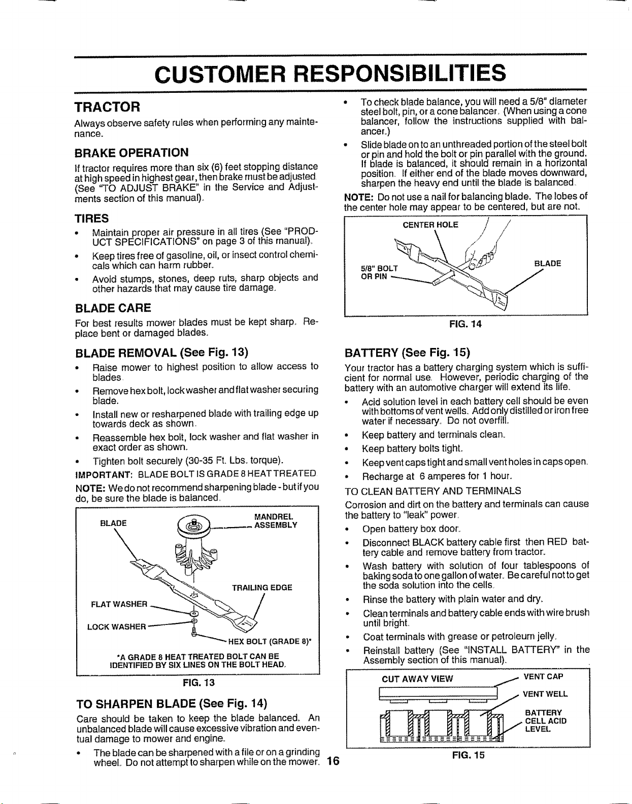
BLADE CARE
For best resufts mower blades must be kept sharp_ Re-
place bent or damaged blades.
BLADE REMOVAL (See Fig. 13)
• Raise mower to highest position to allow access to
blades
• Remove hexbolt, lock washer andflat washer securing
blade.
• Install new or'resharpened blade with trailing edge up
towards deck as shown,
• Reassemble hex bolt, lock washer and flat washer in
exact order as shown.
• Tighten bolt securely (30-35 Ft. Lbs,torque).
IMPORTANT: BLADE BOLTISGRADE 8HEATTREATED
NOTE: We do not recommend sharpening blade- but ifyou
do, be sure the blade isbalanced
__ MANDREL
BLADE__ _- ASSEMBLY
*A GRADE 8 HEAT TREATED BOLT CAN BE
IDENTIFIED BY SIX LINES ON THE BOLT HEAD.
FIG. 13
TO SHARPEN BLADE (See Fig. 14)
Care shouid be taken to keep the blade balanced, An
unbalancedblade willcause excessivevibrationand even-
tual damage to mower and engine.
• The blade can be sharpened with afile oron agrinding
wheel Do not attemptto sharpen while on the mower°
• To checkblade balance, you will need a 5/8" diameter
steel bolt, pin,ora cone balancer, (When using a cone
balancer, follow the instructions supplied with bal-
ancer,)
• Slide blade on toanunthreaded portion ofthe steet bolt
or pin and hold the bolt orpin parallel with the ground.
if biade is balanced, it should remain in a horizontal
position If either' end of the blade moves downward,
sharpen the heavy end until the blade is balanced
NOTE: Donot use anail for balancing blade. The lobes of
the center hole may appear to be centered, but are not.
CENTER HOLE / /'
\ / /
FIG. 14
BATTERY (See Fig. 15)
Yourtractorhas a battery charging system whichis suffi-
cient for normal use. However, periodic charging of the
battery withan automotive chargerwilt extend itslife,
• Acid solution levef in each battery cell should be even
withbottoms ofventwells_Add onlydistilled oriron free
water'if necessary_, Do not overfillo
• Keep battery and terrninatsclean°
• Keep battery bolts tight.
• Keepvent caps tight and small vent holes in capsopen.
° Recharge at 6 amperes for 1 hour_
TO CLEAN BATTERY AND TERMINALS
Corrosion and dirt on the battery and terminals can cause
the battery to "leak" power.
• Open battery box door'.
• Disconnect BLACK battery cable first then RED bat-
tery cable and remove battery from tractor°
• Wash battery with solution of four tablespoons of
baking sodato onegallon ofwater_Be careful notto get
the soda solution into the cells_
• Rinse the battery with plain water and dry.
• Clean terminals and battery cable ends with wire brush
until bright,
° Coat terminals with grease or petroleurn jelly,
• Reinstall battery (See "INSTALL BATTERY" in the
Assembly section of this manual)_
CUTAWAY VIEW / VENTCAP
VENT
BATTERY
CELL ACID
LEVEL
16
FIG. 15
WELL

CUSTOm' ER RESPONSl
V-BELTS ENGINE
Check V-belts for deterioration and wear after 100 hours of
operation and replace if necessary_ The belts are not
adjustable, Replace belts ifthey begin to slip from wear_
TRANSAXLE COOLING (See Fig. '16)
The fan and cooling fins of transmission should be kept
clean to assure proper cooHng_
Donot attempt to clean fan or transmission while engine is
running or while the transmission is hot.
• inspect cooling fan to besure fan blades are intact and
clean.,
= Inspect cooling fins for dirt, grass clippings and other
materials.
TRANSAXLE PUMP FLUID LEVEL
(See Figs. 16 & 17)
Checkfluid level after every25 hours ofuse, Reardrawbar
must be removed to check fluid level
= Remove the four (4) fasteners to removethe drawbar.
° Clean reservoir thoroughlybefore removing cap.
o Check for proper fluid fevel in reservoir (should be
above the "OIL LEVEL COLD" line),.
o if oil is needed, remove cap on reservoir (with a
clockwise rotation), and fill to "OIL LEVEL COLD" line
with SAE 10W30 oi! (API - SG),
• Replace cap securely (do not overtighten)_
Reassemble drawbar and tighten fasteners securely.
RESERVOIR
"OIL LEVEL HOT" LINE
LEVEL COLD" LINE
COOLING FAN
COOLING
FINS
FIG. 16
LUBRICATION
Only use high quality detergent oil rated with AP! service
classification SG,, Select the oil's SAE viscosity grade
according to your expected operating temperature..
°c-3o' ..... _20[.....t_o" .....o" 1o° 20" 3oo 4o"
TEMPERATURE RANGE ANTICIPATED BEFORE NEXT OIL CHANGE
NOTE: Although multi-viscosity oils (5W30, 10W30 etc)
improvestarting incold weather, these multFviscosity oils
will result in increased oil consumption when used above
32°F. Check your engine oil level more frequently to avoid
possible engine damage from running low on oiI_
Change the oil after the first two hours of operation and
every 50 hours thereafter or at least once a year if the
tractor is not used for 50 hours in one year..
Check the crankcase oil level before starting the engine
and after each eight (8) hours of operation. Tighten oil fill
cap/dipstick securely each time you check the oil level.,
TO CHANGE ENGINE OIL (See Fig, 18)
Determine temperature range expected before oHchange..
All oil must meet API service classification SG
= Be sure tractor is on level surface,
o
Oil will drain more freely when warm.
o
Catch oil in a suitable container,
o
Remove oilfill cap/dipstick_ Be careful not 1oallow dirt
to enter the engine when changing oil
o
Remove drain plug,
o
After oil has drained completely, replace oil drain plug
and tighten securely.
Refill engine with oil through oil fill dipstick tube, Pour
slowly, Do not overfill. For approximate capacity see
"PRODUCT SPECIFICATIONS" on page 3 of this
]
manual
Use gauge on oil fill cap/dipstick for checking level,
insert dipstick into the tubeand restthe oil fill cap onthe
tube. Do notthread the cap onto the tube when taking
reading Keep oil at "FULL" line on dipstick, Tighten
cap onto the tube securely when finished
L THES
SAEWSCOSITVGRADES
17
CUSTOMER RESPONSIBILITIES
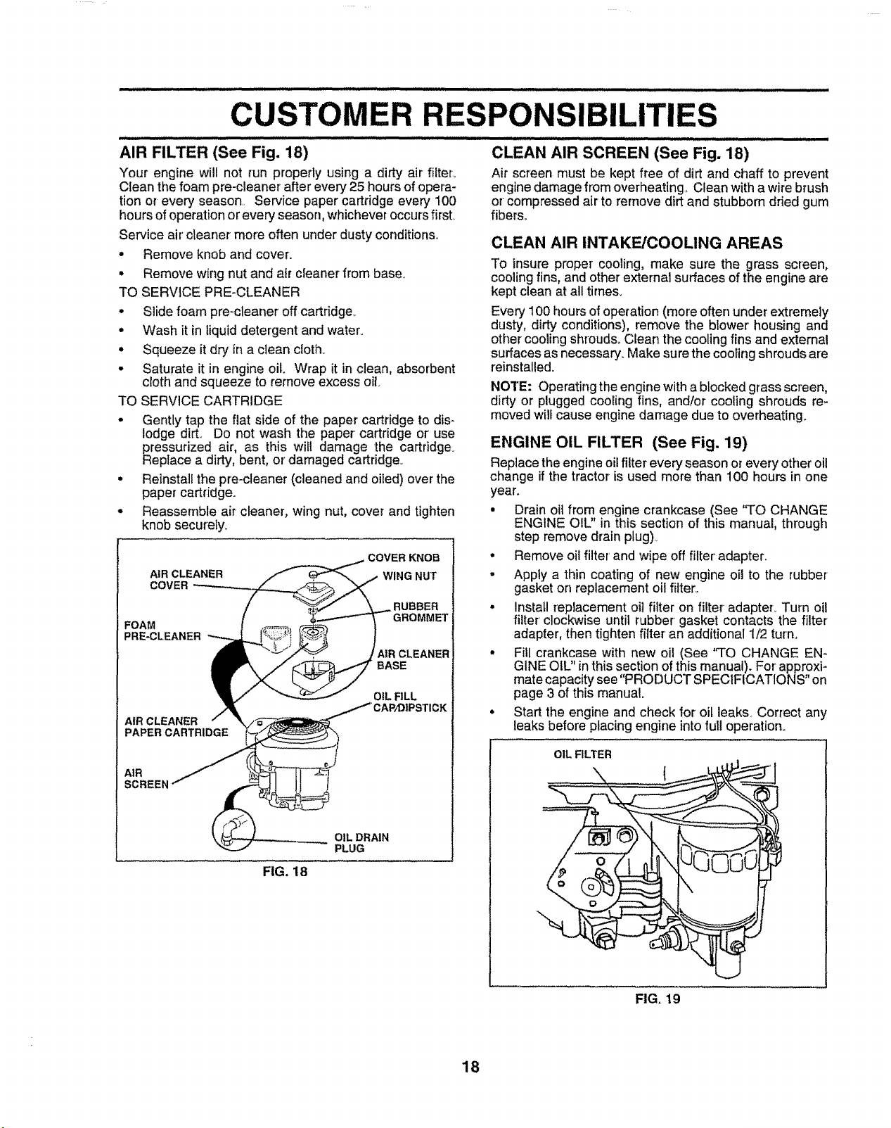
AIR FILTER (See Fig. 18)
Your engine will not run properly using a dirty air filter_
Clean the foam pre-cleaner after every 25 hours of opera-
tion or ever':/season. Service paper cartridge every 100
hours of operationor every season, whichever occurs first.
Service air'cleaner more often under dusty conditions.
• Remove knob and cover.
• Remove wing nut and air cleaner from baser
TO SERVICE PRE-CLEANER
• Slide foam pre-cleaner off cartridge°
• Wash it inliquid detergent and water°
• Squeeze it dry in a clean cloth_
• Saturate it in engine oil. Wrap it inclean, absorbent
cloth and squeeze to remove excess oil.
TO SERVICE CARTRIDGE
° Gently tap the fiat side of the paper cartridge to dis-
lodge dirt,. Do not wash the paper cartridge or use
pressurized air, as this will damage the cartridge.
Reptace a dirty, bent, or damaged cartridge°
• Reinstai! the pre-cleaner (cleaned and oiled) over the
paper cartridge.
° Reassemble air cleaner, wing nut, cover and tighten
knob securely.
COVER KNOB
AIR CLEANER
COVER
FOAM
PRE-CLEANER
AIR CLEANER
PAPER CARTRIDGE
AIR
WING NUT
RUBBER
GROMMET
AIR CLEANER
BASE
OIL FILL
CLEAN AIR SCREEN (See Fig. 18)
Air screen must be kept free of dirt and chaff to prevent
enginedamagefrom overheating,,CIean witha wirebrush
or compressedair to remove dirt and stubborn dried gum
fibers_
CLEAN AIR INTAKE/COOLING AREAS
To insure proper cooling, make sure the grass screen,
cooling fins, and other external surfaces of the engine are
kept clean at all times_
Every 100 hours of operation (more often under extremely
dusty, dirty conditions), remove the blower housing and
other cooling shrouds_ Cfean the cooling fins and external
surfaces asnecessary. Make sure the cooFingshrouds are
reinstalled.
NOTE: Operating the engine with a blocked grass screen,
dirty or plugged cooEingfins, and/or cooling shrouds re-
moved wilf cause engine damage due to overheating.
ENGINE OIL FILTER (See Fig. 19)
Replace the engineoilfilter every season or every other oil
change ifthe tractoris used more than 100 hours in one
year..
- Drain oil from engine crankcase (See "TO CHANGE
ENGINE OIL" in this section of this manual, through
step remove drain plug)..
• Remove oil filter and wipe off filter' adapter..
- Apply a thin coating of new engine oil to the rubber
gasket on replacement oil filter..
• Install replacement oi] filter on filter adapter_ Turn oil
filter clockwise until rubber' gasket contacts the filter
adapter', then tighten filter an additional 1/2 turn.,
° Fill crankcase with new oil (See "TO CHANGE EN-
GINE OIL" inthis section of this manual). For approxi-
mate capacity see "PRODUCT SPECIFICATIONS" on
page 3 of this manual_
• Start the engine and check for oil leaks. Correct any
leaks before placing engine into furl operation_
OIL FILTER
FIG, 18
OIL DRAIN
PLUG
FIG, 19
18
 Loading...