

Craftsman 917255440 Owner’s Manual

SEA/_S
CRnFTSMnN
MODEL NUMBER 917.255440 OWNER'SMANUAL
• Assembly
• Operation
• Customer
Responsibilities
r m
Se.vice91
! AdjuStments
Repair _arf_
Caution:
Read and Follow
all Safety Rules
and Instructions
Before Operating
This Equipment
lit....

Safe Operation Practices for Ride-On Mowers
SAFETY RULES
IMPO RTANT: THIS CUTTIN G MAC HINE IS CAPABLE OFA MPUTATING HAN DSAN DFEET ANDTH ROWING OBJECTS.
FAILURE TO OBSERVE THE FOLLOWING SAFETY INSTRUCTIONS COULD RESULT IN SERIOUS INJU RY OR DEATH.
! GENERAL OPERATION
, Read, understand, and follow all instructions in the manual
and on the machine before starting.
, Only allow responsible adults, who are familiar with the
instructions, to operate the machine.
, Clear the area of objects such as rocks, toys, Wire, etc.,
which could be picked up and thrown by the blade.
, Be sure the area isclear of other people before mowing. Stop
machine ifanyone enters the area.
° Never carry passengers.
• Do not mow in reverse unless absolutely necessary. Always
look down and behind before and while backing.
• Be awar_of the mower discharge direction and do not point
it at anyone. Do not operate the mowe[.wthout either the
entire grass catcher orthe guard in place.
, Slow down before turning.
• Never leave a running machine unattended. Always turn off
blades, set parking brake, stop engine, and remove keys
before dismounting.
• TLa'n off blades when not mowing.
; Stopengine b#fore removing grass catcher or unclogg_hg
chute,
• ' _W
oMO oniyin daylight orgood artificial4ig_t. '
• Do not operate the machin e white Under the influence of
. _ alCel_01or drugs. : -
._ _W_tch fortraffiC when operatihg nea,r o¢_rossing roadways.
• : Use extra care when loading.o€ unloading the machine into
•a_a!le.r or tr(__,_.
II. SLOPE oPERATIONZ
Slopes _.re .a major factor related to loss-of-centre! and t=pover
accidents, which can respltjr_ severe injury or death. All slopes
require extra caution. Ify0u cannot backup the slope orifyou feel
uneasy on it, _o not mow it. ....
DO:
• Mow up_anu uovyp_pes, nor across.
• Remove obstaC!_s such as rocks, tree limbs, etc.
• Watch for boles, ruts, or bumps. Uneven terrain could
overturnth_,machine. Tall grass can hide obstacleg; :.-
• Use slowspeed. Choosea Iowgear so that you will nct have
to stop or shi_ while on the slope.
• Follow the roanufacturer's recommendations for._'_ne_l
weights or counterweights to improve stability. ..,
• Use extra care with grass catchers or other attachments.
These can change the stability of the machine.
• Keepallmovementontheslopess/owandgradual. Donot
make sudden changes in speed or direction.
• Avoid starting or stopping on a slope. If tires lose traction,
disengage the blades and proceed slowly straight down the
slope.
DO NOT:
• Do not turn on slopes unless necessary, and then, turn slowly
and gradually downhill, if possible.
• Do not mow near drop-offs, ditches, or embankments• The
mower could suddenly tum over if a wheel is over the edge
of a cliff or ditch, or if an edge caves in.
• Do not mow on wet grass. Reduced traction could cause
sliding.
• Donot try to stabilize the machine by putting your foot on the
ground.
• Do not use grass catcher on steep slopes•
Ill. CHILDREN
Tragic accidents can occur if the operator is not alert to the
presence of children. Children are often attracted to the machine
and the mowing activity. Neverassume that children will remain
where you last saw them.
• Keep children out ofthe mowing area and under the watchful
care of another responsible adult.
• Be alert and turn machine off if children enter the area.
• Before and when backing, look behind and down for small
children.
• Never carry children. They may fall off and be seriously
injured or interfere with safe machine operation.
= Never allow_childrent_ operate the machine.. •
• Use extra care when approaching blind corners, s_ubs,
trees, or other objects that may obscure vision.
IV. SERVICE
• Use extra care inhandling gasoline and other fuels _hey are
flammable and vapors are explosive.
Use on!y an approved container.
Never remove gas cap or add fuel with the engine
running. Allow engine _ocool before refueling. DOn0!
smoke. ..
Never refuel the machine indoors.
Never store_the machine or fuel conta_iner inside where
•t[te_ i_ an Open flame such as a water heat_,.
• Never _ru#a machin_ inside a closed area,
• Keep huts and boffs, especially blade attachment belts,.tight
._ . and keep equipment in good €ondition_._
• NeVer tamper with safety device_. ' Check their propel"
oper_t on regularly.. : ......
_,, KeepmachinefreeOfgrass leaves 0rotherdebrisbuild-up.
Clean oil or fuel spjl!_ge. Allow machine to cool before
storing. , _"
• Stop and inspect the °_quipment if you strike an object.
Repair, f necessary, before r_ta_ing.
• Ne_,er make adjustmpnts or rePair_ with the engine running.
• Grass catcher componen:ts°are subject to wear, damage and
deterioration, which ¢o_ldexpose moving parts or allow
objects to be thrown.. Frequently check components and
replace with manufacturer's recommended parts, when nec-
essary.
• Mower blades are sha_p_can cut. Wrap the blade(s) or
wear gloves, and use extra caution when servicing them.
• Check brake operation frequently. Adjust and service as
required.
Look for this symbol to point out impor-
tant safety precautions. It means
CAUTION!!! BECOME ALERT!_! YOUR
SAFETY IS INVOLVED.
CAUTION: Always disconnect spark
plug wire and place wire where it cannot
&
contact spark plug in order to prevent
accidental starting when setting up,
transporting, adjusting or making
repairs.
2

CONGRATULATIONS on your purchase of a Sears
Tractor. It has been designed, engineered and manufac-
tured to give you the best possible dependability and
performance.
Should you experience any problem you cannot easily
remedy, please contact your nearest Sears Authorized
Service Center/Department. We have competent, well-
trained technicians and the proper tools to service or repair
this unit.
Please read and retain this manual. The instructions will
enable you to assemble and maintain your unit properly.
Always observe the "SAFETY RULES",
MODEL
NUMBER 917.255440
SERIAL
NUMBER
DATEOFPURCHASE
THE MODELANDSERIALNUMBERSWlLLBEFOUND
ON A PLATE UNDER THE SEAT.
YOU SHOULD RECORD BOTH SERIAL NUMBER AND
DATE OF PURCHASE AND KEEP lN A SAFE PLACE
FOR FUTURE REFERENCE.
PRODUCT SPECIFICATIONS
HORSEPOWER: 12.5
GASOLINE CAPACITY 5 QUARTS
AND TYPE: UNLEADED REGULAR
OIL TYPE (API-SG): SAE 30 (above 32°F)
SAE 5W-30 (below 32°F)
OIL CAPACITY: W/O FILTER: 3.0 PINTS
SPARK PLUG: CHAMPION RJ-19LM
(GAP: .0XX") STD361458
VALVE CLEARANCE: INTAKE: .005" - .007"
EXHAUST: .009" - .011"
GROUND SPEED (MPH): FORWARD:
1st 1.00
2nd 1.50
3rd 2.00
4th 3.00
5th 4.20
6th 5.00
REVERSE: 1.50
TIRE PRESSURE: FRONT: 14PSI
REAR: 12 PSI
CHARGING SYSTEM: 3 AMPS BATTERY
5 AMPS HEADLIGHTS
BLADE BOLT TORQUE: 30-35 FT. LBS.
MAINTENANCE AGREEMENT
A Sears Maintenance Agreement is available on this prod-
uct. Contact your nearest Sears store for details.
CUSTOMER RESPONSIBILITIES
• Read and observe the safety rules.
= Follow a regular schedule in maintaining, caring for and
using your unit.
• Follow the instructions under "Customer Responsibili-
ties" and "Storage" sections of this owner's manual.
WARNING: This unit is equipped with an internal combus-
tion engine and should not be used on or near any unim-
proved forest-covered, brush-covered or grass-covered
land unless the engine's exhaust system is equipped with
a spark arrestor meeting applicable local or state laws (if
any): If aspark arrestor is used, it should be maintained in
effective working order by the operator.
In the State of California the above is required by law
(Section 4442 of the California Public Resources Code).
Other states may have similar !aws. Federal laws apply on
federal lands. A spar k arrestor for the muffler is available
through your nearest Sears Authorized Service Center/
Department (See REPAIR PARTS section of this manual).
LIMITED TWO YEAR WARRANTY ON ELECTRIC START RIDING EQUIPMENT
For two (2) years from the date of purchase, if this riding equipment is maintained, lubricated and tuned up according to the
instructions in the owner's manual, Sears will repair or replace, free of charge, any parts found to be defective in material or
workmanship.
This Warranty does not cover:
• Expendable items which become worn during normal use, such as blades, spark plugs, air cleaners and belts.
', Tire replacement or repair caused by punctures from outside objects, such as nails, thorns, stumps, or glass.
• Repairs necessary because of operator abuse, negligence, improper storage or accident or the failure to maintain the
equipment according to the instructions contained in the owner's manual.
• Riding equipment used for commercial or rental purposes.
LIMITED 90 DAY WARRANTY ON BATTERY
For ninety (90) days from date of purchase, if any battery included with this riding equipment proves defective in material or
workmanship and our testing determines the battery will not hold a charge, Sears will replace the battery at no charge.
WARRANTY SERVICE iS AVAILABLE BY RETURNING THE RIDING EQUIPMENT TO THE NEAREST SEARS SERVICE
CENTER/DEPARTMENT IN THE UNITED STATES.
This Warranty gives you specific legal rights, and you may also have other rights which may vary from state to state.
SEARS, ROEBUCK AND CO., D/817 WA, HOFFMAN ESTATES, ILLINOIS 60179
3

TABLE OF CONTENTS
SAFETY RULES ............................................................ 2
PRODUCT SPECIFICATIONS ...................................... 3
CUSTOMER RESPONSIBILITIES ..................... 3, 15-19
WARRANTY .................................................................. 3
TABLE OF CONTENTS ......................... ....................... 4
INDEX ............................................................................ 4
TRACTOR ACCESSORIES .......................................... 5
ASSEMBLY .............................................................. 7-10
OPERATION .......................................................... 11-14
MAINTENANCE SCHEDULE ...................................... 15
SERVICE AND ADJUSTMENTS ............................ 20-25
STO RAG E ................................................................... 26
TROUBLESHOOTING .;........................... . ............. 26-27
REPAIR PARTS - TRACTOR ................................ 30-47
REPAIR PARTS ENGINE .................................... 48-52
PARTS ORDERI _G/SERVICE .................. BACK PAGE
INDEX
A
Accessories ............................................ 5
Adjustments:
Brake .......................................... 22
Carburetor ................................... 25
Mower:
Front-To-Back ........................ 21
Side-To-Side .......................... 21
Throttle Control Cable ................. 24
Air Filter Engine .............. _................. 18
Air Screer. Engine ............................. 18
Assembly ................................... :....7-10
B
Battery:
Charging ....................................... 8
Cleaning ...................................... 17
Installation ......_................................ 9
Levels .............................. _....... 8,17
Preparation ........................... _....:...8
Starting with Weak Battery .:........ 23
Storage ....................................... 26
Terminals ....... :................... :........ 17
Belts:
Motion Drive
Removal!Replacement ........... 22
Mower Blade Drive
Removal/Replacement ........... 22
Blade:
Shan3ening ................................. 16
Replacement ............................... 16
Brake Adjustment .............................. 22
C
CarburetorAdjustment ....................... 25 M
Controls• Tractor ................................ 11 Maintenance Schedule ..................... i. 15
Castomer Responsibilities ............. 15-19
Engine:
Air Filter .................................. 18
Air Screen, Engine .................. 18
Battery .................................... 17
Cooling Fins, Engine ............... 18
Engine Oil ............................... 17
Fuel Filter ................................ 19
Spark Plugs ............................. 19
Tractor:
Blades ..................................... i 6
Lubrication Chart ..................... 15
Maintenance Schedule ............ 15
Tire Care ......................... 8,16,23
Cutting Height, Mower ......................... 12
Electrical:
interlocks and Relays .................. 24
Schematic ................................... 29
Wiring Diagram ........................... 30
Engine:
Air Filter ...................................... 18
Air Screen ................................... 18
Cooling Fins, Engine ................... 18
Oil Change .................................. 17
Oil Level ................................. 13.17
Oil Type ...................................... 17
Preparation ............................... :. 13
Repair Parts ............ _............ 48-52
Starting ..................................... 14
Storage ................o....................... 26
=liters:
Air ............................. _................. 18
Fuel ................................ :............. 1
Fuel:
Type ........... i................................ '13
Storage ................................ _....... 26
Fuse ................................................... 24
Gauge Wheels ..................................... 9
I-I_od Removal/Installation ................. 24
Leveling Mower Deck ......................... 21
Lubrication Chart ................................ 15
Mower:
Adjustment, Front-to-Back .......... 21
Adjustment, Side-to-Side ............ 21
Blade Sharpening ....................... 16
Blade Replacement ..................... 16
Cutting Height ............................. 12
Installation ................................... 20
Operation .................................... 13
Removal ...................................... 20
Mowing Tips ....................................... 14
Muffler ................................................ 19
Spark Arrester .......................... 3,40
Mulcher Plate ..................................... 10
E
F
G
H
L
4
O
Oil:
Cold Weather Conditions ....... 13,17
Engine ......................................... 17
Storage ....................................... 26
Operation ...................................... 11-14
Operating Mower ............................... 13
Options:
Accessories .................................. 5
Spark Arrester .......................... 3.40
P
Parking Brake ............................... 11-12
Parts Bag .................................. :.......... 6
Parts Replacement/Repair ........... 30-47
Product Specifications ........................... 3
R
Repair Parts ...... _.......................... 30-47
S
Safety Rules ....: .................................... 2
'Seat ............................................ ,........ 8
Service and Adjustments ............. 20-25
Brake .......................................... 22
Carburetor ................................... 25
Fuse ............................................ 24
Hood Removal/InstalFation .......... 24
Motion Drive Belt
Removal!Replacement ........... 22
Mower Blade Drive Belt
Removal/Replacement ........... 22
Mower Adjustment:
Front-to-Back ......................... 21
Side-to-Side ........................... 21
Mower Installation ....................... 20
Mower Remova! .......................... 20
Tire Care ............................. 8,16,23
Slope Guide Sheet ............................. 55
Spark Plugs ........................................ 19
Specifications ....................................... 3
Starting the Engine ....................... 13-14
Steering Wheel ................................ 7,23
Stopping the Tractor ........................... 12
Storage .............................................. 26
T
Throttle Control Cable Adjustment .....24
Tires ........................................... 8,16,23
Trouble Shooting Chart .................. 26-27
Transaxle Repair Parts ................. 46-47
W
Warranty .......................................... _...3
Wiring Diagram .................................. 30
Wiring Schematic ............................... 29

J
ACCESSORIES AN ATTACHMENTS
These accessories and attachments were available throug h most Sears retail outlets and service Centers when the tractor was purchased.
Most Sears stores can order these items for you when you provide the model number of your tractor.
ENGINE
f SPARK PLUG GAS CAN ENGINE OIL FUEL STABILIZER
MAINTENANCE
BLADES BELTS
PERFORMANCE
Sears offers a wide variety of attachments that fit your tractor. Many of these are listed below with brief explanations of how they can help
you. This list was current at the time of publication; however, it may change in future years - more attachments may be added, changes
may be made in these attachments, or some may no longer be available or fit your model. Contact your nearest Sears store for the
accessories and attachments that are available for your tractor.
Most of these attachments do not require additional hitches or conversion kits (those that do are indicated) and are designed for easy
attaching and detaching.
AERATOR promotes deep root growth for a healthy lawn. Ta-
pered 2.5-inch steel spikes mounted on 10-inch diameter discs
puncture holes in soil at close intervals to let moisture soak in.
Steel weight tray for increased penetration.
BAGGER lets you collect grass clippings and leaves for a
healthier, heater looking lawn. Two Permanex containers hold
30-gal!on plastic bags.
BUMPER protects front end of tractor from damage.
CARTS make hauling easy. Variety of sizes available, p!us
accessories such as side panel kits, tool caddy, cart cover,
protective mat and dolly.
CORING AERATOR takes small plugs out of soil to allow mois-
ture and nutrients to reach grass roots. 36-inch swath. 24
hardened steel coring tips. 150 lb. capacity weight tray.
EASY OIL DRAIN VALVE makes oil changes easier, faster.
FRONT NOSE ROLLER canters in front of mower deck to reduce
chanoes of "scalping" on uneven terrain.
GANG HITCH lets you tow 2 or 3 pull-behind attachments at once,
such as sweepers, dethatchers, aerators (not for use with rollers,
carts or other heavy attachments).
GAUGE WHEELS on both sides of the mower deck reduce
chances of "scalping" on uneven terrain. For mower decks not so
equipped.
MULCH RAKF_.JDETHATCHER loosens soil and flips thatch and
matted leaves to lawn surface for easy pickup. Twenty spring tine
teeth. Usefuitoprepare bareareasforseeding. Availableforfront
or rear mounting. HiGH PERFORMANCE REEL-ACTION
SPRING TINE DETHATCHER covers 36-inch wide path and
tosses thatch into large hopper. Mounts behind tractor.
MULCHING KiT, once installed, lets you mulch, discharge or bag
clippings (bagger optional) without changing blades. For models
not equipped as 3-in-1 Convertible mowers.
RAMP TOPS AND FEET let you load and unload tractor from a
pickup truck. Use with 2 x 8 or 2 x 10 lumber.
ROLLER for smoother lawn surface. 36-inch wide, 18-inch
diameter water-rig ht drum holds up to 3901be. ofweight. Rounded
edges prevent harm to turf. Adjustable scraper automatically
cleans drum.
SNOW BLADE forsnow removal only. 14-inch high, 42-inch wide
blade clears 38-inch path when angled left or right, Raises, lowers
with side lever. Adjustable skids; replaceable, reversible scraper
bar. (Use with tire chains and wheel weights and/or rear drawbar
weight.)
SNOWTHROWER has 40-inch swath. Drum-type auger handles
powdery and wet/heavy snow. Mounts easily with simple pin
arrangement, Discharge chute adjusts from tractor seat. 6-inch
diameter spout discharges snow 10 to 50 feet. Lift controlled at
tractor seat. (Use with chains and wheel weights an_'or rear
drawbar weight.)
SPRAYERS use 12-volt DC electric motor that connects to the
tractor battery or other 12-volt source. Includes booms for
automatic spraying and hand held wand for spot spraying. Wand
has adjustable spray pattern. For applying herbicides, insecti-
cides, fungicides and liquid fertilizers.
SPREADERISEEDERS make seeding, fertilizing, and weed kill-
ing easy. Broadcast spreaders are also useful for granular de-
icers and sand.
SWEEPERS let you collect grass clippings and leaves.
TILLER has 5hp engine and 36-inch swath to prepare seed beds,
cultivate and compost garden residue. Tiller has its own built-in
lift and depth control system and does NOT require a sleeve hitch.
Fits any lawn, yard or garden tractor. Simply hook up to the tractor
drawbar and go[ Optional accessories convert unit for
dethatching, aerating, hilling...without tools.
TIRE CHAINS are heavy duty; closely spaced extra-large cross
links give smooth ride, outstanding traction.
TRACTOR CAB has heavy duty vinyl fabric over tubular steel
frame, ABe plastic top; clear plastic windshield offers 360 degree
visibility. Hinged meta[ doors with catch. Keeps operator warm
and dry. Remove vinyl sides and windshields for use as sun
protector in summer. Optional accessories include: tinted/
tempered solid safety glass windshield with hand operated wiper;
12-volt amber caution light for mounting on cab top.
VACS for powerful collection of heavygrass clippings and leaves.
Optional wand attachment to pick up debris in hard-to-reach
places. VAC/CHIPPER includes a chipper-shredder.
WEIGHT BRACKET for drawbar for snow removal applications.
Uses (1) 55 lb. weight.
WHEEL WEIGHTS for rear wheels provide needed traction for
snow removal or dozing heavy materials.
5

CONTENTS OF HARDWARE PACK
Parts Bag contents shown full size
\
(1) Locknut 3/8-24
(1) Large Flat Washer
(1) Shoulder Bolt 5/16-18
(1) Hex Bolt 1/2-13 x 1.
I (2) Sheet
Metal
Screws
#10-16 x 1/2
Parts packed separately in carton
O
Seat
Battery acid
Mulcher
/ Plate
Steering
Wt-eel
Steering
Boot
Battery
(_@
(1) Lock Washer 1/2
(1) Washer 17/32 x 1-3/16x 12 Gauge
@
(2) Screws #10 x 5/8 (2) Lock Washers #10
(2) Weld Nuts #10 <
(2) Washers 3/16 x 3/4 x 16 Gauge
(2) Hex Bolts 1/4.20 x 3/4
(2) Washers 9/32 x 5/8 x 16 Gauge
@
(2) Hex Nuts 1/4-20
(2) Lock Washers 1/4
Owner's Manual Parts Bag
Parts bag contents not shown full size
(2) Shoulder (2) Locknuts
Bolts 3/8-16
(2) Gauge
Wheels
_i s Steering
_ Wheel
Insert
Latch Hook
Assemblys
I-_ ' .......I
15° Slope Sheet
Steering Wheel
Adapter
_ teering
€
(2) Keys
[I
/ \
and Instructions
Bushing
h .... /
=[
1 ,
.......... h
Battery Caps
I
ASSEMBLY
Your new tractor has been assembled at the factory with exception Ofthose parts left unassembled for shipping purposes.
To ensure safe and proper operation of your tractor all parts and hardware you assemble must be tightened securely. Use
the correct tools as necessary to insure proper tightness.
TOOLS REQUIRED FOR ASSEMBLY
A socket wrench set will make assembly easier. Standard
wrench sizes are listed.
(1) 5/16" wrench
(2) 7/16" wrenches
(1) 3/4" wrench
(1) 9/16" wrench
Tire pressure gauge
Phillips Screwdriver
Utility knife
(1) 1/2" wrench
When right and left hand are mentioned in this manual, it
means when you are in the operating position (seated
behind the steering wheel).
TO REMOVE TRACTOR FROM CARTON
UNPACK CARTON
• Remove all accessible loose parts and parts cartons
from carton (See page 6).
• Cut along lines on carton, from top to bottom, all four
corners of carton and lay panels flat.
* Check for any additional loose parts or cartons and
remove.
BEFORE ROLLING TRACTOR OFF SKID
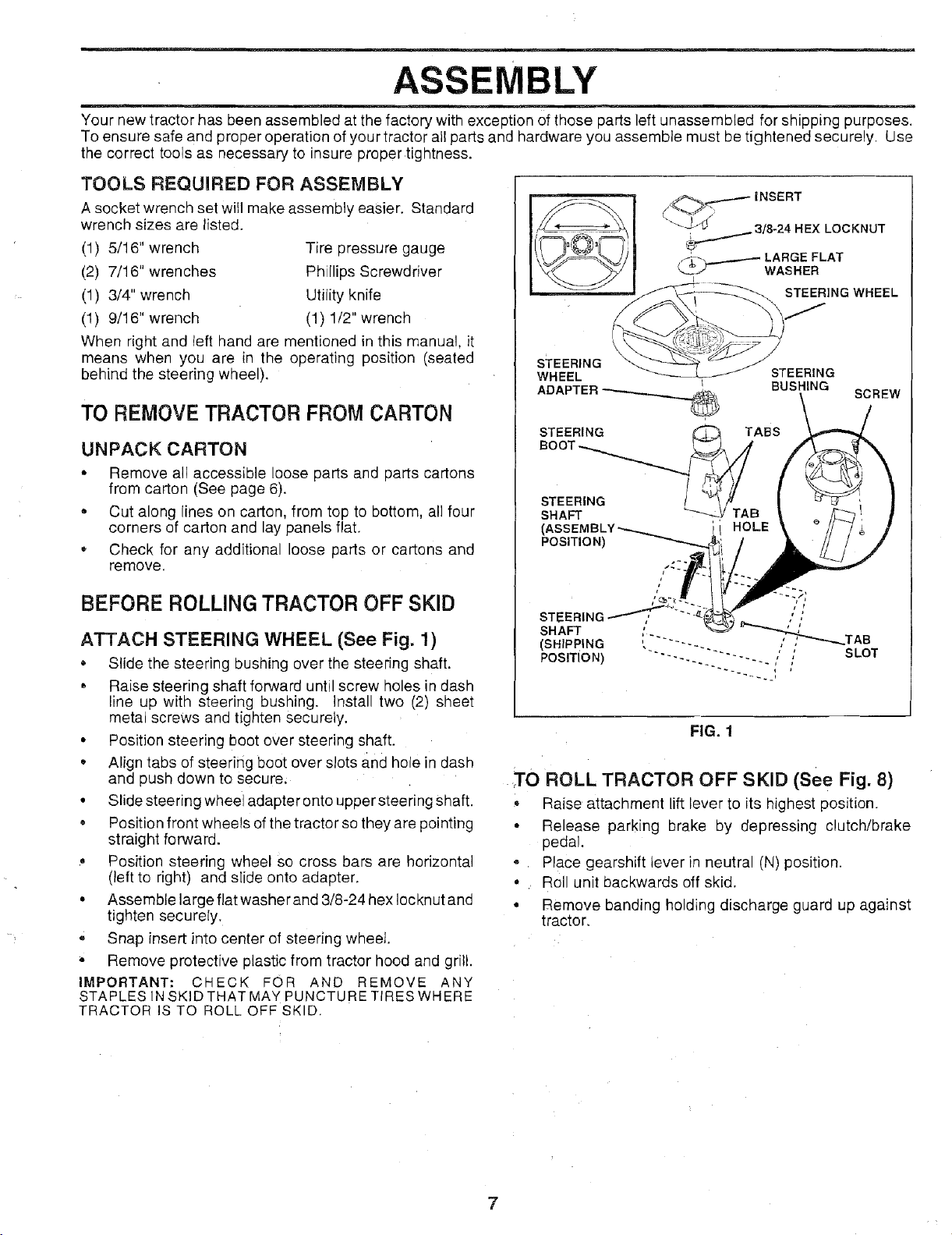
ATTACH STEERING WHEEL (See Fig. 1)
• Slide the steering bushing over the steering shaft.
• Raise steering shaft forward until screw holes in dash
line up with steering bushing. Install two (2) sheet
metal screws and tighten securely.
• Position steering boot over steering shaft.
,, Align tabs of steerifig boot over slots and hole in dash
and push down to secure.
• Slide steering wheel adapter onto upper steering shaft.
• Position front wheels of the tractor so they are pointing
straight forward.
• Position steering wheel so cross bars are horizontal
(left to right) and slide onto adapter.
• Assemble large flat washer and 3/8-24 hex Iocknut and
tighten securely.
= Snap insert into center of steering wheel.
• Remove protective plastic from tractor hood and grill.
IMPORTANT: CHECK FOR AND REMOVE ANY
STAPLES IN SKIDTHAT MAY PUNCTURE TIRES WHERE
TRACTOR IS TO ROLL OFF SKID.
INSERT
.._._3/8-24 HEX LOCKNUT
f._. _ LARGE FLAT
L_.J"'- WASHER
STEERING WHEEL
sTEERING
WHEEL I
ADAPTER __ BUSHING
STEERING TABS
BOOT
STEERING /
SHAFT _-_ 3
(, 'i HOLE
POSITION)
STEERING ,'/,"
SHAFT
(SHIPPING " ......
POSITION) ---. "'" ' ,' SLOT
" ,, ; _-_._.TAB
~~.
STEERING
SCREW
FIG. 1
TO ROLL TRACTOR OFF SKID (See Fig. 8)
,, Raise attachment lift lever to its highest position.
• Release parking brake by depressing clutch/brake
pedal
* 1 Place gearshift lever in neutral (N) position.
• Roll unit backwards off skid.
• Remove banding holding discharge guard up against
tractor.
7

ASSEMBLY
HOW TO SET UP YOUR TRACTOR
PREPARE BATTERY (See Fig. 2)
CAUTION: Wear eye and face shield.
Wash hands or clothing immediately if
accidentally in contact with batteryacido
Do not smoke. Fumes from charged
battery acid are explosive. Read the
instructions included with the battery
vent caps. Always wear gloves, cloth-
ing and goggles to protect your hands,
skin and eyes.
Your tractor has a battery charging system which is suffi-
cient for normal use. However, periodic charging of the
battery with an automotive charger will extend its life.
• See instructions packed with vent caps in oarts bag.
• Fill battery with acid. Fill each ce unti it reaches the
bottom .of the vent wells. Do not overfill.
Allow battery to stand ana settle for at east thirty
minutes. After standing, check the eve! df acid. If
below the vent Wells, add more acid until the correct
level is reached.
While battery is standing (after adding acid) and later, while
battery isbeing charged, continue with assembly of tractor.
IMPORTANT: TO MAXIMIZE THE LIFE OF YOUR
BATTERY, IT IS NECESSARY THAT THE BATTERY BE
CHARGED BEFORE USE. FAILURE TO CHARGE
BATTERY., CAN RESULT IN A SHORTEI_ED BATTERY
LIFE.
" Chargebattery at a rate of 6 amperes for 1 hour. Use
a 12 volt batteb' charger. Observe all safety orecau-
tions required for battery charging.
• Check the acid eve after the battery is charged If tne
acid has fallen below the correct evel, add distilled or
iron free water.
• install the veni caps to cover the vent wells. Wash the
top of the battery with water to remove any acid. then
wipe dry.
• Check batte_' Case for leakage to maKe sure that no
damage has occurred in handling.
° Dispose of excess battery acid. Neutralize acid for
disposal by adding it to two gallons of water in a five
gallon plastic container. Stir with a wooaen or plastic
paddle while adding baking soda until the addition of
more soda causes no more foaming.
Follow instructions on how to install battery,
CUT AWAY VIEW /VENT CAP
BATTERY
CELL ACID
VENT WELL
LEVEL
FIG. 2
INSTALL SEAT (See Fig. 3)
Adjust seat before tightening adjustment bolt.
. Remove cardboard packing on seat pan.
• Place seat on pan and assemble shoulder bolt.
• Assemble adjustment bolt, Iockwasher and fiat washer
loosely. Do not tighten.,
• Tighten shoulder bolt securely.
Lower seat into operating position and sit on seat,
Slide seat until a comfortable position is reached which
allows you to press clutch/brake pedal all the way down
(See Fig. 8).
, Get off seat without moving its adjusted Position.
• Raise seat and tighten adjustment bolt securely.
SEAT
\
SEAT PAN
\
SHOULDER
BOLT
I
I
ADJUSTMENT
BOLT
LOCKWASHER
FIG. 3
CHECK TIRE PRESSURE
The tires on yoL rtractor were overinflated at the factory for
shipping purposes, Correct tire pressure is important for
best cutting performance.
o Reduce tire pressure to PSI shown n "PRODUCT
SPECIFICATIONS" on page 3 of this manual
CHECK DECK LEVELNESS
For best cutting results, mower housing should be properly
leveled. See "TO LEVEL MOWER HOUSING" in the
Service and Adjustments section of this manual.
CHECK FOR PROPER POSITION OF ALL
BELTS
See the figures that are shown for replacing motion and
mower blade drive belts in the Service and Adjustments
section of this manual, Verify that the belts are routed
correctly.
CHECK BRAKE SYSTEM
After you learn how to operate your tractor, check to see
that the brake is properly adjusted. See "TO ADJUST
BRAKE" in the Service and Adjustments section of this
manual.
4ER

INSTALL BATTERY (See Figs. 4 & 5)
CAUTION: Do not short battery termi-
nals. Before installing battery, remove
rings, etc.
metal bracelets; wristwatch bands,
Positive terminal must be connected
first to prevent sparking from acciden-
tal grounding.
Lift seat to raised position.
Open battery box door.
• Be sure battery drain tube is attached to battery box.
° Lower battery into battery box with battery terminals
toward front of tractor.
_- First connect RED battery cable to positive (+) battery
terminal with hex bolt, flat washer, lock washer and hex
nut as shown. Tighten securely.
• Connect BLACK grounding cable to negative (-) bat-
tery terminal with remaining hex bolt, flat washer, lock
washer and hex nut, Tighten securely.
• Close battery box door.
Open battery box door for:
• inspection for secure connections (to tighten hard-
ware).
• Inspection for corrosion.
• Testing battery.
• Jumping (if required).
° Periodic charging.
BATTERY
BOXDOOR
BOX DOOR
VENT CAPS
FiG. 5
ASSEMBLE GAUGE WHEELS TO MOWER
DECK (See Fig.6)
Assemble gauge wheels with tractor on aflat, level surface.
• Adjust mower to desired cutting height (See 'q-O AD-
JUST MOWER CUTTING HEIGHT" in the Operation
section of this manual).
• With mower in desired height of cut position, gauge
wheels shoutd be assembled Sothey are slightly off the
ground. Install gauge wheel in appropriate hole with
shoulder bolt and 3/8-16 Iocknut and tighten securely.
• Repeat for opposite side installing gauge wheel in
same adjustment hote.
POSITIVE NEGATIVE
(RED) CABLE (BLACK) CABLE
LOCK WASHER
POSITIVE (+) TERMINAL NEGATIVE (-) TERMINAL
FIG.4
GAUGE WHEEL _._\ "_-_MOUNTING
BRACKET \
\
FIG. 6
9

ASSEMBLY
iNSTALL MULCHER PLATE
(See Figs. 7A & 7B)
• Install two latch hooks to mulcher plate using screw,
washer, lock washer, and weld nut as shown.
NOTE: Pre-assemble weld nut to latch hook by inserting
weld nut from the top with hook pointing down.
, Tighten hardware securely.
• Raise and hold deflector shield in upright position.
o Place front of mulcher plate over front of mower deck
opening and slide into place, as shown.
- Hook front latch into hole on front of mower deck.
, Hook rear latch into hole on back of mower deck.
CAUTION: Do not remove discharge
guard from mower. Raise and hold
guard when attaching mulcher plate
and allow it to rest on plate while in
operation.
DEFLECTOR ,.///'_
SHIELD
FIG. 7B
LATCH
HOOKS
WELD NUT FROM THE TOP HOOK POINTS DOWN
LOCK
WELD WASHER
SCREW
HOOK
WELD
NUT
WASHER
MULCHER
PLATE
LOCK
WASHER
WASHER
SCREW
FIG. 7A
TO CONVERT TO BAGGING OR DISCHARG-
ING
Simply remove mulcher plate and store in a safe place.
Your mower is now ready for discharging or installation of
optional grass catcher accessory.
v"CHECKLIST
BEFORE YOU OPERATE AND ENJOY YOUR NEW
TRACTOR, WE WISH TO ASSURE THAT YOU RECEIVE
THE BEST PERFORMANCEAND SATISFACTION FROM
THIS QUALITY PRODUCT.
PLEASE REVIEW THE FOLLOWING CHECKLIST:
,/ All assemblyi_nstructions have been completed.
,/ No remaining loose parts in carton.
,/ Battery is properly prepared and charged. (Minimum
• 1 hour at 6 amps).
,/ Seat is adjusted comfortably and tightened securely.
,/ All tires are properly inflated. (For shipping purposes,
the tires were overinflated at the factory).
,/ Be sure mower deck is properly leveled side-to.side/
front-to-rear for best cutting results. (Tires must be
properly inflated for leveling).
,/ Check mower and drive belts. Be sure they are routed
properly around pulleys and inside all belt keepers•
,/ Check wiring. See that all connections are still secure
and wires are properly clamped.
WHILE LEARNING HOW TO USE YOUR TRACTOR, PAY
EXTRA A TTENT!ON TO THE FOLLOWING IMPORTANT
ITEMS:
,/ Engine oil is at proper level.
v" Fuel tank is filled with fresh, clean, regular unleaded
gasoline.
,/ Become familiar with all controls - their location and
function. Operate them before you start the engine.
¢" Be sure brake system is in safe operating condition.
10

OPERATION
KNOW YOUR TRACTOR
READ THIS OWNER'S MANUAL AND SAFETY RULES BEFORE OPERATING YOUR TRACTOR
Compare the illustrations with your tractor to familiarize yourself with the locations of various controls and adjustments. Save
this manual for future reference.
LIFT LEVER PLUNGER
LIGHT SWITCH
THROTTLE/CHOKE
CONTROL
LUTCH EVER
CLUTCH/BRAKE
PEDAL
T
HEIGHT
ADJUSTMENT
KNOB
Our tractors conform to the safety standards of the American National Standards Institute.
ATTACHMENT CLUTCH LEVER: Used to engage the
mower b ades, or other attachments mounted to your
tractor.
LIGHT SWITCH: Turns the headlights on and off.
THROTTLE!CHOKE CONTROL: Used for starting and
controlling engine speed.
CLUTCH/BRAKE PEDAL: Used fordectutching and brak-
ing the tractor and starting the engine.
PARKING BRAKE: Locks clutch/brake pedal into the
brake position.
BRAKE
GEARSHIFT
ER
IGNITION
TCN
FIG. 8
GEARSHIFT LEVER: Selects the speed and direction of
tractor.
ATTACHMENT LIFT LEVER: Used to raise and lower the
mower deck or other attachments mounted to your tractor.
LIFT LEVER PLUNGER: Used to release attachment lift
lever when changing its position.
IGNITION SWITCH: Used for starting and stopping the
engine.
HEIGHTADJUSTMENT KNOB: Used to adjust the mower
cutting height.
OPERATION
The operation of any tractor can result in foreign objects thrown into the eyes, which can result
in severe eye damage. Always wear safety glasses or eye shields while operating your tractor
or performing any adjustments or repairs. We recommend wide vision safety mask-for over
the spectacles or standard safety glasses, available at Sears Retail or Catalog stores.
HOW TO USE YOUR TRACTOR
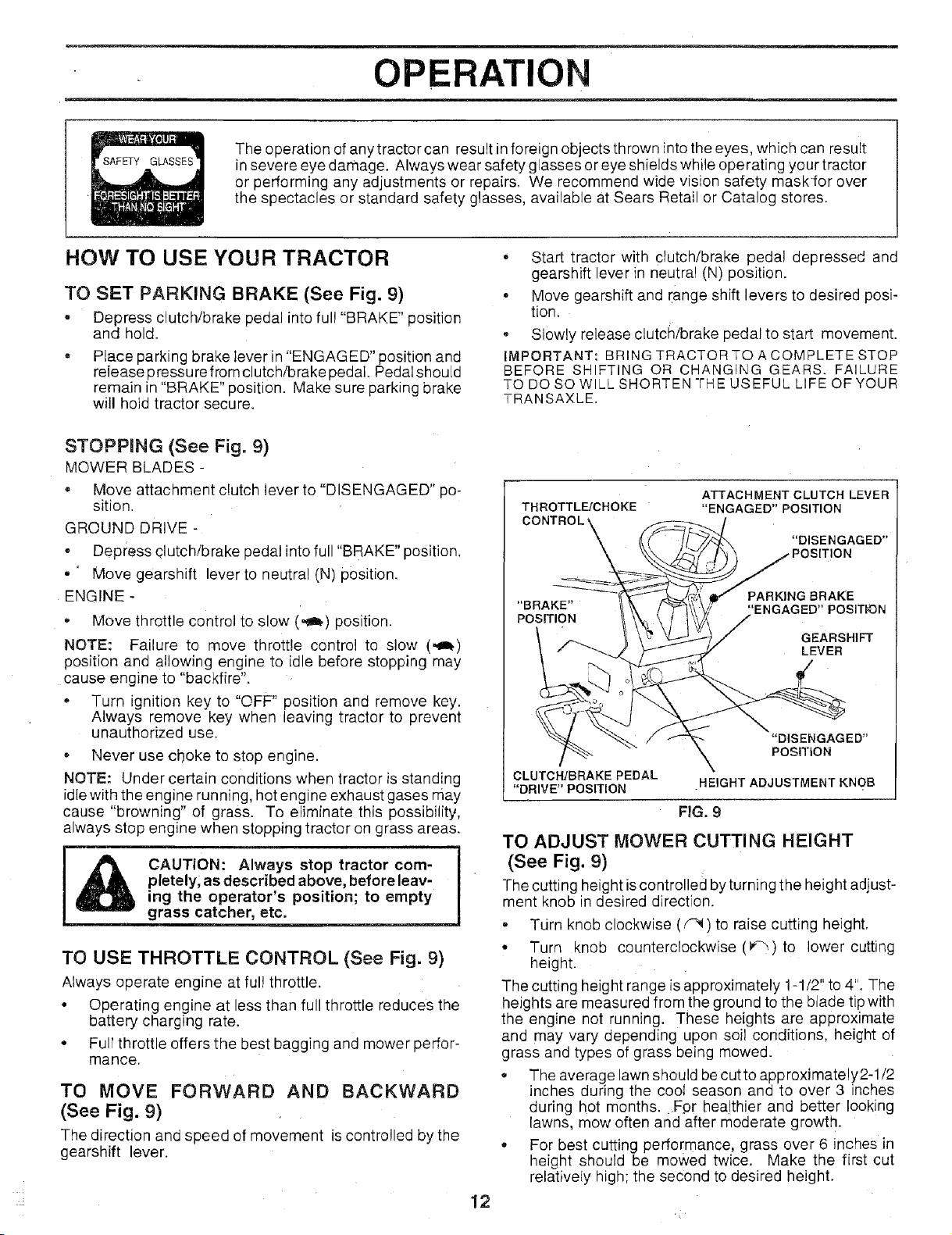
TO SET PARKING BRAKE (See Fig. 9)
= Depress clutch/brake pedal into ful! "BRAKE" position
and hold.
PIace parking brake lever in "ENGAGED" position and
release pressure from clutch/brake pedal. Pedal should
remain in "BRAKE" position. Make sure parking brake
will hoid tractor secure.
STOPPING (See Fig. 9)
MOWER BLADES -
• Move attachment clutch lever to "DISENGAGED" po-
sition.
GROUND DRIVE -
- Depress clutch/brake pedal into full "BRAKE" position.
• ' Move gearshift lever to neutral (N) position.
ENGINE -
, Move throttle control to slow (_) position.
NOTE: Failure to move throttle control to slow (,_)
position and allowing engine to idle before stopping may
cause engine to "backfire".
• Turn ignition key to "OFF" position and remove key.
Always remove key when leaving tractor to prevent
unauthorized use.
* Never use choke to stop engine.
NOTE: Under certain conditions when tractor is standing
idle with the engine running, hot engine exhaust gases may
cause "browning" of grass. To eliminate this possibility,
always stop engine when stopping tractor on grass areas.
CAUTION: Always stop tractor com-
pletely; as described above, before leav-
ing the operator's position; to empty
grass catcher, etc.
TO USE THROTTLE CONTROL (See Fig. 9)
Always operate engine at ful! throttle.
° Operating engine at less than full throttle reduces the
battery charging rate.
• Full throttle offers the best bagging and mower perfor-
mance.
TO MOVE FORWARD AND BACKWARD
(See Fig. 9)
The direction and speed of movement is controlled by the
gearshift lever.
, =
° Start tractor with clutch/brake pedal depressed and
gearshift lever in neutra! (N) position.
° Move gearshift and range shift levers to desired posi-
tion.
* Slowly release clutch/brake pedal to start movement.
IMPORTANT: BRING TRACTOR TO A COMPLETE STOP
BEFORE SHIFTING OR CHANGING GEARS. FAILURE
TO DO SO WILL SHORTEN THE USEFUL LIFE OF YOUR
TRANSAXLE.
THROTTL_CHOKE
"BRAKE" 'ENGAGED" POSIThON
POSITION
CLUTCH/BRAKE PEDAL
"DRIVE" POSITION
ATTACHMENT CLUTCHLEVER
"ENGAGED"POSITION
"DISENGAGED"
)SITION
PARKING BRAKE
GEARSHIFT
LEVER
"DISENGAGED"
PosmoN
HEIGHT ADJUSTMENT KNOB
FIG. 9
TO ADJUST MOWER CUTTING HEIGHT
(See Fig. 9)
l-he cutting height iscontrolled by turning the height adjust-
ment knob in desired direction.
° Tdrn knob clockwise (_) to raise cutting height.
• Turn knob counterclockwise (_) to lower cutting
height.
The cutting height range is approximately 1-1/2" to 4". The
heights are measured from the ground to the blade tip with
the engine not running. These heights are approximate
and may vary depending upon soil conditions, height of
grass and types of grass being mowed.
° The average lawn should be cutto approximately2-1/2
inches during the coot season and to over 3 inches
during hot months. Fpr hea!thier and better looking
lawns, mow often and after moderate growth.
° For best cutting performance, grass over 6 inches in
height should be mowed twice. Make the first cut
relatively high; the second to desired height.
12

OPERATION
TO OPERATE MOWER (See Fig. 10)
You rtractor is equipped with an operator presence sensing
switch. Any attempt by the operator to leave the seat with
the engine running and the mower dutch engaged will shut
off the engine.
= Select desired height of cut.
Lower mower with attachment lift control.
,, Start mower blades by engaging attachment clutch
control.
• TO STOP MOWER BLADES - disengage attachment
clutch control.
CAUTION: Do not operate the mower
without either the entire grass catcher,
&
ATTACHMENT CLUTCH LEVER
"DISENGAGED" POSITION
on mowers so equipped, or the dis-
charge guard in place.
"ENGAGED"
POSITION
"'_ LOW
ATTACHMENT
ER
HIGH POSITION
POSITION
Move gearshift lever to 1st gear and be su re you have
allowed room for tractor to roll slightly as you restart
movement.
o
To restart movement, slowly release parking brake and
clutch/brake pedal.
Make all turns slowly.
TO TRANSPORT
• Raise attachment lift to highest position with attach-
ment lift control.
• When pushing or towing your tractor, be sure gearshift
lever is in neutral (N) position.
• Do not push or tow tractor at more than five (5) MPH.
NOTE: To protect hood from damage when transporting
your tractor on a truck or atrai]er, be sure hood isclosed and
secured totractor. Use an appropriate means of tying hood
to tractor (rope, cord, etc.).
BEFORE STARTING THE ENGINE
CHECK ENGINE OIL LEVEL (See Fig. 16)
• The engine in your tractor has been shipped from the
factory already filled with summer weight oil.
• Check engine oil with tractor on level ground.
• Remove oil fill dipstick and wipe clean, replace and
screw cap tight, wait for a few seconds, remove and
read oi! level. If necessary, add eil until "FULL" mark
on dipstick is reached. Do not overfill.
• For cold weather operation you should change oil for
easier starting (see "OIL VISCOSITY CHART" in the
Customer Responsibilities section of this manual).
• To change engine oil, see the Customer Responsibili-
ties section in this manual.
FIG. 10
TO OPERATE ON HILLS
hills with slopes greater than 15° and
CAUTION: Do not drive up or down
do not drive acrbss any slope.
o
Choose the slowest speed before starting up or down
hills.
Q
Avoid stopping or changing speed on hills.
®
If slowing is necessary, move throttle control lever to
slower position.
If stopping is absolutely necessary, push clutch/brake
pedal quickly to brake position and engage parking
brake.
7
13
ADD GASOLINE
• Fill fuel tank. Use fresh, clean, regular unleaded
gasoline. (Use of leaded gasolinewill increase carbon
and lead oxide deposits and reduce valve life).
IMPORTANT: WHENQPERATINGINTEMPERATURES
BELOW 32°F(0°C), USE FRESH, CLEAN WINTER GRADE
GASOLINE TO HELP INSURE GOOD COLD WEATHER
STARTING.
WARNING: Experience indicates that alcohol blended
fuels (called gasohol or using ethanol or methanol) can
attract moisture which leads to separation and formation of
acids during storage. Acidic gas can damage the fuel
system of an engine while in storage. To avoid engine
problems, the fuel system should be emptied before stor-
age of 30 days or longer. Drain the gas tank, start the
engine and let it run until the fuel lines and carburetor are
empty. Use fresh fuel next season. See Storage Instruc-
tions for additional information. Never use engine or
carburetor cleaner products in the fuel tank or permanent
damage may occur.
CAUTION: Fill to bottom of gas tank
filler neck. Do not overfill. Wipe off any
spilled oil or fuel. Do not store, spill or
use gasoline near an open flame.
OPERATIO
TO START ENGINE (See Fig. 9)
When starting engine for the first time or if engine has run
out of fuel, it will take extra cranking time to move fuel from
the tank to the engine.
• Depress clutch/brake pedal and set parking brake.
• Place gearshift lever in neutral (N) position.
• Move attachment clutch to "DISENGAGED" position.
• Move throttle control lever to choke (I\1) position for
cold engine start. For warm engine start, move throttle
control to fast (,t_) position.
• Insert key into ignition and turn keyclockwise to"START"
position and release key as soon as engine starts. Do
not run starter continuously for more than fifteen
seconds per minute. If engine does not start after
several attempts, move throttle control to fast (._)
position, wait a few minutes and try again.
- When engine starts, move throttle control to desired
position.
• Allow engine to warm up for a few minutes before
engaging drive or attachments.
NOTE: If at a high altitude (above 3000 feet) or in cold
temperatures (below 32°F), the carburetor fuel mixture
may need to be adjusted for best engine performance. See
"TO ADJUST CARBURETOR" in the Service and Adjust-
ments section of this manual.
MOWING TIPS
• Tire chains cannot be used when the mower housing
is attached to tractor.
. Mower should be properly leveled for best mowing
performance. See "TO LEVEL MOWER HOUSING" in
the Service and Adjustments section of this manual.
• The left hand side of mower should be used for trim-
ming.
• Drive so that clippings are discharged onto the area
that has been cut. Have the cut area to the right of the
tractor. This will result in a more even distribution of
clippings and more uniform cutting.
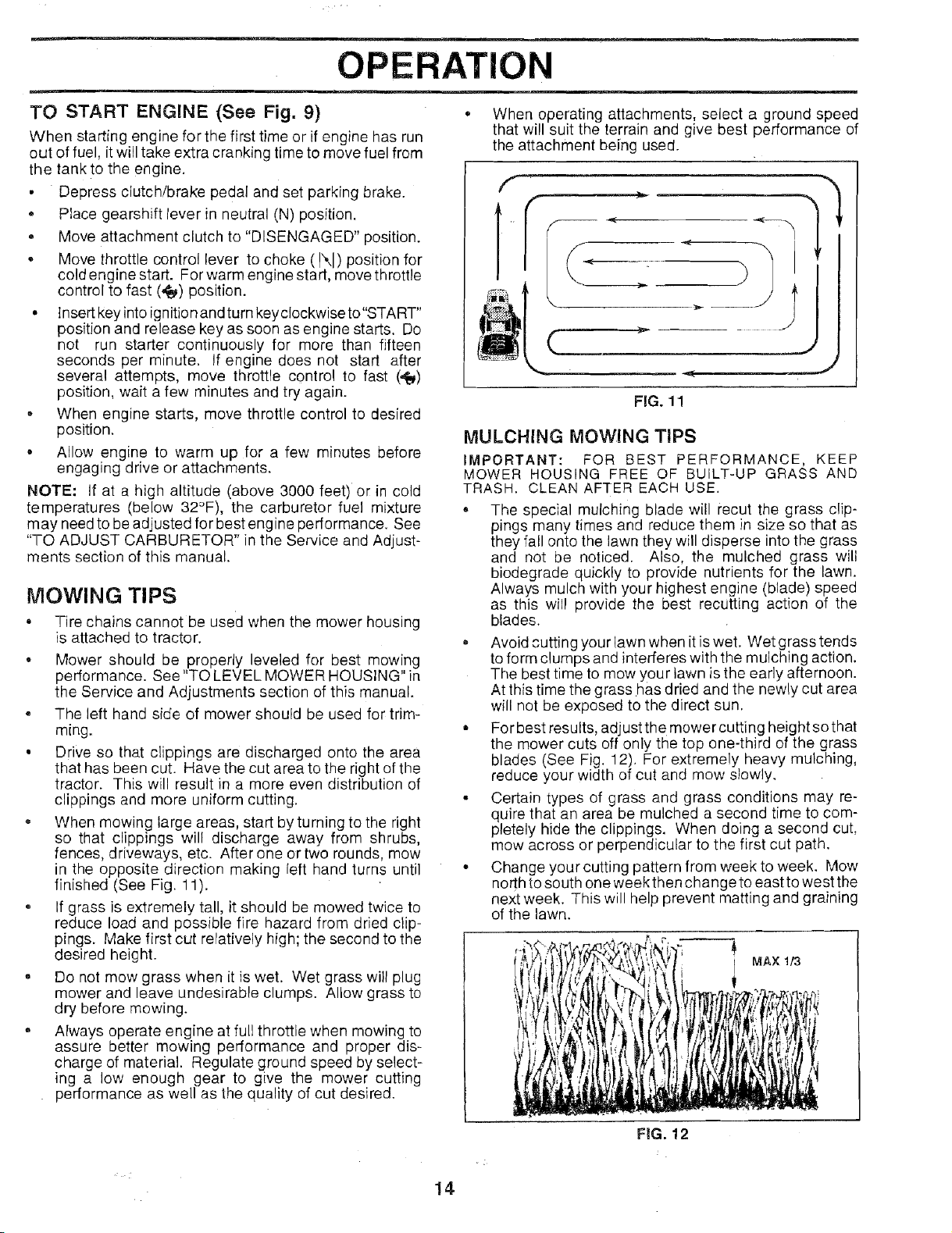
, When mowing large areas, start by turning to the right
so that clippings will discharge away from shrubs,
fences, driveways, etc. After one or two rounds, mow
in the opposite direction making left hand turns until
finished (See Fig. 11).
. If grass is extremely tall, it should be mowed twice to
reduce load and possible fire hazard from dried clip-
pings. Make first cut reratively high; the second to the
desired height.
= Do not mow grass when it is wet. Wet grass will plug
mower and leave undesirable clumps. Allow grass to
dry before mewing.
• Always operate engine at full throttle when mowing to
assure better mowing performance and proper dis-
charge of material. Regulate ground speed by select-
ing a low enough gear to give the mower cutting
performance as well as the quality of cut desired.
• When operating attachments, select a ground speed
that will suit the terrain and give best performance of
the attachment being used.
f
w _ -J
FIG. 11
MULCHING MOWING TIPS
IMPORTANT: FOR BEST PERFORMANCE, KEEP
MOWER HOUSING FREE OF BUILT-UP GRASS AND
TRASH. CLEAN AFTER EACH USE.
• The special mulching blade will recut the grass clip-
pings many times and reduce them in size so that as
they fall onto the lawn they will disperse into the grass
and not be noticed. Also, the mulched grass will
biodegrade quickly to provide nutrients for the lawn.
Always mulch with your highest engine (blade) speed
as this will provide the best recUtting action of the
blades.
, Avoid cutting your lawn when it is wet. Wet grass tends
to form clumps and interferes with the mulching action.
The best time to mow your lawn is the early afternoon.
At this time the grass has dried and the newly cut area
will not be exposed to the direct sun.
• For best results, adjust the mower cutting height so that
the mower cuts off only the top one-third of the grass
blades (See Fig. 12), For extremely heavy mulching,
reduce your width of cut and mow slowly.
. Certain types of grass and grass conditions may re-
quire that an area be mulched a second time to com-
pletely hide the clippings. When doing a second cut,
mow across or perpendicular to the first cut path.
• Change your cutting pattern from week to week. Mow
north to south one week then change to east to west the
next week. This will help prevent matting and graining
of the lawn.
I MAX 1/3
I
14
F|G. 12
CUSTOMER RESPONSIBILITIES
i '
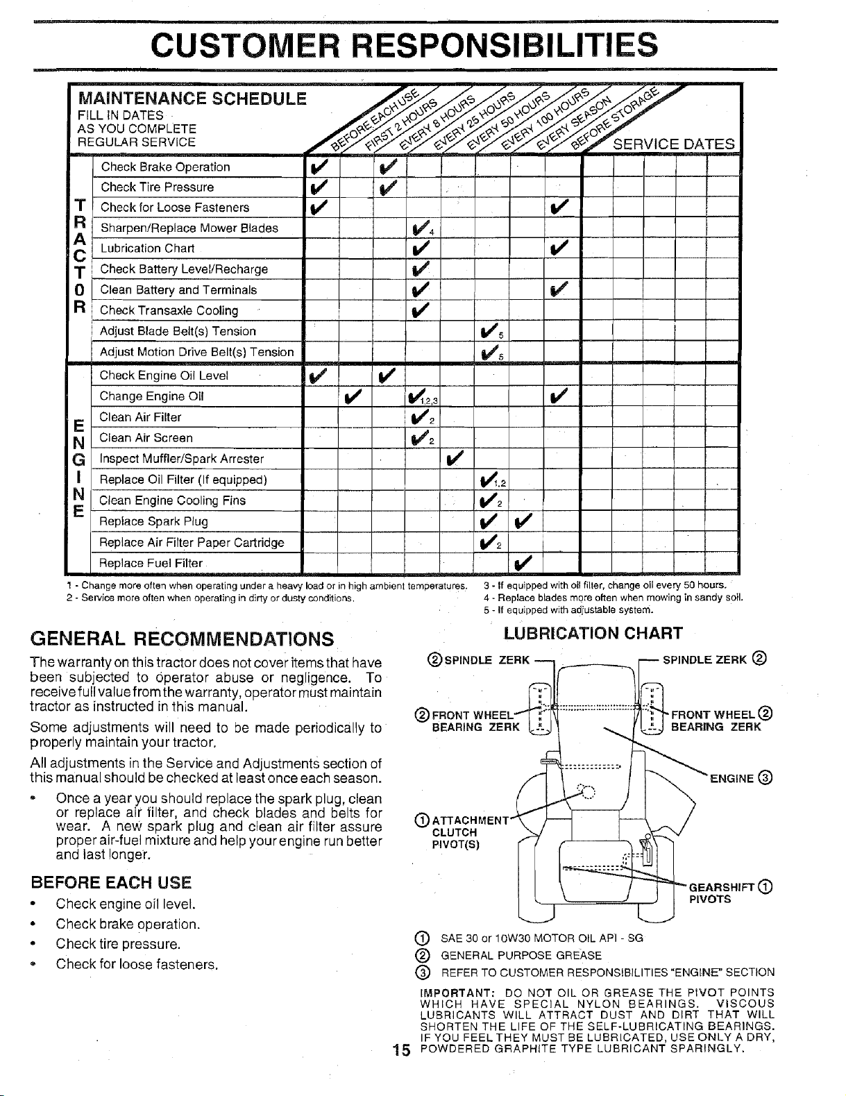
MAINTENANCE SCHEDULE
FiLL iN DATES
AS YOU COMPLETE
REGULAR SERVICE
SERVICE DATES
Check Brake Operation
Check Tire Pressure
T
Check for Loose Fasteners
R
sharpen!Replace Mower Blades
Lubrication Chart _ V'
T Check Battery Level!Recharge I
0 Clean Battery and Terminals
a CheckTransaxle Cooling
Adjust Blade Belt(s)Tension
Adjust Motion Drive Belt(s) Tension
CheckEngine Oil Level
ChangeEngine Oil
Clean Air Filter
E
v' v' ! [
v' v'
N Clean Air Screen
G InspectMuffler/Spark Arrester
Replace Oil Filter (If equipped)
N Clean EngineCooling Fins
ReplaceSpark Plug
ReplaceAir FilterPaper Cartridge
Replace Fuel Filter
1 - Change more often when operating under a heavy load or in high ambient temperatures.
2 - Service more often when operating in dirty or dusty conditions,
GENERAL RECOMMENDATIONS
The warranty on this tractor does not cover items that have
been subjected to Operator abuse or negligence. To
receive full value from the warranty, operator must maintain
tractor as instructed in this manual.
Some adjustments will need to be made periodically to
properly maintain your tractor.
All adjustments in the Service and Adjustments section of
this manual should be checked at least once each season.
Once a year you should replace the spark plug, clean
or replace air filter, and check blades and belts for
wear. A new spark plug and clean air filter assure
proper air-fuel mixture and help yourengine run better
and last longer.
v',
v' v'
v'
V='5
v'
v'2
v'
V_1_2
v'2 !
l¸
3 - If equipped with oil filter, change oil every 50 hours.
4 - Replace blades more often when mowing in sandy soil.
5 - If equipped with adiustable system.
LUBRICATION CHART
(_ SPINDLE ZERK
(_ FRONT
BEARING ZERK
®
CLUTCH
PIVOT(S)
SPINDLE ZERK(_
"FRONT WHEEL(_
BEARING ZERK
®
BEFORE EACH USE
• Check engine oil level.
• Check brake operation.
• Check tire pressure.
* Check for loose fasteners.
_=ARSHIFT O
PIVOTS
(_) SAE 30 or 10W30 MOTOR OIL API -
® GENERAL PURPOSE GREASE
(_) REFER TO CUSTOMER RESPONSIBILITIES"ENGINE'
IMPORTANT: DO NOT OIL OR GREASE THE PIVOT POINTS
WHICH HAVE SPECIAL NYLON BEARINGS. VISCOUS
LUBRICANTS WILL ATTRACT DUST AND DIRT THAT WILL
SHORTEN THE LIFE OF THE SELF-LUBRICATING BEARINGS.
IF YOU FEEL THEY MUST BE LUBRICATED, USE ONLY A DRY,
15 POWDERED GRAPHITE TYPE LUBRICANT SPARINGLY.
SG
SECTION
TRACTOR
CUSTOMER RESPONSIBILITIES
Always observe safety rules when performing any mainte-
nance.
BRAKE OPERATION
If tractor requires more than six (6) feet stopping distance
at high speed in highest gear, then brake must be adjusted.
(See "TO ADJUST BRAKE" in the Service and Adjust-
ments section of this manual).
TIRES
- Maintain proper air pressure in all tires (See "PROD-
UCT SPECIFICATIONS" on page 3 of this manual).
• Keep tires free of gasoline, oil, or insect control chemi-
cals which can harm rubber:
• Avoid stumps, stones, deep ruts, sharp objects and
other hazards that may cause tire damage.
BLADE CARE
For best results mower blades must be kept sharp. Re-
place bent or damaged blades.
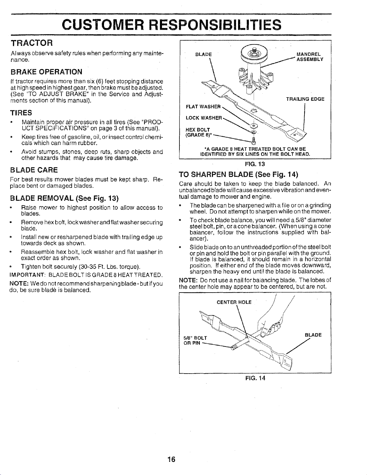
BLADE REMOVAL (See Fig. 13)
, Raise mower to highest position to allow access to
blades.
• Remove hex bolt, Iockwasher and flat washer securing
blade.
• install new or resharpened blade with trailing edge up
towards deck as shown.
, Reassemble hex bolt, lock washer and flat washer in
exact order as shown.
° Tighten bolt securely (30-35 Ft. Lbs. torque).
IMPORTANT: BLADE BOLT IS GRADE 8 HEAT TREATED.
NOTE: We do not recommend sharpening blade- but ifyou
do, be sure blade is balanced.
BLADE
FIG, 13
TO SHARPEN BLADE (See Fig. 14)
Care should be taken to keep the blade balanced. An
unbalanced blade will cause excessive vibration and even-
tual damage to mower and engine.
• The blade can be sharpened with a file or on a grinding
wheel. Do not attempt to sharpen while on the mower.
,, To check blade balance, you will need a 5/8" diameter
steel bolt, pin, or acone balancer. (When using a cone
balancer, follow the instructions supplied with bal-
anCer).
', Slide blade on to an unthreaded portion of the steel bolt
or pin and hold the bolt or pin paraliel with the ground.
If blade is balanced, it should remain in a horizontal
position. If either end of the blade moves downward,
sharpen the heavy end until the blade is balanced.
NOTE: Do not use a nail for balancing blade. The lobes of
the center hole may appear to be centered, but are not.
CENTERHOLE / /
518" BOLT BLADE
OR PIN
FiG. 14
16
CUSTOMER RESPONSIBILITIES
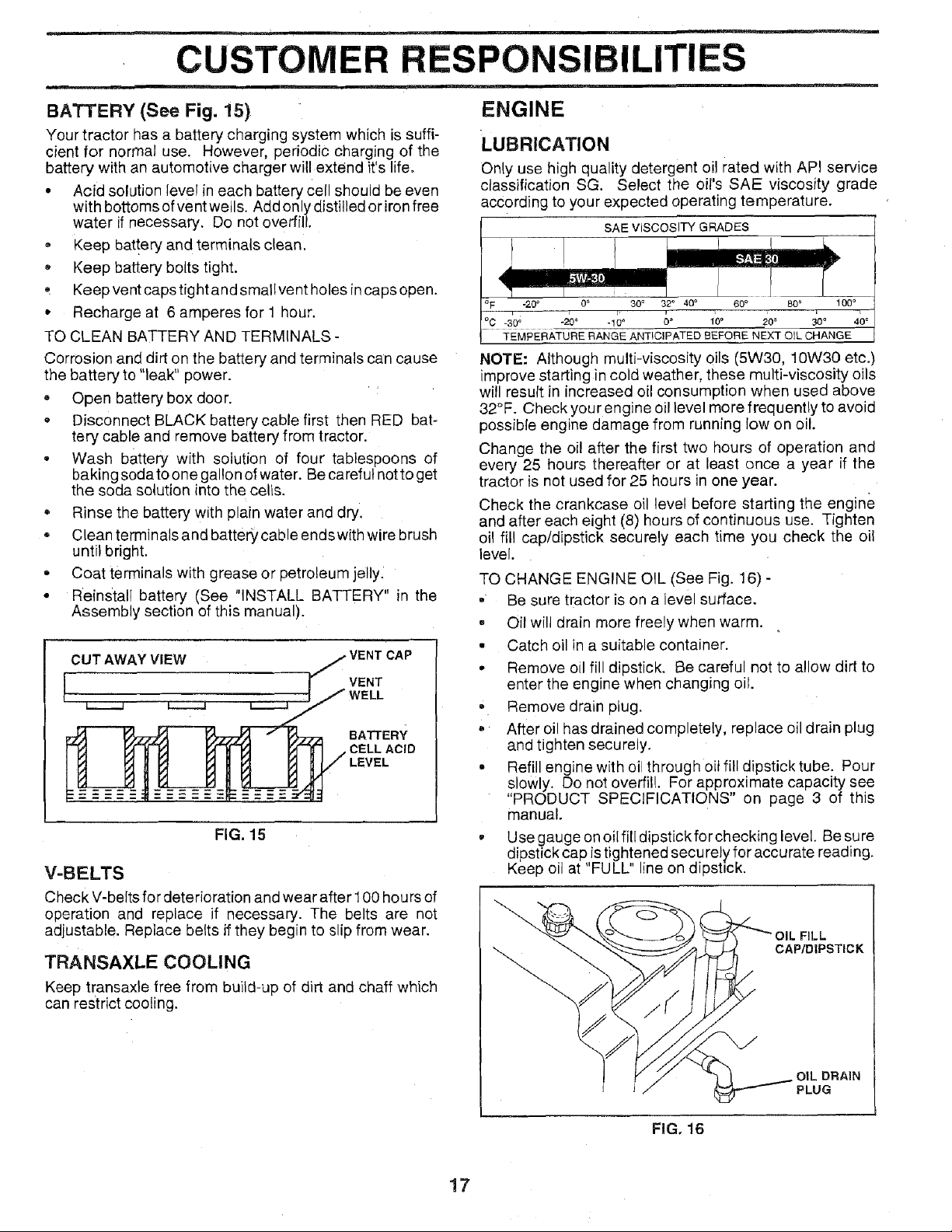
BATTERY (See Fig. 15)
Your tractor has a battery charging system which is suffi-
cient for normal use. However, periodic charging of the
battery with an automotive charger will extend it's life.
• Acid solution level in each battery Cell should be even
with bottoms ofvent wells. Add only distilled or iron free
water if necessary. Do not overfill.
, Keep bat!ery and terminals clean.
• Keep battery bolts tight.
, Keep vent caps tight and smallvent holes in caps open,
• Recharge at 6 amperes for 1 hour.
TO CLEAN BATTERY AND TERMINALS -
Corrosion and dirt on the battery and terminals can cause
the battery to "leak" power.
• Open battery box door.
= Disconnect BLACK battery cable first then RED bat-
tery cable and remove battery from tractor.
• Wash battery with solution of four tablespoons of
baking soda to one gallon of water. Be careful notto get
the soda solution into the cells.
= Rinse the battery with plain water and dry.
Clean terminals and battery cable endswith wire brush
until bright.
= Coat terminals with grease or petroleum jelly.
• Reinstall battery (See "INSTALL BATTERY" in the
Assembly section of this manual).
CUT AWAY VIEW
VENT
BATTERY
CELL ACID
FIG. 15
V-BELTS
Check V-belts for deterioration and wear after 100 hours of
operation and replace if necessary. The belts are not
adjustable. Replace belts ifthey begin to slip from wear.
TRANSAXLE COOLING
Keep transaxle free from build-up of dirt and chaff which
can restrict cooling.
i ii,. i1_
ENGINE
:LUBRICATION
Only use high quality detergent oil rated with API service
classification SG. Select the oil's SAE viscosity grade
according to your expected operating temperature.
SAEVlSCOSlWGRADES
° F -20 _ 0 ° 30 ° 32° 40 ° 60_ 80* 100 °
°C -30; "20° "10 ° 10° 20_ 30° 40°
TEMPERATURE RANGE ANTICIPATED BEFORE NEXT OIL CHANGE
NOTE: Although multi-viscosity oils (5W30, 10W30 etc.)
improve starting in cold weather, these multi-viscosity oils
will result in increased oil consumption when used above
32°F. Check your engine oil level more frequently to avoid
possible engine damage from running low on oil.
Change the oi! after the first two hours of operation and
every 25 hours thereafter or at least once a year if the
tractor is not used for 25 hours in one year.
Check the crankcase oil level before starting the engine
and after each eight (8) hours of continuous use. Tighten
oil fill cap/dipstick securely each time you check the oil
level.
TO CHANGE ENGINE OIL (See Fig. 16) -
• Be sure tractor is on a level surface.
, Oil will drain more freely when warm.
• Catch oil in a suitable container.
• Remove oil fill dipstick. Be careful not to allow dirt to
enter the engine when changing oil.
• Remove drain plug.
• After oil has drained completely, replace oil drain plug
and tighten securely.
. Refill engine with oil through oil fitl dipstick tube. Pour
slowly. Do not overfill. For approximate capacity see
"PRODUCT SPECIFICATIONS" on page 3 of this
manual.
• Use gauge on oil ill[ dipstick for checking level. Be sure
dipstick cap istightened secu rely for accu rate reading.
Keep oil at "FULL" line on dipstick.
FiLL
CAP/DIPSTICK
17
OIL DRAIN
PLUG
FIG. 16
 Loading...