

Craftsman 917254850 Owner’s Manual

®
MODEL NUMBER 917.254850 OWNER'SMANUAL
Assembly
• Operation
• Customer
Responsibilities
oService
oAdjustments
oRepair Parts
Caution:
Read and Follow
all Safety Rules
and Instructions
Before Operating
This Equipment

Safe Operation Practices for Ride-On Mowers
SAFETY RULES
IMPORTANT: THIS CUTTING MACHINE ISCAPABLE OFAMPUTATING HANDS AND FEET AND THROWING OBJECT&
FAILURE TO OBSERVE THE FOLLOWING SAFETY INSTRUCTIONS COULD RESULT IN SERIOUS INJURY OR DEATH.
I. GENERAL OPERATION
• Read, understand, and follow alt instructions in the manuat
and on the machine before starting..
• Onty allow responsible adults, who are familiar with the
instructions, to operate the machine.
• Clear the area of objects such as rocks, toys, wire, etc.
which could be picked up and thrown by the blade.
• Be sure the area is clear of other people before mowing Stop
machine if anyone enters the area.,
° Never carry passengers.
• Do not mow in reverse unless absolutely necessary.. Always
look down and behind before and while backing.
° Be aware of the mower discharge direction and do not point
it at anyone. Do not operate the mower without either the
entire grass catcher or the guard in place_
• Slow down before turning.
• Never leave a running machine unattended. Atways turn off
blades, set parking brake, stop engine, and remove keys
before dismounting
° Turn off blades when not mowing.
° Stop engine before removing grass catcher or unclogging
chute..
• Mow only in daylight or good artificial light
° Do not operate the machine while under the influence of
alcohol or drugs,
• Watch for traffic when operating near or crossing roadways
• Use extra care when loading or unloading the machine into
a trailer or truck.
!1. SLOPE OPERATION
Slopes are a major factor related to toss-of-control and
tipover accidents, which can result in severe injury or death.
AI! slopes require extra caution, tfyou cannot back up the
slope or' if you fee! uneasy on it, do not mow it.
DO:
° Mow up and down slopes, not across_
° Remove obstacles such as rocks, tree limbs, etc
• Watch for hotes, ruts, or bumps. Uneven terrain could
overturn the machine. Tall grass can hide obstacles
• Use slow speed. Choose a low gear so that you will not have
to stop or shift while on the slope.
° Follow the manufacturer's recommendations for wheel
weights or counterweights to improve stability..
° Use extra care with grass catchers or other attachments,
These can change the stability of the machine
° Keep all movement on the slopes sfowand gradual. Do not
make sudden changes in speed or direction.
° Avoid starting or stopping on a slope, tf tires lose traction,
disengage the blades and proceed slowly straight down the
slope
DO NOT:
o Do not turn on slopes unless necessary, and then, turnslowly
and gradually downhill, if possible..
o Do not mow near drop-offs, ditches, or embankments. The
mower could suddenly turn over if a wheel is over the edge
of a cliff or ditch, or if an edge caves in.
° Do not mow on wet grass. Reduced traction could cause
sliding.
• Do not try to stabilize the machine by putting your foot on the
ground.
• Do not use grass catcher on steep slopes..
IlL CHILDREN
Tragic accidents can occur if the operator is not alert to the
presence of children. Children are often attracted to the
machine and the mowing activity. Never' assume that
children will remain where you last saw them.
• Keep children out of the mowing area and under the watchful
care of another responsible adult.
• Be alert and turn machine off if children enter the area.,
° Before and when backing, look behind and down for small
children..
° Never carry children. They may fall off and be seriously
injured or interfere with safe machine operation..
° Never allow children to operate the machine..
° Use extra care when approaching blind corners, shrubs,
trees, or other objects that may obscure vislon_
IV. SERVICE
• Use extra care inhandling gasoline and other fuets_ They are
flammable and vapors are explosive,
Use only an approved container_
Never remove gas cap or add fuel with the engine
running Allow engine to cool before refueling Do not
smoke
Never refuel the machine indoors.
Never store the machine or fuel container inside where
there is an open flame, such as a water heater..
• Never run a machine inside a dosed area_
• Keep nuts and boits, especially blade attachment bolts, tight
and keep equipment in good condition
• Never tamper with safety devices. Check their proper
operation regulady_
• Keep machine free of grass, leaves, or other debris build-up.
Clean oil or fuel spitiage Allow machine to cool before
storing
• Stop and inspect the equipment if you strike an object..
Repair, if necessary, before restarting,
• Never make adjustments or repairs with the engine running_
• Grass catcher components are subject to wear, damage, and
deterioration, which could expose moving parts or allow
objects to be thrown. Frequently check components and
replace with manufacturer's recommended parts, when nec-
essary
• Mower blades are sharp and can cut. Wrap the blade(s) or
wear gloves, and use extra caution when servicing them_
• Check brake operation frequently. Adjust and service as
required.
tant safety precautions. It means CAU-
A, Look for this symbol to point out impor-
TIONI!t BECOME ALERTV, tt YOUR
SAFETY IS INVOLVED.
CAUTION: Always disconnect sparkplug
wire and place wire where it cannot con-
tact spark plug in order to prevent acci-
dental starting when setting up, trans_
porting, adjusting or making repairs,
2

CONGRATULATIONS on your purchase of a Sears
Tractor,, It has been designed, engineered and manu-
factured to give you the best possible dependability and
performance,
Should you experience any problem you cannot easily
remedy, please contact your nearest Sears Service
CentedDepartmento We have competent, well-trained
technicians and the proper tools to service or repair this
uniL
Please read and retain this manual The instructions wilt
enable you to assemble and maintain your unit properly,,
Always observe the "SAFETY RULES",
MODEL
NUMBER 917°254850
SERIAL
NUMBER
DATE OF PURCHASE
THE MODEL AND SERIAL NUMBERS WILL BE FOUND
ON A PLATE UNDER THE SEAT,,
YOU SHOULD RECORD BOTH SERIAL NUMBER AND
DATE OF PURCHASE AND KEEP IN A SAFE PLACE
FOR FUTURE REFERENCE°
MAINTENANCE AGREEMENT
A Sears Maintenance Agreement is available on this prod-
ucto Contact your nearest Sears store for details,,
CUSTOMER RESPONStBILITIES
. Read and observe the safety rules.
° Follow a regularschedule in maintaining, caring for and
using your unit,,
° Follow the instructions under "Customer Responsibili-
ties" and "Storage" sections of this owner's manual.
PRODUCT SPECIF CATIONS
HORSEPOWER: 14
GASOLINE CAPACITY: 5 QUARTS
UNLEADED REGULAR
OIL (35 PINTS W/O FILTER): SAE 30 (Above 32°F)
(4,0 PINTS WlFILTER): SAE 5W-30 (Below 32°F)
SPARK PLUG (GAP030 IN,): CHAMPION RC-12YC
VALVE CLEARANCE: iNTAKE ,,0015 - ,0030 IN.
EXHAUST ,0020- :0035 IN.,
GROUND SPEED: FORWARD
1st 1o10 MPH
2nd 1_40 MPH
3rd 2.00 MPH
4th 3,,00 MPH
5th 4,,20 MPH
6th 5,00 MPH
REVERSE: 1o50 MPH
TIRE PRESSURE: FRONT: 14 PSI
REAR: 12 PSI
CHARGING SYSTEM: 3 AMPS BATTERY
5 AMPS HEADLIGHTS
BLADE BOLT TORQUE: 30-35 FT_LBS,,
WARNING: This unit is equipped with an internal combus-
tion engine and should not be used on or near any unim-
proved forest-covered, brush-covered or grass-covered
rand unless the engine's exhaust system is equipped with
a sp.ark arrester meeting applicable local or state laws {if
any),, ITa spark arres_er Jsusea, i[ snould be maimainea _n
effective working order by the operator.,
In the state of California the above is required by law
(Section 4442 of the California Public Resources Code).
Other states may have similar laws,, Federal laws apply on
federal lands, A spark arrester for the muffler is available
through your nearest Sears Authorized Service Center
(See REPAIR PARTS section of this manua0.
iiii / iin ............................ ,.............. :,
Lt /ilTED TWO YEAR WARRANTY ON ELECTRIC START RIDING EQUIPMENT
For two (2) years from the date of purchase, if this riding equipment is maintained, lubricated and tuned up according to the
instructions in the owner's manual, Sears will repair or replace, free of charge, any parts found to be defective in material or
workmanship,,
This Warranty does not cover:
* Expendable items which become worn during normal use, such as blades, spark pEugs,air cleaners and belts°
- Tire replacement or repair caused by punctures from outside objects, such as nails, thorns, stumps, or gJass,,
. Repairs necessary because of operator abuse, negligence, improper storage or accident or the failure to maintain the
equipment according to the instructions contained in the owner's manual
. Riding equipment used for commercial or rental purposes.
LIMITED 90 DAY WARRANTY ON BATTERY
For 90 days from date of purchase, if any battery inctuded with this riding equipment proves defective in material or workmanship
and our testing determines the battery will not hold a charge, Sears will replace the battery at no charge.
WARRANTY SERVICE IS AVAILABLE BY RETURNING THE RIDING EQUIPMENT TO THE NEAREST SEARS SERVICE
CENTER/DEPARTMENT IN THE UNITED STATES,
This Warranty gives you specific legal rights, and you may also have other rights which may vary from state to state
SEARS, ROEBUCK AND CO,,, D/817 WA, HOFFMAN ESTATES, ILLINOIS 60179
......................................................... hi, i i ' ::: ........... ::: i,,,i
3

TABLE OF
CONTENTS
SAFETY RULES ............................................................ 2
PRODUCT SPECIFICATIONS ...................................... 3
CUSTOMER RESPONSIBILITIES ..................... 3, 15-19
WARRANTY .................................................................. 3
TABLE OF CONTENTS ................................................ 4
INDEX ..................................................... ;...................... 4
TRACTOR ACCESSORIES .......................................... 5
ASSEMBLY .............................................................. 7-10
itNDEX
A
Accessories .................................................................5
Adjustments:
Brake .........................................................22
Carburetor, ......................................................25
Mower
Front-To-Back ......................................21
Side-To-Side ................................21
"l"hrottle Control Cable .........................25
Air Filter, Engine .............................................18
Air Screen, Engine .........................................18
Assembly ...........................................................7-10
B
Battery:
Charging .......................................................8
Cleaning .........................................................17
installation ........................................................9
Levels .................................................8,17
Preparation .................................................8
Starting with Weak Battery ............23
Storage ..........................................................26
Terminals .....................................................17
Belt:
Motion Drive
Removal/Replacement ................22
Mower Blade Drive
Removal/Replacement ...............22
Blade:
Sharpening ..................................................16
Replacement .............................................16
Brake Adjustment ...........................................22
C
CarburetorAdjustment ................................25
Controls, Tractor ..............................................11
Customer Responsibilities ..................15-19
Engine:
Air Filter .............................................18
Air Screen, Engine ...........................18
Battery .................................................17
Cooling Fins, Engine ......................18
Engine Oil ..............................................17
Fuel Filter ...........................................19
Spark Plugs .........................................19
Tractor:
Blade ..........................................................16
Lubrication Chart ...............................15
Maintenance Schedule ..................15
Tire Care .......................................8,16,23
Cutting Height, Mower .............................12
Electrical:
Interlocks and Relays ...........................24
Schematic ...............................................29
Widng Diagram ....................................30
Engine:
Air Filter .......................................................t8
Air Screen .................................................18
Cooling Fins, Engine ..........................18
Oil Change ..............................................17
Oi! Level ...............................................13,17
Oil Type .....................................................17
Preparation ..................................................13
Repair Parts .....................................48-53
Starling .......................................................14
Storage ......................................................26
Filter:
Air Filter ....................................................18
Fuel ..............................................................19
Fuel:
Type ............................................................13
Storage ........................................................26
Fuse .......................................................................24
Hood Removal/Installation .................24
Leveling Mower Deck ................................21
Lubrication:
Chart .........................................................15
Maintenance Schedule .................................15
Mower:
Adjustment, Front-to-Back .............21
Adjustment, Side-to-Side .................21
Blade'Sharpening ..............................16
Blade Replacement ................................16
Cutting Height ........................................12
Installation .................................................20
Operation .....................................................13
Removal ...............................................20
Mowing Tips ..................................................14
Muffler, ..................................................................19
Spark Arrester .................................3,40
Mulcher Plate ...........................................10
Oil:
Cold Weather Conditions ...........13,17
Engine .................................................17
Storage ........................................................26
OPERATION .......................................................... :I1.14
MAINTENANCE SCHEDULE ...................................... 15
SERVICE AND ADJUSTMENTS ............................ 20-25
STORAGE ................................................................... 26
TROUBLESHOOTING ........................................... 27-28
REPAIR PARTS - TRACTOR ................................ 30-47
REPAIR PARTS - ENGINE .................................... 48-53
PARTS ORDERING/SERVICE .................. BACK PAGE
E
Operation .....................................................1!-14
Operating Mower .............................................13
Options:
Accessories ..................................................5
Spark Arrester. ..................................3,40
P
Parking Brake .........................................11-12
Parts Bag ....................................................................6
Parts, Replacement/Repair ...............30-47
Product Specifications .........................................3
R
Repair Parts ....................................................30-47
S
F
H
L
M
Safety Rules ..................................................................2
Seat ......................................................................8
Service and Adjustments .......................20-25
Carburetor ....................................................25
Fuse .............................................................. 24
Hood Removal/InstaUation ................23
Motion Ddve Belt
Removal/Replacement ................22
Mower Blade Drive Belt
RemovaltReplacement .................22
Mower Adjustment
Front- to-Back ..............................2!
Side-to-Side ....................................21
Mower Removal ....................................20
Tire Care ..........................................8,16,23
Slope Guide Sheet ......................................55
Spark Plugs .......................................................19
Specifications ..............................................................3
Starting the Engine ..............................13-14
Steering Wheel .............................................7,23
Stopping the Tractor ....................................12
Storage ...................................................................26
T
Throttle Control Cable
Adjustment ................................................25
Tires .......................................................................8,16,23
Trouble Shooting Chart .......................27-28
Transaxle:
Repair Parts ........................................46-47
O
Warranty .................................................................3
WMng Diagram ....................................................30
Wiring Schematic ..................................................29
W
4
ACCESSO
-.......... .................. ....... ,i,,,i ,,11.... 1_ ..............
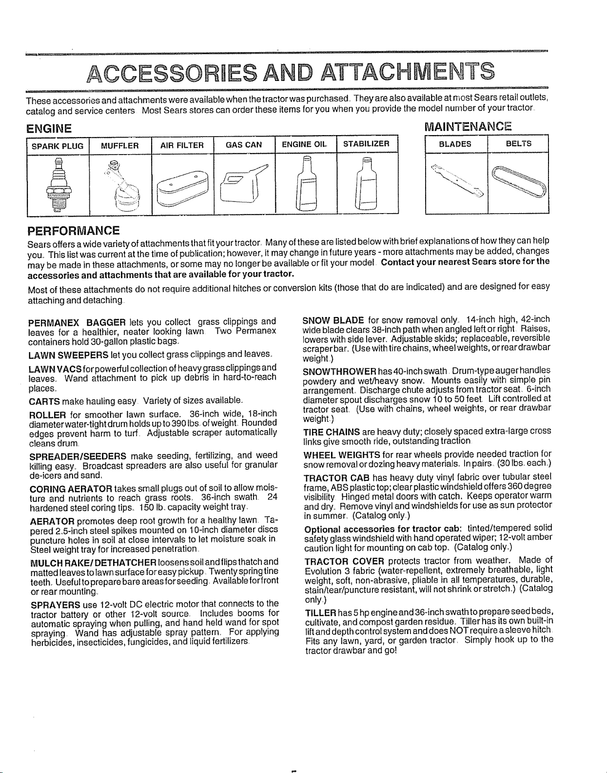
These accessories and attachments were available when the tractor was purchased They are also available at most Sears retail outlets,
catalog and service centers Most Sears stores can order these items for you when you provide the model number of your tractor
BESA
ATTACHMENTS
ENGINE MAINTENANCE
_ARKPLUG
MUFFLER AIR FILTER
........ r ........
GAS CAN ENGINE OIL
STABILIZER
, ,,,,, .....
BLADES
BELTS
Ft.
PERFORMANCE
Sears offers a wide variety of attachments that fit your tractor, Many of these are listed below with brief explanations of how they can help
you This list was current at the time of publication; however, it may change infuture years - more attachments may be added, changes
may be made in these attachments, or some may no longer be available or fit your model Contact your nearest Sears store for the
accessories and attachments that are available for your tractor.
Most of these attachments do net require additional hitches or conversion kits (those that do are indicated) and are designed for easy
attaching and detaching
PERMANEX BAGGER lets you collect grass clippings and
leaves for a healthier, heater looking lawn Two Permanex
containers hold 30-gallon plastic bags.
LAWN SWEEPERS let you collect grass clippings and leaves
LAWN VACS for powerful collection of heavy grass clippings and
leaves Wand attachment to pick up debris in hard4o-reach
places
CARTS make hauling easy Variety of sizes available.
ROLLER for smoother lawn surface. 36-inch wide, 18-inch
diameterwater4ight drum hotds up to 390 fbs of weight Rounded
edges prevent harm to turf Adjustable scraper automatically
cleans drum
SPREADERISEEDERS make seeding, fertilizing, and weed
killing easy Broadcast spreaders are also usefut for granular
de-icers and sand,
CORING AERATOR takes small plugs out of soil to allow mois-
ture and nutrients to reach grass roots 364nch swath 24
hardened steel coring tips_ 150 Ib capacity weight tray.
AERATOR promotes deep root growth for a healthy lawn Ta-
pered 2,5-inch steel spikes mounted on 10-inch diameter discs
puncture holes in soil at close intervals to let moisture soak in
Steel weight tray for increased penetration
MULCH RAKE/DETHATCH ER loosens soil and flips thatch and
matted leaves to lawn surface for easy pickup Twenty spring tine
teeth. Useful to prepare bare areas ferseeding Available forfrent
or rear mounting
SPRAYERS use 12-volt DC electric motor that connects to the
tractor battery or other 12-volt source, includes booms for
automatic spraying when pulling, and hand held wand for spot
spraying Wand has adjustable spray pattern For applying
herbicides, insecticides, fungicides, and liquid fertilizers
SNOW BLADE for snow removal only 144nch high, 42-inch
wide blade clears 38-inch path when angled left or right Raises,
lowers with side lever, Adjustable skids; replaceable, reversible
scraper bar. (Use with tire chains, wheelweights, or rear drawbar
weight.)
SNOWTHROWER has40-inchswath Drum4ypeaugerhandles
powdery and wet/heavy snow. Mounts easily with simple pin
arrangement, Discharge chute adjusts from tractor seat 6-inch
diameter spout discharges snow 10 to 50 feet Lift controlled at
tractor seat (Use with chains, wheel weights, or rear drawbar
weight.)
TIRE CHAINS are heavy duty; closely spaced extra-large cross
links give smooth ride, outstanding traction
WHEEL WEIGHTS for rear wheels provide needed traction for
snow removal or dozing heavy materials° in pairs (30 lbs, each,)
TRACTOR CAB has heavy duty vinyl fabric over tubular steel
frame, ABS plastic top; clear plastic windshietd offers 360 degree
visibility Hinged metal doors with catch. Keeps operator warm
and dry Remove vinyl and windshields for use as sun protector
in summer (Catalog only,)
Optional accessories for tractor cab: tinted/tempered solid
safety glass windshield with hand operated wiper; 12-volt amber
caution light for mounting on cab top. (Catalog only..)
TRACTOR COVER protects tractor from weather. Made of
Evolution 3 fabric (water-repellent, extremely breathable, light
weight, soft, non-abrasive, pliable in all temperatures, durable,
stain/teadpuncture resistant, will not shrink or stretch,.) (Catalog
only)
TILLER has 5 hp engine and 36-inch swath to prepare seed beds,
cultivate, and compost garden residue, Tiller has its own built-in
lift and depth control system and does NOT require asleeve hitch
Fits any lawn, yard, or garden tractor Simply hook up to the
tractor drawbar and go!

CONTENTS OF HARDWARE PACK
............ i .... i.... II'_lL'L'l''1
Parts Bag contents shown full size
= .............. ,,,, ......._......... ..r, ........... ,....
Parts packed separately in carton
(2) Sheet
Metal
©
(1) Shoulder Bolt 5/16-18 (1) Hex Bolt 1/2-13 x !
Screws
#10-16 x 1/2
@
(1) Lock Washer 1/2
(!) Washer' 17/32x 1-3/16 x i2 Gauge
Seat
Battery acid
Mulcher
Plate
Steering
Wheel
Steering
Boot
Owner's Manual Parts Bag
......... iHll i,, i, i......................................
Parts bag contents not shown full size
©
(2) Shoutder (2) Locknuts
Bolts 3/8-16
(2) Screws #10 x 5/8 (2) Lock Washers #10
(2) Weld Nuts #10 _ I
(2) Washers 3/16 x 3/4 x 16 Gauge
LJ
..................
(2) Hex Bolts 1/4-20 x 3/4
(2) Hex Nuts 1/4-20
(2) Washers 9/32 x 5/8 x 16 Gauge
(2) Lock Washers 1/4
Steering
,Wheel Steering Wheel
Insert Adapter
_(2) Latch Ho-__ok
Assemblies
! i' 1
15° Slope Sheet
_ teering
(2) Keys
(2) GaugeWheels
Bushing
J
i
Battery Caps
and Instructions

ASSEM LY
Your new tractor has been assembled at the factory with exception of those parts left unassembled for shipping purposes.
To ensure safe and proper operation of your tractor all parts and hardware you assemble must be tightened securely., Use
the correct tools as necessary to insure their proper tightness.
TOOLS REQUIRED FOR ASSEMBLY
A socket wrench set will make assembly easien Standard
wrench sizes are listed°
(1) 5/16" wrench
(2) 7/16" wrenches
(1) 9/16" wrench
(1) 3/4" socket & drive ratchet
Tire pressure gauge
Phillips Screwdriver
WHEEL
Utility knife
(1) i/2" wrench
When right and left hand is mentioned in this manual, it
means when you are in the operating position (seated
behind the steering wheel),
TO REMOVE UNIT FROIVi CARTON
UNPACK CARTON
o Remove alt accessible loose parts and parts cartons
from carton (See page 6).
o Cut along lines on carton, from top to bottom, all four
corners of carton and lay panels flat.
• Check for any additional loose parts or cartons and
remove..
BEFORE ROLLING UNIT OFF SKID
ATTACH STEERING WHEEL (See Fig. 1)
, Slide the steering bushing over the steering shaft.
o Raise steering shaft forward until screw holes in dash
line up with steering bushing. Install two (2) sheet
metal screws and tighten securely°
= Position steering boot over steering shaft.
° Align tabs of steering boot over slots and hole in dash
and push down to secure.
° Slide steering wheel adapter onto upper steering shaft°
. Position front wheels of the tractor so they are pointing
straight forward.
o Position steering wheel so cross bars are horizontal
(left to right) and slide onto adapter,,
o Assemble large flat washer and 3/8-24 hex locknut and
tighten securely,
° Snap insert into center of steering wheel.
o Remove protective plastic from tractor hood and grill,
IMPORTANT: CHECK FOR AND REMOVE ANY
STAPLES IN SKiD THAT MAY PUNCTURE Tl RESWHERE
UNIT iS TO ROLL OFF SKID,
STEERING
ADAPTER
WHEEL "__
STEERING ,__ABS,
SHAFT
(ASSEMBLY TAB
POSITION)
/
/
STEERIN ..... "_-. , ,
SHAFT .... ' '
(SHIPPING
POSITION)
=
STEERING
BUS}
SCREW
SLOT
FIG. 1
TO ROLL UNIT OFF SKiD (See Fig. 8)
- Raise attachment lift lever to its highest position,,
° Release parking brake by depressing clutchtbrake
pedal.
o Place gearshift lever in "NEUTRAL" position.
, Roll unit backwards off skid,
- Remove banding holding discharge guard up against
tracton

:=: _: : i ..... i .. i. . ill.. ............ii iill...lll,, i ,.I.IHlll .m.
HOW TO SET UP YOUR TRACTOR
PREPARE BATTERY (See Fig. 2)
CAUTION: Wear eye and face shield.
Wash hands or clothing immediately if
accidentally incontact with battery acid,
Do not smoke. Fumes from charged
battery acid are explosive. Read the
instructions included with the battery
vent caps. Always wear gloves, cloth-
ing and goggles to protect your' hands,
skin and eyes.
Your unit has a battery charging system which is sufficient
for normal use_ However', periodic charging of the battery
with an automotive charger will extend its life
*" See instructions packed with vent caps in parts bag..
= Fill battery with acid_ Fill each cell until it reaches the
bottom of the vent wells._ Do not overfill
Allow battery to stand and settle for at least thirty
minutes.. After standing, check the level of acid_ if
below the vent wells, add more acid until the correct
level is reached.
While battery isstanding (after adding acid) and later, while
battery is being charged, continue with assembly of uniL
IMPORTANT: TO MAXIMIZE THE LIFE OF YOUR
BATTERY, IT tS NECESSARY THAT THE BATTERY BE
CHARGED BEFORE USE. FAILURE TO CHARGE
BATTERY CAN RESULT IN A SHORTENED BATTERY
LIFE,
o Charge battery at a rate of 6 amperes for i hour. Use
a 12 volt battery charger,. Observe all safety precau-
tions required for' battery charging.
, Check the acid level after' the battery is charged. If the
acid has fallen below the correct level, add distilled or
iron free water,
o Install the vent caps to cover the vent wells, Wash the
top of the battery with water to remove any acid, then
wipe dry.
o Check battery case for leakage to make sure that no
damage has occurred in handling,.
° Dispose of excess battery acid. Neutralize acid for
disposal by adding it to four inches of water in a five
gallon plastic container. Stir with a wooden or plastic
paddle while adding baking soda unti! the addition of
more soda causes no more foaming.
° Follow instructions on how to install battery..
LY
INSTALL SEAT (See Fig. 3)
Adjust seat before tightening adjustment bolt.
= Remove cardboard packing on seat pan.
= Place seat on pan and assemble shoulder' bolt.,
o Assemble adjustment bolt, iockwasherandflatwasher
loosely, Do not tighten.
o Tighten shoulder bolt securely..
• Lower seat into operating position and sit on seal
= Slide seat until a comfortable position is reached which
allows you to press clutch/brake pedal all the way down
(See Fig. 8).
o Get off seat without moving its adjusted position,.
o Raise seat and tighten adjustment bolt securety_
SEAT
SEAT PAN
SHOULDER
BOLT
FLAT WASHER
ADJUSTMENT
BOLT
CHECK TIRE PRESSURE
The tires on your unit were overinflated at the factory for
shipping purposes, Correct tire pressure is important for
best cutting performance°
o Reduce tire pressure to PSI shown in "PRODUCT
SPECIFICATIONS" on page 3 of this manual.
CHECK DECK LEVELNESS
Forbest cutting results, mower housing should be properly
leveled. See "TO LEVEL MOWER HOUSING" in the
Service and Adjustments section of this manual
LOCK WASHER
FIG. 3
CUT AWAY VIEW
FIG. 2
VENT WELL
C VENT CAP
BATTERY
CELL ACID
LEVEL
CHECK FOR PROPER POSITION OF ALL BELTS
See the figures that are shown for replacing motion and
mower blade drive belts in the Service and Adjustments
section of this manual Verify that the belts are routed
correctly.
CHECK BRAKE SYSTEM
After you learn how to operate your tractor, check to see
that the brake is properly adjusted° See "TO ADJUST
BRAKE" in the Service and Adjustments section of this

ASSEMBLY
iNSTALL BATTERY (See Figs. 4 & 5)
CAUTION: Do not short battery termi-
nals. Before installing battery, remove
metal bracelets, wristwatch bands,
rings, etc.
Positive terminal must be connected
first to prevent sparking from acciden-
tal grounding.
o Lift seat to raised position
° Open battery box door°
• Lower battery into battery box with battery terminals
toward front of unit
° Be sure battery drain tube is attached to battery box
o First connect RED battery cable to positive (+) battery
terminal with hex bolt, flat washer, tock washer and hex
nut as shown Tighten securely
o Connect BLACK grounding cable to negative (-) bat-
tery terminal with remaining hex bolt, flat washer, lock
washer and hex nut° Tighten securely°
o Close battery box door_
Open battery box door for:
o inspection for secure connections (to tighten hard_
ware)°
o inspection for corrosion
o Testing battery°
o Jumping (if required).,
• Periodic charging _
BATTERY
BOX DOOR
BATTERY
BOX DOOR
VENT CAPS
FIG. 5
ASSEMBLE GAUGE WHEELS TO MOWER
DECK (See Fig.6)
Assemble gauge wheels with tractor on a flat level surface°
- Adjust mower to desired cutting height (See "TO AD-
JUST MOWER CUTTING HEIGHT" in the Operation
section of this manual)
. With mower in desired height of cut position, gauge
wheels should be assembled so they are slightly off the
ground Install gauge wheel in appropriate hole with
shoulder bolt and !ocknut and tighten securely
o Repeat for opposite side installing gauge wheel in
same adjustment hole
POSITIVE NEGATIVE
(RED) CABLE (BLACK) CABLE
POSITIVE (+) TERMINAL
NEGATIVE (-) TERMINAL
BOLT
FIG. 4
3/8-16
LOCKNUT_
GAUGE WHEEL--
__.._ SHOULDER BOLT
FIG. 6

ASSEMBLY
INSTALL IVlULCHER PLATE (See Figs. 7A &
7B)
o Install two latch hooks, to mulcher plate using screw,
washer, lock washer, and weld nut as shown
NOTE: Pre-assemble weld nut to latch hook by insert-
ing weld nut from the top with hook pointing down°
o Tighten hardware securely
o Raise and hold deflector shield in upright position
° Place front of mulcher plate over front of mower deck
opening and slide into place, as shown
° Hook front latch into hole on front of mower deck
o Hook rear latch into hole on back of mower deck.
t_, CAUTION: Do not remove discharge I
guard from mower. Raiseand hold guard I
e_&j_ when attaching mulcher plate and allow
it to rest on plate while in operation. I
WELD NUT HOOK POINTS
FROM THE TOP
WELD
HOOK
MULCHER
PLATE
LOCK
WASHER
_SCREW
FIG, 7A
WASHER
LATCH
HOOK
LOCK
WASHER
WELD
NUT
TO CONVERT TO BAGGING OR DISCHARG-
ING
Simply remove mulcher plate and store in a safe place.
Your mower is now ready for discharging or installation of
optional grass catcher accessory
vrCHECKL IS T
BEFORE YOU OPERATE AND ENJOY YOUR NEW
TRACTOR, WE WISH TO ASSURE THAT YOU RECEIVE
THE BESTPERFORMANCEAND SATISFACTION FROM
THIS QUALITY PRODUCT
PLEASE REVIEW THE FOLLOW!IVG CHECKLIST:
,/ All assembly instructions have beer] completed
v" No remaining loose parts in carton
J Batteryis properly prepared and charged (Minimum
1 hour at 6 amps)
,I Seat is adjusted comfortably and tightened securely_
,." All tires are properly inflated (For shipping purposes,
the tires were overinflated at the factory)
v" Be sure mower deck is properly leveled side-to-side/
front-to-rear for best cutting resultso (Tires must be
properly inflatedfor leveling).
,/ Check mower and drive belts Be sure they are routed
properly around pulleys and inside all belt keepers°
,t" Check wiring. See that all connections are still secure
and wires are properly clamped
WHILE LEARNING HOW TO USE YOUR TRACTOR, PAY
EXTRAA TTENTION TO THE FOLLOWING IMPORTANT
ITEMS:
v' Engine oil is at proper level
,/ Fuel tank is filled with fresh, clean, regular unleaded
gasoline
v' Become familiar with all controls - their location and
function_ Operate them before you start the engine.
,/ Be sure brake system is in safe operating condition.
DEFLECTOR
SHIELD
LATCH
HOOKS
FIG. 7B

KNOW YOUR TRACTOR
READ THiS OWNER'S MANUAL AND SAFETY RULES BEFORE OPERATING YOUR TRACTOR
Comparethe illustrationswithyour tractorto familiarize yourself with the locations of variouscontrolsand adjustmentso Save
this manual for future reference°
ATTACHMENT CLUTCH LEVER
LIFT LEVER
PLUNGER
LIGHT SWITCH
THROTTLE!CHOKE
CONTROL
CLUTCHIBRAKE
PEDAL
HEIGHT ADJUSTMENT
KNOB
Sears tractors conform to the safety standards of the American National Standards Institute,,
ATTACHMENT
LIFT LEVER
GEARSHIFT
LEVER
IGNITION
PARKING BRAKE SWITCH
FIG. 8
ATTACHMENT CLUTCH LEVER: Used to engage the
mower blades, or other attachments mounted to your
tractor.
LIGHT SWITCH: Turns the headlights on and off°
THROTTLE/CHOKE CONTROL: Used for starting and
controlling engine speed.
CLUTCH!BRAKE PEDAL: Used for declutching and brak-
ing the tractor and starting the engine°
PARKING BRAKE: Locks clutch/brake pedal into the
brake position°
GEARSHIFT LEVER: Selects the speed and direction of
tractor.
ATTACHMENT LIFT LEVER: Used to raise and lower the
mower deck or other attachments mounted to your tractor.
LIFT LEVER PLUNGER: Used to release attachment lift
lever when changing its position.
IGNITION SWITCH: Used for starting and stopping the
engine.,
HEIGHT ADJUSTMENT KNOB: Usedto adjust the mower
cutting height°
't'1

The operation of any tractor can result in fo reign objects thrown into the eyes, which can result
in severe eye damage. Always wear safety glasses or eye shields while operating your tractor
or performing any adjustments or repairs. We recommend wide vision safety mask for over
the spectacles or standard safety glasses, available at Sears Retail or Catalog stores..
HOW TO USE YOUR TRACTOR
TO SET PARKING BRAKE (See Fig. 9)
Your unit is equipped with an operator presence sensing
switch,. When engine isrunning, any attempt by the
operator to leave the seat without first setting the parking
brake will shut of the engine,.
o Depress clutch/brake pedal into full "BRAKE" position
and holdo
Place parking brake lever in "ENGAGED" position and
release pressurefrom clutch!brake pedal° Pedal should
remain in "BRAKE" position. Make sure parking brake
will hold vehicle secure.
STOPPING (See Fig. 9)
MOWER BLADES -
* Move attachment clutch lever to "DISENGAGED" po-
sition.
GROUND DRIVE-
• Depress clutch/brake pedal into fuII"BRAKE" position.
° Move gearshift lever to "NEUTRAL" positiOn.
ENGINE -
o Move throttle control to "SLOW"position.
NOTE: Failure to move throttle control to "SLOW" position
and allowing engine to idle before stopping may cause
engine to "bacldire"_
, Turn ignition key to "OFF" position and remove key.
Always remove key when leaving vehicle to prevent
unauthorized use°
o Neveruse choke to stop engine.
NOTE: Undercertain conditions when unit is standing idle
with the engine running, hot engine exhaust gasses may
cause "browning" of grass,, To eliminate this possibility,
always stop engine when stopping unit on grass areas.
CAUTION: Always stop unit completely,
as described above, before leaving the
operator's position; to empty grass
catcher, etc.
TO USE THROTTLE CONTROL (See Fig. 9)
Always operate engine at full throttle,,
. Operating engine at less than full throttle reduces the
battery charging rate..
° Full throttle offers the best bagging and mower perfor-
mance_
TO MOVE FORWARD AND BACKWARD
(See Fig. 9)
The direction and speed of movement is controlled by the
gearshift lever.
, Start tractor with clutch/brake pedal depressed and
gearshift lever in "NEUTRAL" position.
, Move gearshift leverto desired position..
, Slowly release clutch/brake pedal to start movement.
IMPORTANT: BRING TRACTOR TOA COMPLETE STOP
BEFORE SHIFTING OR CHANGING GEARS. FAILURE
TO DO SO WILL SHORTEN THE USEFUL LIFE OF YOUR
TRANSAXLE
ATTACHMENT
CLUTCH LEVER
"ENGAGED"
THROTTLE/CHOKE
CONTROL
CLUTCH/BRAKE PEDAL
"DRIVE" POSITION
HEIGHT ADJUSTMENT KNOB
TO ADJUST MOWER CUTTHNG HEIGHT
(See Fig. 9)
The cutting height is controlled by turning the height adjust-
ment knob in desired direction.
o Turn knob clockwise (f1) to raise cutting height.
, Turn knob counterclockwise (K"_) to lower cutting
heighL
The cutting height range is approximately 1-1/2" to 4". The
heights are measured from the ground to the blade tip with
the engine not running_ These heights are approximate
and may vary depending upon soil conditions, height of
grass and types of grass being mowed°
o The average lawn should be cut to approximately 2_1/2
inches during the cool season and to over 3 inches
dudng hot month& For healthier and better looking
lawns, mow often and after moderate growth.
• For best cutting performance, grass over 6 inches in
t'3
height_should be njowed !wice.L: Matje ,the first cut
POSITION
RKING BRAKE
'ENGAGED" POSITION
GEARSHIFT
LEVER
"DISENGAGE!
POSITION
FIG. 9
OPERATUON
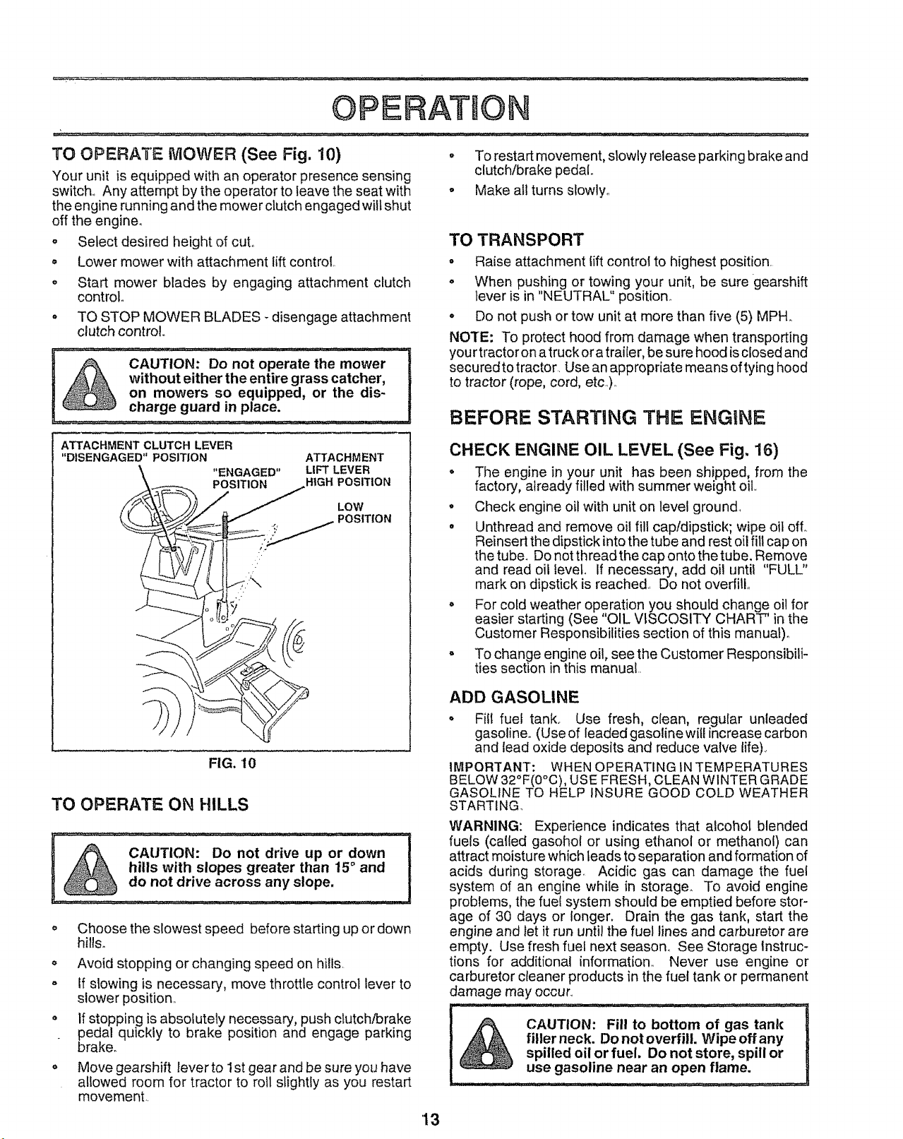
TO OPERATE MOWER (See Fig. 10)
Your unit is equipped with an operator presence sensing
switch° Any attempt by the operator to leave the seat with
the engine running and the mower clutch engaged wilt shut
off the engine.
o Select desired height of cuL
° Lower mower with attachment lift control.
o Start mower blades by engaging attachment clutch
control
o TO STOP MOWER BLADES - disengage attachment
clutch control.,
CAUTION: Do not operate the mower
without either the entire grass catcher,
on mowers so equipped, or the dis-
charge guard in place.
ATTACHMENT CLUTCH LEVER
"DISENGAGED" POSITION
"ENGAGED"
POSITION
ATTACHMENT
LIFT LEVER
HIGH POSITION
LOW
POSITION
° To restart movement, slowly release parking brake and
clutch/brake pedal..
o Make all turns slowly..
TO TRANSPORT
o Raise attachment lift control to highest position.
o When pushing or towing your unit, be sure gearshift
lever is in "NEUTRAL" position.
° Do not push or tow unit at more than five (5) MPH..
NOTE: To protect hood from damage when transporting
your tractor on a truck ora trailer, be sure hood isclosed and
secured to tractor. Use an appropriate means of tying hood
to tractor (rope, cord, etc..).
BEFORE STARTING THE ENGINE
CHECK ENGINE OIL LEVEL (See Fig, 16)
o The engine in your unit has been shipped, from the
factory, already filled with summer weight oil..
° Check engine oil with unit on level ground.
• Unthread and remove oil fill cap/dipstick; wipe oil off..
Reinsert the dipstick into the tube and rest oil fill cap on
the tube. Do not thread the cap onto the tube. Remove
and read oif level If necessary, add oil until "FULL"
mark on dipstick is reached. Do not overfill..
• For cold weather operation you should change oil for
easier starting (See "OIL VISCOSITY CHART" in the
Customer Responsibilities section of this manual).
° To change engine oil seethe Customer Responsibili-
ties section in this manual.
FIG. I0
TO OPERATE ON HILLS
CAUTION: Do not drive up or down
hills with slopes greater than 15 and
do not drive across any slope,
Choose the slowest speed before starting up or down
hills.
o Avoid stopping or changing speed on hills.
o If slowing is necessary, move throttle control lever to
slower position_
= If stopping is absolutely necessary, push clutch/brake
pedal quickly to brake position and engage parking
brake.
Move gearshift lever to 1st gear and be sure you have
allowed room for tractor to roll slightly as you restart
movement..
ADD GASOLINE
° Fill fuel tank.. Use fresh, clean, regular unleaded
gasoline. (Use of leaded gasoline will increase carbon
and lead oxide deposits and reduce valve life)..
IMPORTANT: WHEN OPERATING tNTEMPERATURES
BELOW 32°F(0°C), USE FRESH, CLEAN WINTER GRADE
GASOLINE TO HELP INSURE GOOD COLD WEATHER
STARTING
WARNING: Experience indicates that alcohol blended
fuels (cal{ed gasohol or using ethanol or methanol) can
attract moisture which leads to separation and formation of
acids during storage. Acidic gas can damage the fuel
system of an engine whiie in storage. To avoid engine
problems, the fuel system should be emptied before stor-
age of 30 days or longer. Drain the gas tank, start the
engine and let it run until the fuel lines and carburetor are
empty. Use fresh fuel next season° See Storage instruc-
tions for additional information.. Never use engine or
carburetor cieaner products in the fuel tank or permanent
damage may occur
filler neck. Do not overfill Wipe offany
CAUTION: Fill to bottom of gas tank
spilled oil or fuel, Do not store, spill or
use gasoline near an open flame.
'13

OPERATI ON
TO START ENGINE (See Fig. 9)
When starting engine for the first time or if engine has run
out of fuel, itwilltake extra cranking time to move fuel from
the tank to the engine.
• Depress the clutch/brake pedal and set the parking
brake.
° Place gearshift lever' in "NEUTRAL" position.
, Move attachment clutch to "DISENGAGED" position.
o Move throttle control lever' to "CHOKE" position for
cold engine start_ For warm engine start, move throttle
control to "FAST" position.
• Turn ignition key clockwise to "START" position and
release key as soon as engine starts.. Do not run
starter continuously for more than fifteen seconds per
minute.. If engine does no! start afterseveral attempts,
move throttle control to FAST" position, wait a few
minutes and try again.
= When engine starts, move throttle control to desired
position.
° Allow engine to warm up for a few minutes before
engaging drive or attachment clutch..
NOTE: If at a high altitude (above 3000 feet) or in cold
temperatures (below 32 ° F), the carburetor fuel mixture
may need to be adjusted forbest engine performance. See
"TO ADJUST CARBURETOR" in the Service and Adjust-
ments section of this manual.
MOWING TaPS
o Tire chains cannot be used when the mower housing
is attached to unit.
• Mower should be properly leveled for best mowing
performance. See 'TO LEVELMOWER HOUSING" in
the Service and Adjustments section of this manual.
. The left hand side of mower' should be used for-trim-
ming,_
° Drive so that clippings are discharged onto the area
that has been cut. Have the cut area to the right of the
machine_ This will result in a more even distribution of
clippings and more uniform cutting,,
o When mowing large areas, start by turning to the right
so that clippings will discharge away from shrubs,
fences, driveways, etco After one or two rounds, mow
in the opposite direction making left hand turns until
finished (See Fig. 1t),.
o
If grass is extremely tall, it should be mowed twice to
reduce load and possible fire hazard from dried clip-
pings. Make first cut relatively high; the second to the
desired height,
° Do not mow grass when it is wet,, Wet grass wil! plug
mower and leave undesirable clumps, Allow grass to
dry before mowing_
o Always operate engine at fuil throttle when mowing to
assure better mowing performance and proper dis-
charge of material.. Regulate ground speed by select-
ing a low enough gear to give the mower cutting
performance as wei! as the quality of cut desired.
• When operating attachments, select a ground speed
that wilt suit the terrain and give best performance of
the attachment being used,,
MULCHING MOWING TIPS
IMPORTANT: FOR BEST PERFORMANCE, KEEP
MOWER HOUSING FREE OF BUILT-UP GRASS AND
TRASH, CLEAN AFTER EACH USE,
The special rnulching blade will recut the grass clip-
pings many times and reduce them in size so that as
they fall onto the lawn they will disperse into the grass
and not be noticed, Also, the mulched grass will
biodegrade quickly to provide nutrients for the lawn,
Always rnufch with your highest engine (blade) speed
as this will provide the best recutting action of the
blades,,
° Avoid cutting your lawn when it is wet,. Wet grass tends
to form clumps and interferes with the mulching action.
The best time to mow your' lawn is the early afternoon.
At this time the grass has dried and the newly cut area
will not be exposed to the direct sun,
o Forbest results, adjustthe mowercutting height sothat
the mower' cuts off only the top one-third of the grass
blades (See Fig. 12)_ For extremely heavy mulching,
reduce your width of cut and mow slowly,,
MAX 1/3
FIG. 11 14
FIG. 12
o Certain types of grass and grass conditions may re-
quire that an area be mulched a second time to com-
pletely hide the clippings. When doing a second cut,
mow across or perpendicular to the first cut path,
o Change your cutting pattern from week to week. Mow
north to south one week then change 1oeast to west the
next week. This will help prevent matting and groining
of the iawn_

CUSTOMER ESPO LUTIlES
.....Check Brake Operaiion ...................................................................6#4
Check Tire Pressure 6#4
T Check for Loose Fasteners _ 6#4 J
F{ ShaipeniReplace Mowei Blades - i .........._#'4 ........................
..... i i .....i i......
/4
C Lubrication Chart i 6_ 1 I I_
T Check Battery Level/Recharge 6#4
0
Clean Battery and Terminals
R
Check Transaxle Cooling
Adjust Blade Belt{s) Tension
Adjust Motion Drive Belt(s) Tension
....................CheckEngine oil Level.................................._ ....................[_ ............. .....................................
Change EngineOil _ 6_1.2.3
Clean Air Filter _1'2
Clean Air Screen
G Inspect MuffledSpark Arrester
I Replace Oil Filter (If equipped)
v"
I v'
N Clean Engine Cooling Fins
Replace Spark Plug
Replace Air Filter Paper Cartridge
Replace Fuel Filter
1 _Change more o!len when operating under a heavy Ioad or in high ambient temperatures 3 - If equipped with oil filter, change oil every 50 hours
2 - Sewice mote often when operating in dirly or dusty conditions 4 - Replace blades more often when mowing in sandy soil
.{
GENERAL RECOMiVIEN DATIONS
The warranty on this tractor does not cover items that have
been subjected to operator abuse or negligence. To
receive full value from the warranty, operator must maintain
tractor as instructed in this manual..
Some adjustments wilt need to be made periodically to
properly maintain your tractor..
All adjustments in the Service and Adjustments section of
this manual should be checked at least once each season..
Once a year you should replace the spark plug, clean
or replace air filter, and check blades and belts for
wear.. A new spark plug and clean air filter assure
proper air4uel mixture and help your engine run better
and last longer°
@SPINDLE ZERK -- SPINDLE ZERK (_)
v' e,'
v'
5 - If equipped with adjustable system
LUBRICATION CHART
BEFORE EACH USE
o Check engine oil level.
• Check brake operation..
o Checktire pressure.
Check for loose fasteners.
(_ SAE 30 OR 10W30 MOTOR OIL API - SG
1_) GENERAL PURPOSE GREASE
(_) REFER TO CUSTOMER RESPONSIBILITIES "ENGINE" SECTION
IMPORTANT: DO NOT OIL OR GREASE THE PIVOT POINTS
WHICH HAVE SPECIAL NYLON BEARINGS, VISCOUS
LUBRICANTS WILL ATTRACT DUST AND DIRT THAT WILL
SHORTEN THE LIFE OF THE SELF-LUBRICATING BEARINGS,,
IF YOU FEEL THEY MUST BE LUBRICATED, USE ONLY A DRY,
_C_WthF'_'FI1 _R^PHITF TYPF I URRICANT SPARINGLY,
I
_NTWHEEL (_)
BEARING ZERK
ENGINE (_)
GEARSHIFT (_)
PIVOTS

CUSTOMER ESPONS BJLITIES
TRACTOR
Always observe safety riJleswhen performing any mainte-
nance,.
BRAKE OPERATION
If unit requires more than six (6) feet stopping distance at
high speed in highest gear, than brake must be adjusted.
(See "TO ADJUST BRAKE" in Service and Adjustments
section of this manual).,
TIRES
. Maintain proper air pressure in all tires (See "PROD-
UCT SPECIFICATIONS" on page 3 of this rnanual)_
• Keep tires free of gasoline, oil, orinsect control chemi-
cals which can harm rubber,.
o Avoid stumps, stones, deep ruts, sharp objects and
other hazards that may cause tire damage.
BLADE CARE
For best results mower blades must be kept sharp_ Re-
place bent or damaged blades,.
TO SHARPEN BLADE (See Fig. 14)
Care should be taken to keep the blade balanced. An
unbalanced blade wilt cause excessive vibration and even-
tual damage to mower and engine
. The blade can be sharpened with a file or on a grinding
wheel. Do not attempt to sharpen while on the mower.
° To check blade balance, you will need a 5/8" diameter
steel bolt, pin, or a cone balancer. (When using a cone
balancer, follow the instructions supplied with bal-
ancer).
o Slide blade on to an unth readed portion of the steel bolt
or pin and hold the bolt or pin parallel with the ground.
If blade is balanced, it should remain in a horizontal
position If either' end of the blade moves downward,
sharpen the heavy end until the blade is balanced.
NOTE: Do not use a nail for' balancing blade. The lobes of
the center hole may appear to be centered, but are noL
CENTER HOLE / /
BLADE REMOVAL (See Fig. 13)
= Raise mower to highest position to allow access to
blades.
° Remove hex bolt, lock washer and fiat washer securing
blade.
• Install new or resharpened blade with trailing edge up
towards deck as shown_
• Reassemble hex bolt, lock washer and flat washer in
exact order as shown_
• Tighten bolt securely (30-35 Ft.. Lbs., torque).
IMPORTANT: BLADE BOLT ISGRADE 8 HEAT TREATED.
NOTE: We do not recommend sharpening blade but ifyou
do, be sure blade is balanced°
OR PIN[___
FIG. 14
(GRADE 8)*
*A GRADE 8 HEAT TREATED BOLT CAN BE
IDENTIFIED BY SIX LINES ON THE BOLT HEAD,
PI_ "lq
16
CUSTOMER RESPO ]LDTnES
BATT'_RY (See Fig. 15)
Your unit has a battery charging system which is sufficient
for normal use., However, periodic charging of the battery
with an automotive charger will extend it's life,,
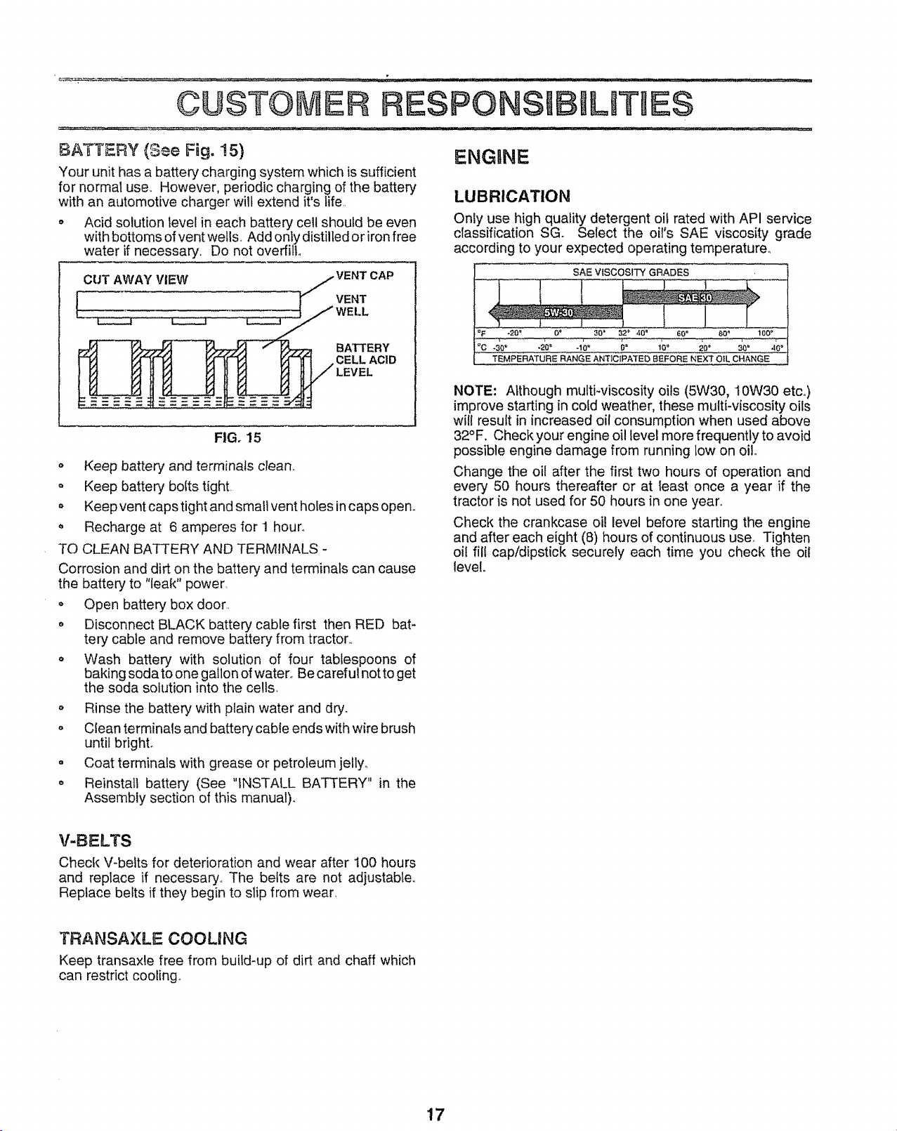
• Acid solution level in each battery cell should be even
with bottoms ofvent wells,, Add onty distilled or iron free
water if necessary. Do not overfill°
CUT AWAY VIEW ,j VENT CAP
rVENT
•.. .....'_ __"" WELL_:
BATTERY
CELL ACID
FIG. 15
o Keep battery and terminals clean,.
Keep battery bolts tight,
Keepvent capstight and small vent holes in caps openo
o Recharge at 6 amperes for 1 hour.
TO CLEAN BATTERY AND TERMINALS -
Corrosion and dirt on the battery and terminals can cause
the battery to "leak" power,
o Open battery box door..
o Disconnect BLACK battery cable first then RED bat-
tery cable and remove battery from tractor..
. Wash battery with solution of four tablespoons of
baking soda to one gallon of water_ Becareful not to get
the soda solution into the cells.
o Rinse the battery with plain water and dry°
o Clean terminals and battery cable ends with wire brush
until bright.
• Coat terminals with grease or petroleum jelly_
o Reinstall battery (See "INSTALL BATTERY" in the
Assembly section of this manual).
ENGmNE
LUBRICATION
Onty use high quality detergent oil rated with API service
classification SG. Select the oil's SAE viscosity grade
according to your expected operating temperature_
SAE VISCOSITY GRADES
:_F -20" 0_ 30 = 32 _ 40 _ 60" 80 '_ 100 °
TEMPERATURE RANGE ANTICIPATED BEFORE NEXT OIL CHANGE
NOTE: Although multi-viscosity oils (5W30, t 0W30 etco)
improve starting in cold weather, these multi-viscosity oils
will result in increased oil consumption when used above
32°F. Check your engine oil level more frequently to avoid
possible engine damage from running low on oil
Change the oil after the first two hours of operation and
every 50 hours thereafter or at least once a year if the
tractor is not used for 50 hours in one year,,
Check the crankcase oil level before starting the engine
and after each eight (8) hours of continuous use. Tighten
oil fill cap/dipstick securely each time you check the oii
level°
V-BELTS
Check V-belts for deterioration and wear after 100 hours
and replace if necessary., The belts are not adjustable.
Replace belts if they begin to slip from wear.
TRANSAXLE COOLING
Keep transaxle free from build-up of dirt and chaff which
can restrict cooling.,
17
 Loading...