

Page 1
BlEAm
OWNER’S
MANUAL
MODEL NO.
917.254611
Caution:
Read and follow
all Safety Rules
and Instructions
Before Operating
This Equipment
CRRFTSMRII®
12 HP
ELECTRIC START
38" MOWER DECK
5 SPEED TRANSAXLE
LAWN TRACTOR
Assembly
Operation
Maintenance
Service and Adjustment
Repair Parts
Sears, Roebuck and Co., Chicago, IL 60684 li.S.A.
Page 2

LOOK FOR THIS SYMBOL TO POINT
OUT IMPORTANT SAFETY PRECAU
TIONS. IT MEANS - ATTENTION! BE
A
COME ALERT! YOUR SAFETY IS IN
VOLVED.
NOTE: LOOK FOR THIS WORD TO POINT OUT IM
PORTANT INFORMATION ABOUT THE OPERATION
AND PERFORMANCE OF YOUR TRACTOR
CAUTION; LOOK FOR THIS WORD TO POINT OUT
IMPORTANT EQUIPMENT PRECAUTIONS.
A
WARNING: This unit is equipped with an internal combustion engine and should not be used on or near any unimproved forest covered,
brush covered or grass covered land unless the engine's exhaust system is equipped with a spark arrester meeting applicable local or area
laws (if anyj. If a spark arrester is used, it should be maintained in effective woiking order by the operator. (See REPAIR PARTS for part
number identification!.
In the State of California the above is required by law {Section 4442 of the California Public Resources Code) Other Slates m ay have similar
laws. Federal laws apply on federal lands.
Know Ihe controls and how to stop quickly, READ THIS
OWNER'S MANUAL and instructions furnished with attach
ments.
Do not allow children to operate the machine Do not allow
adults to operate it without proper ¡nstrudbn.
3.
Do not carry passengers Do not mow when children and
others are around
Always wear substantial footwear. Do no! wear toóse fitting
clothtng that could get caugnt in moving parts.
Keep your ayes and mind on your tractor, mower, and the
area being cut Do not let other interests distract you.
Do not attempt to operate your tractor or mower when not in
the driver's seat
Always get on or off your tractor from the operator's left hand
side,
Clear the work area of objects (wire, rocks, etc ) which might
be picked up and thrown
9,
Disengage all attachment clutches before attempting to start
the engine,
10
Disengaoe power to attachments and stop the engine before
leaving the operator's posittori.
11
Disengage power to mower, stop the engine, and disconnect
spark plug wire(s) from spark piug(s) before cleaning, making
an adjustment, or repair. Be careful to avoid touching hot
muffier or engine components
12
Disengage power to attachments when transporting or not in
use.
13
Take all possible precautions when leaving the vehicle
unattended. Disengage the power take-off, lowerthe attach
ments, shift into neutral, set the parking brake, stop the
engine, and remove the Hey
14
Do not stop or start suddenty when going uphill or downhill
Mow up and down the (ace of stopas (not greater than 15“),
never across the face Refer to page 51,
15
Reduce speed on slopes and make turns gradually to prevent
tipping or loss of control. Exercise extreme caution when
changing direction on slopes
16
While going up or down slopes, place gear shift control lever
in 1st gear position to negotiate Ihe slope without stopping.
17
Never mow in wet or slippery grass, when traction is unsure,
or at a speed which could cause a skid.
Ifl,
Slay alert for holes in the terrain and other hidden hazards
Keep away from drop-offs
19
Do not drive too close to creeks, ditches, and public high
ways.
20
Exercise special care when mowing around fixed objects in
order to prevent the blades from striking them. Never delib
erately run tractor or mower into or over any foreign objects
21
Never shift gears until tractor comes to a stop
22
Never place hands or feat under Ihe mower, in discharge
chute, or near any moving parts while tractor or mower is
funning, Always keep clear of discharge chute
23
Use care when pulling loads or using heavy equipment
a. Use only approved drawbar hitch points
b. Limit toads to those you can safely control
RULES FOR SAFE OPERATION
c. Do not turn sharply Use care when backing
d. Use counterweight or wheel weights when suggested in
owner’s тапиаГ
24, Watch out for traffic when crossing or near roadways
25, When using any attachments, never direct discharge of
material toward bystanders nor allow anyone near the ve
hicle while in operation,
26, Handle gasoline with care - it is highly llammable,
a Use approved gasoline containers
b- Never remove the fuel cap of the fuel tank or add
gasoline to a running or hot engine or an engine that has
not been allowed to cool for several minutes after run
ning Never fill tank indoors Always clean up spilled
gasoline
c, C^en doors if the engine is run in the garage - exhaust
fumes are dangerous Do not run the engine indoors.
27 Keep the vehicle anci attachments in good operating condi
tion, and keep safety devices in place and working.
28. Keep all nuts, bolts, and screws tight to be sure the equip
ment is in safe working condition.
29. Never store the equipment with gasoline in the tank inside a
building where fumes may reach an open flame or spark.
Allow the engine to cool before storing in any enclosure.
30. To reduce fire hazard, keep the engine free of grass, leaves,
or excessive grease, Do not clean product while engine is
running
31. Except for adjustments, DO NOT operate engine if air cleaner
or cover directly over carburetor aif intake is removed.
Removal of such part could create a fire hazard.
32. Do not operate without a muffler, or tamper with exhaust
system, Damaged mufliers or spark arresters could create a
fire hazard. Inspect periodically and replace it necessary.
33. The vehicle and attachments should be stopped and in
spected for damage after striking a foreign object, and the
damage should be repaired before restarting and operating
the equipment
34. Do not change the engine governor settings or overspead the
engine; severe damage or injury may result
35. When using the vehicle with mower, proceed as follows:
a Mow only in daylight or tn good artificial light
b. Shot the engine off when unclogging chute,
c Check the blade mounting bolts for proper tightness at
frequent intervals
36. Do not operate the mower without the entire grass catcher,
on mowers so equipped, or the deflector shield in place,
37. Disengage power to mower before backing up Do not mow
in reverse unless absolutely necessary and then only after
careful observation of the entire area behind the mower.
38 Under normal usage the grass catcher bag material is subjecl
to deterioration and wear, ft should be checked frequently for
bag replacement Replacement bags should be checked to
ensure compliance with the original manufacturer’s recom
mendations or speciftoations.
Page 3

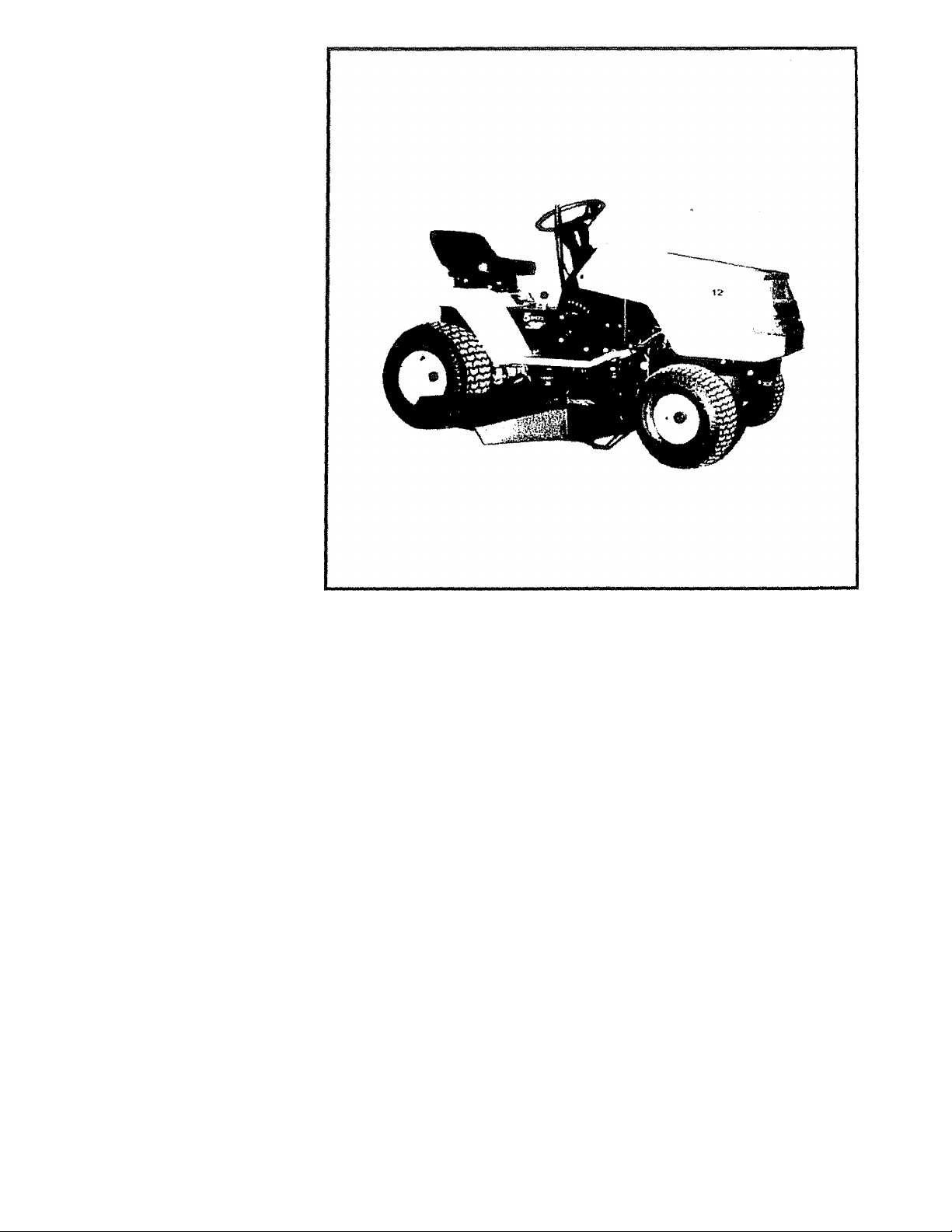
CONGRATULATIONS on your purchase of a Sears
Lawn Tractor, It has been designed, engineered and
SERIAL
NUMBER
you cannot easily remedy, please contact your nearest
Sears Service Department IVe have competent, well-
trained technicians and the proper tools to servte or
DATE OF PURCHASE
repair this unit
THE SERIAL NUMBER WILL BE FOUND ON THE MODEL
MAINTENANCE AGREEMENT
PLATE UNDER THE SEAT.
A Sears Maintenance Agreement is available on this
product. See the nearest Sears store or service centre
for details.
YOU SHOULD RECORD THESE NUMBERS AND KEEP
FOR FUTURE REFERENCE.
CUSTOMER RESPONSIBILITIES
Read atKl retain this manual. Study and observe the safety rules. Always use care when using your tractor. Always
keep your tractor and mower clean, Folbw a regular schedule In maintaining, caring for, and using your tractor. A well
carecf for tractor will run better and last bnger.
ATTACHMENTS
This unit can use many attachments now available at your Sears store. It cannot use attachments that engage the ground
like a plow, harrow, cultivator, or tiller. See page SO for a list of available attachments.
LIMITED ONE YEAR WARRANTY
ON ELECTRIC START RIDING EQUIPMENT
For one year from date of purchase, when this riding equipment is maintained, lubricated, and tuned up according to
the operating and maintenance Instruction in the owner's manual, Sears will repair free o( charge any defect in
material or workmanship in this electric start riding equipment.
This wan-anty excludes blade(s), blade adapter(s), spark plugfs), air cleaner and belt(s), which are expendable and
become worn during normal use,
This warranty does not cover:
• Tire replacement or repair caused by punctures from outside objects {such as nails, thorns, stumps, or
glass): and
• repairs necessary because of operator abuse or negligence, including the failure to maintain the equip
ment according to instructions contained in the owner's manual; and
" riding equipment used for commercial or rental purposes,
FULL 90 DAY WARRANTY ON BATTERY
For 90 days from the date of purchase, if any battery included with this riding equipment proves defective in material
or workmanship and our testing determines the battery will not hold a charge, Sears will replace the battery at no
charge.
WARRANTY SERVICE IS AVAILABLE BY CONTACTING THE NEAREST SEARS SERVICE CENTER/DEPARTMENT.
This warranty gives you specilic legal rights, and you may also have other rights which may vary from state to state
SEARS. ROEBUCK AND GO, D/731CR-W SEARS TOWER, CHICAGO. IL 60684
NOTE: THE ILLUSTRATIONS SHOWN IN THIS MANUAL ARE TO AID IN THE ASSEMBLY AND OPERATION OF
YOUR TRACTOR. THEY MAY OR MAY NOT SHOW THE ACTUAL MODEL YOU HAVE PURCHASED,
Page 4

A Filter:
Adjustments; Air Cleaner..............................16
Brake
________________.
Cariiuretor
Mower Drive Belt
........................
.......
.........
Mower Storage
Front'To-Rear
Side-TdSide
........
....................
Throttle Control Cable ....
Engine Valves
Air Cleaner
Air Screen, Engine
.......................
...................................
.............
...
Asserrtily......................................
Attachments
......................................„50
B Tractor Pivot Points................
.....
14
.
......18 Fuel:
.....
22
...............23 Fuse
.
.....
22
.....
18
......
18
Hood Removal/lnstallation
Fuel
................................
Type
............................
...
.....................
......................................
H
.............
.....18
.
.....10
.
....
.
.......19 Parts Bag
....
......16 Repair and Adjustments......... 14-24
........
.....
....
16
5^9
Leveling Mower Deck
L
................. .
.....22 Carburetor
Lubrication:
Chart
............................
..
.
....
Battery:
Charging
Cleaning
Installation
Levels
Preparation............................
Starting with Weak Batter) ....17 Battery......................
Storage
Terminals..................................15 Brake Adjustment...................
Belt: Engine Oil
Motion Drive Fuel Filler.............................
Mower Drive Sparkplug
Blade:
Sharpening
Replacement.............................
Brake Adjustment
CartHjretor Adjustment
Controls, Tractor
Cutting Level, Mower
...
...................
...........................
.....
...................
......................................
.....
.
.7, 17 M
.
.....
15 Maintenance
.
........8
15
Air Cleaner
Foam Pre-cleaner
........7 Air Screen, Engine ...
............................
Removal/Replacement
....
...
.23 Blade Sharpening
....
19
Lubrication Chart
Removal/Replacement Tire Care.
Adjustment
........................22
Mower;
Adjustment, Front-to-Rear
.................
..................................
... .....
...
..14 Adjustment, Side-to-Side. ......22
.....14 Blade Sharpening
.
......
14 Blade Replacement
Cutting Level,
C
..........................
..........
...........................
.............................
E
....
.18
.........9 Removal
12,22
Installation
Operation
Mowing Tips
Muffler
.....................................................
Spark Arrester................................ .2,32
.......................
.........
............................
.........
...............
.
.....
........
......................
.................. ......24
.......
...........................18
....
.............. ..........
..................
............
.....
.......
...........12,22
...........
..........................
......................................
........................................
.................................
.......
.....
.
.........
.........
...
....
....
.....16
..,..15
....
.....14
.....16
.....18
..8,14
.
....
.....
.....
....
......
....
......
20 R
..24
17
„13
16 Mower Adjustment
16 Front- to-Rear
14
23
14
14
21
,11
21
,12
17
Cations:
Attachments...
Spark Arrester
...........................
......
..............2,32
P
Parking Brake
Parts,- Replacement/Repair
Blade...
Fuse
.........................
....
................................
.............
......
..................
........
.......
....
..................
............
.
......
Hood Removal/lnstallation .....20
Motion Drive Bell
Removal/Replacement
Mower Drive Belt
Removal/Replacement
..................
Side-to-Side
Mower Removal
Tire Care
Repair Parts
.....................
.....
..........
......................
..............................
.
S
Safety Rules
Seat............................
Service Record.........
........
....................
........................
.........
Slope Guide Sheet.....................
Sparkplug
Speed Control Chart
Starting the Engine
Steering Wheel,.
....................................
.............................
................
..... ...
.......................
Stopping the Tractor...................
Storage.....................................................
T
Throttle Control Cable
Adjustment
Tires.......................
..........................
.
......................
.........
Engine: Trouble Shooting Chart................
Air Screen
Oil Change
Oil Level.......................
Oil Type
Preparation.............................
Repair Parts
Starting
Storage
..................
......
.
.....................
.
.................................
.........
..................42-46
..................................
...........................
.
.....16
....
15 Oil;
.....16
.....
16 Engine .................................
....
10
....
10
Cold Weather Conditions . .16
Storage
.............
Operation
.....................................
(Iterating Your Mower
0
...................
..............
.....23 Operating Your Tractor
Starting the Engine
.................
Stopping Your Tractor
Tractor Operation on Hills. .....12
............
_______
.....16
.....11
.....11
.....10
.
....
,9-12
23
10
Transaxle:
Repair Parts
Warranty
Transporting
....
_______________ _
Valve Adjustments.
Warranty
....................
Wiring Schematic
.................
.........
.........................48
V
................
.........
W
.........
.
.........................
.
.
....
.
........
.
.
50
....5-6
28-46
.....14
....
18
.....19
.....19
.....22
....
23
21
....
14
28-46
......
.......8
13
....
51
....
18
.....
12
......11
......
10
.....
23
.....18
.8,14
25-26
40-41
.....12
18
......
....
22
2
7
3
27
4
Page 5
ASSEMBLY
To assemble tractor you will need;
(2) 7/1 &" wrenches Tire Pressure Gauge
{1) 1 /2" wrench Screwdriver
(2) 9/16" wrenches Utility Knife
{1) 3/4" wrench 5/16" Wrench
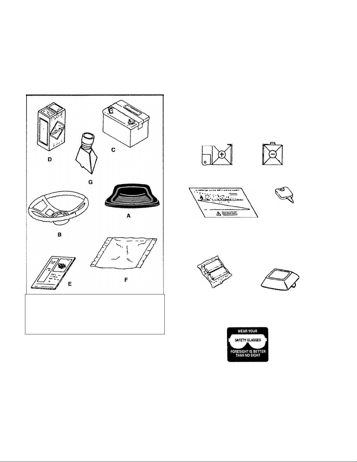
Take all of the Items out of the box. The box contains the Items shown below. Open the parts bag and check the
contents (see page 6).
Parts bag contents not shown full size
(2) Battery Carriage Bolts -1/4 x 20 x 7 1/2
Terminal Guard
a. Seal d
b.
c
NOTE: RIGHT HAND(R.H ) AND LEFT HAND (L.H.) ARE
Steering wheel e. Owner's Manual
Battery
DETERMINED FROM OPERATOR’S POSITION
WHILE SEATED ON THE TRACTOR
Battery Acid
f
9
Parts Bag
Steering Boot
(2) Keys
15° Slope Instruction
m
steering Wheel Adapter
Battery Caps and
Instructions
The operation of any tractor can result in foreign objects
thrown into the eyes, which can result in severe eye dam
age Always wear safety glasses or eye shields before start
ing your tractor and while moving We recommend Wide Vi
sion Safety Mask for over the spectacles or standard safety
glasses, available at Sears Retail or Catalog Stores
Steering Wheel Insert
Page 6
ASSEMBLY
ASSEMBLY
LOCATION
BATTERY
BATTERY
TERMINALS
SEAT
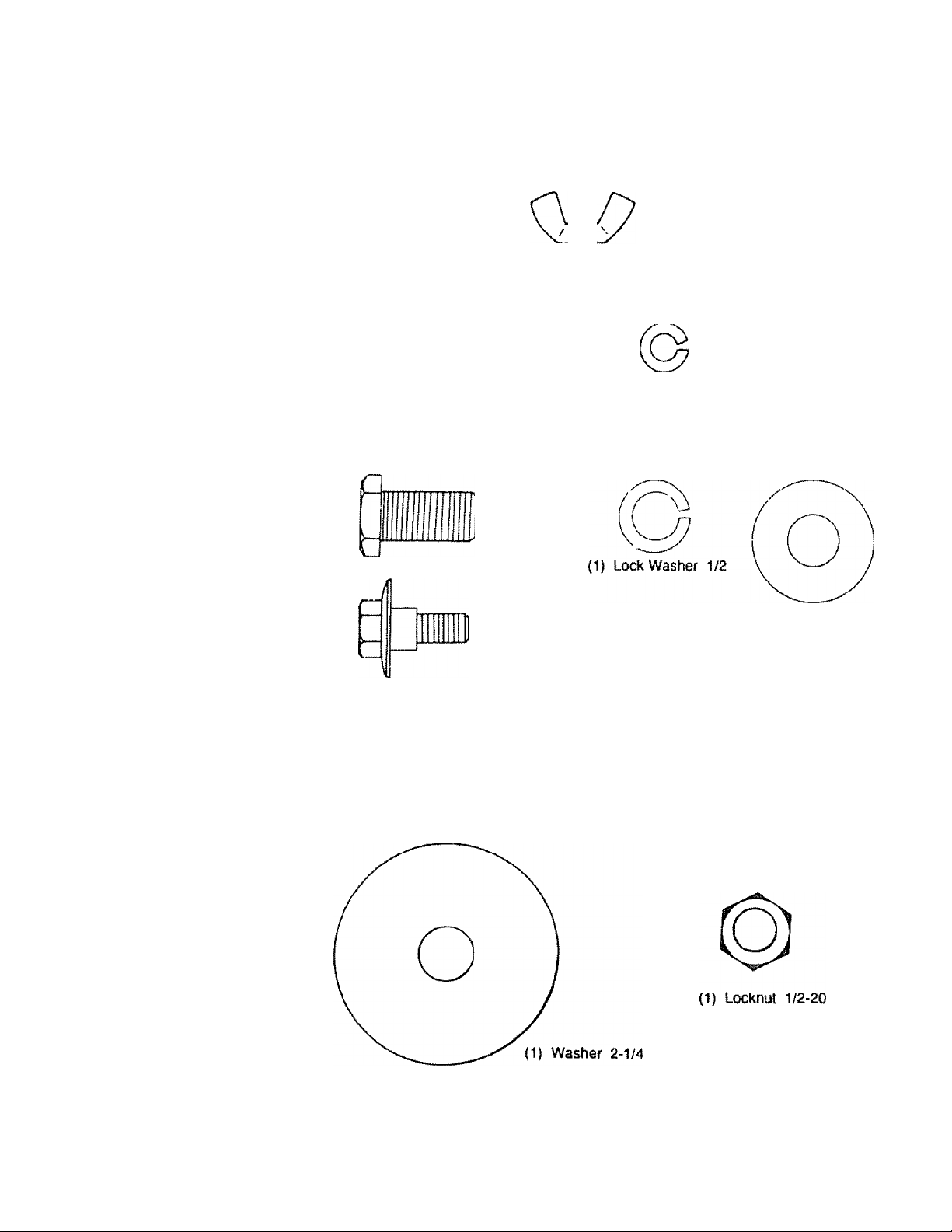
PARTS BAG CONTENTS SHOWN FULL SIZE
(2) Wing Nut 1/4-20
(2) Hex Bolt 1/4-20x3/4 (2) Lock Washer 1/4
O
{2) Washer 9/32 x 5/8 x 16 Ga
(1) Adjustment Boll
(2) Hex Nut 1/4-20
STEERING
BUSHING
STEERING
WHEEL
(1) Washer 17/32 x
1-3/16 x 12 Ga
(1) Shoulder Bolt 5/16-18
(2) Sheet Metal Screw 10-16 x 1/2 ABTBS
Page 7
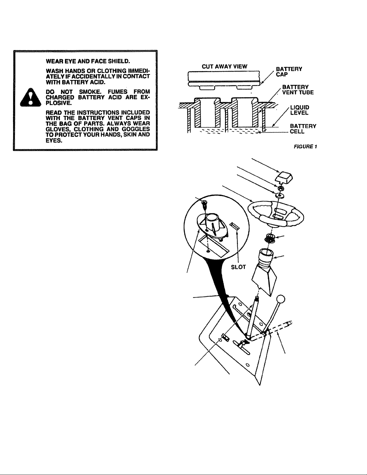
1. Pr^iare Banery
ASSEMBLY
Fill and charge battery {before installing)- NOTE: SEE DE
TAILED INSTRUCTIONS PACKAGED WITH BATTERY
VENT CAPS FOUND IN BAG OF PARTS.
a. Fill each cell with battery acid. Add the acid until it
reachesihe bottom of the vent tubes (Fig. 1}, Do not
add the acid beyond this level or the additional acid
can come out when the battery is charged
b. After cells are filled, tilt battery from side to side to
release air bubbles.
c. Allow battery to stand and settle for at least thirty
minutes. If the level of acid falls below the point de
scribed in step (a), add more acid until the correct
level is reached. Install the battery caps, found in the
bag of parts, to coverthe vent tubes. Wash!he top of
the battery with water to remove any acid, then wipe
dry.
d. Check battery case for leakage to make sure that no
damage has occurred in handling
e. Neutralize excess battery ackJ for disposal by add
ing it to 2 gallons (7 litres) of water in a five gailon (20
litres) plastic container. Stirwith a wooden or plastic
paddle while adding baking soda until the addition of
more soda causes no more foaming
f. it is recommended that the battery be charged be
fore use. Use a 12 volt battery charger Charge bat
tery at a rate of 6 amperes for 1 hour. NOTE: OB
SERVE SAFETY PRECAUTIONS, LISTED IN BOX
ABOVE, REQUIRED FOR BATTERY CHARGING.
Check the acid level after the battery is charged. If
the acid has fallen below the correct level, add dis
tilled or iron free water
2. Unpack Tractor
a. Cut down four comers of the carton with utility knife
and fold down sides.
b. Disengage parking brake and position front wheels
straight ahead (see page 9)
c Install steering wheel
Slide the steering bushing over the steering
1.
shaft (Fig, 2).
Position steering shaft forward until screw hoies
in dash line up with steering bushing install two
(2) screws (Fig 2)
Position steering boot over steering shaft
3.
Place bottom of steering boot over two slots in
4,
dash (Fig 2)
1/2" NUT
2 -1/4” DIA. WASHER s
STEERING WHEEL ^
SCREW-
STEERING
WHEEL
ADAPTER
STEERING
BOOT
STEERING
BUSHING
STEERING SHAFT
(REC’D. POSITION)
STEERING SHAFT
(INST. POSITION)
FIGUREZ
5 Push steering boot down into aligning slofe on
dash6 Place steering wheel adapter on steering shaft
7 With front wheels pointed straight ahead, place
steering wheel on steering wheel adapter Bars
of steering wheel should point straight across
tractor.
Page 8
ASSEMBLY
SHOULDER
BOLT
ADJUSTMENT
BOLT LOCK
WASHER
Fiauma
POSITIVE WASHER
TERMINAL
FLAT
WASHER
WASHER NEGATIVE
TERMINAL
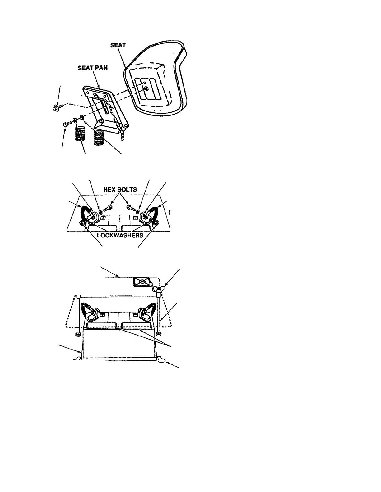
3. Install Seat
a. Remove cardboard from seat pan.
b Place seal on seat pan. Screw adpstment bolt, lock
washer and flat washer into seat (Fig. 3). ^rew
shoulder bolt into seat (Fig. 3). Adjustment bolt,
shoulder bolt and washers found in bag of parts
(shown full size on page 6).
c. Tighten shoulder bolt using a 1/2" wrench. NOTE:
THE SHOULDER BOLT WILL BE LOOSE IN THE
SEAT PAN SLOT.
d Tighten adjustment bolt, lock washer and flat wash
er securely.
NOTE: SEAT POSITION SHOULD BE ADJUSTED FOR
WARD OR BACKWARD SO THAT THE OPERA
TOR CAN COMFORTABLY REACH CLUTCH/
BRAKE PEDAL AND SAFELY OPERATE TRAC
TOR.
e Place seat in operating position. Sit on the seat and
press clutch/brake pedal all the way down, if operat
ing position is not comfortable, adjust seat.
f. To adjust: raise seal. Loosen adjustment bolt. Slide
seat to desired position. Tighten adjustment bolt se
curely.
POSITIVE
CABLE
(RED)
FIGURES
WING NUT
BATTERY
TRAY
FIGURES
d.
e
f
NEGATIVE
CABLE
HEX NUTS''
TERMINAL
GUARD
BATTERY
DRAIN TUBE
8 Place 2 1/4” diameterwasheron steering shaft
and install a 1/2" locknut (washer and locknut
found in bag of parts) Tighten securely.
9. Snap insert into steering wheel
Remove plastic on tractor hood.
Raise attachment lift handle (see page 9)
Roll Tractor off skid. Be careful of staples in skid
WING NUT
BATTERY
BOLT
ACCESS
DOORS
KEY
HOLE
ADJUSTMENT BOLT, LOCK WASHER
AND FLAT WASHER MUST BE TIGHT
A
4. Check Tires
Check the air pressure in the tires. Tires with too much air
pressure will cause the unit to ride tough. The wrong air
pressure will also keep the mower from cutting level. The
correct air pressure is shown on the side of the tires, if the air
ressure is not shown, set to pressures shown in the RE
P
AIR AND ADJUSTMENT section (page 14).
S. Install Battery
A
A
ENED SECURELY TO PREVENT MOVE
MENT OF SEAT.
BEFORE INSTALLING BATTERY. RE
MOVE METAL BRACELETS, WRIST
WATCH BANDS, RINGS, ETC. FROM
YOUR PERSON. TOUCHING THESE
ITEMS TO BATTERY TERMINALS
COULD RESULT IN BURNS.
WEAR EYE AND PACE SHIELD.
WASH HANDS OR CLOTHING IMMEDI
ATELY IF ACCIDENTALLY IN CONTACT
WITH BATTERY ACID.
DO NOT SMOKE. FUMES FROM
CHARGED BATTERY ACID ARE EX
PLOSIVE.
READ THE INSTRUCTIONS INCLUDED
WITH THE BATTERY VENT CAPS IN
THE BAG OF PARTS. ALWAYS WEAR
GLOVES, CLOTHING AND GOGGLES
TO protect your HANDS, SKIN AND
EYES.
8
Page 9
ASSEMBLY
a Lift seal (Fig 3)
b Lower battery into fender well with battery terminals
toward front of tractor {Fig 4) Make sure battery
rests in battery tray (Fig 5)
NOTE: BE SURE BATTERY DRAIN TUBE IS SECURELY
ATTACHED TO BATTERY TRAY DRAIN (Fig 5)
POSITIVE TERMINAL MUST BE CON
NECTED FIRST TO PREVENT SPARKS
A
FROM ACCIDENTAL GROUNDING.
Connect RED battery cable to positive {+) battery
terminal with hex bolt, flat washer, lock washer and
hex nut (shown full size on pg 6) found in bag of
parts Tighten securely with two 7/16" wrenches
(Fig 4)
d Connect BLACK ground cable to negative (-) bat
tery terminal with remaining hex bolt, flat washer,
lock washer and hex nut (shown full size on pg 6)
found in bag of parts Tighten securely (Fig 4),
e To prevent corrosion, apply grease to the battery
terminals after installing cables.
f Slide two battery bolts through terminal guard and
start the wing nuts onto the threads (Fig 5)
g Position terminal guard over battery as shown (Fig
5) and align bolt heads with key holes next to battery
tray (Fig,5)
h Lower boll heads into key holes and slide square
shafts of bolts into slots of key holes (Fig, 5)
i Tighten wing nuts
j Close terminal access doors
CAUTION:
DO NOT START ENGINE UNTIL YOU HAVE
REVIEWED THE OPERATION SECTION OF
THIS MANUAL
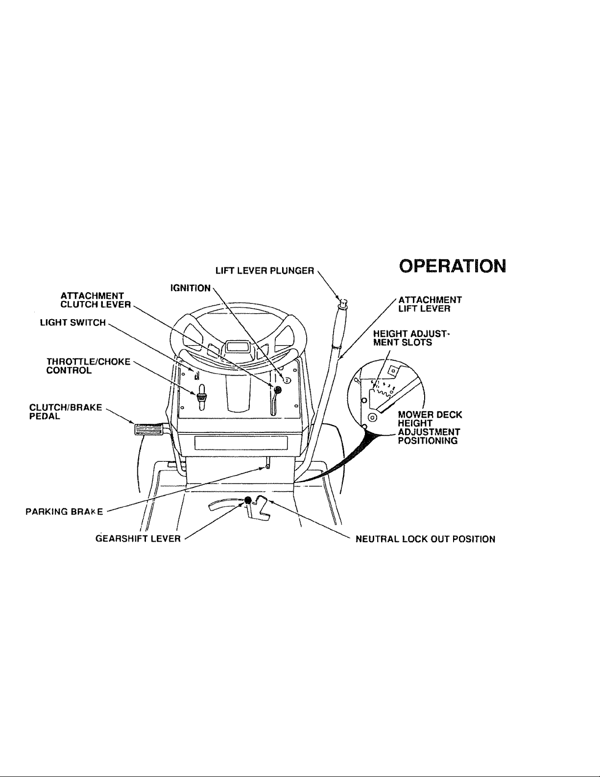
KNOW YOUR TRACTOR
ATTACHMENT CLUTCH LEVER: Push lever up to engage
attachment There will be an engine hesitation as the clutch
engages
ATTACHMENT LIFT LEVER: Use the attachment lift lever
to raise and lower the attachment rrounted to your tractor.
Pul! lever back slightly and push button, then move the lift
lever forward to lower attachment
CLUTCH/BRAKE PEDAL: The pedal has 2 lunctions; a
clutch and a brake To engage the brake push the pedal
completely down
HEIGHT ADJUSTMENT: Use the height adjustment slots
to adjust the mower height. Push the attachment lift lever
plunger down and position the attachment lilt lever into the
desired slot Release lilt lever plunger
GEARSHIFT: Press the clutch/brake pedal down firmly and
move gearshift lever to desired speed
IGNITION: Place key in ignition and turn to the right to start
The switch spring returns from the start position
LIGHT SWITCH: Turns the headlights on and off
PARKING BRAKE: To set the parking brake, push the
clutch/brake pedal completely down. Hold the parking brake
lever in "Engage" position and release pressure from pedal
Clutch/brake pedal will remain in brake position.
THROTTLE/CHOKE CONTROL: Use the throttle control to
increase or decrease the speed of the engine, and to choke
the engine for starting Push lever to the right andfonwardto
choke
NEUTRAL LOCKOUT POSITION: Transmission is disen
gaged when gearshift lever is in tWs position.
Page 10
OPERATION
AIR SCREEN
IGNITION KEY
1. Stopping Your Tractor
NOTE; REMOVE KEY WHEN LEAVING TRACTOR TO
PREVENT UNAUTHORIZED USE:
a Push clutch-brake pedal into lull “BRAKE" position.
Keep your foot on pedal (Fig 7).
b Place attachment clutch lever in "DISENGAGED"
position.
c. Move gear shift lever tp “NEUTRAL" position.
d. Lift up to place parking brake in "ENGAGED" posi
tion (Fig. 10) and release pressure from clutch/
brake. Pedal should remain in "BRAKE" position.
e Move throttle control to "S" (slow) position.
f. Turn ignition key to "OFF" position Never use choke
to stop engine,
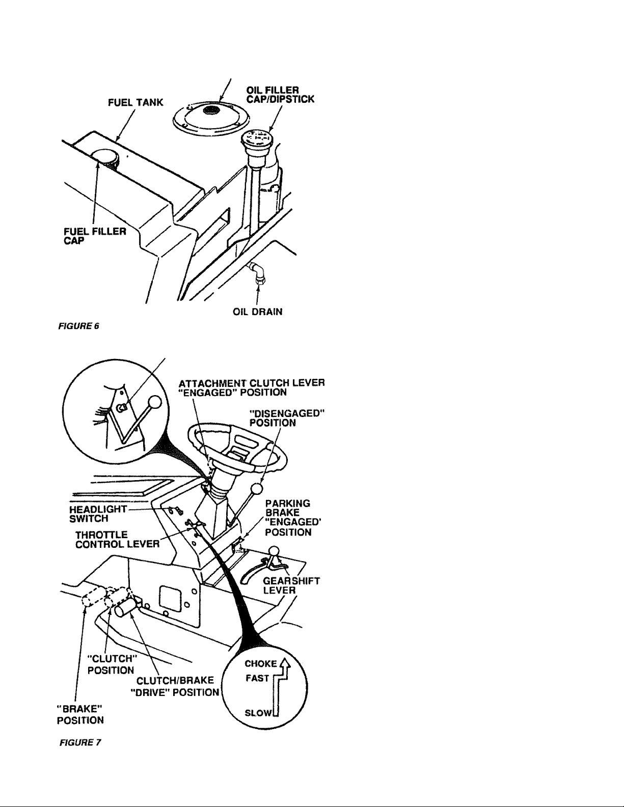
2. Preparing the Engine
LEARN TO STOP YOUR TRACTOR BE
FORE ATTEMPTING TO START THE EN
A
a This engine has been shipped filled with summer
Changing oil after the first two hours (or two mowings) will
help eliminate break-in residue which might be damaging to
your engine
b Fill fuel tank (Fig. 6). Use fresh, clean, regular un
GINE.
weight oil (For cold weather operation see chart
page 16). Check engine oil level. Refer to REPAIR
AND ADJUSTMENT section (page 16)
leaded gasoline. Capacity is 5 quarts (4.73 litres).
NOTE: FRESH. CLEAN WINTER GRADE FUEL MUST
BE USED TO INSURE GOOD COLD WEATHER
STARTING
FILL TO BOTTOM OF GAS TANK
FILLER NECK. DO NOT OVERFILL.
WIPE OFF ANY SPILLED OIL OR FUEL.
A
CAUTION:
DO NOT STORE, SPILL OR USE GASO
LINE NEAR AN OPEN FLAME.
EXPERIENCE INDICATES THAT ALCOHOL
BLENDED FUELS (CALLED GASOHOL OR
USING ETHANOL OR METHANOL) CAN AT
TRACT MOISTURE WHICH LEADS TO
SEPARATION AND FORMATION OF ACIDS
DURING STORAGE, ACIDIC GAS CAN
DAMAGE THE FUEL SYSTEM OF ANY EN
GINE WHILE IN STORAGE.
TO AVOID ENGINE PROBLEMS, THE FUEL
SYSTEM SHOULD BE EMPTIED BEFORE
STORAGE FOR 30 DAYS OR LONGER
DRAIN THE GAS TANK. START THE EN
GINE AND LET IT RUN UNTIL THE FUEL
LINES AND CARBURETOR ARE EMPTY,
USE FRESH FUEL NEXT SEASON. SEE
STORAGE INSTRUCTIONS FOR ADDI
TIONAL INFORMATION
NEVER USE ENGINE OR CARBURETOR
CLEANER PRODUCTS IN THE FUEL TANK
OR PERMANENT DAMAGE MAY OCCUR.
10
Page 11
3. starting the Engine
a. Move throttle control lever (Fig, 7) past "FAST” to
the “CHOKE" position.
b. Fully depress clutch/brake pedal
c. Turn ignition key to “START" and release key as
soon as engine starts
CAUTION: DO NOT RUN STARTER CONTINUOUSLY
FOR MORE THAN FIFTEEN SECONDS PER
MINUTE.
d. If engine does not start alter (our or fiYe tries, move
throttle control lever to “FAST* position, wait a few
minutes and try again It the engine does not start
after four or five more tries, see the
TROUBLESHOOTING Chart (page 25}
e. After the engine starts move throttle control lever
slowly to the “SLOW" position
I To start a hot engine move the throttle control lever
to a position between “FAST and “SLOW"
OPERATION
ATTACHMENT CLUTCH
LEVER “ENGAGED"
POSITION
ATTACHMENT CLUTCH / LIFT LEVER
LEVER “DISENGAGED" PLUNGER
POSITION
LIFT LEVER
"HIGHEST"
POSITION
LIFT LEVEF
“LOWEST"
POSITION
READ THE "RULES FOR SAFE OPERA
TION" CAREFULLY BEFORE OPERAT
ING YOUR MOWER.
DO NOT OVER LOAD TRACTOR BY
TOWING WEIGHTS GREATER THAN
150 POUNDS (68 KG).
ALWAYS WEAR SUBSTANTIAL FOOT
A
WEAR AND AVOID LOOSE FITTING
CLOTHING THAT COULD GET
CAUGHT IN MOVING PARTS.
DO NOT OPERATE THE MOWER WITH
OUT EITHER THE ENTIRE GRASS
CATCHER, ON MOWERS SO
EQUIPPED, OR THE DEFLECTOR
SHIELD IN PLACE.
CAUTION
TO AVOID INJURY
1. Read owner’s manual.
2. Know location and function of alt controls.
3. Keef) guards, safety shield and switches in place and
working.
4. Remove objects that can be thrown by blades.
5. Do not mow when children and others are around.
6 Never carry children or passengers.
7. Always look behind machine before backing.
8. Do not mow where machine can tip or slip.
9. If machiné stops going uphill, stop blades and back
slowly down.
10. Be sure blades and engine have stopped before placing
hands or feet near the blades.
11. Remove key when leaving machine .
R.H. RUNNER
DISCHARGE
GUARD
WHEN PARKING BRAKE IS ENGAGED,
MAKE SURE IT WILL KEEP TRACTOR
FROM MOVING.
A
NEVER PLACE YOUR HANDS OR FEET
IN OR UNDER ANY POWERED ATTACH
MENT OR NEAR ANY MOVING PART
WHILE TRACTOR OR ANY POWERED
ATTACHMENT IS RUNNING.
4. Operating Your Lawn Tractor and Mower
NOTE: THIS TRACTOR IS EQUIPPED WITH AN OPERA
TOR PRESENCE SENSING SWITCH. ANY AT
TEMPT BY THE OPERATOR TO LEAVE THE
SEAT WITH THE ENGINE RUNNING AND THE
ATTACHMENT CLUTCH LEVER ENGAGED WILL
SHUT OFF THE ENGINE.
CAUTION: DO NOT ADD ADDITIONAL WEIGHT
TO THE TRACTOR OTHER THAN THE OP
TIONAL WHEEL WEIGHTS. EXCESSIVE
WEIGHT MAY OVERLOAD AND DAMAGE THE
TRANSAXLE,
a Depress lift lever plunger and move the attachment
lift lever to the highest position See Fig 8.
b Start the engine. (See Starting the Engine)
c Move the throttle lever to mid range position. Fully
depress clutch/brake pedal. Select a low (Is! or 2nd)
gear until you become more familiar with the opera
tion of the unit
11
FIGURES
Page 12

OPERATION
r
figure 9
FUNCTION
Normal
Mowing
Heavy Mowing
Snow Blowing
r
c
«
................
SPEED SELECTION GUIDE
...
: "
GEARSHIFT
2 or 3
1 or 2
1
. j
)
j
THROTTLE
‘
Ì9>
FAST
- '
Ì
/
a. Mower should be adjusted properly front to back
and side to side for good mowing performartce. Re
fer to REPAIR AND ADJUSTMENT section {page
22)
b. Use the runner on the R.H. side as a guide; the
blade cuts approximately an irrch outside the runner
(Fig. 8).
c Drive so that clippings are discharged onto thè area
that has been cut. Have the cut area to the right of
the machine. This will result in a more even distribu
tion of clippings and more uniform cutting.
d.
from shaibs, feixes, driveways, etc. After two or
three rounds, mow in the opposite direction making
left hand turns until finished.
If grass is extremely tall, it should be mowed twice
The first time cut relatively high; the second time to
the desired height
The left hand side of mower should be used for trim
f,
ming.
See Speed Selection Guide (above)
g
Do not mow tall, dry (brown) grass over 6 inches
h.
(15 24 cm) tail It is a fire hazard
6. Operating the Tractor on Hills
4-5
2
SLOW-
FAST
Snow Blade
Transport
d. Slowly release clutch/brake pedal and proceed to
the mowing area.
e Stop the unit, then select a mowing speed {See
Speed Selection Guide, page 12).
f. Move throttle lever to half throttle and slowly move
attachment clutch lever to engaged position, Fig 8
g Slowly release clutchA)rake pedal
h Move throttle lever to fast position
i Observe height of cut and readjust as desired (see
page 9)
CAUTION: BEFORE YOU MOVE THE GEARSHIR
LEVER, COME TO A COMPLETE STOP.
FAILURE TO DO SO CAN RESULT IN GEAR
BOX DAMAGE
5. Mowing Tips
NOTE: TIRE CHAINS CANNOT BE USED WITH THE
MOWER ATTACHED.
DO NOT DRIVE UP OR DOWN HILLS
WITH SLOPES GREATER THAN 15“
AND DO NOT DRIVE ACROSS ANY
A
a. Move gearshift lever to 1st" gear before starting up
b. AVOID STOPPING OR SHIFTING ON HILLS.
c. if stowing is necessary, move throttle control lever
SLOPE. REFER TO PAGE 51.
or down hills
to slower position
LEAVE ENOUGH ROOM WHEN STOP
PING AND STARTING TO ALLOW
SLIGHT TRACTOR ROLL DOWNHILL
A
e To restart tractor movement, make sure tractor is in
f Make all turns gradually
AS CLUTCH/BRAKE PEDAL MOVES
THROUGH CLUTCH POSITION.
If stopping is absolutely necessary, push clutch/
brake pedal quickly to brake position.
the lowest speed range (“1st" Gear) and release
ciutch/brake pedal SLOWLY.
7. Transporting Your Tractor
For pushing or towing your tractor, place gearshift lever
in “N" positon Do not tow or push at more than 6 MPH
(9 7KPH),
12
Page 13

To kmpyourtmctorrunning better and longer,
perform necessary service using the follow
ing maintenance schedule:
WITH EVERY MOWING
1 Make sure all nuts on bolts are tight and cotter pins and
retainer springs are secure
2 Observe all safety precautions,
3 Keep tractor well lubricated (refer to page 24)
4 Make sure areas around muffler, engine and mower
deck are clean and free of debris buildup.
MAINTENANCE
FOR ANY ADJUSTMENTS, INSPEC
TION OH MAINTENANCE:
1. PUSH TRACTOR CLUTCH/BRAKE
PEDAL COMPLETELY INTO
"BRAKE" POSITION.
2. MOVE gearshift TO "N” NEUTRAL
POSITION.
3. PLACE PARKING BRAKE IN “EN
GAGED” POSITION. REMOVE FOOT
FROM PEDAL.
4. PLACE ATTACHMENT CLUTCH
LEVER IN "DISENGAGED" POSI
TION.
A
5. TURN IGNITION KEY TO "OFF" PO
SITION.
6. MAKE ABSOLUTELY SURE THE
BLADES AND ALL MOVING PARTS
HAVE COMPLETELY STOPPED.
7. REMOVE THE IGNITION KEY.
8. DISCONNECT THE SPARK PLUG
WIRE FROM THE SPARK PLUG AND
KEEP WIRE AWAY FROM THE PLUG
TO PREVENT INJURY FROM ACCI
DENTAL STARTING. BE CAREFUL
TO AVOID TOUCHING HOT ENGINE
OR MUFFLER COMPONENTS.
SERVICE RECORD
FILL IN DATES
Change Engine Oil
Check Brake Operatton
Check Tire Pressure
Clean Air Screen
Clean Air Cleaner
Lubricate Pivot Points (see page 24)
Check Battery Level and Recharge
Clean Battery and Terminals
Carburetor Adjustment
V-Belt Adjustment
Clean Engine Cooling Fins
Chedt Muffler
Replace Air Cleaner Paper Cartridge
Replace Spark Plug
Replace Fuel Filter
REGULAR SERVICE ocnviuc i co
|/
✓
DATES
✓
✓
✓
✓
Adjust Valves
13
Page 14
REPAIR AND ADJUSTMENT
HUB CAP WASHERS
SQUARE KEY
(REAR TIRE ONLY)
FIGURE 11
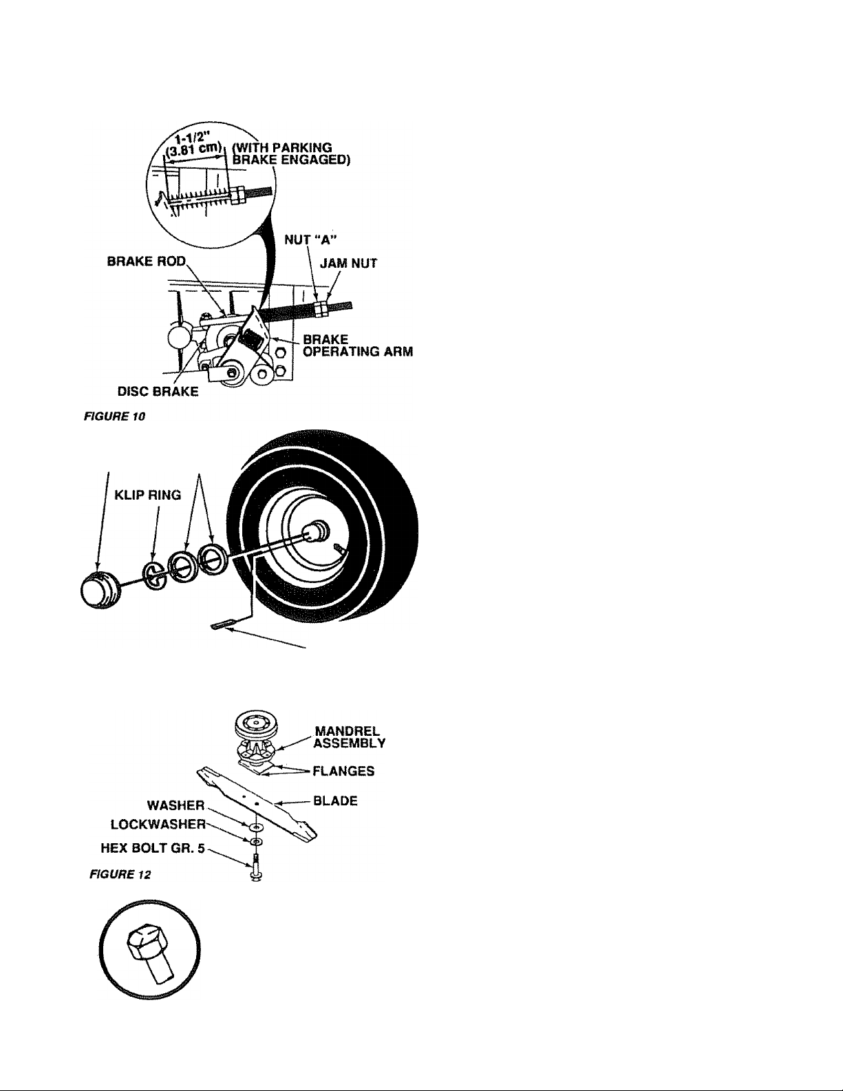
1. Brake Adjustment
This tractor is equif^jed with an adjustable brake system
mounted on the ngnt side of the fransaxle (F^. 10).
IF TRACTOR REQUIRES MORE THAN
SIX FEET (1.8 METERS) STOPPING
A
a Depress ciutch/brake pedal and engage parking
b Measure distance between brake operating arm
c. If distance is other than 1-1/2" (3.81 cm), loosen
Road lest tractor for proper stopping distance as stated
above Readjust if necessary. If stopping distance is still
greater than 6 feet (18 meters) in highest gear, further
maintenance is necessary Contact your local Sears Serv
ice Center
DISTANCE IN HIGHEST GEAR, THEN
BRAKE MUST BE ADJUSTED.
brake. . .
and nut “A” on brake rod,
jam nut (Fig. 10) and turn nut until distance be
comes 1-1/2” (3 81 cm). Retighten jam nut against
nut “A".
2, Tire Care
a Maintain tire pressure in front at 14 PSt (1Kg/cm^)
and rear tires at 10 PSI (0.7 Kg/cm'')
b Keep tires free of gasoline, oil. or insect control
chemicals which can harm rubber
c Avoid stumps, stones, deep mfs, sharp objects and
other hazards that may cause tire damage
d, Removing wheel for lire repair (Fig 11).
1 Block up axle securely
2. Remove hub cap, klip ring and washer to allow
wheel removal (rear wheel contains a square
key - Do Not Lose).
3. Repair lire and reassemble. Align slots in rear
wheel hub and axle. Insert square key. Re
place washers and snap klip ring securely in
axle groove. Replace hub cap.
NOTE: USE GREASE FITTINGS TO LUBRICATE FRONT
WHEELS WITH GENERAL PURPOSE GREASE.
APPLY AN ANTI-SEIZE OR GOOD GENERAL
PURPOSE GREASE TO LUBRICATE REAR AX
LES,
3. Blade Care
For best resutts,nvDwer blades must be kept sharp, The
blades can be sharpened with a few strokes of a file, or on a
grinding wheel. We suggest they be sharpened after every
25 hours of mowing Do not attempt to sharpen while on
mower. If you mow in sandy soil check the blades after each
two mowings The sand wears the blades away rapidly
a Blade Replacement
Raise mower to highest position to permit access lo
blades
1. Remove the hex head bolt, lockwasher and flat
washer (Fig 12) (turn counterclockwise)
2. Retrave and discard old blade
3. Clean top and bottom of mower housing
4 Install new blade with SHARP EDGE DOWN
and secure with flat washer, lockwasher and
hex head bolt. TIGHTEN SECURELY.
A GRADE 5 HEAT TREATED
BOLT CAN BE IDENTIFIED BY
THREE LINES ON THE BOLT
HEAD AS SHOWN AT LEFT.
14
A
ALWAYS USE GRADE 5 HEAT
TREATED BOLTS TO ATTACH
BLADES. DO NOT USE PLATED BOLTS.
CHECK BOLTS IN BLADES OCCASION
ALLY TO MAKE SURE BOLTS ARE
TIGHT. TORQUE BOLTS TO 30-35
FT.-LBS (41-47 Nm).
Page 15
b. When grinding, care should be taken to maintain
blade balance and the blade should be checked for
proper balance before réinstallation on mower. An
unbalanced or bent blade will cause excessive vi
bration when running, and eventual damage to
mower or engine. Replace bent or damaged blades
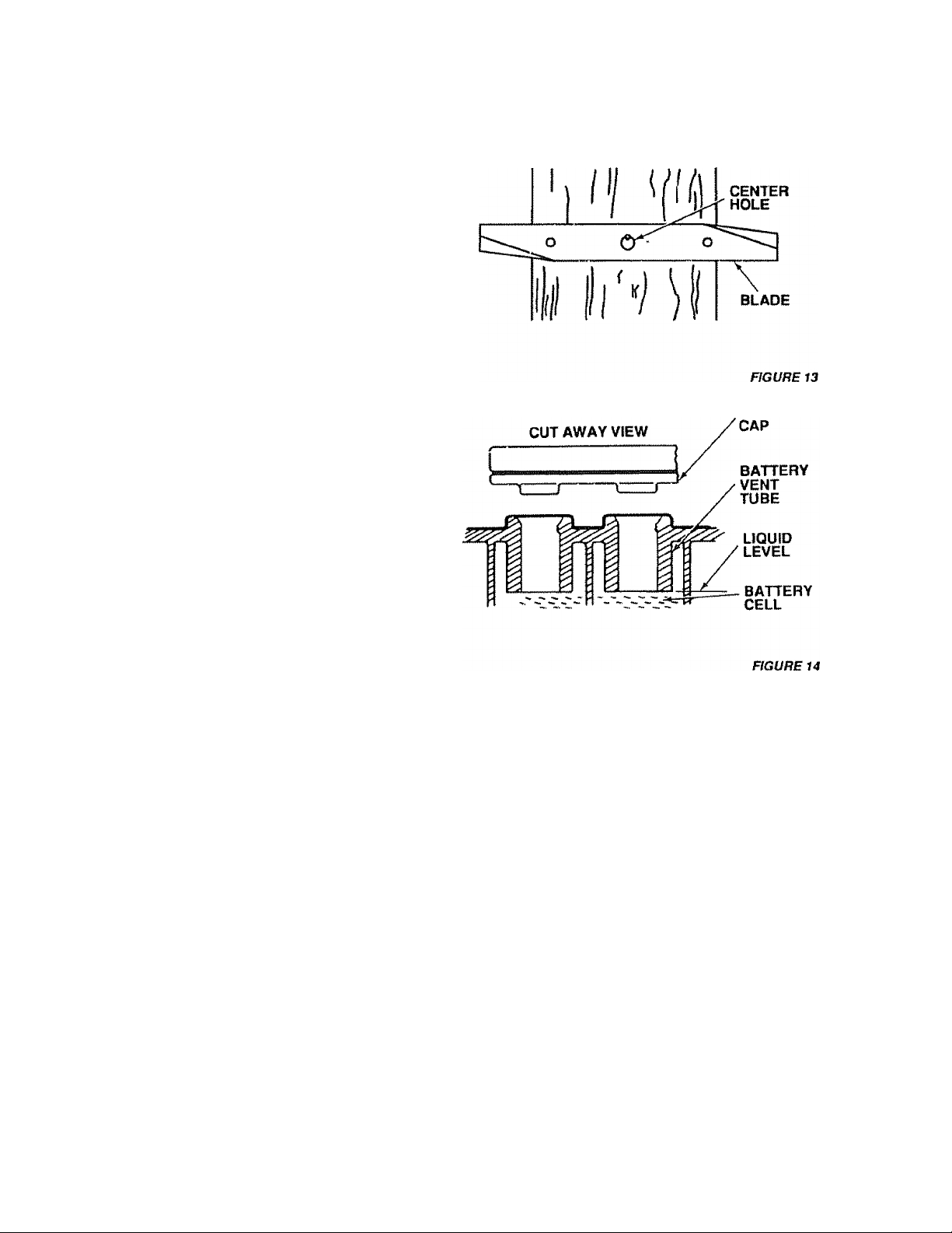
c. To check blade balance, drive a nail into a beam or
wall. Leave about one inch of the straight nail ex-
osed. Place center hole of clean blade over the
K
ead ot the nail (Fig. 13). NOTE: CENTER HOLE
OF BLADE ON NAIL. IF BLADE IS PROPERLY
BALANCED. BLADE SHOULD REMAIN IN POSI
TION SHOWN IN FIG. 13. IF EITHER END OF THE
BLADE MOVES DOWNWARD. BLADE IS NOT
BALANCED SHARPEN THE HEAVY END UNTIL
BLADE IS BALANCED
4. Battery Care
CHECK BATTERY
a. Battery acid solution level in each battery cell should
be even with bottoms of vent tubes in cells (Fig. 14)
Add ONLY distilled or iron free water if necessary.
NOTE: DO NOT OVERFILL,
b. Keep battery and terminals clean,
c Keep battery bolls tight,
d. Keep vent caps light and small vent holes in caps
open.
e. Recharge with auto battery charger.
REPAIR AND ADJUSTMENT
BATTERY
NOTE: OVERCHARGING WILL SHORTEN BATTERY
LIFE
CLEAN BATTERY AND TERMINALS
Corrosion and dirt on the battery and terminals cause the
battery to leak” power and hinders the operation of the
charger.
LEAD-ACID BATTERIES GENERATE
EXPLOSIVE GASES. KEEP SPARKS,
FLAME AND SMOKING MATERIALS
A
a Remove terminal guard
b. Disconnect BLACK battery cable, then RED battery
c Wash battery with lour tablespoons (6 grams) of
d. Rinse the battery with plain water, dry and reinstall
e Clean terminals and battery cable ends with wire
AWAY FROM BATTERIES. ALWAYS
SHIELD YOUR EYES AROUND BAT
TERIES.____________________________
cable, and remove battery from tractor
baking soda in one gallon (3.8 litres) of water.
NOTE: BECAREFULLNOTTOGETTHESODA
SOLUTION INTO THE CELLS
on tractor
bnjsh until bright
bie to negative terminal Coat terminal connections
with grease after installation of cables,
g Replace terminal guard
5. Change Engine Oil
The best time to change engine oil is at the end of a day's
operation when all dirt and foreign materiais are suspended
in the hot oil
Capacity is 1 quart (.94 litres). NOTE: DONOTOVERFILL.
Dipstick assembly must be securely tightened into tube at
ail times when engine is operating. 15
Page 16
REPAIR AND ADJUSTMENT
AIR
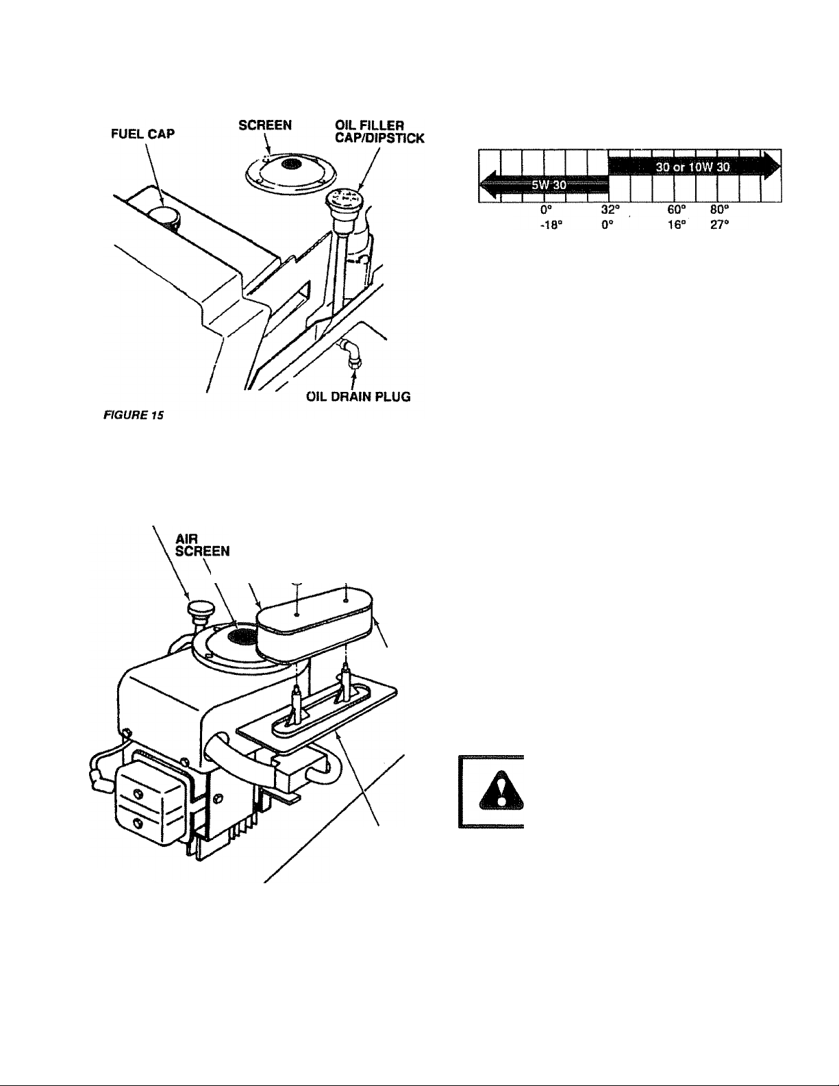
a Remove oil drain plug to drain engine oil. Tighten
plug securely before filling with fresh oil.
b Add oil through the oil filler cap/dipstick (Fig. 15).
RECOMMENDED SAE VISCOSITY GRADES
ENGINE OIL
FILLER CAP
AND DIPSTICK
AIR CLEANER
COVER
^CARTRIDGE j ^ rbER
‘ ‘ WASHERS
NUTS
FOAM
ELEMENT
T -20“
“C -29“
100“
38“
e. Check Engine Oil Level
NOTE: DO NOT CHECK ENGINE OIL LEVEL WITH EN
Several minutes after stopping engine, check engine oil
level with tractor on level ground. Wipe dipstick (Fig, 15)
clean, screw it down tight tor a few seconds, remove and
read oil level. If necessary, add oil until "FULL" mark is
reached (See chart above) NOTE: DO NOT OVERFILL.
GINE RUNNING
7. Clean Air Cleaner Element (Fig. 16)
a. Remove two wing nuts and remove air cleaner
cover.
b- Remove foam pre-deaner.
1. Wash prifr“Cleaner in liquid detergent and warm
water to rerrove dirt.
2. Wrap pre-cleaner in ctoth and squeeze dry.
3. Wipe foam with a light coat of engine oil. Do not
saturate. Squeeze in rag or towel to remove ex
cess oil.
c Remove two nuts from lop of cartridge,
d Remove cartridge and dean air deaner body care
fully to prevent dirt from entering carburetor.
e. Clean cartridge by gentiy tapping on flat surface. If
very dirty, replace cartridge.
f. Reassemble air cleaner.
NOTE: NUTS HOLDING AIR CLEANER CARTRIDGE
NOTE: NEVER RUN ENGINE WITH AIR CLEANER RE
MUST BE INSTALLED WITH FIBER WASHERS
DOWN ON CARTRIDGE PUTE TO PREVENT
DIRT FROM ENTERING CARBURETOR.
TIGHTEN NUTS BY HAND. OVER TIGHTENING
COULD COLLAPSE CARTRIDGE.
MOVED
AIR CLEANER
BODY
FIGURE 16
IMPORTANT: TO AVOID DAMAGE TO THE STARTING
SYSTEM. USE SAE 5W30 OIL WHEN
THE TEMPERATURE FALLS BELOW
32°F (0°C).
RECOMMENDED SAE VISCOSITY GRADES
Determine temperature range expected before next oil
change All oil must meet API, service classification SD, SE
or SR
8. Clean Air Cleaner and Engine Cooling Fins
ALWAYS WEAR EYE AND FACE PRO
TECTION WHEN USING COMPRESSED
AIR.
Air screen and cooling fins (Figs. 16 and 17} must be kept
free of dirt and chaff to prevent engine damage from over
heating. Clean with a wire brush or compressed air to re
move dirt and dried gum fibers,
Remove hood (page 20).
a.
Remove air deaner cover (Fig. 16).
b
c
Remove 3 screws securing air cleaner body (Fig.
17) and remove. (Covercarburetorto prevent entry
of dirt.)
Remove oil dipstick and cover opening to prevent
entry of dirt.
Remove 3 screws from blower housing and lift
housing off engine (Fig 17),
16
Page 17

REPAIR AND ADJUSTMENT
f. Use compressed air or stiff bristle brush to thor
oughly clean engine cooling fins (Fig, 17) and air
screen (Fig. 16).
g. To reassemble, reverse above procedure,
h. Be certain carburetor tube, breather tube, and gas
kets are in place (Fig. 17).
9. Check Muffler
Inspect and replace damaged nmjffler and/or deflector as it
could create a fire hazard and/or damage.
DO NOT TOUCH HOT MUFFLER, CYLIN
DER OR FINS AS CONTACT MAY
CAUSE BURNS.
10. Lubricate Pivot Points
Place several drops of SAE 30 oil at points where metal
parts move against each other, see Lubricatfon Chart page
24.
11. Starting Your Tractor With a Weak Battery
If your battery is too weak to start the engine, it should be re
charged. If "jumper cables” are used for emergency starting,
follow this procedure:
NOTE: YOUR TRACTOR IS EQUIPPED WITH A12 VOLT
NEGATIVE GROUNDED SYSTEM. THE OTHER
VEHICLE MUST ALSO BE A12 VOLT NEGATIVE
GROUNDED SYSTEM.
SCREW AIR
blowerX cover
HOUSING %
HEX HEAD
SCREW
COOLING
FINS
SPARK
PLUG
\ CLEANER
BREATHER
TUBE
MUFFLER
SCREWS
GASKET
Ncarburetor
xTUBE
CYLINDER
HEAD
COVER
FIGURE 17
LEAD-ACID BATTERIES GENERATE
EXPLOSIVE GASES. KEEP SPARKS.
FLAME AND SMOKING MATERIALS
A
AWAY FROM BATTERIES. ALWAYS
WEAR EYE PROTECTION WHEN
AROUND BATTERIES.
Connect each end ol the RED jumper cable to the
a.
POSITI VE(+) terminals of each battery (taking care
not to short against chassis) {Fig 18).
Connect one end of the BLACK jumper cable to the
b
NEGATIVE (“) terminal of fully chaiged battery.
Connect the other end of the BLACK jumper cable
to the L.H side panel bolt (Fig 19) NOTE: KEEP
AWAY FROM GAS TANK AND BATTERY,
Disconnect cables in reverse order:
d
1 L H side panel bolt (Fig 19)
2 Negative terminal of fully charged battery
3 Positive terminals
DO NOT USE YOUR TRACTOR BAT
A
TERY TO START OTHER VEHICLES
17
■DRIVE" POSITION
FIGURE 19
Page 18

REPAIR AND ADJUSTMENT
SCREW
FIGURE 20
12. Throttle Control Cable Adjustment
DO NOT MAKE UNNECESSARY AD
JUSTMENTS. FACTORY SETTINGS
ARE SATISFACTORY FOR MOST AP
A
PLICATIONS AND CONDITIONS. IF AD
JUSTMENTS ARE NEEDED, PROCEED
AS FOLLOWS:
a. Make sure air cleaner is clean (see page 16).
b. With engine not running, place Ihrottie control in
“FAST’position (not in ‘CHOKE" position).
CLAMP
c. Chedtthat holein throttle teverand hole in plate line
up {Fig. 20 “ Insert). If trales “A" are not aligned,
loosen clamp screw and move throttle cable until
holes are aligned. Tighten clamp screw.
d. If holes do not align, repeat steps in throttle cable
adjustment.
13. Carburetor Adjustment
NOTE: ADJUSTTHROTTLE CONTROL CABLE BEFORE
NOTE: THE SCREW SEAT MAY BE DAMAGED BY
MAKING ANY ADJUSTMENT TO CARBURETOR.
a. With engine off turn high speed mixture screw cfock-
wise closing finger tight ONLY, and turn counter
clockwise 1-1/2 turns.
TURNING IT TOO FAR CLOCKWISE.
b. Turn idle mixture screw clockwise closing finger
light only, and turn counterclockwise 1-1/2 turns.
REFER TO “STARTING THE ENGINE'
PAGE 11.
c. Start engine and allow to warm for five minutes.
Make final adjustment with engine running and gear
shift lever in "NEUTRAL" position.
d. With throttle control lever in "FAST position, turn
high speed mixture screw clockwise until engine
runs "rough" and then turn counterclockwise 3/4
turn.
e With throttle control lever in "SLOW" position, hjm
idle mixture screw counterclockwise until engine
runs "rough" and then turn clockwise until engine
begins to die. Turn idle mixture saew to a point mid
way between these positions.
f. With throttle control lever in "SLOW position en
gine should idle at 1700 RPM. If engine idles too
slow, push throttle control lever above idle and turn
idle speed screw one turn clockwise. Set throttle
control lever at "SLOW. Repeat until satisfactory
idle is attained.
g If engine idles too fast with throttle control lever in
"SLOW position push throttle control lever above
idle and turn idle speed screw one turn counter
clockwise. Set throttle control lever at "SLOW.
Repeat until satisfactory idle is attained.
h . High speed stop is factory adjusted . DO NOT AD
JUST - DAMAGE MAY RESULT,
14. Replace Spark Plug
Replace spark plug at the beginning of each mowing season
or every 100 hours, whichever comes first. Gap should be
set a 0.030 inch (Fig 21) .
15. Adjust Valves on Engine
After approximately 200 hours of operation, the engine
valves will require adjustment. It is suggested that a Sears
Service Center do this work. Correct settings are: Intake -
,002 (.05 mm). Exhaust - 004 (.1 mm).
16. Replace In-Line Fuel Filter
BE SURE THERE ARE NO FUEL LINE LEAKS AND THAT
HOSE CLAMPS ARE PROPERLY INSTALLED.
If fuel filter is clogged, obstructing fuel flow to carburetor, re
placement is required.
a With engine cool, remove filter and plug fuel line
sections that were removed from botn ends of fuel
filter (Fig. 20).
b. Place new fuel filter in position in fuel line.
18
Page 19

17. Motion Drive Beit Removal
Tile tractor drive ben maybe replaced wflthouttools. Park the
tradoron level area. Engage parking brake. NOTE: A BELT
INSTALUTION DECAL IS UNDER LEFT FOOTREST.
a Remove mower {See page 21),
b. Remove two retainer springs from belt guide
bracket below transaxle pulley Remove bracket
(Fig. 22).
c. Swing belt guides away from belt, toward rear of
tractor (Fig. 22).
d Roll bell over top of transaxte pulley.
e Roll belt over engine pulley and off idler (Fig 23).
I, Release parking brake. f^H belt as far as possible
over top of clutch pulley.
g. Reset parking brake. Pull belt over top of clutch pul
ley (Fig, 23).
h. Pull belt out through shift gate to remove from trac
tor (Fig 24)
i Install belt by reversing above procedure
REPLACE BELT ONLY WITH THE BELT
LISTED IN THE REPAIR PARTS SEC
A
TION OF THIS MANUAL.
18. Fuse Replacement
Replace with 30 amp automotive-type plug-in fuse The
fuse holder Is located under the dash
REPAIR AND ADJUSTMENT
FIGURE 22
ENGINE
19
FIGURE 23
Page 20

REPAIR AND ADJUSTMENT
GRASP ,
tJt^otr' ^
FiClMItM
HOOD
DASH
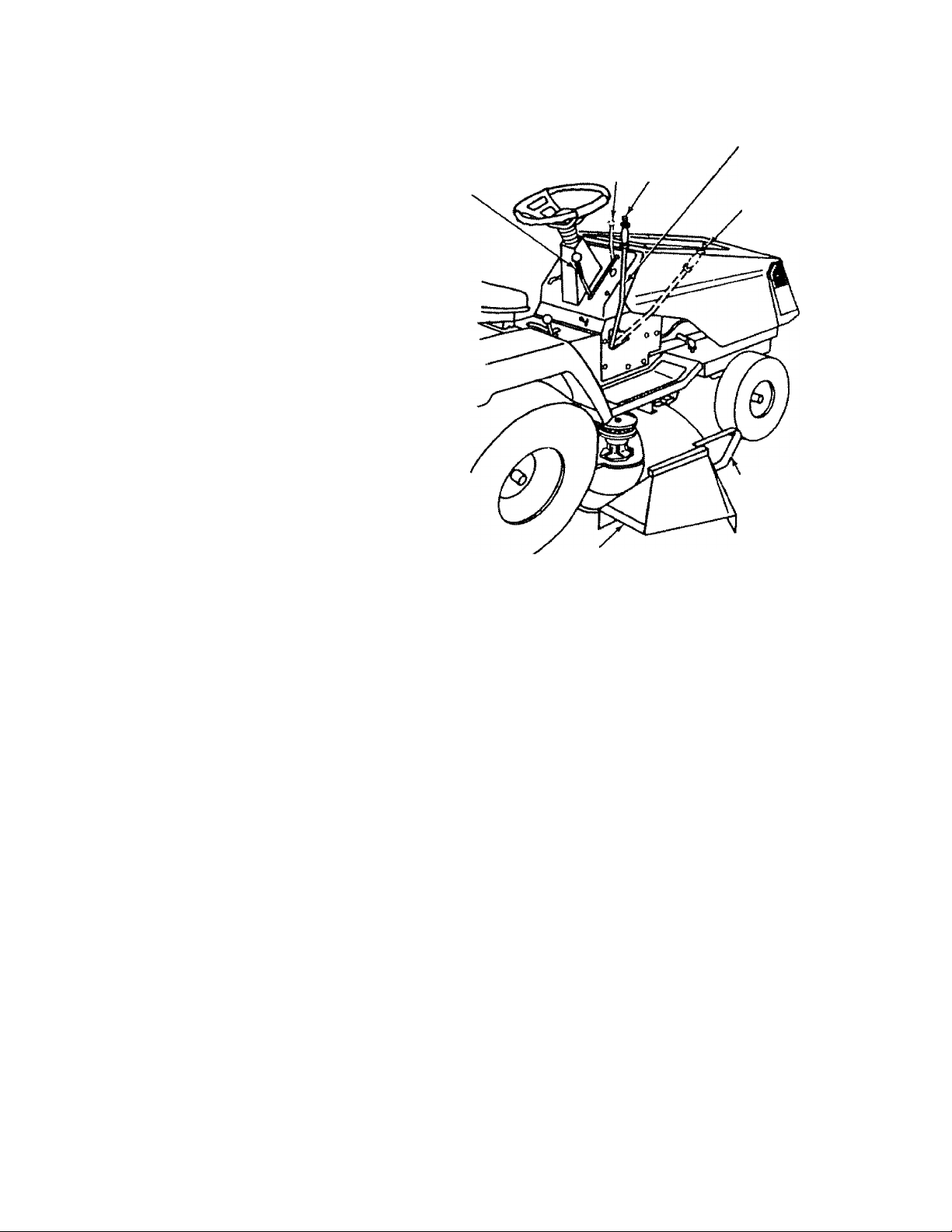
19. Hood Removal
KEEP FEET CLEAR FROM UNDER
A
A
MOWER DECK.
DO NOT TOUCH HOT MUFFLER, EN
GINE CYLINDER OR COOLING FINS
AS CONTACT MAY CAUSE BURN.
FIGURE 2S
HOOD
GRASP
HERE
HINGE
BRACKET
HOOD
SPRING
GRASP
ucoc
a. Grasp hood at edge next to dash afKl open hood to
full up position (Fig. 25).
b. Disconnect headlight connection (Fig. 28)
c Carefully remove hood springs from hinge brack
ets (Fig. 25).
SPRINGS ARE UNDER TENSION.
WEAR SAFETY GOGGLES DURING RE
A
20.
MOVAL AND INSTALLATION.
d Lower hood half way and grasp at the bottom of the
grill and at the upper hood edge (Fig . 26). Lilt hood
up, out and away from tractor,
e. Place hood carefully on the ground ,
Hood installation
a. Pick hood up at top of grill and upper hood edge
(Fig. 27),
b Align hood pivot rod with hinge brackets. Rotate
hood halt way down, slide pivot rod in and down
into hinge slots (Fig. 27).
Open hood to full up position (Fig. 25).
Carefully reinstall hood hinge springs (Fig 25).
Reconnect headlight connection.
Close hood.
HEADLIGHT
FIGURE 2S
GRASP
HERE
FIGURE 27
HINGE
BRACKET
SLOT
20
Page 21

21. Mower Romoval
a Remove mower belt per instructions under “Mower
Drive Beit Removal" through step (c).
b. Remove retainer spring from clutch rod; pull clutch
rod out of clutch bracket. (Fig. 29)
c. Pull retainer springs out of rear suspension trun
nions. Remove rear suspension trunnions from lift
brackets (Fig, 29).
d. Pull retainer spring out of rear hinge pin. Remove
rear hinge pin. (Fig. 29).
e Pull retainer spring out of front hinge pin Remove
front hinge pin (Fig. 29).
f Use lift leverto raise suspension arms Slide mower
out from under tractor
NOTE: IF AN ATTACHMENT OTHER THAN THE MOWER
DECK IS TO BE MOUNTED ON THE TRACTOR,
THE L H AND R.H. SUSPENSION ARMS (FIG.
29) SHOULD BE REMOVED FROM TRACTOR,
22. Mower Installation
Your Mower Installs without the use of tools Raise attach
ment lift lever (Fig 30) to its highest position.
a. Slide mower under tractor,discharge guard to R H
side-
fa Install front hinge pin through axle and parallel link
(Fig. 32). Secure with retainer spring.
c Install rear hinge pin through mower lift brackets
and parallel link (Fig 32) Secure with retainer
spring
d Install clutch rod in clutch lever (Fig 32).
e. Move attachment lift lever (Fig 30) forward to lower
suspension arms. Slide trunnions through lift
bracket holes and secure with retainer springs (Fig.
29).
f. Roll belt over engine pulley Make sure belt is inside
bell guides (Fig 32). See belt drive schematic decal
on mower housing
g. Use attachment lift lever (Fig 30) to raise mower
h. Push lift lever plunger down and position
attachment lift leverto desired cutting height (Fig
31). Release lift lever plunger
REPAIR AND ADJUSTMENT
RETAINER
SPRING
R H
SUSPENTION
RETAINER
SPRING
ENGINE
PULLEY
RETAINER
SPRINGS
Page 22

REPAIR AND ADJUSTMENT
BELT
EXTENSION
SPRING
L.H.
MANDREL
COTTER PIN
EXTENSION
SPRING
BRAKE
ROD
BOLT
L.H. PIVOT
BRACKET
FIGURE 33
LIFT
LEVER
ENGINE
PULLEY
IDLER BELT
GUIDE
ROCK SHAFT
ASSEMBLY
R.H. PIVOT
BRACKET
23. Mower Drive Belt Removal
NOTE: MOWER BELT INSTALLATION DECAL LOC
REPUCE ONLY WITH THE BELTS SPECIFIED IN THIS
MANUAL.
ATED ON MOWER HOUSING.
a. Place attachment clutch lever in "Disengaged” posi
tion (Fig 30).
Move Attachment lift lever {Fig 30) forward to lower
b.
mower to Us lowest position
Roll belt off engine pulley.
c.
Pull belt off both mower deck pulleys
d
Spring belt guide away from idler pulley and pull belt
e.
off idler pulley
f Slide belt from under extension spring
24. Mower Drive Belt Replacemertt
a Slide belt under extension spring (Fig, 33),
b Place bett on rear side of both mandrel puiieys
c Spring idler belt guide down and place belt around
rear side of idler pulley
d Roll belt over engine pulley
e. Make sure belt is inside all bell guides.
NOTE: WHEN INSTALLING A NEW BELT, EXTENSION
SPRING MUST BE RETURNED TO LOWER END
OF SLOT (ORIGINAL POSITION) ON ROCK
SHAFT ASSEMBLY.
25. Mower Drive Belt Adjustment
Your tractor has been manufactured with the ability to read
just the mower drive belt to provide you with longer belt life.
If the attachment clutch lever travels 4-1/2" (11.43 cm) up
the slot in the dash before spring resistance is evident ad^
iustment is necessary. NOTE: CHECK FOR PROPER
ipHING TENSION WITH THE ENGINE OFF AND THE
LIFT LEVER IN THE HIGHEST POSITION.
a Lower the mower deck for easier access
b Using (2) 7/16" wrenches, remove the bolt, nut & D-
Shaped washers (Fig 33 - inset).
c Move extension spring from lower end of slot to up
per end in rock shaft assembly and install bolt, nut &
the D-Shaped washers
d Tighten bolt and nut to secure the D-shaped wash
ers (flat side down).
26. Level Mower Housing
Adjust the mower while tractor is parked on level ground or
driveway. Make sure lire pressure is correct, if tires are over
or under infiated, you will rrot properly adjust your mower
FIGURE 34
FIGURE 3S
NUT"C”
NUT"B"
SIDE-TO-SIDE MOWER ADJUSTMENT
a Depress lift lever plunger and use lift lever to raise
mower to maximum cutting height {Fig. 31).
b. Measure height from bottom of curl to ground line at
front of mower. Distance "A" should be the same on
both sides (Fig. 34).
c. if distance “A” needs to be changed, snap out ac
cess hole cover on L.H. side above footrest Use
11/16” wrench on nuts "B” and "C" at side-to-side
adjustment trunnion (Fig. 35),
d To raise left side of mower, loosen nut “B" and
tighten nut “C"
e To lower left side of mower, loosen nut “C" and
tighten nut "B".
22
Page 23

REPAIR AND ADJUSTMENT
NOTE: ONE ROTATION OF ADJUSTMENT NUTS IS
FRONT-TO-REAR MOWER ADJUSTMENT
NOTE: MEASURE DISTANCE “D” FROM GROUND LINE
NOTE: WHEN ADJUSTING REAR SUSPENSION TRUN
EQUIVALENT TO APPROXIMATELY 3/16* (4.75
mm) HEIGHT CHANGE.
L Be sure all rwls are securely tightened.
g. Replace cover.
a. To obtainihe best cutting results, your mower hous
ing should be adjusted so the front and rear flange
distance "D" (Fig. 36) is 1/2’ (1.27 cm) lower in front
when the mower is positioned in the highest cutting
position.
TO BOTTOM OF CURL ON RIGHT REAR
FLANGE AND COMPARE TO DISTANCE’D’ AT
BOTTOM OF CURL ON RIGHT FRONT FLANGE.
b. To raise rear of mower, loosen nut “E" on both rear
suspension arms. Screw both nuts “P up EQUAL
NUMBER OF TURNS (Fig 37).
c. When distance "D* is 1/2" (1.27 cm) lower at front
than rear lighten nuts “E"
d. To lower rear of mower, loosen nut "P on both rear
suspension arms an EQUAL NUMBER OF TURNS
(Fig. 37).
e. When distance “D" is 1/2" (1.27 cm) tower at front
than rear, retighten nuts “E”.
NIONS. ALWAYS ADJUST BOTH EQUALLY SO
MOWER WILL STAY LEVEL.
27. Storage
Remove mowerfromlractorfor winter storage. When mow
er Is to be stored for a period of time, clean it thoroughly, re
move all dirt, grease, leaves, etc. Give blades and uriderside
of fwusing a good coat of grease or rust preventative. Store
in a clean dry area.
A. Fuel System
R is important to prevent gum deposits from forming in es
sential fuel system parts such as the carburetor, fuel filter,
fuel hose, ortank during storage. Also, experience indicates
that alcohol blendedfuels (called gasohoior using ethanol or
methanol) can attract moisture which leads to separation
and formation of acids during storage Acidic gas can dam
age the fuel system of an engine while in storage. To avoid
engine problems, the fuel system should be emptied before
storage of 30 days or longer.
B. Engine OH
Drain (with engine warm) and replace with clean engine oil,
(See chart page 16).
C. Cylinder
Remove spark plug.
1.
Pour one ounce (29.5 ml) of oil through spark plug
2.
hole in to cylinder.
Turn Ignition key to "START" position for a few sec
3.
onds to distritxjte oil.
Replace with new spark plug.
TRUNNION
NUT"E"
REAR
SUSPENSION
TRUNNION
NUT "F"
D. Battery
LEAD-ACID BATTERIES GENERATE
EXPLOSIVE GASES. KEEP SPARKS.
FLAME AND SMOKING MATERIALS
A.
E. General Cleaning
AWAY FROM BATTERIES. ALWAYS
WEAR EYE PROTECTION WHEN
AROUND BATTERIES.
1. Prior to storage, clean terminals and top of
battery
2. Disconnect BLACK battery cable from
negative side of battery.
3 Disconnect RED battery cable from positive
side of battery.
4. Position cables down and away from battery,
Clean engine, battery, seat, finish, etc of ail foreign matter.
REAR
SUSPENSION
FIGURE 36
OCT AO
ItCArf
SUSPENSION
ARM
LIFT
Kl O ACI'T
O’riiM I
HGURE37
23
Page 24

REPAIR AND ADJUSTMENT
LUBRICATION CHART
©SiEMHOTOHOIL
0 GENERAL PURPOSE GREASE
REFER TO PAGE 16 FOR
©
ENGINE OIL SPECIFICATIONS
24
Page 25

PROBLEM
WILL NOT START
WILL NOT TURN OVER
ENGINE CUCKS BUT WON’T START
HARD TO START
ENGINE MISSES OR LACKS POWER
ENGINE OVERHEATS
TROUBLE SHOOTING
19*
Push Clutch/Bfake Pedal into Brake positton
Move Attachment Clutch Lover to "Disengaged* positton
IST'
Fill Tank wHh Gasoline. Check Fuel Line and Carburetor (dean if
necessary). Replace Fuel Rlter. Use Fresh Fuel
Check Fuse for fault and replace
«r
Recharge or replace Battery
Check Wiring
Replace Spark Plug(s) and adjust gap
m“
Adjust Valves
m
Push Clutch/Brake Pedal into brake position
tr
Charge or replace Battery
W'
Move Mower Clutch Lever to “DISENGAGED" position
Replace Ignition Switch
w-
Replace Interlock Switch(es)
tet
Replace Solenoid or Starter
mr
Check for fault and replace Fuse
m-
Check all Wire Connections and “Ground" Points
mt
Clean Battery Terminals
№'
Replace Starter or Solenoid
mt
Charge or Replace Battery
m
Chedt Wire Connectbns and “Ground” Points
m-
Place Throttle Control in “FAST” position and run starter several times
to clear out gas
cSP
Remove Air Filter and clean
■I-
Replace Spark Plug(s) and afjust gap
*s*
Recharge or replace Battery
1®*
Check the Wiring
lar
Drain Fuel Tank and Carburetor. Use Fresh Fuel Replace Fuel Filter
w
Make necessary adjustments to Carburetor
ar
Adjust Valves
ar
Major Engine Overhaul
Shift to a lower gear or reduce toad
19"
Drain Gas Tank and Carburetor, Use Fresh Fuel
19'
Remove and clean Air Cleaner
IT
Make necessary Carburetor adjustments
«r
Clean Air Screen
Add or change oil
19'
Replace Spark Plug(s) and adjust gap
<at
Check for loose wires
m-'
Replace Fuel Filter
nt
Adjust Valves
m
Major Engine Overhaul
mt
Shift to lower gear or reduce load
mt
Clean Air Saoen
19-
Add or change oil
m-
Clean Engine Cooling Fins
m-
Remove and clean Muffler or replace
Mr
Remove and clean Air Filter
25
Page 26

TROUBLE SHOOTING
NOUGH1B
WONT CHARGE
ENGINE WILL NOT SHUT DOWN
WHEN OPERATOR LEAVES SEAT
UNSATISFACTORY MOWER PERFORÎWANCE
UNEVEN DISTRIBUTION OF CUPPINGS
MOWER BLADES WILL NOT ROTATE
EXCESSIVE MOWER VIBRATION
WINDROWING STRIPPING OH
DROPPING OF GRASS CUPPINGS
UNEVEN CUT OR SCALPING
m-
Use fresh fuel and adjust Carburetor
m
Drän and replace oil for proper temperature
isr
Check Fuse, Switch and Wire Connections. Replace Headlight Bulbs
«r
Replace Switch
cr
Check Fuse for fault and replace
m
Replace Battery
Replace Regulator
Replace Altarnator
NOTE: Ibis tractor is equipped with an operator presence sensing
system. Any attempt by the operator to leave the seat with the engine
running and the mower clutch engaged will shut down the engine.
Check all Wire connections
mt
Check Seat Switch
m-
Chedc Operator Presence Relay
tsr
Place Throttle Control in “FAST position
Check air pressure in Tires
m-
Check front-to-rear and side-to-side Mower adjustment
«r
Use a sbwer ground speed
Replace Mower Blades
mt
Reinstall Mower Blades with Sharp Edge down
Replace with proper Mower Blades
vsr
Readjust Mower Drive Belt
m-
Clean underside of Mower Deck
Correct Clutch mechanism Interference
Install new Mower Drive Belt
XSt
Adjust Mower Drive Belt
fiSr
Replace frozen Mandrel
fSBf
Replace frozen Idler Pulley
m-
Replace bent or unbalanced Blades
ifflr
Replace Mandrel, Replace Deck
«0^
Set Throttle for maximum engine speed
m-
Let grass dry out
for
Clean underside of Mower Deck
w
Readjust Mower front-to-rear and side-to-side
m-
Replace Blades
BT
Readjust Mower front-to-rear and side-to-side
sst
Replace Blades
Ifflr
Replace bent Mandreljs}
26
Page 27

12 HP 38"
SCHEMATIC
mmm
lawn tractor - - model number d17.254611
№0
1ZV
“1“
O|lI I o
SLACK
FUSE
30 AMP
RED
WHiTi
lOTERLOCK SWITCHES
CLUTCH? BRAKE (aUTCHOFF)
(TOALUP)
ATTMENT CLUTCH
I RED
o
BUCK
IGNITION SWITCH
POSITION
OFF
ON
START
aRCurr
B-S
WIRING INSULATED CURS
NOTE: IF WIRING INSULATED CLIPS
OR CABLETIES WERE REMOVED FOR
SERVICING OF UNIT. THEY SHOULD
BE REPLACED TO PROPERLY SE
CURE YOUR WIRING.
NON-REMOVABLE CONNECTIONS
-O- REMOVABLE CONNECTIONS
3 AMPS DC
AT 3600 RPI«L BATTERY IN LINE
CnANGE
U6HT
SWITCH
YOUR TRACTOR IS EQUIPPED WITH A
SPECIAL ALTERNATOR SYSTEM. THE
LIGHTS ARE NOTCONNECTEDTOTHE
BATTERY, BUT HAVE THEIR OWN
ELECTRICAL SOURCE. BECAUSE OF
THIS,THE BRIGHTNESS OFTHE UGHTS
WILL CHANGE WITH THE ENGINE
SPEED. AT IDLE SPEED, THE LIGHTS
WILLDIM. ASTHEENGINEISSPEEDED
UP, THE LIGHTS WILL BECOME THEIR
BRIGHTEST.
27
CHAKIS
GROIJND
Page 28

REPAIR PARTS
12 HP 38" RIDING LAWN TRACTOR - • MODEL NUMBER 917.254511
ELECTRICAL
U
Page 29

REPAIR PARTS
12 HP 38” RIDING LAWN TRACTOR - - MODEL NUMBER 917.254611
ELECTRICAL
IS9
iO
KEY
NO. NO.
1
PART
7662J
2 124108X
3 126399X
4
5
6
7
8
9
10
11
12
13
14 STD541425
15 108423X
16
17
18
19
20
21
22 STDS51025
23
24
25
26
27
10931OX Key. Molded
110712X
104446X
7603J
109596X
STD365402 • Switch, Ignition
108824X
STDS51125
STD541225
STD5^50S
11050400
719J
5114J
109553X
4207J
STD522507
STD541025
121265X
102476X
123198X
STD551125
DESCRIPTION
Bulb, Light
Harness, Light Socket
Harness, Wiring
Switch, Light
Switch, Interlock
Tray, Battery
Clamp, Hose
Fuse. 30 Amp
* Washer, Lock, 1/4
• Nut. Hex Jam 1/4 20
. Bolt, Hex, 1/4 20 X 1/2 Gr, 5
• Nut. Keps 1/4 20
Cable Assembly
Washer Lock. Ext. Tooth, 1/4
Cover, Terminal
Cable, Battery
Switch, interlock
Cable, Batterv
• Bolt, Hex. 1/4 20 X 3/4
• Washer 9/32 x 5/8 x 16 Ga.
• Nut, Hex 1/4-20
Battery, 12V„ 25 Amp
Terminal Guard
Wing Nut 1/4-20
• Washer, Lock Hvy Helical Spring
KEY
NO.
28 72240460 Bolt Rd. Hd. Sq. Nk. 1/4 20 x
29
30
31 109788X Nut, Ignition
32 7192J Cable Tie
33
34 121305X
35
36 74641008
37
38
39
41 11150400 Lockwasher 1/4 Internal Tooth
—
—
NOTE: All component dimensions given in U.S. inches,
PART
NO.
10908IX
109787X
105687X
STD601005
73951000 Nut Keps No. 10-32 x 1/2
4171H Clip Insulated
121264X
101539X
126795X
1 inch » 25.4 mm.
•STANDARD HARDWARE -PURCHASE LOCALLY
DESCRIPTION
7-1/12
Solenoid
Bezel ' ignition
Tube, Plastic
Switch, Plunger
• Screw,Tap Hex Hd. #10 x 24 UNO
Screw - Slotted Pan Hd. No, 10-32 x
1/2
Battery Caps Set
Sheet, Instruction, Tractor, 15®
Owner’s Manual
Page 30

REPAIR PARTS
12 HP 38” RIDING LAWN TRACTOR - - MODEL NUMBER 917.254611
40
Page 31

REPAIR PARTS
12 HP 38" RIDING LAWN TRACTOR - - MODEL NUMBER 917.254611
CHASSIS
KEY
NO. NO.
1
2 17430612 Screw. Hex Washer ThcJ. Roll
3 17490616
4
5
6 73680500
7
8
9
10
11
12
13
14
u
15
16
!7
IS STDSS1125
20
21 19131312
22
24
25
26
27
29
30
31
32
33 121248X
34
PART DESCRIPTION
121075X
105513X
106529X
124181X
109872X
STD523707
Seat
3/8 16 X 3/4
Screw, Hex Washer Thd. flotling
3/6 16 1
Bracket-Pivol. Seal
Soft. Shoulder, 5'16 18
Nul Crownlock 5i16 18
Spring. Seat
Fender
* Bolt. Fin Hex 3/8x16 UNO x 3/4
17030808 Screw, Spiderlock Hex #8 x 1/2 AB
73680600
17490608
109873X Bracket, Fender
STDS12505
10S465X
Nut, Crownlock 3'8 16
Screw. Hex Washer Thd Roll 3 8
16x12
• Bolt, Fin Hex 1/4 x 20 UNC x 1/2
Footrest. L H
105464X Footrest. R.H
STD533707
• Bah, RdHdSqNk 3/8 x 16 UNC x 3/4
• Washer. Lock, Hvy Helical Spring
STD523710
•Bolt. Fin Hex 3/8x16UNCx1
Washer 13/32 x 13/16 x 12 Ga.
124029X
19131210
124238X
105466X
Lens Assembly
Washer 13 32 x 3'4 x 10 Ga
Cap, Spring
Pad, Footrest
124493X Decal, 12 HP
122933X Rivot, Ratchet, Nylon
124027X
Shield, Hcx>d, Heat
123665X Deflector, Heat
124025X
STD541437
Hood Assembly
Bushing. Snap
• Nut. Crownlock 3/8x16 UNC
KEY
PART
NO. NO.
35
36
37
3B
39
40
41
42
43
44
45
46
47
48
49
50 123976X
51
52
53
54
55
56 124490X
57
58
59
60
61
62
124479X
124355X
121306X
124294X
125880X
124492X
4900J
105809X
109199X
19132012
121440X
121441X
2751R
19131614
72170410
121251X
121250X Spring, Seat, Compression
121249X
121246X
124489X
123913X
123914X
124040X
123915X
105037X
121144X
63 STD525010
64
65
66
19171912
106974X Decal, Caution
750211
67 STD551150
DESCRIPTION •
Washer, Black, Nylon
Chassis Assembly
Drawbar
Pan . Seat
Decal Fender
Decal. Grill, Craftsman
Decal, Clutch/Brake
Deca), Chassis, S Spaed, 38*
Decal, V-Belt Ground Drive
Washer 13/32 x M/4 x 12 Ga.
Guide Belt. Lower. Eng. Pulley, L.H.
Guide Belt, Lower, Eng. Pulley. R.H
Clip
Washer 13/32 x 1 x 14 Ga-
BoN.RdHd 1/4x20x1-1/4
Nut, Hex, Lg., Flange, Loc.
Strip. Foam
spacer. Split
Bracket, Switch Mount
Decal Strioe Hood L.H.
Oecai Stripe Hood R.H,
Bracket, Rvot, R.H.
Bracket, Pivot, L.H.
Spring, Extension
Grill
Foam, Strip 18
Boh. Shoulder
• Boh, Fin Hex 1/2 -13 UNC x 1 Gr. 5
Washer 17/32 x 1-3/16 x 12 Ga.
Decal, USA
* Washer, Lock Hvy. Helical Spring
B c
□ 5 J 9
® <S> 24
©6
10
(5^19
14
1 inch = 25.4 mm.
•STANDARD HARDWARE PURCHASE LOCALLY
L
® 44
® 11
|49
® 50
12
© 21
©11
62
Page 32

REPAIR PARTS
12 HP 38" RIDING LAWN TRACTOR ■■ - MODEL NUMBER 917.254611
DRIVE
/8515/^35 4
?'i|^77 27 3^\\y I
----------------
^36
.-O' -i
2 / 57
88
OPTIONAL EQUtPMINT
Spark Arresier
32
Page 33

REPAIR PARTS
12 HP 38” RIDING LAWN TRACTOR - - MODEL NUMBER 9.17.254611
DRIVE
KEV PART
W NO.
1
126126X
*
2
10S731X
3
13200300
4
STD551143
5
74770720
6
12S907X
7
12298ЭХ
8
2949R Gasket
9 101326L
10
12
12352вХ
STD551131
12121BX
STD551031
17490620
73680500
123666X
STD523710
17490512
108171X
123662X
4921H
STD523107
11
13
14
15 STD5S1125
16 122372X
17 STD523727
18 STD541437
19
20
21 12000028
22 109167X
23
24
25
26
27
28 10ei90X
29
30 STD541437
31
123770X
32
123663X
33
34 121748X
35 Ш6933Х
STD523707
36 124379X
37 71040412
38 105701X
39
40 19151216
41 104777X
42
43
44 105730X
45
46
47
STD561210
17490612
19131312
10Э070Х
4470J Spacer
123674X
A В
DESCRIPTION
Engine, 12 HP, Tecumseh, Model
Number 143,408152
Pulley, Eneine
Elbow' STD 90 3/8 -18 NPT
* Washer, Lock, Hvy Helical Spring
Bolt. Нек 7/16 20 к М/4
V Belt. Drive
Muffler
Deflector, Muffler
Screw, Hex Head Cap
•Washer- Lock 5/16
Keeper, Belt, Engine
Washer 11/32x11/16x16Ga.
Screw, Hex Washer Thd Rolling
3/8x 16xM/2
• Washer,Lock, Hvy. Helical Spring
Transaxle, Tecumseh 5 Speed,
143,920037 (See pages 40 and 41)
• Bolt. Нек 3/8 16 X 2 3/4
•Nut, Crownlock 3/8 16
Nut, Crownlock 5/16 X 18
Pulley, Transaxle
Ring, Retainer
Bracket Transaxie
• Boil Hex 3/8 16 X 1
Screw. Hex Washer Thread Rolling
5/16-18 X 3/4
Support. Battery
Keeper 8eit. L H
Retainer Spring
Clamp
* Soil- Hex 5/16 18 X 3/4
• Nut, Crownlock 5/16 X 16
Strap Locator
Keeper Belt. R H
• Boll, Hex 3/8-16 X 3/4
Washer 25/32 x 1 5/8 x 16 Ga
Knob Shift
Rod Shift
Bolt Hex 1/4-28 X 3/4
Washer Shift Plate
* Cotter Pin, 1/8x1
Washer 15/32 x 3/4 x 16 Ga
Retainer Belt
Screw, Hex Washer Thd Rolling 3/B
16x3/4
Washer 13/32 x 13/16 x 12 Ga
Keeper, Bell. Engine
Retainer Belt
Idler Flat
C D E F
KEY PART DESCRIPTION
NO.
NO
48
123766X
49
123789X
50
STD523715 ' Bolt. Hex 3/B 16x11.2
51
105709X
52
110B12X
53
12000039
54
105710X Link, Clutch
STD561210 .
55
56
123102X Bracket. Clutch
57 110437X
58
106888X Spring, Rod, Brake
59
73350600
60
19131316
61
12563BX
62 1242Э6Х Cap Plunger
63
122424X
64
8883R
66 121749X
66
STD571810 ’
67
120183X Bearing, Nylon
68
123583X
69
13280324
70
59192 Cap Valve
71
65139
72
3588R
73
106108X
74
109501X
2751R
75
76
12000001
77
121520X
78
STD533707 ’
79
110422X
80
105706X Bearing
81
123205X Retainer Beh
82
17030808
83
105700X
84
108843X
85
19091210
86
11050600
87
7152J
88
121851X
89
STD551062 •
74760540
90
91 104757X
92
STD58002S •
93
126629X
94
STD541437 *
95
*—
•STANDARD HARDWARE PURCHASE LOCALLY
NOTE: All component dimensions given in U S inches
1 inch = 25.4 mm.
H
a к
Pulley, Idler
Arm, Idler
Spring, Return. Clutch
Washer Hardened
Ring Klip '
Pin Cotter 1/8x34
Rod Brake
Nut Jam 3/8 16
Washer 13/32 x 13 16 x 16 Ga
Rod Brake, Parking
Shaft Foot Pedal
Cover Pedal
Washer 25/32 x 1 1 4 x 16 Ga
■ Pm. Roll 3/16 X 1
Key, Square, 2.5 x ,1845/. 1865
Nipple. Pipe 3/8 NPT 3"
Stem, Valve
Tire, Rear
Rim Assembly, B", Rear
Spacer
Clip, Fuel Line
E Ring
Strap, Torque Transaxle
Bolt. Carnage 3/8 16 x 3/4
Spring Brake
Screw Spider Lock No 8-18
X 1/2 ABTPS
Spring
Plate. Shift
Washer 9/32 x 3/4 x 10 Ga
Washer Lock Ext Tooth 3/8
Tube Tire (not lurmshed with tractor)
Spark Arrester
Washer 21/32 x 1 x 16 Ga.
Boh, Hex 5/16x16x2-1/2
Cap, Hub
Key, Woodruff #9 3/16x3/4
Decal, Craftsman/Teoumseh 12 HP
Nut, Lock Hex w/wsh ins 3/8-16
See Key No. 72, Page 43
L M
33 '^42 *^78
®tei^3^43 @11
®18
33
Page 34

REPAIR PARTS
12 HP 38" RIDING LAWN TRACTOR - - MODEL NUMBER 917.254611
STEERING AND FRONT AXLE
Page 35

REPAIR PARTS
12 HP 38" RIDING LAWN TRACTOR - - MODEL NUMBER 917.254611
STEERING AND FRONT AXLE
27
28
29
30
31
32
33
34
11
12
13
14
15
16
1 7
18
19
20
21
22
23
24
25
26
KEY
NO
I
2
3
4
5
6
7
8
9
10
PART
OESCRiPTION KEY
NO
123042X012
74180512
73510500
109816X
124434X
17720410
Dash
Screw Truss Hd 5/16 18 x 3/4
Nut Keps 5/16 IB
Nyilner, Snap In
Control Throttle
Screw, Hex Thread Cut
1/4 X 20 X 5/8
126684X
124417X
WasherS/8x 1/4x16 Ga,
Bcxjt, Steering Shaft
124466X011 Saddle
17490608
2751R
125879X
100710L
STDS41350
100712K
100713N
10071IL
STD551125
71070410
124030X
5479J
STD611005
108456X
124373X
124036X
17490612
6266H
124034X
124035X
12000029
57079
124038X
122819X
104757X
Screw Hex Washer Hd Thread
RoNtng 3'8 16 X 1 2
Clip Insulated
Decal Steering Wheel Cap
Insert Steering Wheel
• Nut Hex Jam Lock 1 2 20
Washer 2-1/4
Wheel Steering
Adapter Steering Wheel
• Lockwasher 1/4
Screw, Socket Hex 1/4 x 20 x 5/8
Bumper, Hood
Plug, Button
• Screw Hex Sell Tap No
10 16 X t 2 Type ABTPS
Decal Instruction uperatmg
Bushing Steering
Bracket Steering
Screw Hex Washer Thread Rolling
3 8 16 x 3 4 Type TT
Bearing Thrust
Gear Sector 65
Shaft, Support
Klip Ring
Washer. Hardened
Shaft, Steering, Lower
Screw, Special
Cap, Hub
64
66
68
69
59
60
61
63
43
44
45
46
47
48
49
50
51
52
53
54
55
56
57
50
NO
36
37
38
39
40
41
42
NO
124033X
105663X
105664X
74761060
10566ЭХ
110438X
73901000
17490508
124037X
3366R
PART
Ю5715Х
120754X
19131416
76020412
STD5S1137
73610600
124032X
105656X
Ю5654Х
278H
9040H
106732X
59192
65139
106222X
121/4ЭХ
59904
121748X
STD551231
110307X
19272016
121232X
•STANDARD HARDWARE PURCHASE LOCALLY
DESOilPTfON
Shaft, Pitman
Support Saddle Rear
Support Saddle. Front
Bolt Нек 5,'8 1 1 к 3 3 4
A*ie Front
Spacer Bearing Front Axle
Nut Lock Flange 5 8 11
Screw Hex Washer Thread Rolling
51618x12 Tvpe TT ■
Gear, Piniori
Bearing
Rod Tie
Bushing
Washer 13 32 x 7 8 « 16 Ga
F'o Cotter 18x34
* Washer Lock 3 8
Nut, Fin Hex 3/8 X 24 UNF
Link Drag
Spindle L H
Spindle R H
Fitting Grease
Bearing Flange
Rim 6 Front (Inc 2 Each Key
No 561
Cap Valve
Stem Valve
Tire, Front
Washer 25 32 x I 1 4 x 16 Ga
Tube Front tNot furnished with
tractor)
Washer 25/32 x 1-5/8 X 16 Ga,,
* Washer Lock, Int Tooth 5 16
Stop, Mower Clutch
Washer 27 32 x 1 i 4 x 16 Ga
Gap, Spindle
NOTE: Ail component dimensions given in U,S. inches
1 inch t= 25,4 mm.
A В C 0
f 2 ? 6 f 33 ^10
®3
35
О О о
F G H
'Г26 ¥43 I 2
i В
О 65
® 3
Page 36

REPAIR PARTS
12 HP 38" RIDING LAWN TRACTOR»
LIFT ADJUSTMENT
MODEL NUMBER 917.254611
20
20
36
Page 37

REPAIR PARTS
12 HP 38" RIDING LAWN TRACTOR - - MODEL NUMBER 917.254611
LIFT ADJUSTMENT
29
30
31
24
25
26
27
28
20
21
22
23
Kiv
NO
10
11
12
13
14
15
16
17
18
19
PART
DESCRIPTION
NO
1
124429X Handle Ctuich Mower
2
106932X
3
10645IX
4
73680600
5
106452X
6
19171516
7
17021008
a
106447X
9
123549X
109202X
101335K
124026X
123487X
17490612 Screw, Hex Washer Thd Rolling
19091416
122795X
121794X
124031X012
19211416
STD5B1062
122365X
122512X
17490412
105736X
53208
120183X
105839X
105836X
STD551025
122507X
105751X
Knob
Bolt Shoulder
Nui, Crownlock 3/S 16
Bracket Switch Interlock
Washer 17/32 x 15/16 x 16 Ga.
Screw He* Tapping No 10 24
1 2 ■
Support Lever Clutch
Cap Fuel
Tank Fuel
Line Fuel
Grommet
Clamp Hose
3/8 X 16 X 3/4
Washer 9/32 x 7/8 x 16 Ga
Panel Dash L H
Cover Access
Panel Dash R H
Washer 21/32 x 7/8 x 16 Ga.
• E Ring
Button, Plunger
Spring, Compression
Screw, Hex Washer Thd Rolling
1/4 -20 X 3/4
Shield, Heat
Clip, Insulated
Bearing, Nylon
Receptacle, 1/4 Turn
Retainer, 1/4 Turn
• Washer 9/32 x 5/8 x 16 Ga
Shalt Lilt
Slud, 1/4 Turn
KEYNOPART
DESCRIPTION
NO
32
33
34
35 11Q029X
36 110447X
37
3B
39
40
41
42
43
44
45 4921H
46 I05864X
47
48
49 109728X
50
51
52
53
54
55
56
57
59
60
61
62
122364X
125631X
4939M
n0448X
121598X
105848X
121599X
106308X
STD541050
9135R
19171516
106444X
STD523707
STD561210
124444X
19131410
122514X
105767X
124446X
72140606
108236X
110739X
73980600
73360700
73710700
•STANDARD HARDWARE PURCHASE LOCALLY
Plunger
Grip Handle
Retainer Srpmg
Link LitS
Trunnion Lift
Link Liit Adiustable
Arm Suspension R H
Bolt Shoulder 3 8 16
Arm Suspension L H
Trunnion Lift Lower
* Nut Hex 12 13
Retainer Spring
Washer 17 32 X 15 16 * 16 Ga
Retainer Spring
Bracket Suspension
Bracket Belicrank
■ Bolt Hex 3 8 16 * 3 4
Belicrank Assembly
• Pin Colter 18*34
Rod Cl rich. Primary
Washer 1 3 32 * 7 8 * 10 Ga
Pod Assembly Lever
Pin Groove
Spring Extension
Screw 3 6 16x34
Bracket Switch
Washer Spring
Nut Flangelock 3 8 16
Not Hex Jam 7 16 20
Nut Crownlock 7 16 20
NOTE: All component dimensions gwen in U.S„ inches.
1 inch = 25,4 mm„
56
f se f ^ f
® 4
8
14 n 39 y 48
(0)59 @4
60
23
37
Page 38

REPAIR PARTS
12 HP 38" RIDING LAWN TRACTOR
38” MOWER
- MODEL NUMBER 917.254611
38
Page 39

REPAIR PARTS
12 HP 38” RIDING LAWN TRACTOR - - MODEL NUMBER 917.254611
38” MOWER
PART
KEY
NO
NO
DESCRIPTION
KEY
NO
PART
NO
DESCRIPTION
t
2
3
4
5
e
7
В 110452X
9 106734X Spritig, Deflector
10
11
12 105814X
13 105304X
14
15 105744X
16 105B72X Stop, Link
17
18
19 73680500
20 109598X
21 10Э597Х
22
23
24 10Í603X Support. Arm
25 109504X
26
27
28 74760632
29 1235S3X Arm, Idler
Э0 106902X
31 '21Э16Х
32 106513X
33 102в69Х
34 121в87Х
35 1006681
36
37
106085X V-Belt
121259X Housing
8417J Runner, R H
73680600
19111216 Washer 11/32 * 3/4 X 16 Ga
72140605
10589вХ
106735X
106736X
loseeax
109835X
STD523707
STD533107
3713J Decal, Instruction Caution
_ _ _
126756X
17490614
17490620
Nut, Crownlock 3/8 16
Bolt, Carr., 5/16 18 X 5/8
Bracket. Dellector
Puahnut
Rod • Hinge
Dellector Shield
Oecai, V Bel! Mower Drive
Cep
Link Parallei
Pin Hinge. Front
Pin Hinge. Rear
• Bolt 3/8 16 X 3/4
Nut. Crownlock 5/16 18
Bracket Lift R H
Bracket. Lift. L.H
• Bolt Ca rr 5/16 18 x 3/4
Stop, Deck. Front
Decal Safety Standard Not Serviced
Guide Beit
Boll 3/8 16x2
Spacer Retainer
Pulley idler
Washer. Wear 1/16
Keeper. Belt
Mandrel Assembly
Plate. Support Mandrel
Screw. Hex Washer Hd 3/8 x 16 x 7/8
Screw, Hex Washer Hd 3/8 x 16 x 1-1/4
38 121263X
39
40
41
42
43
44
45
46
47
48 108247X
49
50
51 10824IX
52 106857X
53
54
55
56
57
58 100672K
59 100673L
60
61
62 7631,J
63
64
65
66
67
68
69
70 109893X
71
72 110445X
73
19132012
STD551137 • Washer. Lock 3/8
STD623715
108250X
108235X
4921H
6404J
124066X
76020616
72140606
108243X
108673X
Ш6578Х
106463X
t08249X
106456X
19131614
74760688
19111016
72140610
121343X Decal Warning
122314X
STD560907
72110506
74760412
73680400
STD551037
122215X
Blade
Washer 13/32 x 1 1/4 x 12 Ga
. Bolt. Hex, 3/8 24 X 1 1/2 Gr 5
Spring, Extension
Rod Clutch Mower
Spring Retainer
Spacer 1/2x9/16
Rock Shalt Assembly
Pin. Cotter. 3/16 X 1
Rod. Brake. Primary
Ben. Carr. 3/8-16 X 3/4
Bracket, Pivot. R H
Bracket. Pivot L H
Bracket, Suspension Rear. R И
Bracket. Suspension. Rear, L H
Brake Assembly
Rod Brake. Secondary. L H
Rod, Brake. Secondary. Я H
Bracket. Brake. Pivot
Spacer, Brake
Bracket. Suppon
Washer 13/32 x 1 x 14 Ga
Bolt. 3/8-16 X 5-1/2
Runner L H.
Washer 11/32 x 5/8 x 16 Ga
Bolt. 3/8-16 X 1-1/4
Spacer
• Pin. Cotter, 3/32 X 1/2
Bolt. Carriage 5/16-18 x 3/4
Bolt Hex 1/4-20 x 3/4
Washer, Special
Nut Crownlock 1/4 20
Plate, Support, Mandrel, LH.
• Washer 13/32 x 13/16 x 16 Ga.
Mower Assembly, Complete
• STANDARD HARDWARE - - PURCHASE LOCALLY
NOTE: Aii component dimenstans given in U S. inches.
1 inch s 25.4 mm,
'22
®5 ®19
® 19
22
D
49% 6
4 ® 19
E
Я
g
©19
F
61
36
37
U
39
Page 40

REPAIR PARTS
12 HP 38" RIDING LAWN TRACTOR - - MODEL NUMBER 917.254611
TRANSAXLE PEERLESS - MODEL NUMBER 143.920-037
21
-27
@—as
.ir“ i Q-64 :
-.71
I ‘ J
Page 41

REPAIR PARTS
12 HP 38” RIDING LAWN TRACTOR - - MODEL NUMBER 917.254611
TRANSAXLE PEERLESS - MODEL NUMBER 143.920-037
Ref.
No.
10
11
12 778113A
13
14
15
16
17
18
18A
20 792077
21
22 792079
23 788061 Ring, Felt 60
25
26
27 792035
28 788040 Ring, Retainer
29
30 780108 Washer, Thrust
31 780001 Washer
32
33
34 780105A Bushing, Flanged
35 TKIIIBA
36
37 790007
38
Part
No.
1
2
4
S
6
7
8
8
772094
780086 Bearing, Needle
3
770082
776260 Shaft, Counter
776219
778139 Gear, Output
778136
792123A Key
784216 Collar, Shifter
784340
778229 Gear, Bevel (42 teeth)
778221
77«368 Gear, Bevel pinion
7^165
1W101 Block, Bearing
786040
786121 Spacer, Neutral 54
786122 Spacer
792078 Set Screw, 3/8-16 x 3/8 57 778128A
792073 Screw, Flanged hex hd thread form 61
792125 Ring, Retainer (4 req , pkg of 2) 64
imjz Washer, Thrust 67
7B20Q1 "0" Ring
788051 Seal, Square cut 70
790003
790006
Cover, Transaxle
Case, Transaxle
Shaft 6f Pinion Assy., Output
Goar, Spur (15 teeth!
Rod & Fork Assy , Shift
Bevel Pinion, Input
Gear, Bevel
Gear, Ring
Pin, Drive S3
Balt, Steel (5/16" dia.)
Spring 58 778163
ing, 1/4-20 X 1-1/4
Ring, Retainer
Bushing, Flanged
Disk, Brake
Piste, Brake pad 75 786072 Spacer
Pad, Brake
Part Name
Ref.
No.
Part
No.
39 786026
40 7^76
40A 792128
41 790047
42 792073
43 792075
44
45
46 776135
47
48 774^1
50 7TO124A
51 778123A Gear, Spur (25 teeth)
52 778122A
55
56 778127A
62 786107
65 7«3109 Washer, Thrust
66 786067
68 786086
69 780051 Washer, Thrust
71 788069
72 788116 Disk
74 786071
790025
776273 Shaft, Brake
774690 Axle 111-15/16 long)
778191
778209
778230
778126A Gear, Spur (20 teeth)
786081
786082
792074
792085
786118 Spacer
Pin, Dowel
Washer, Flat
Washer, Flat
Lever, Brake'
Screw, Flanged hex hd, thread form
ing, 1/4-20 x 1-1/4
Nut, Lock, 5/16-24
Holder, Brake pad
Shaft, Input
Axle (16-1/2" long)
Goar, Spur (37 teeth)
Gear, Spur (30 teeth)
Gear, Spur (22 teeth)
Gear, Spur (19 teeth)
Gear, Spur (12 teeth)
Gear, Spur (25 teeth)
Gear, Spur (28 teeth)
Goar, Spur (31 teeth)
Chain, Roller |No. 41 chain, 24 links)
Sprocket (9 teeth)
Sprocket (18 teeth)
Plug, Hex hd., 9/16-18 thread
Spacer
Screw, Flanged hex hd. thread form
ing 1/4-20x2-1/4
Bracket, Brake lever
Seal, Square cut
Spacer
Part Name
NOTE: All component dimensions given in U.S„ inches.
1 inch - 25.4 mm.
41
Page 42

CRAFTSMAN 4-aOE ENGINE
282\
MODEL: 143.406152
@-251
2S0
mmasdSERiu.
NINNSaS HERE
m
146144
150l^ -
IK ^164
1S3
Revised 1-18*^
Page 43

CRAFTSMAN 4-CYCLE ENGINE
Ref.
No.
14
15 35324
16
17
18
19
20
25
25A
26 650561
30
31
35
36
37
38
40
40 3S777
40
41
41
41
42
42
42
43
45
46
47
48
SO
51
52
60 35316 1
61
64
65
70
72
75
80
81 35479 y
82
83
84
86
88
89
90
92
93
100
101
102
103
119
120
Part
No.
1
2
-
35323A
27№2
28277
35520
■29916
650548
35521
35319
35326
30322
35338A
35327
29826
29918
29216
29642
35776
35778
35773
35774
35775
35779
357«)
35781
35772
35330A
650908
650882
35313
3S314A
35315 \
31356 1
*35317 {
30063 Î
650128 i
35711A f
31927 F
35319 £
35712 £
35321 C
35322 £
29193 F
650833 E
31707A S
32589 K
611093 F
650880 V
650881 h
35135 S
610118 C
650872 S
650814 S
•35306A G
35307 H
Cylinder Assy, ilncl. Nos. 2 & 20)
Pin, Dowel
Washer, Flat
Rod, Governor
Lever, Governor
Clamp, Throttle lever
Screw, Hex washer hd., 8-32 x 5/16
Spring, Control
Seal, Oil
Baffle, Blower housing
Nut & Washer, B-32 "keps"
Screw, Hex washer hd. Duriok, 1/4-20
x5/8
Crankshaft Assy. {Counterbalance)
Gear, Counterbalance
Screw, Hex washer hd-, 10-32 x 3/4
Washer, ET. Lock
Nut, Lock, 10-32
Ring, Retaining .
Piston, Pin & Ring Assy. ¡Std.) {Incl.
Nos. 41, 42 & 431
Piston, Pin & Ring Assy. (.010 over
size) {fncl. Nos. 41, 42 & 43)
Piston, Pin & Ring Assy. (.020 over
size) (Incl. Nos. 41, 42 & 43)
Piston & Pin
(Incl. No. 43)
Piston & Pin
No. 43)
t
: 1/2
8
1
1
Part Name
Assy. (.010 oversize)
Assy. (.020 oversize)
(Mechanical
ncl. No, 48)
Hex washer hd. Sems, 1/4-20
Hex hd. Sems, 10-24 x 1/2
Governor
Hex washer hd. Powerlok,
Compression
Sems,
Ref.
No.
121
1|
123
124
12b
125
125
126
127
128
129
130
135
141
142
143
144
145
146
147
148
149
150
151
152
153
154
155
156
157
158
159
160
161
162
iæ
170
171
172
173
174
1«)
181
182
184
185
186
186A
202
205
207
209A
210
211
216
Part
No.
73(018
^2035
35288
650738
35308
35433
35309
35432
650691
650690
650746
650^2
34046
t*33481
35475
35310
t*33484
650168
32610A
t*33509
t*34410
33510
33507
33508
t*35295
35296
6508^
35297
35298
t*28264
35466
t*35299B
35300
t*650879
t*650903
•27896A
28423
28424
28425
35350
650128
35301
650128
650517
*33263
35304
35522
35523
33802
650777
35525
650902
27793
28942
35524
MODEL; 143.406152
Part Name
Valve Guide Kit (Ind. 2 of No. 122)
Ring, Retaining
Brace, Intake pipe
Screw, Hex washer spinlock hd.
thread forming, 1/4-20 x 5/8
Valve, Exhaust (Std.)
Valve, Exhaust (1/32" oversize)
Valve, Intake (Std.)
Valve, Intake (1/32" oversize)
Washer, Flat
Washer, Belleville
Screw, Hex hd., 5/16-18 x 3/8
Screw, Hex hd,, 5/16-18 x 1-3/4
Resistor Spark plug (Champion RL-
86C or equivalent)
"0" Ring
Tube, Push rod
Housing, Rocker arm
"0" Ring
Washer, Flat
Screw, Flanged hex hd., 1/4-20 x
29/32
"0" Ring (Intake)
"0" Ring (Exhaust)
Cap, Valve spring
Spring, Valve
Cap, Valve spring keeper
"0" Ring
Guide, Push rod
Stud, Rocker arm
Arm, Rocker
Bearing, Rocker arm
Nut Assy., Lock (Incl. No, 162)
Rod, Push
"0" Ring Assy. (Ind. No. 161)
Cover, Rocker arm housing
Screw, Truss hd. w/sealing
lockwasher, 8-32 x 1/2
Nut, Hex Jam
Gasket, Valve cover
Body, Breather
Element, Breather
Cover, Valve spring box
Tube, Breather
Screw, Hex hd. Sems, 10-24 x 1/2
Extension, Blower housing
Screw, Hex hd. Sems, 10-24 x 1/2
Screw, Hex hd. Sems, 1/4-20 x 13/16
Gasket, Carburetor to intake pipe
Pipe, Intake '
Link, Governor
Link, Choke
Spring, Compression
Screw, Fit, hd., 6-32 x 21/32
Link, Ciontrol bracket
Screw, Hex washer hd.., Sems, 10-32 x
7/16
Clip, Conduit
Screw, Hex washer hd, Sems, 10-32 x
3/8
Bracket Assy., Override control (incl
Nos . 202, 205)
■indicates Part included in
Gasket Set, Ref. No, 400.
itndicatos Parts Included in
"0" Ring Set, Ref. No. 401.
43
Page 44

CRAFTSMAN 4-aCLE ENGINE
MODEL BndSaiAL
NUMBERS HBIE
306’
MODEL: 143.406152
250
-
...
......
-
Ravisad 1-18-30
Page 45

CRAFTSMAN 4-ŒCLE ENGINE
Eef.
No.
237
239
239A
240
243
245
246A
250
251
2S1A
252
260
281
262
265
286
287
290
292
292A
296
305
mi
ms
308A
310
Part
No.
fKZf9Q£l
«SOcoo
•33629
'•35408
364026
«10875
35403
35404
35405
650886
65062S
650887
35793
30063
29747B
35290
35792
650936
29774
26460
35864
34279B
35574
35499
33997
æ437
35578
Fart Name
Adpater, Air cleaner
Gasket, Air cleaner elbow
Gasket, Air clesner'tO'housIng
Body Assy., Air cleaner {Incl. Nos. 239
&239A)
Screw, Rl. hd, Sams, 10-32 x 5-1/4
Slsment, Air cleaner (Incl. No. 251AI
(paper)
Rfter, Poly pre-cleaner
Cover, Air cleaner
Nut, Wing 1/4-2)
Nut & Lockwastier, 1/4-20 (Sealing)
Screw, Hex washer hd. self-drill, self
tap, 1/4-20x1
Housing, Blower
Screw, Hex hd. Sems, 1/4-20 x 1/2
Screw, Hexhd. Sems, 5/16-24x21/32
Cover, Cylinder head
Scieen, Debris
Screw, Hex washer hd. shoulder,
10-32x13/32
Line, Fuel
Clamp, Fuel line
Clamp, Fuel filter to fuel line
filter, FuBi (Incl. Nos. 292 & 292A)
Tube, OH fill
"0" Ring
Clip, Oil fill tube
Clip, Oil fill tube
Dipstick, Oil
Ref.
No.
314
316
321
322
323
3^
342
361
363
370
380
395
400
401
Part
No.
650873
611113
610335
610^1
610^2
272re
«0273
30063
34148
34346
632490
36763
36«5
35332
MODEL: 143.406152
Part Name
Screw, Hex hd. Sems, 1/4-20 x 3/4
Coil Assy., Alternator (3 Amp D.C.)
(Incl. Nos, 321,322 & 323)
Diode
Connector, Body
Terminal, Female
Clip, Wire
Screw, Hex hd. Sems, 5/16-18 x 5/8
Screw, Hex washer hd. Sems, 1/4-20
X 1/2
Spring, Coil
Decal, Instruction
Carburetor (Incl. No. 184)
Starter Motor (12 Vott) '
Gasket Set (Incl, items marked *)
"O" Ring Kit (Incl. items marked t)
RPM Setting;
High Speed: 3350 •
Low Speed: 1950 -
•Indicates Parts Included in
Gasket Sot, Ref. No. 400.
ttnd!ca№3 Parts Included in
•'0" Ring Kit, Ref. No. 401.
3650
22K3
45
Page 46

CARBURETOR NO. 632430
6 \ "
% f’' I
^ 1 ®'—27 I f'14
lEtciFe
No.
Part
No.
.
igSOT
1 632471
2 632244
3
632517
4 650506
S
630766
5A
630738
6
650417
7
632472
8 632473
9
632429A
10
•630748
11 •631027
12
•631021
13 631022
14
632019
15
•631024 Shaft, Float
16 •631867
21
27110
22
•632239
23
630740
24 •632281
25 •631028
27
631184 Washer
7B 631971
29A
631183 Seal, Dust
30 630739
31
631775
32
632347 ( Repair Kit (irtci. items marked •)
.....
Part Name
Carburetor
Shaft a* Lever Assy., Throttle
Spring, Throttle return
Shutter, Throttie
Screw, Rd. hd., 4-40 x 3/16
Spring, Idle regulating screw
Spring, Main adjustment screw
Screw, Idle regulating
Shaft & Lever Assy., Choke
Spring, Return
Shutter, Choke
Plug, Welch
Plug, Welch
Inlet Needle, Seat & Clip Assy,
(Inct, No. 13)
Clip, Inlet needle
Float, Carburetor
Bowl, Float
Gasket, Bowl-to-body
Adjustment Screw Assy., Main
adjustment screw (incl Nos, 6A,
21, 23 &30)
"0" Ring
Screw, Idle adjustment
Gasket, Bowf-to-body
Seal, Dust
Washer, Flat
Fitting, Fuel
STARTER MOTOR NO. 35763
Ref.
No.
Part
No.
35763
1
33451
2
33842
3
33430
4
33431
5
33432
6 33433A
7
33450
8 33434
9
33703 Armature
10
33759 Housing Assy
11
33712
12
33705
13
33440
14 590500
15
33449
16
35766
17
650168
18
650723 Nut, Hex
19
34685
Part Name
Starting Motor, Complete
Cover, Dust
Ring. Retainer
Retainer, Spring
Spring, Anti-drift
Gear
Nut & Retainer (Incl. No, 2)
Nut, Lock
Cap Assy ., Drive end
Card Assy., Brush (incl. No. 12)
Brush & Spring Kit (Incl 4 pcs of
No. 13)
Spring, Brush
Washer, Thrust
Bolt, 10-32x4-1/4
Cap Assy., Commutator end
Washer, Flat
Terminal Insulators
46
Page 47

SERVICE NOTES
47
Page 48

SERVICE NOTES
48
Page 49

SERVICE NOTES
49
Page 50

Attachments That Add to the Usefulness of Your Craftsman Lawn Tractor
(induding changes in the stock number) may bo made in these attachments, or soma may no iongar be available.
Most of these attachments do not require additional hitches or converston kits {those that do are indicated) and are designed for easy
attaching and detaching. You may order these attachments at most Sears retail stores, catalog sales offices, and through the catalog.
PERMANEX BAGGER lets you coflect grass clippings and leaves for a healthier, neater-looking lawn. Two Permanex containers hold 30-
gallon plastic bags. Stock number 71-24940
LAWN SWEEPERS let you collect grass dippings and leaves.
' 71-24030
71-24032
71-24033
71-24038
LAW! VACS for powerful ooilecttons
71-2452 3HP
CAR1B make hauling easy.
71-24353
71-24354
71-24355 10CU,ft.
71-24356
HOLLER for smoother lawn surface. 36-inch wide, 18 inch diameter water-tight drum holds up to 390 lbs of weight. Rounded edges prevent
harm to turf. Adjustable scraper automatically cleans drum. Stock number 71-24084,
SPREADER/SEEDEHS make seeding, fertilizing, and weed killing easy. Broadcast spreaders are also usefulfor granular de-icers and sand.
71 -24194 Drc^ type, 36 inch. 12 in, semi-pneumatic wheels. 100 lb. capcKy steal hopper.
71 -24394 Broadcasts over a 5 to 8 foot swath. 70 lb. capacity steel hopper. Noncorrosive spreading spinner, nylon gear box.
stainless steal shaft.
High-Perfbrrtianca 32 in.
of heavy grass dippings and leaves; Wand attachment
4 cu. ft. 400 Ib,.
lOcu. ft. 1,0001b,
14cu. ft.
30-in,
32-in.
38-in.
to pick up debris in
12 bu.
1.0001b. Dump cart
1,250 ib.
9.0 cu. ft.
10.0 cu. ft.
11.S cu. ft.
12.5 cu.ft.
71-26471 chute
Dump cart
Hauling cart
Dump cart
71 -24395 Broadcasts 8 to 10 foot swath. 160 ib. capacity.No-rust polypropylene hopper and impeller. Vinyl hopper cover.
CORING AERATORtakes small plugs out of soil to allow moisture and nutrients to reach grass roots. 36-inch swath. 24 hardened steel coring
tips. 150 Ib. capacity weight tray. Stock number 71-25351.
AERATOR promotes deep toot growth for a healthy fawn Tapered 2.5“ steel spikes mounted on 10-in. diameter discs puncture holes in
soii at dose intervals to let moisture soak H. Steel weight tray for increased penetration. Stock number 71 -2435.
DETHATCHER loosens and flips thatch and matted leaves to lawn surface for easy pick up. Twenty spring tine teeth. Useful to prepare bare
areas for reseeding. 40 inch rear mount: Stock number 71-24313,38 inch front mount: Stock number 71-24301.
SPRAYERS use 12-volt DC electric motor that connects to the tractorbattery or other 12-volt source, includes booms for automatic spraying
when pulling, and hand held wand for spot spraying. Wand has adjustable spray pattern. For applying herbicides, insecticides, fungicides,
and liquid fertilizers.
71 -2458 SO psi maximum pressure with 12 foot wand length. Sprays up to 25 feet with wand,
71-24398 25 psi maximum pressure with 10 tool wand length. Sprays up to 18 feet with wand.
SNOW BLADE for snow removal only . 14 inch high, 42 inch wide blade clears 38 inch path when angled left or right. Raises, lowers with
side lever. Adjustable skids: replaceable, reversible scraper bar. (Use with tire chains, wheel weights, or rear drawbar weight). Stock number
71-24407.
SNOWTHROWER has 40-irtch swath. Drum-type auger handles powdery and wet/heavy snow. Mounts easily with simple pin arangement.
Discharge chute adjusts to 210 degree arc from tractor seat. 6-inch diameter spout discharges snow 10 to 50 ft Lift controlled at tractor seat.
(Use with tire chains, wheel weights, or rear drawbar weight). Stock No. 71-24072.
TIRE CHAINS are heavy duty; ctosely spaced extra-large cross links give smooth ride, outstanding traction. Slock No. 71-24952.
WHEEL WEIGHTS for rear wheels provide needed traction for snow removal or dozing heavy materials. In pairs. Stock No. 71 -24434 (30
Ib. each)
TRACTOR CAB has heavy duty vinyl fabric over tubular steel frame, ABS plastic top; clear plastic windshield offere 360 degree vis^ility.
Hinged metal frame doors with catch. Keeps operator warm and dry . Remove vinyl and windshield for use as sun protector in summer. Stock
No. 71-24171.
Optional accessories lor tractor cab: tinted/lempered solid safety glass windshied with hand operated wiper (Stock No. 71 -26168); 12-volt
amber caution light for mounting on cab top (Stock No. 71-26169).
TRACTOR COVER protects tractor from weather . Made of Ewaiution 3 fabric (water repellent, extremely breathable, light weight, soft, non
abrasive, pliable in all temperatures, durable, stain-tear-puncture resistant, will not shrink or stretch). Stock No. 71-24601.
50
Page 51

U!
SUGGESTED GUIDE FOR SIGHTING SLOPES FOR SAFE OPERATION
T
ONLY RIDE UP AND DOWN HILL,
NOT ACROSS HILL
rrniriWmYWWnVYWW>VVV>nWVWY>mYWYymmnmvynmY>vmvvv>>>>vw>wvwwmvvHWwwv>mvvvvvwv)r»vwv>vmvvww>Wftto
Operate your Tractor up and down the face of slopes (not
greater than 15“} never across the face. Make turns gradu
A
ally to prevent tipping or loss of control. Exercise extreme
caution when changing direction on slopes.
Page 52

smim
CRRFTSiinil^
OWNER’S
MANUAL
MODEL NO.
917.254611
HOW TO ORDER
REPAIR PARTS
12 HP
ELECTRIC START
38" MOWER DECK
5 SPEED TRANSAXLE
LAWN TRACTOR
Each Tractor has its own tmdel number Each Engine has its own
rrxKlel mjmber.
The modei number for your Tractor wili be found on the Model Plate
located under the seat.
The model nurrtoer for your Engine will be found on the Blower Housing.
All parts listed herein may be ordered from any Sears. Roebuck and Co.
Service Centers and most Retail Stores.
WHEN ORDERING REPAIR PARTS. ALWAYS GIVE THE FOLLOWING
INFORMATION;
• PRODUCT-12 HP LAVW TRACTOR
• MODEL NUMBER - 917.254611
• ENGINE MODEL NUMBER -143.406152
• PART NUMBER
• PART DESCRIPTION
126795XOE 2 10.90
Your Sears merchandise has added value when you consider Sears has
service units nationwide staffed with Sears trained technicians
sional technicians specificaliy trained to insure that we meet our pledge
to you, we service what we sell.
Sears, Roebuck and Co., Chicago, IL 60684 U.S.A.
..........
profes
PRINTED IN U S A.
 Loading...