

Page 1

SEMm
....... ^,...
1-
M
ww
'■.r
H
MODEL NUMBER 917.252560 owner’s manual
® Assembly
® Operation
® Customer Responsibilities
® Service and Adjustments
® Repair Parts
. ■
CAUTION: Read and follow all safety rules and instructions before operating this equipment.
„.■ :. •
.......
......
•-,...
.......
______
jJ-“; ■ •
Page 2

Safe Operation Practices for Ride-On Mowers
IMPORTANT: THIS CUTTING MACHINE IS CAPABLE OF AMPUTATING HANDS AND FEET AND THROWING OBJECTS ,
FAILURE TO OBSERVE THE FOLLOWING SAFETY INSTRUCTIONS COULD RESULT IN SERIOUS INJURY OR DEATH
Ill i^Lfll ftOiSM
I, GENERAL OPERATION
Read) undersiand, and follow all instructions in the manual
and on the machine before starting,
Only allow responsible adults, who are iamiliar with the
Instructions, to operate the machine.
Clear the area of objects such as rocks, toys, wire, etc.,
which could be picked up and thrown by the blade,
Вe sure the area is clear of other people before mowing, Stop
machine И anyone enters the area,
Never carry passengers.
Do not mow in reverse unless absolutely necessary. Always
look down and behind before and while backing.
Be aware of the mower discharge direction and do not point
it af anyone. Do not operate the mower without either the
entire grass catcher or the guard in place.
Slow down before turning
Never leave a running machine unattended. Always turn off
blades, set parking brake, stop engine, and remove keys
before dismounting-
Turn off blades when not mowing.
Stop engine before removing grass catcher or unclogging
chute.
Mow only in daylight or good artificial light.
Do not operate the machine while under the intluence of
alcohol or drugs
Watch for traffic when operating near or crossing roadways.
Use extra care when loading or unloading the madhine into
a trailer or truck.
II Cl riDP ADPQATiriM
II# ^ t* |^1и«гГ1(гт. I IvJly
Slopes are a major factor related to ioss-of-control and tipover
accidents, which can result in severe injury or death. All slopes
require extra caution If you cannot back up the slope or if you feet
uneasy on it, do not mow it.
DO:
Mow up and down slopes, not across,.
Remove obstacles such as rocks, tree limbs, etc.
Watch for holes, ruts, or bumps, Uneven terrain could
overturn the machine. Tall grass can hide obstacles.-
Use slow speed. Choose a low gear so that you wilt not have
to stop or shift while on the slope
Follow the manufacturer's recommendations for wheel
weights or counterweights toimprove stabiiity,
Use extra care with grass catchers or other attachments.
These can change the stability of the machine
Keep all movement on the slopes s/owand gradual Do not
make sudden changes in speed or direction.
Avoid starting or stopping ort a slope. If tires lose traction,
disengage the blades and proceed slowly straight down the
slope,
DO NOT:
- Do not turn on slopes unless necessary, and then, turn slowly
and gradually downhill, if possible,
» Do not mow near drop-offs, ditches, or embankments. The
mower could suddenly turn over If a wheel is over the edge
of a cliff or ditch, or if an edge caves in.
Do not mow on wet grass. Reduced traction could cause
sliding.
» Do not try to stabili2e the machine by putting your foot on the
ground.
• Do not use grass catcher on steep slopes.
fii« >v»ril Iwl*» •bSw I 1
Tragic accidents can occur if the operator is not alert to the
presence of children. Children are often attracted to the machine
and the mowing activity Never assume that children will remain
where you Iasi saw them.
• Keep children out of the mowing area and under the watchful
care of another responsible adult,
« Be alert and turn machine off If children enter the area.
• Before and when backing, look behind and down for small
children
• Never car^ children. They may fail off and be seriously
injured or interfere with safe machine operation,
• Never allow chiidren to operate the machirte,
“ Use extra care when approaching blind corners, shrubs,
trees, or other objects that may obscure vision.
SERVICE
IV.
Use extracare In handling gasoline and otherfuels. They are
flammable and vapors are explosive.
- Use only an approved container,
- Never remove gas cap or add fuel with the engine
running Allow engine to cool before refueling. Do not
smoke
- Never refuel the machine indoors,
- Never store the machine or fuel container inside where
there is an open flame, such as a water heater.
Never run a machine inside a closed area.
Keep nuts and bolts, especially blade attachment bolts, tight
and keep equipment in good condition,.
Never tamper with safety devices. Check their proper
operation regularly
Keep machine free of grass, leaves, or other debris build-up
Clean oil or fuel spillage. Allow machine to cool before
storing.
Stop and inspect the equipment if you strike an object.
Repair, if necessary, before restarting.
Never make adjustments or repairs with the engine running.
Grass catchercomponents are subject to wear, damage, and
deterioration, which could expose moving parts or allow
objects to be thrown. Frequently check components and
replace with manufacturer’s recommended parts, when nec
essary
Mower blades are sharp and can cut Wrap the blade(s) or
wear gloves, and use extra caution when servicing them.
Check brake operation frequently, Adjust and service as
required
Look for this symbol to point out impor
tant safety precautions. It means
CAUTiON!!! BECOiVIE ALERT!!! YOUR
SAFETY IS INVOLVED.
CAUTION: Always disconnect spark
plug wire and place wire where it cannot
contact spark plug in order to prevent
accidental starting when setting up,
transporting, adjusting or making
repairs.
Page 3

CONGRATULATiONS on your purchase of a Sears
Tractor. It has been designed, engineered and manufac
tured to give you the best possible dependability and
performance. ^
Should you experience any problem you cannot easily
remedy, please contact your nearest Sears Authorized
Service Center/Department. We have competent well-
trained technicians and the proper tools to service or repair
this tractor. ^
Please read and retain this manual. The instructions will
enable you to assemble and maintain your tractor nrooeriv
Always observe the “SAFETY RULES”. u h y
MODEL
K!| IhiIPCP
iNUIViDtrt
917.252560
SERIAL
NUMBER
DATE OF PURCHASE
_______________
__
THEMODELANDSERIALNUMBERSWILLBEFOUND
ON A PLATE UNDER THE SEAT.
YOU SHOULD RECORD BOTH SERIAL NUMBER AND
DATE OF PURCHASE AND KEEP IN A SAFE PLACE
FOR FUTURE REFERENCE.
MAINTENANCE AGREEMENT
A Sears Maintenance Agreement is available on this prod
uct, Contact your nearest Sears store for details,
CUSTOMER RESPONSIBILITIES
« Read and observe the safety ruies,
* Followaregularschedufe in maintaining, caringforand
using your tractor.
« Foltow the instructions under “Customer Responsibili
ties” and “Storage” sections of this owner’s manuaf.
WARNING: This tractor is equipped with an internal
combustion engine and should not be used on or near any
unimproved forest-covered, brush-covered or grass-cov
ered land unless the engine's exhaust system is equipped
vyith a spark arrester meeting applicable local or state laws
(if any). If a spark arrester is used, it should be maintained
in effective working order by the operator.
In the state of California the above is required by law
(Section 4442 of the California Public Resources Code).
Other states may have similar laws. Federal laws apply on
federal lands, A spark arrester for the muffler is availabie
through your nearest Sears Authorized Service Center/
Department (See REPAIR PARTS section of this manual),
PRODUCT SIPECiFiCATiOiSJS
HORSEPOWER;
GASOLINE CAPACITY
AND TYPE;
OIL TYPE (API-SF/SG):
OIL CAPACITY:
SPARK PLUG:
(GAP: .030“)
VALVE CLEARANCE;
GROUND SPEED (MPH):
TIRE PRESSURE:
CHARGING SYSTEM:
BLADE BOLT TORQUE:
IQuQ
3.5 GALLONS
UNLEADED REGULAR
SAE 30 (above 32“ F)
SAE 5W'30 (below 32°F)
3,0 PINTS
CHAMPION RJ-19LM
STD361458
INTAKE: 004" - ,006"
EXHAUST: .007" - 009"
FORWARD:
1st 1.14 ■
2nd t .50
3rd 2 34
4th 3.50
5th 4.50
6th 5,70
REVERSE; 1.80
FRONT: 14PSI
REAR: 10PSI
3 AMPS BATTERY
5 AMPS HEADLIGHTS
30-35 FT. LBS.
LiMiTED TWO YEAR WARRANTY ON ELECTRIC START RIDING EQUIPMENT
workmanship" manual, Sears wiJ! repair or replace, free of charge, any parts found to be defective in materia! or
This Warranty does not cover:
“ Expendable items which become worn during norma! use, such as blades, spark plugs, air cleaners and belts
» Tire replacement or repair caused by punctures from outside objects, such as nails, thorns, stumps, or glass.
» Repairs necessary because of operator abuse, rtegligence, Improper storage or accident or the failure to maintain the
equipment according to the instructions contained in the owner’s manual,
" Riding equipment used for commercial or rental purposes,
f purchase, if this riding equipment is maintained, lubricated and tuned up according to the
_ LIMITED 90 DAY WARRANTY ON BATTERY
workmaf^in flirt i included with this riding equipment proves defective in material or
worKmansnip and our testing determines the battery wit! not hold a charge. Sears will replace the battery at no charge.
STOTKPmTMENT'fN™ uSfL to the nearest sears service
This Warranty gives you specific legal rights, and you may also have other rights which may vary from state to state.
SEARS. ROEBUCK AND CO-, D/817 WA, HOFFMAN ESTATES, ILLINOIS 60179
Page 4

TABLE OF CONTENTS
SAFETY RULES....................................................... „.„,......2
PRODUCT SPECIFICATIONS......
CUSTOMER RESPONSIBILITIES
WARRANTY
...................................................................
....................................... 3
................ 3,15-18
3
TRACTOR ACCESSORIES................................................ 5
ASSEMBLY
OPERATION
.................................................................
...............................................................
7-10
11-14
INDEX
A
16
17
Electrical:
interlocks and Relays
Schematic........................
Wiring Diagram
Engine:
Air Filter
Air Screen
Cooling Fins, Engine
Oil Change
Oil Level................................
Oil Type
Preparation ................
Repair Parts ......................
Starting
Storage
Filler:
Air Filter...............................
Fuei,,,,..
Fuel;
Type
Storage
Fuse ....... .
Hood Reffloval/lnstallation......._____
Leveling Mower Deck., .,---------Lubrication:
Chart .................
Maintenance Schedule .........
Mower;
Adjustment, Front-to-Back, 20
Adjustment, Side-to-Side ,...
Blade Sharpening
Blade Replacement......................
Cutting Height
Installation
Operation
Removal
Mowing Tips
Mufiler....................
Spark Arrester
Oil:
Cold Weather Conditions,.
Engine
Storage
........
...................... .......
...............................
........................
.................... ............
...
............................
...
............................
..................
...............................
AccessoriesAdjustments;
Brake........................................... 21
Carburetor.................................... 24
Mower
Throttle Control Gable
Air Filter, Engine,.......................... 17-18
Air Screen, Engine
Assembly.-
...
..................................... 5
Front'TO"Back-..
Slde-To-Side
......................................
..............
......
.................
......................
.............
..............
........
7-10
20
20
23
18
В
Battery:
Charging ...................................... .. 8
Cleaning.................................... 17
installation
Levels................................... 8,16
Preparation .........
Starting with Weak Battery ....... 22
Storage .......................................
Terminals
Beit:
Motion Drive
Removal/Replacement —21
Mower Blade(s)
Removal/Replacement ..........
Blade:
Sharpening ...............................
Replacement
Brake Adjustment...
..........
.........................
......-...........
...............................
.............................. 16
...........................
9
...... 8
2S
17
21
16
21
C
Carburetor Adjustment...................... 24
Controls, Tractor ................................
Customer Responsibilities
Errgine:
Air Filter .-....
Air Screen, Engine
Cooling Fins, Engine
Engine Oil.............................
Fuel Filter
Spark Plug(s)
Tractor:
Battery,..,.
Blade..,.--------------Lubrication Chart
Maintenance Schedule
Tire Care ................ 8,16,22
Transaxte
Cutting Height, Mower................... 12
................................
........
-----
......... 15-18
...................
................. 18
.............
........................
......................
-----------------
___
-----------------------
17-18
______
-------
11
18
17
18
18
17
15
.... 15
MAINTENANCE SCHEDULE.............................................. 15
SERVICE AND ADJUSTMENTS
STORAGE
TROUBLESHOOTING
REPAIR PARTS - TRACTOR..............
REPAIR PARTS - ENGINE............................................ 48-53
PARTS ORDERING/SERVICE
E
.......
........
.....
......
..........
......
.....
............
...
.
.
.
...........
.....-...........
........................ .
...............
p
.........
......
H
L
.................
M
...
.....
.........
....
-—
................................. 19
....
.......................
...............
.............
.........
...
..........—
...................
.
0
.............................
.
...................................
...
................................................................
.................................................
........................ 30-47
.................... BACK COVER
Operation ...................
.
.........
........ 18
.........18
.........
.
.........
...
13,17
.........
....
30-47
.......
„14
........ 25
...
17-18
....
17-18
.........
.........
. , 23
.
........
...
..........
.........
..........
..........
..........
..........
....
....
..........
.....
13,17
.....
13,17
..........
30
18
17
17
13
23
3,-40
Operating Mower . .................
23
Options;
AcilPiiiRdriAK
Spark Arrester,.
Parking Brake ........
Parts Bag __________________
Parts, Replacement/Repair
Product Specificaliorts
13
Repair Parts ...........................,...
Safety Rules
Seat
......
....................................
Service and Adjustments
Carburetor
25
20
.15
15
20
16
16
12
13
19
14
18
25
Fuse...,-,,.,.,.,.....,,,.....
Hood Removayinstallation,
Motion Drive Belt
Removal/Replacement,
Mower Belt{s)
Removal/Replacement.
Mower Adjustment
Front-to-Bgck ...
Side-to-Side.................
Mower Removal
Tire Care .............
Spark Plug(s).......
Specifications
Starting the Engine ............
Steering Wheel ........
Stopping the Tractor
Storage....
Throltie Control Cable Adjustment
Tires...........................................
Trouble Shooting Chart
Transaxle
Warranty.....................................
Wiring Diagram ........................
-Wiring Schematic
................................
........
.............
.............................
.........................
......—..............
.....
....................... 5
___
.............
P
..............
.........
S
.......
.............
...............
.
......
.............
.......
..........
T
..........
...........
.
W
....
............
26-27
...
.......
....
.
.
.
.
.
.
.
.
.
.
.
19-24
25
...11-14
........
13
......3,40
..........
6
„„ 30-47
.
......... 3
.„.30-47
...........
2
...........
8
..., 19-24
.........
24
.........
23
...,.,...23
.........
21
,— '¿.Л
.........
20
........- 20
....
...
.19
,-,8,16,22
.
........
55
.
........
18
...... , 3
.,.„13-14
.......
7,22
12
............. 25
......
23
..8,16,22
.,„.,.,26-27
-
..........
.
...........
3
.......... 29
.......
,„30
4
Page 5

ACCESSORIES AND ATTACHMENTS
These accessortes and attachments were available through most Sears retail outlets and service centers when the tractor was purchased
Most Sears stores can order these Items for you when you provide the mode! number of your tractor.
ENGINE
MAINTENANCE
performance
Sears offers a wide variety of attachments that fit your tractor Many of these are listed below with brief explanations of how they can help
you. This iisf was current at the time of publication; however, it may change in future years - more attachments may be added, changes
may be made in these attachments, or some may no longer be available or fit your mode!. Contact your nearest Sears store for the
accessories and attachments that are available lor your tractor.
Most of these attachments do not require additional hitches or conversion kits (those that do are indicated) and are designed for easy
attaching and detaching.
AERATOR promotes deep root growth for a healthy lawn. Ta
pered 2.5-inch steel spikes mounted on 10-inch diameter discs
puncture holes in soil at close intervals to let moisture soak in.,
Steel weight tray for increased penetration.
BAGGER lets you collect grass clippings and leaves for a
healthier, neater looking lawn, Two Permanex containers hold
30-gallon plastic bags
BUMPER protects front end of tractor from damage,
CARTS make hauling easy. Variety of sizes available, plus
accessories such as side panel kits, tool caddy, cart cover,
protective mat and doily
CORING AERATOR takes small plugs out of soil to allow mois
ture and nutrients to reach grass roofs, 36-inch swath, 24
hardened steel coring tips, 150 !b. capacity weight tray.
EASY OIL DRAIN VALVE makes oil changes easier, faster,
front nose roller canters in front of mower deck to reduce
chances of "scaiping" on uneven terrain,
GANG HITCH lets you tow 2 or3 pull-behind attachments at once,
such as sweepers, defhatchers, aerators (not for use with rollers,
carts or other heavy attachments)
GAUGE WHEELS on both sides of the mower deck reduce
chances of “scalping" on uneven terrain. For mower decks not so
equipped.
MULCH RAKE/DITHATCHER loosens soil and flips thatch and
matted leaves to lawn surface for easy pickup. Twenty spring tine
teeth. Useful to prepare bare areas for seeding. Available forfront
or rear mounting. HIGH PERFORMANCE REEL-ACTION
SPRING TIME DETHATCHER covers 36-fnch wide path and
tosses thatch into large hopper. Mounts behind tractor.
MULCHING CLOSE-OUT PLATE KIT, once installed, lets you
mulch, discharge or bag clippings (bagger optional) wilhout
changing blades. For models not equipped as 3-in-1 Convertible
mowers. See “MOWER" in the Repair Parts section of this
manual.
RAMP TOPS AND FEET let you load and unload tractor from a
pickup truck,, Use with 2 x 8 or 2 x 10 lumber
ROLLER for smoother lawn surface. 36-inch wide, 18-inch
diameterwater-tight drum holds up fo390 lbs ofweight. Rounded
edges prevent harm to turf. Adjustable scraper automatically
cleans drum.
SNOW BLADE forsnow removal only. 14-inch high, 48-inch wide
blade clears 42-inch path when angled left orright. Raises, lowers
with side lever. Adjustable skids; replaceable, reversible scraper
bar. (Use with lire chains and wheel weights and/or rear drawbar
weight.)
SNOWTHROWER has 40-inch swath. Drum-type auger handles
powdery and wet/heavy snow. Mounts easily with simple pin
arrangement Discharge chute adjusts from tractor seat,, 6-inch
diameter spout discharges snow 10 to 50 feel. Lift controlled at
tractor seat. (Use with chains and wheel weights and/or rear
drawbar weight)
SPRAYERS use 12-volt DC electric motor that connects to the
tractor battery or other 12-volt source. Includes booms for
automatic spraying and hand heid wand for spot spraying, Wand
has adjustable spray pattern. For applying herbicides, insecti
cides, fungicides and liquid fertilizers
SPREADER/SEEDERS make seeding, fertiilzing, and weed kill
ing easy, Sfoadcast spreaders are also useful for granular de
icers and sand. ,
SWEEPERS let you collect grass dippings and leaves.
TILLER has 5 hp engine and 36-inch swath to prepare seed beds,
cultivate and compost garden residue. Tiller has its own buiìt-in
lift and depth control system and does NOT require a sleeve hitch.
Fits any iawn, yard or garden tractor. Simply hook up to the tractor
drawbar and go! Optional accessories convert unit for
delhafching, aerating, hilling., without tools.
TIRE CHAINS are heavy duty; closely spaced extra-large cross
links give smooth ride, outstanding traction,
TRACTOR CAB has heavy duty vinyl fabric over tubular steel
frame, ASS plastic top; clear plastic windshield offers 360 degree
visibility Hinged metal doors with catch. Keeps operator warm
and dry. Remove vinyl sides and windshields for use as sun
protector in summer Optional accessories Include: tinted/
tempered solid safety glass windshield with hand operated wiper;
12-voit amber caution light for mounting on cab top.
VACS for powerful coileclion of heavy grass clippings and leaves.
Optional wand attachment to pick up debris in hard-to-reach
plac6s„ VAC/CHIPPER includes a chipper-shredder.
WEIGHT BRACKET for drawbar for snow removal applications.
Uses (1) 55 ib. weight
WHEEL WEIGHTS for rear wheels provide needed traction for
snow removal or dozing heavy materials.
Page 6
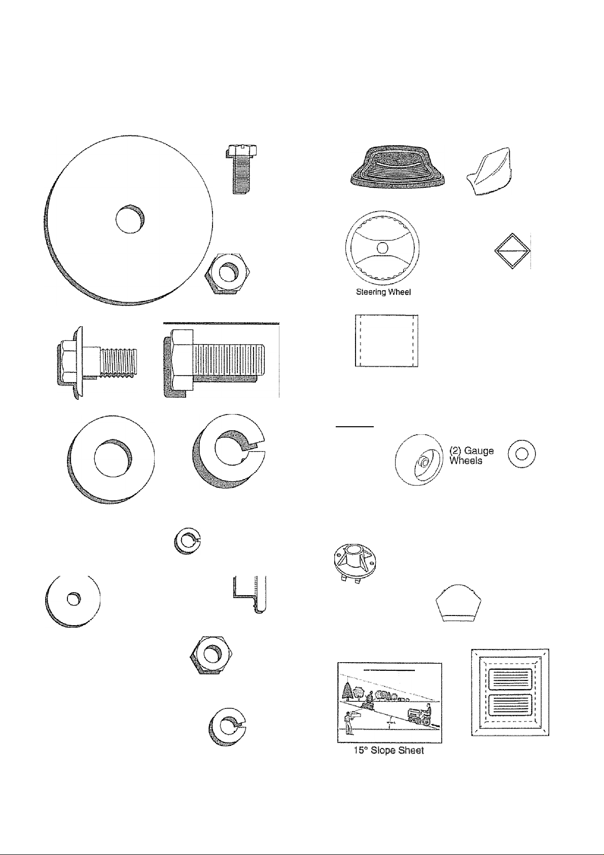
CONTENTS OF HARDWARE PACK
Parts Bag contents shown full size
(2) Sheet
Meta!
Screws
#10-16 X 1/2
{1} Locknut 3/8-24
(1) Large Flat Washer
(1) Shoulder Soft 5/16-18 (1) Hex Boit 1/2-13 x 1
Parts packed separately in carton
Seat
Parts Bag
■r'
, ;• i
I
Steering
Boot
Mulcher
Plata
Sattery acscl
Owner’s Manya!
Parts bag contents not shown full size
(1) Lock Washer 1/2
(1) Washer 17/32 x 1-3/16 x 12 Gauge
(2) Screws #10x5/8 (2) Lock Washers #10
(2) We id Nuts #10
(2) Washers 3/16x3/4x16 Gauge
pu»
(2) Hex Boits 1/4-20 x 3/4
(2) Hex Nuts 1/4-20
|{2) Washers 9/32 x 5/8x16 Gauge
(2) Lock Washers 1/4
(2) Shoulder
Boits
(2) Latch Hook
Assemblys
Steering
Bushing
T3
Steering
Wheel
Adapter
(2) Washers 3/8
X 7/8 X 14 Gauge
j, (2) Genter-
iock Nuts
(2) Keys
Steering Wheel
Insert
Battery Caps
and Instructions
Page 7
ASSEMBLY
Your new tractor has been assembisd at the factory with exception of those parts left unassembled for shipping purposes.
To ensure sale and proper operation of your tractor, all parts and hardware you assemble must be tightened securely. Use
the correct tools as necessary to insure proper tightness.
TOOLS REQUIRED FOR ASSEMBLY
A socket wrench set wiii make assembly easier. Standard
wrench sizes are listed.
{1) 5/16" wrench
{2) 7/16" wrenches
(1) 1/2" wrench
(1) 3/4" wrench
(1) 3/4" socket with drive ratchet
When right and left hand is mentioned in this manual, it
means when you are in the operating position (seated
behind the steering wheel).
TO REMOVE TRACTOR FROM CARTON
UNPACK CARTON
“ Remove ail accessible loose parts and parts cartons
from carton (See page 6).
■> Cut, from top to bottom, along lines on all four corners
of carton, and lay panels flat.
“ Check for any additional loose parts or cartons and
remove,
(1) 9/16* wrench
(1) Phillips screwdriver
Utility knife
Tire pressure gauge
BEFORE ROLLING TRACTOR OFF SKID
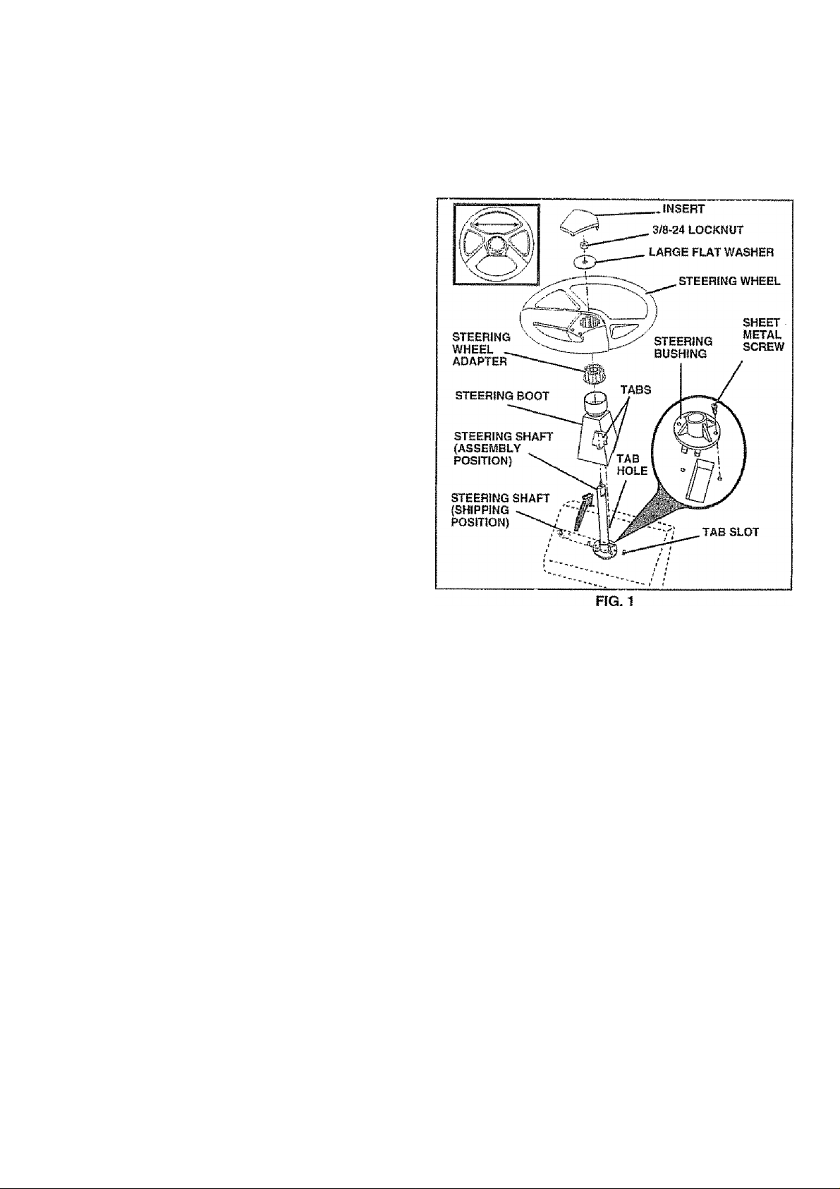
ATTACH STEERING WHEEL (See Fig. 1)
Slide the steering bushing over the steering shaft.
Raise steering shaft forward until screw holes in dash
line up with steering bushing* instali two (2) sheet
metal screws and tighten securely*
Position steering boot over steering shaft.
Place tabs of steering boot over tab slots in dash and
push down to secure.
Slide steering wheel adapteronto upper steering shaft.
Position front wheels of the tractor so they are pointing
straight forward*
Position steering wheel so cross bars are horizontal
(left to right) and slide onto adapter.
Assemble large flat washer and 3/8-24 locknut and
tighten securely..
Snap steering wheel insert into center of steering
wheel.
Remove protective plastic from tractor hood and grill.
iMPORTANT:GHECK FOR AND REMOVE ANY STAPLES
IN SKID THAT MAY PUNCTURE TIRES WHERE TRACTOR
IS TO ROLL OFF SKID.
TO ROLL TRACTOR OFF SKID (See Fig. 7)
" Raise attachment lift lever to its highest position.
“ Release parking brake by depressing clutch/brake
pedal.,
® Place gearshift ¡ever in neutra! (N) position*
" Roil tractor backwards off skid.
" Remove banding holding discharge guard up against
tractor.
Page 8
ASSEMBLY
HOW TO SET UP YOUR TRACTOR
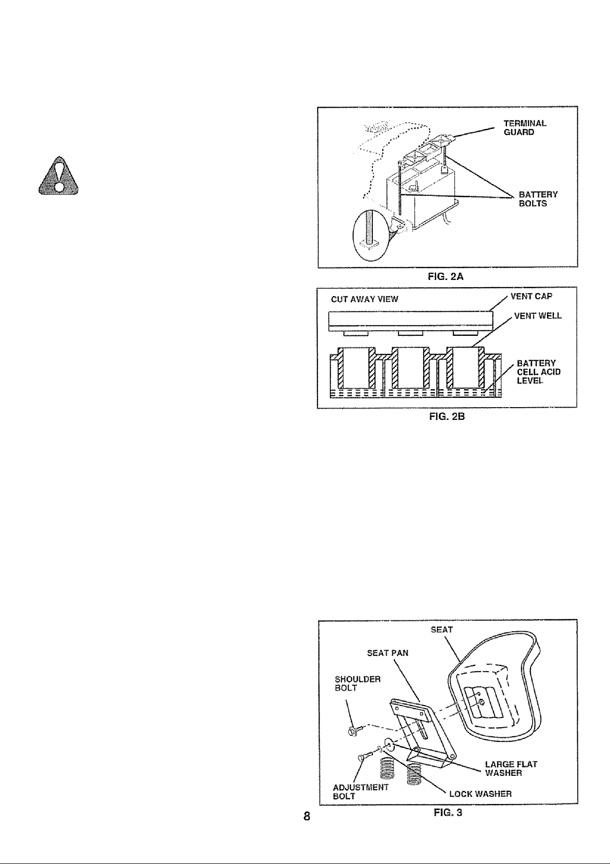
PREPARE BATTERY (See Figs. 2A arid 2B)
CAUTION: Wear eye and face shield.
Wash hands or clothing immediately if
accidentally in contact with battery acid.
Do not smoke. Fumes from charged
battery acid are explosive.
Read the instructions included with the
battery vent caps. Always wear gloves,
clothing and goggles to protect your
hands, skin and eyes.
Your tractor has a battery charging system which is suffi
cient for normal use. However, periodic charging of the
battery with an automotive charger wiil extend Its life
•* See instructions packed with vent caps in parts bag.
» Lift hood to raised position.
« Remove battery from tractor to fill with acid and charge,.
To remove battery, remove terminal guard and battery
bolts securing battery to tractor,
' Fit! battery with acid. Fii! each cell until it reaches the
bottom of the vent wells. Do not overfill.
» Allow battery to stand and settle for at least thirty
minutes. After standing, check the battery cel! acid
level, if beiow the vent wells, add more acid until the
correct level is reached,,
While battery is standing (afteradding acid) and later, while
battery is being charged, continue with assembly of tractor.
IMPORTANT: TO MAXIMIZE THE LIFE OF YOUR
BATTERY, IT IS NECESSARY THAT THE BATTERY BE
CHARGED BEFORE USE. FAILURE TO CHARGE
BATTERY CAN RESULT IN A SHORTENED BATTERY
LIFE.
» Charge battery at a rate of 6 amperes for 1 hour. Use
a 12 volt battery charger. Observe all safety precau
tions required for battery charging.
■> Check the acid level after the battery is charged. If the
acid has fallen below the correct level, add distilled or
iron free water
« install the vent caps to cover the vent wells. Wash the
top of the battery with water to remove any acid, then
wipe dry. .
" Check battery case for leakage to make sure that no
damage has occurred in handiing.
» Dispose of excess battery acid. Neutralize acid for
disposal by adding it to two gallons of water in a five
gaiion plastic container. Stir with a wooden or plastic
paddle while adding baking soda until the addition of
more soda causes no more foaming.
» Follow instructions on how to install battery.
INSTALL SEAT (See Fig. 3)
Adjust seat before tightening adjustment bolt.
■> Remove cardboard packing on seat pan.
“ Place seat on seat pan and assemble shoulder bolt.
“ Assemble adjustment bolt, lockwasherandtiatwasher
loosely , Do not tighten.
= Tighten shoulder bolt securely.
= Lower seat into operating position and sit on seat.
- Slide seat until a comfortable position is reached which
allows you to press clutch/brake pedal all the way
down.
” Get off seat without moving its adjusted position,
“ Raise seat and tighten adjustment bolt securely.
Page 9
ASSEMBLY
CHECK TIRE PRESSURE
The tires on your tractor were overinflated at the factory for
shipping purposes. Correct tire pressure Is important for
best cutting performance.
Reduce tire pressure to PS! shown in “PRODUCT
SPECIFiCATIONS” on page 3 of this manual
CHECK DECK LEVELHESS
For best cutting results, mower housing should be properly
leveled. See ‘TO LEVEL MOWER HOUSING" in the
Service and Adjustments section of this manual,-
CHECK FOR PROPER POSITIOIM OF ALL BELTS
See the figures that are shown for replacing motion and
mower blade drive belts in the Service and Adjustments
section of this manual. Verify that the belts are routed
correctiy
CHECK BRAKE SYSTEM
After you ¡earn how to operate your tractor, check to see
that the brake is properly adjusted. See ‘TO ADJUST
BRAKE" in the Service and Adjustments section of this
manual.
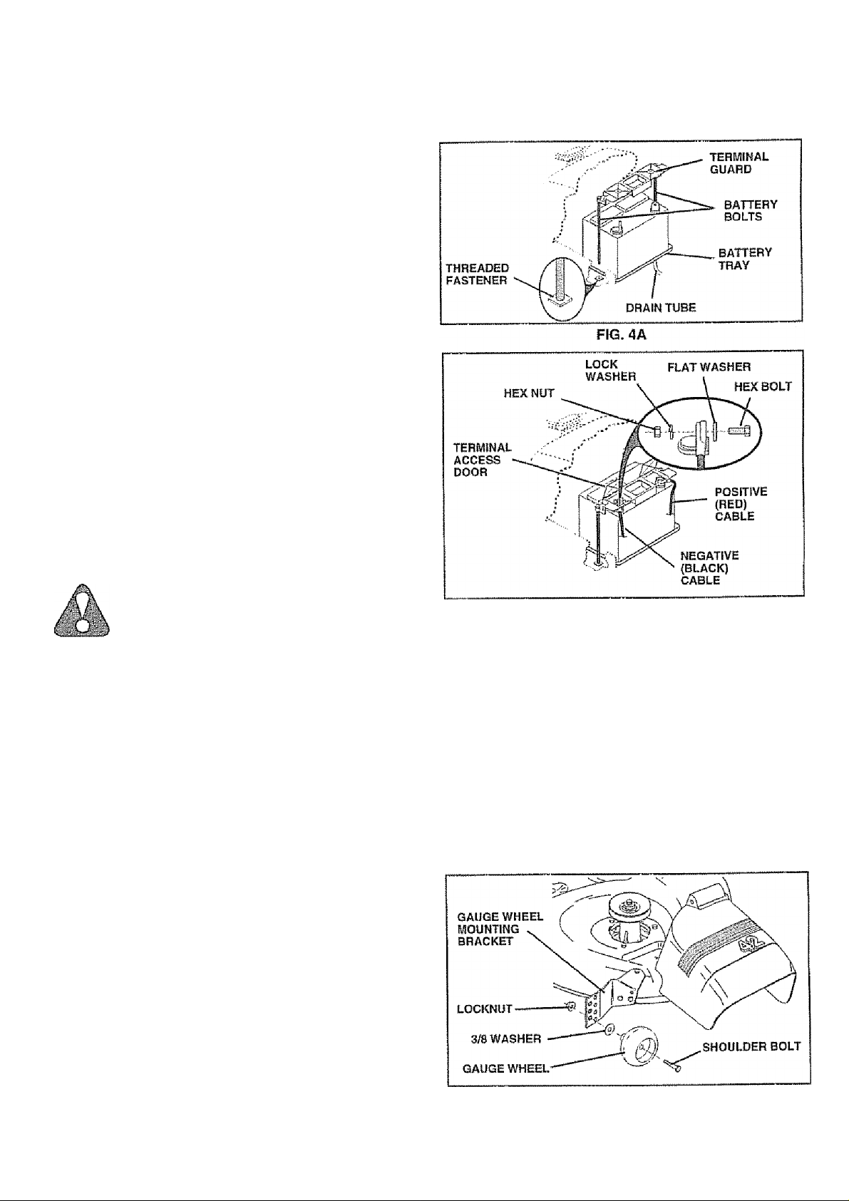
INSTALL BATTERY (See Figs. 4A and 4B)
CAUTION: Do not short battery termi
nals. Before instalfinp battery, remove
metal bracelets, wristwatch bands,
rings, etc.
Positive terminal must be connected
first to prevent sparking from acciden
tal grounding."
w w
“ Lift hood to raised position.
® Be sure battery drain tube has not come loose and Is
securely attached to drain in ijattery tray.
« Lower battery into battery tray with terminals to front of
tractor,
* Position terminal guard over battery and install battery
bolts through guard mounting hoies and into threaded
» Tighten battery boits securely, but do not overtighten.
® Open terminal access doors,
* First connect RED battery cable to positive (+) battery
terminal with hex boit, flat washer, lock washer and hex
nut as shown. Tighten securely,
® Connect BLACK grounding cable to negative (-) battery
terminal with remaining hex baft, flat washer, lock
washer and hex nut. Tighten securely.
® C lose termin a I access doo rs.
Use terminal access doors for:
« Inspection for secure connections (to tighten hard
ware).
® I nspectio n fo r corrosion.
» Testing battery.
* Jumping (if required),
® Periodic charging.
nn <5!linnnri nistP
* *
FIG. 4B
ASSEMBLE GAUGE WHEELS TO MOWER
DECK (See Fig. 5)
Assemble gauge wheels with tractor on a fiat level surface.
® Adjust mower to desired cutting height (See ‘TO AD
JUST MOWER CUTTiNQ HEIGHT’ in the Operation
section of this manuaJ),
0 With mower in desired height of cut position, gauge
wheels should be assembled so they are slightly off the
ground. Install gauge wheel in appropriate hole with
shoulder bolt, 3/8 washer and 3/8-16 locknut and
tighten securely.
* Repeat for opposite side installing gauge wheel in
same adjustment hole.
FIG.5
Page 10
ASSEMBLY
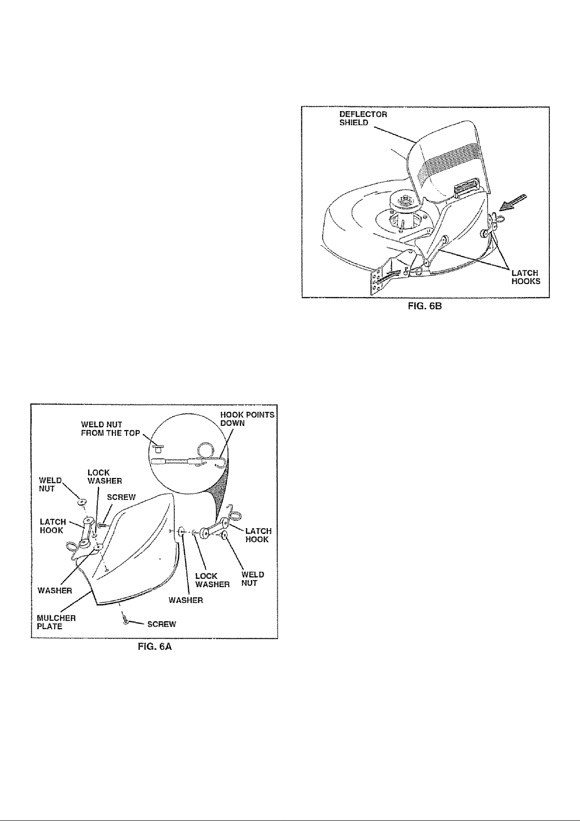
INSTALL MULCHER PLATE
(See Figs. 6A St 6B)
* Install two latch hooks to mulcher plate using screw,
washer, lock washer, and weld nut as shown.
NOTE: Pre-assemble weld nut to latch hook by inserting
weld nut from the top with hook pointing down.
® Tighten hardware securely.
“ Raise and hold deflector shield in upright position.
a Place front of mulcher plate over front of mower deck
opening and slide into place, as shown,,
‘ Hook front latch into hole on front of mower deck,
■> Hook rear latch into hole on back of mower deck.
CAUTION; Do not remove discharge
n. guard from mower. Raise and hold
C- ) and allow it to rest on plate while in
guard when attaching mulcher plate
....
operation.
TO CONVERT TO BAOGING OR
DISCHARGING
Simply remove mulcher plate and store in a safe place.
Your mower is now ready for discharging or installation of
optional grass catcher accessory.
/CHECKLIST
BEFORE YOU OPERATE AND ENJOY YOUR NEW
TRACTOR, WE WISH TO ASSURE THAT YOU RECEIVE
THE BEST PERFORMANCE AND SATISFACTION FROM
THIS QUALITY PRODUCT,
PLEASE REVIEW THE FOLLOWING CHECKLIST:
/ AI! assembly instructions have been completed.
/ No remaining loose parts in carton.
/ Battery is properly prepared and charged. (Minimum
1 hour at 6 amps),
/ Seat is adjusted comfortably and tightened securely,
/ All tires are properly inflated. (For shipping purposes,
the tires were overinflated at the facloiV).
/ Be sure mower deck is properly leveled side-to-s1de/
front-to-rear for best cutting results. (Tires must be
properly inflated for leveling),
/ Check mower and drive belts. Be sure they are routed
properly around pulleys and inside all belt keepers.
/ Check wiring. See that all connections are still secure
and wires are properly clamped.
WHILELEARNING HOWTO USE YOUR TRACTOR, PAY
EXTRA ATTENTION TO THE FOLLOWING IMPORTANT
ITEMS:
V Engine oil is at proper level.
V Fuel tank is tilled with fresh, clean, regular unleaded
gasoline.
/ Become familiar with all controls - their location and
function. Operate them before you start the engine.
/ Be sure brake system is in safe operating condition.
10
Page 11
OPERATION
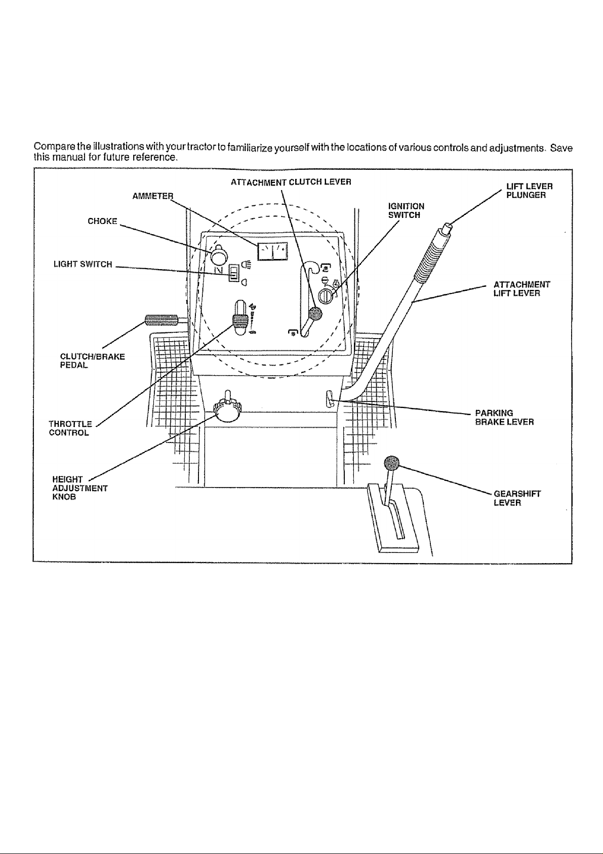
KNOW YOUR TRACTOR
READ THIS OWNER'S iyiANUAL AND SAFETY RULES BEFORE OPERATING YOUR TRACTOR
Our tractors conform to the safety standards of the American National Standards institute.
THROTTLE CONTROL: Used for starting and controlling
engine speed.
CHOKE CONTROL: Used for starting a cold engine.
CLUTCH/BRAKE PEDAL: Used for clutching and braking
the tractor and starting the engine.
HEIGHT ADJUSTMENT KNOB; Used to adjust the mower
cutting height
IGNITION SWITCH: Used for starting and stopping the
engine,
LIGHT SWITCH: Turns the headlights on and off.
AMMETER: ind icates charging (+) or discharging (-) of
battery.
FIG. 7
ATTACHMENT CLUTCH LEVER: Used to engage the
mower biades, or other attachments mounted to your
tractor.
LIFT LEVER PLUNGER: Used to release attachment lift
lever when changing its position.
ATTACHMENT LIFT LEVER: Used to raise and lowerthe
mower deck or other attachments mounted to your tractor.
PARKING BRAKE LEVER: LocksCiutch/Brake Pedallnto
the brake position.
GEARSHIFT LEVER: Selects the speed and direction of
tractor.
11
Page 12
OPERÄTIOM
The operation of any tractor can result in foreign objects thrown into the eyes, which
can result in severe eye damage. Always wear safety glasses or eye shields while
operating your tractor or performing any adjustments or repairs. We recommend a
wide vision safety mask over the spectacles or standard safety glasses.
HOW TO USE YOUR TRACTOR
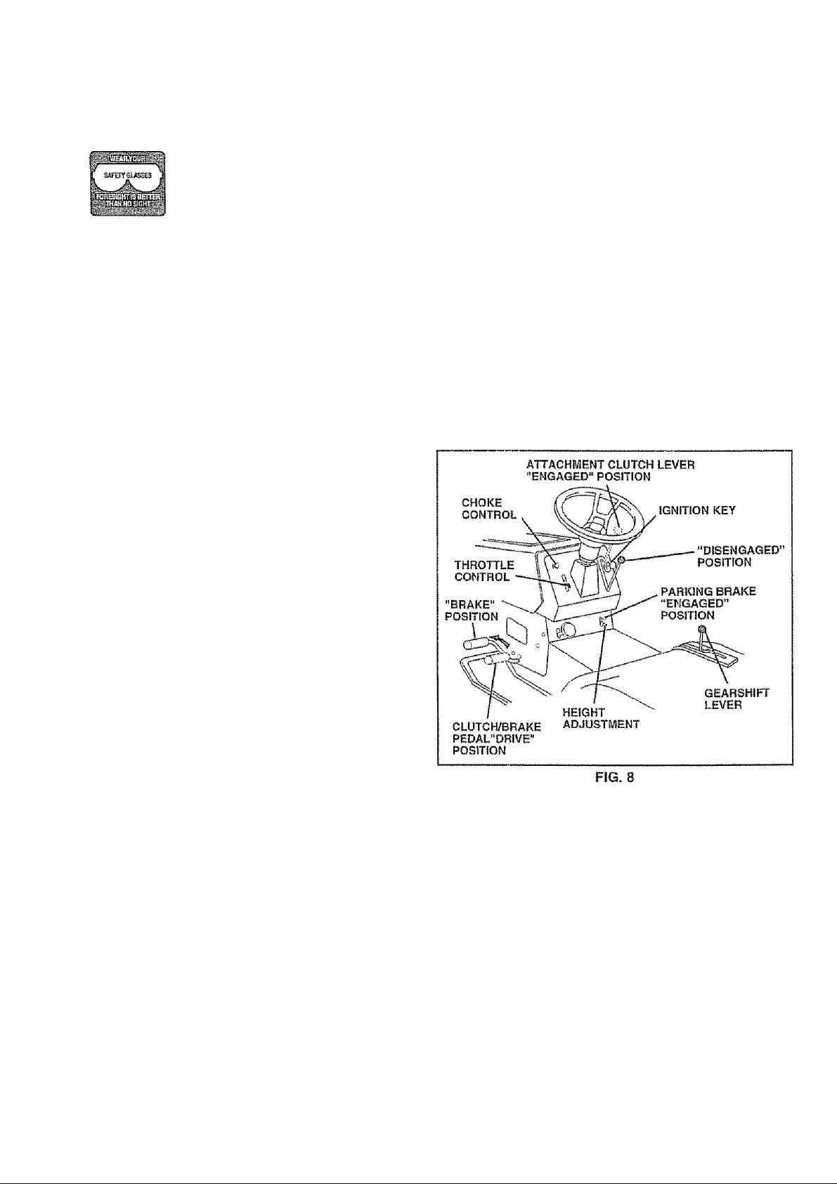
TO SET PARKING BRAKE {See Fig. 8)
Youriractor is equipped with an operator presence sensing
switch. When engine is running, any attempt by the
operator to leave the seat without first setting the parking
brake will shut off the engine.
« Depress clutch/brake pedal into fuil “BRAKE" position
and hold.
0 Place parking brake lever in “ENGAGED" position and
release pressure from clutch/brake pedal. Pedal should
remain in “BRAKE” position. Make sure parking brake
will hold tractor secure.
STOPPING (See Fig. 8)
MOWER BLADES -
o Move attachment clutch lever to “DISENGAGED" po
sition
GROUND DRIVE “ Depress clutch/brake pedal into full "BRAKE" position,
“ Move gearshift lever to neutral (N) position.
ENGINE"
» Move throttle control to slow {-m) position.
NOTE: Failure to move throttle control to slow {•«•)
position and allowing engine to idle before stopping may
cause engine to “backfire",
0 Turn ignition key to "OFF” position and remove key.
Always remove key when leaving tractor to prevent
unauthorized use.
“ Never use choke to stop engine.
NOTE: Under certain conditions when tractor is standing
idle with the engine running, hot engine exhaust gases may
cause “browning” of grass, To eliminate this possibility,
always stop engine when stopping tractor on grass areas.
6 A
TO USE THROTTLE CONTROL (See Fig. 8)
Always operate engine at full throttle,
" Operating engine at less than full throttle reduces the
battery charging rate.
« Fuli throttle offers the best bagging and mower perfor
mance.
TO USE CHOKE CONTROL (See Fig. 8)
Use choke control whenever you are starting a cold engine .
Do not use to start a warm engine,
® To engage choke control, puli knob out. Slowly push
knob in to disengage.
CAUTION: Always stop tractor com
pletely, as described above, before leav
ing the operator’s position; to empty
grass catcher, etc.
TO MOVE FORWARD AND BACKWARD
(See Fig. 8)
The direction and speed of movement Is controlled by the
gearshift lever.
” Start tractor with clutch/brake pedal depressed and
gearshift lever in neutral (N) positlon.
0 Move gearshift lever to desired position.
“ Slowiy release ciutch/brake pedal to start movement
IMPORTANT: BRING TRACTOR TO A COMPLETE STOP
BEFORE SHIFTING OR CHANGING GEARS. FAILURE
TO DO SO WILL SHORTEN THE USEFUL LIFE OF YOUR
TRANSAXLE.
TO ADJUST MOWER CUTTIIMG HEIGHT
(See Fig. 8)
The cutting height is controlled by turning the height adjust
ment knob in desired direction.
« Turn knob clockwise to raise cutting height
” Turn knob counterciockwise to lower cutting
height
The cutting height range is approximately 1 -1/2” to 4”. The
heights are measured from the ground to the blade tip with
the engine not running. These heights are approximate
and may vary depending upon soil conditions, height of
grass and types of grass being mowed..
» The average lawn should be cut to approximately 2-1/2
inches during the cool season and to over 3 inches
during hot months. For healthier and better looking
lawns, mow often and after moderate growth.
® For best cutting performance, grass over 6 inches in
height should be mowed twice. Make the first cut
relatively high; the second to desired height
12
Page 13
OPERATION
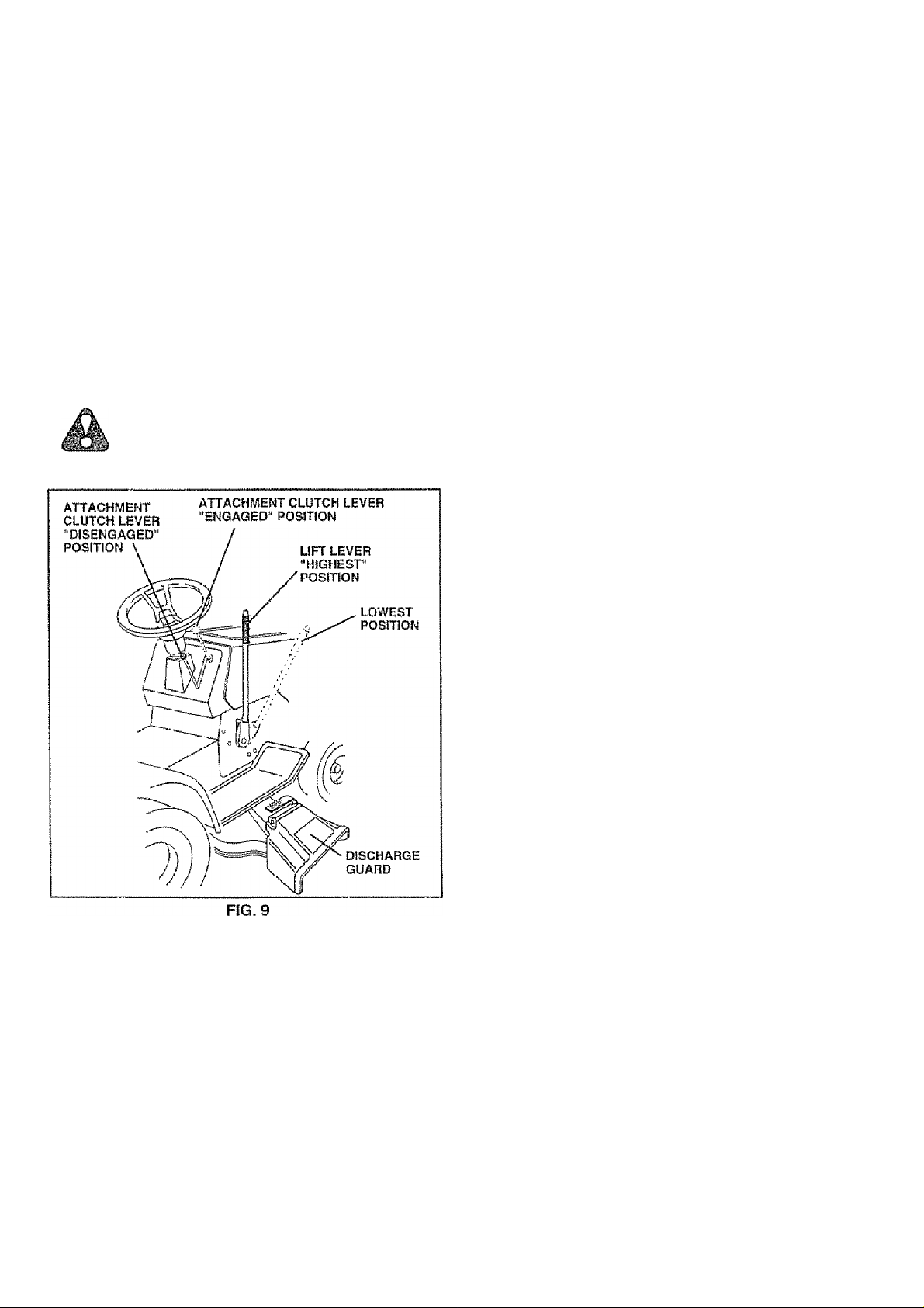
TO OPERATE MOWER (See Fig. 9)
Your tractor is equipped with an operator presence sensing
switch. Any attempt by the operator to leave the seat with
the engine running and the attachment dutch engaged will
shut off the engine.
* Select desired height of cut
» Lower mower with attachment ilft control
« Start mower blades by engaging attachment dutch
control.
• TO STOP MOWER BLADES - disengage attachment
dutch control.
CAUTION: Do not operate the mower
without either the entire grass catcher,
on mowers so equipped, or the dis
charge guard in place.
• Move gearshift lever to 1 si gear. Be sure you have
allowed room for tractor to roll slightly as you restart
movement,
» To restart movement, slowly release parking brake and
clutch/brake pedal.
» Make all turns slowly,
TO TRANSPORT
« Raise attachment lift to highest position with attach
ment lift control-
= When pushing or towing your tractor, be sure gearshift
lever is in neutral (N) position.
• Do not push or tow tractor at more than five (5) MPH.
NOTE: To protect hood from damage when transporting
your tractor on a truck or a trailer, be sure hood is dosed
and secured to tractor., Use an appropriate means of tying
hood to tractor (rope, cord, etc.),
BEFORE STARTING THE ENGINE
CHECK ENGINE OIL LEVEL (See Fig. 15)
“ The engine in your tractor has been shipped, from the
factory, already filled with summer weight oil
= Check engine oil with tractor on ¡eve! ground,
" Remove oil fill cap/dipstick and wipe dean, reinsert the
dipstick and screw cap tight, wait for a few seconds,
remove and read oil level. If necessary, add oil until
“FULL" mark on dipstick is reached. Do not overfi!!.
“ For cold weather operation you should change oil for
easier starting (See “OIL VISCOSITY CHART” in the
Customer Responsibilities section of this manual).
” To change engine oil, see the Customer Responsibili
ties section in this manual.
TO OPERATE ON HILLS
CAUTION: Do not drive up or down
hills with slopes greater than 15“ and
do not drive across any slope.
Choose the slowest speed before starting up or down
hills.
Avoid stopping or changing speed on hills.
if slowing Is necessary, move throttle control lever to
slower position.
If stopping Is absolutely necessary, push clutch/brake
pedal quickly to brake position and engage parking
brake.
ADD GASOLINE
« Fill fuel tank. Use fresh, dean, regular unleaded
gasoline. (Use of leaded gasoiinewill Increase carbon
and lead oxide deposits and reduce valve life).
IMPORTANT: WHEN OPERATING IN TEMPERATURES
BELOW В2 Щ 0' ^С ), USE FRESH, CLEAN WINTER GRADE
GASOLINE TO HELP INSURE GOOD COLD WEATHER
STARTING,
WARNING: Experience indicates that alcohol blended
fuels (called gasohoi or using ethanol or methanol) can
attract moisture which leads to separation and formation of
acids during storage. Acidic gas can damage the fuel
system of an engine white in storage. To avoid engine
problems, the fuel system should be emptied before stor
age of 30 days or longer. Drain the gas tank, start the
engine and let it run until the fuel lines and carburetor are
empty. Use fresh fuel next season. See Storage Instruc
tions tor additional information. Never use engine or
carburetor cleaner products in the fuel tank or permanent
damage may occur.
CAUTION: Fill to bottom of gas tank
filler neck. Do not overfill. Wipe off any
A
spilled oil or fuel. Do not store, spill or
use gasoline near an open flame.
13
Page 14
OPERATION
TO START ENGINE (See Fig. 8)
When starting engine for the first time or if engine has run
out of fuel, it will take extra cranking time to move fuel from
the tank to the engine,
* Depress clutch/brake pedal and set parking brake,,
« Place gearshift iever in neutral (N) position,
« Move attachment clutch to "DiSENGAGED” position.
* Puii choke control out to choke (|\[) position for coid
engine start. For warm engine start do not use choke
control.,
* Move throttle control to midway between fast (•%>) and
slow (•m) positions.
« Insert key into ignition and turn key ciockwise to "START’
position and release key as soon as engine starts. Do
not run starter continuously for more than fifteen
seconds per minute. If engine does not start after
several attempts, move throttle contro! to fast
position, wait a few minutes and try again.
* When engine starts, siowly push choke control in.
* Move throttle control to fast (-^) position
■> Allow engine to warm up tor a few minutes before
engaging drive or attachments.
NOTE: if at a high altitude (above 3000 feet) or in cold
temperatures (below 32®F), the carburetor iuei mixture
may need to be adjusted for best engine performance. See
’TO ADJUST CARBURETOR” in the Service and Adjust
ments section of this manual.
MOWING TIPS
» Tire chains cannot be used when the mower housing
is attached to tractor.
“ Mower should be properly leveled for best mowing
performance. See ‘TO LEVEL MOWER HOUSING" in
the Service and Adjustments section of this manual.
" The [eft hand side of mower should be used for trim
ming.
" Drive so that dippings are discharged onto the area
that has been cut. Have the cut area to the right of the
machine. This wili result in a more even distribution of
clippings and more uniform cutting.
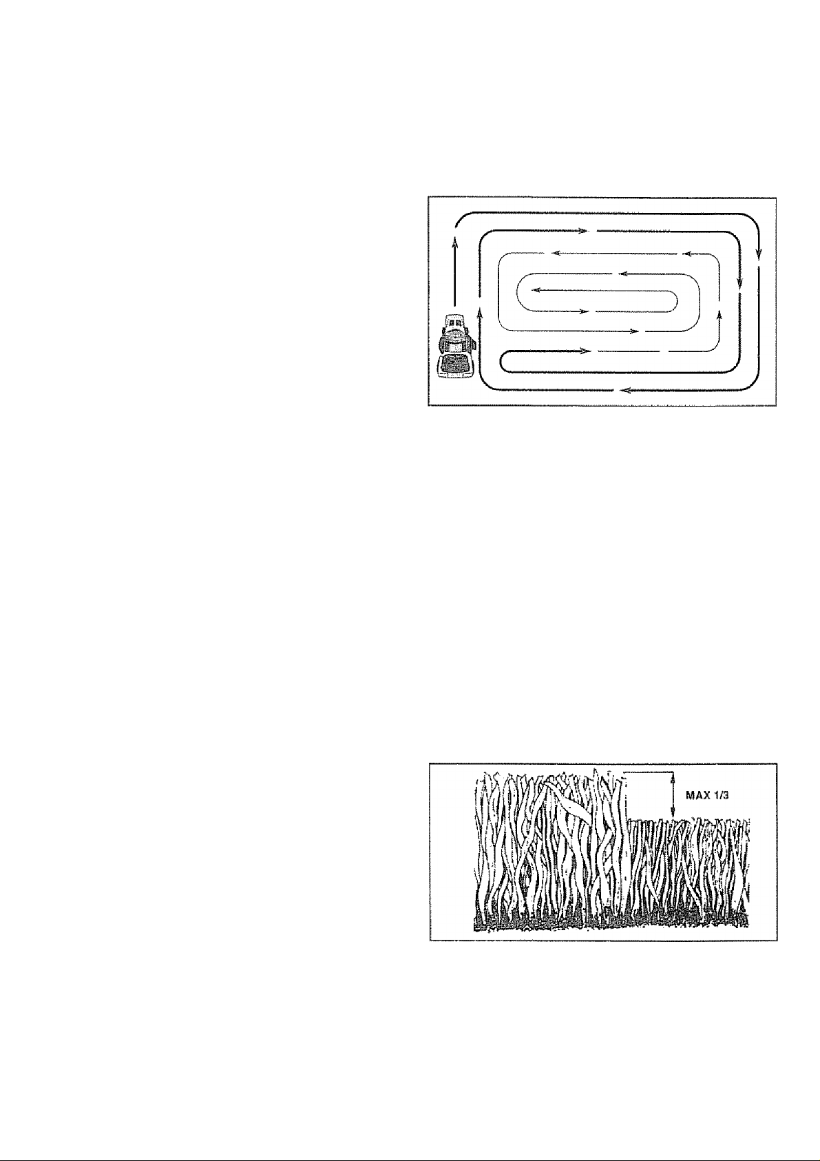
- When mowing large areas, start by turning to the right
so that clippings will discharge away from shrubs,
fences, driveways, etc. After one or two rounds, mow
in the opposite direction making left hand turns until
finished (See Fig 10 ).
<■ If grass is extremely tail, it should be mowed twice to
reduce load and possible fire hazard from dried clip
pings. Make first cut reiatively high; the second to the
desired height.
" Do not mow grass when it Is wet. Wet grass wilt plug
mower and leave undesirable dumps. Allow grass to
dry before mowing.
“ Always operate engine at full throttle when mowing to
assure better mowing performance and proper dis
charge of materia!. Regulate ground speed by select
ing a low enough gear to give the mower cutting
performance as well as the quality of cut desired.
When operating attachments, select a ground speed
that will suit the terrain and give best performance of
the attachment being used
FIG. 10
MULCHING MOWING TIPS
IMPORTANT: FOB BEST PERFORMANCE, KEEP
MOWER HOUSING FREE OF BUILT-UP GRASS AND
TRASH CLEAN AFTER EACH USE.
» The special mulching blade will recut the grass clip
pings many times and reduce them in size so that as
they fall onto the lawn they will disperse into the grass
and not be noticed,. Also, the mulched grass will
biodegrade quickly to provide nutrients for the lawn.
Always mulch with your highest engine (blade) speed
as this wili provide the best recutting action of the
blades
' Avoid cutting your lawn when it is wet. Wet grass tends
to form clumps and interferes with the mulching action.
The best time to mow your lawn is the early afternoon.
At this time the grass has dried and the newiy cut area
will not be exposed to the direct sun.
* For best results, adjust the mower cutting height so that
the mower cuts off oniy the top one-third of the grass
blades (See Fig, 11). For extremely heavy mulching,
reduce your width of cut on each pass and mow slowly.
FIG-11
Certain types of grass and grass conditions may re
quire that an area be mulched a second time to
completely hide the clippings, When doing a second
cut, mow across or perpendicular to the first cut path.
Change your cutting pattern from week to week. Mow
north to south one week then change to east to west the
next week. This will help prevent matting and graining
14
of the iawn.
Page 15
CUSTOMER RESPONSIBILITIES
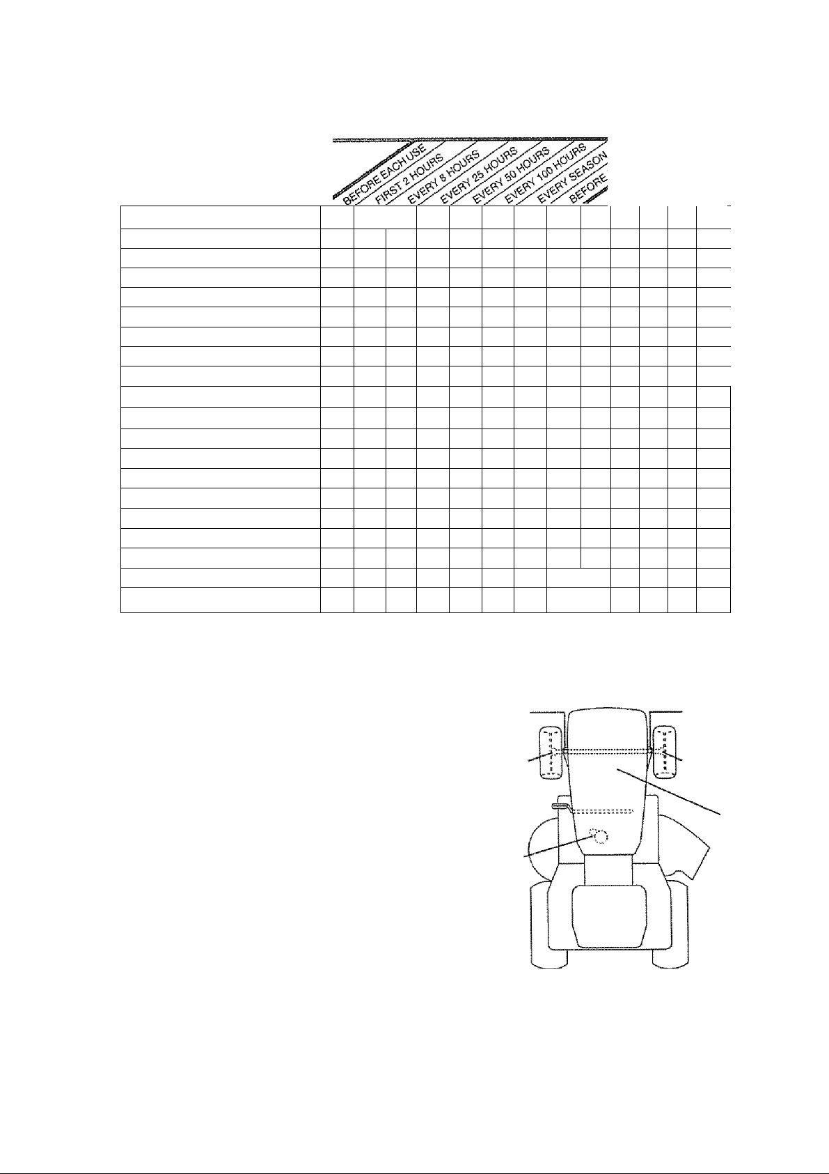
MAINTENANCE SCHEDULE
FfLL !N DATES
AS YOU COMPLETE
REGULAR SERVICE
Check Brake Operation
Check Tire Pressure
Check for Loose Fasteners
Sharpen/Replace Mower Blades
Lubrication Chart
Check Battery Level/Recharge
Clean Battery and Terminals
Check Transaxle Cooling
Adjust Blade Beitfs] Tension
Adjust Motion Drive Belt(s) Tension
Check Engine Oil Level
Change Engine Oil
Clean Air Filler
Clean Air Screen
inspect MuflleriSpark Arrester
Replace Oil Filter (If equipped)
Clean Engine Cooling Fins ^ 2
Replace Spark Plug
Replace Air Filter Paper Cartridge
Replace Fuel Filter
1 - Change more olten whtn aperaling under a heavy !oad or in high ambient temperatures
2 - Service more often when operating in dirty or dusty oottcJitions
3 - If Equipped with oil tittBr, chattga bit every SO hours
4 - Replace blades more oltsn vehsrt mowing In sandy sail
1/
1/
✓
✓
1/
✓
6/
.......
^^3.3
✓ a
✓
.
SERVICE DATES
✓ t
6/
✓
^ s
✓
J
^3
1/
✓
✓
S ■ tl equipped with adjuslabie system5 ■ Not required if equipped with maintenance-lrea battery
7 - Tighten front atria pivot boil to 35 It -tbs. mattimum
Do not overtighten
......
GENERAL RECOSyiMENDATlONS
The warranty on this tractor does not cover items that have
been subjected to operator abuse or negligence. To
receive full vaiue from the warranty, operator must maintain
tractor as instructed in this manual..
Some adjustments will need to be made periodicaily to
properly maintain your tractor
All adjustments in the Service and Adjustments section of
this manual should be checked at ieast once each season.
" Once a year you should replace the spark plug, dean
or replace air filter, and check blades and belts for
wear. A new spark plug and clean air filter assure
proper air-tuet mixture and heip your engine run better
and last longer.
BEFORE EACH USE
» Check engine oil level
- Check brake operation
" Check tire pressure.
■> Check for ioose fasteners.
LUBRICATION CHART
(D SPINDLE ZERK
(g) FRONT WHEEL
BEARING ZERK
® ATTACHMENT
CLUTCH
PiVOTfS)
{]) SAE 30 OR 10W30 MOTOR OIL
<D GENERAL PURPOSE GREASE
(D REFER TO CUSTOMER RESPONSIBILITIES “ENGINE” SECTION
IMPORTANT: DO NOT OIL OR GREASE THE PIVOT POINTS
WHICH HAVE SPECIAL NYLON BEARINGS, VISCOUS LUBRI
CANTS WILL ATTRACT DUST AND DIRT THAT WILL SHORTEN
THE LIFE OF THE SELF-LUBRICATING BEARINGS. IF YOU
FEEL THEY MUST BE LUBRICATED, USE ONLY A DRY, POW
DERED GRAPHITE TYPE LUBRICANT SPARINGLY.
15
SPINDLE ZERK(D
FRONT WHEEL (D
BEARING ZERK
ENGINE (D
Page 16
CUSTOMER RESPONSIBILITIES
TRACTOR
Always observe safety rules when performing any mainte
nance,
BRAKE OPERATION
if tractor requires more than six (6) feet stopping distance
at high speed in highest gear, then brake must be adjusted,
(See TO ADJUST BRAKE” in the Service and Adjust
ments section of this manual)
TIRES
" Maintain proper air pressure in all tires (See “PROD
UCT SPECIFICATIONS" ОП page 3 of this manual).
* Keep tires free of gasoline, oil, or insect control chemi
cals which can harm rubber.
* Avoid stumps, stones, deep ruts, sharp objects and
other hazards that may cause tire damage.
BLADE CARE
For best results mower blades must be kept sharp. Re
place bent or damaged blades.
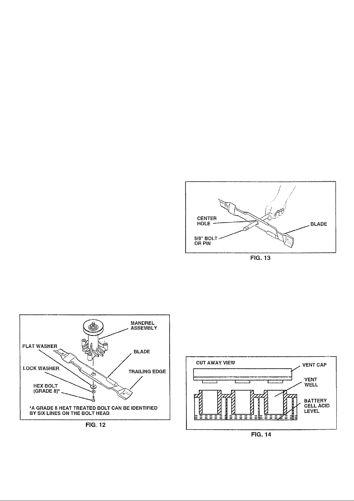
BLADE REMOVAL (See Fig. 12)
" Raise mower to highest position to allow access to
blades
* Remove hexboit, iockwasherandflatwashersecuring
blade.
* Install newi or resharpened blade with trailing edge up
towards deck as shown,
® Reassemble hex bolt, lock washer and Hat washer in
exact order as shown
® Tighten bolt securely (30-35 Ft, Lbs. torque),
IMPORTANT: BLADE BOLT IS GRADE 8 HEAT TREATED
NOTE: We do not recommend sharpening blade - but if you
do, be sure the blade is balanced-
TO SHARPEN BLADE (See Fig. 13)
Care should be taken to keep the blade balanced. An
unbalanced blade will cause excessive vibration and even
tual damage to mower and engine,
■> The blade can be sharpened with a file or on a grinding
wheel Do not attempt to sharpen while on the mower.
» To check blade balance, you will need a 5/8” diameter
steel bolt, pin, or a cone balancer (When using a cone
balancer, follow the instructions supplied with bal
ancer),.
" Slide blade on to an unthreaded portion of the steel bolt
or pin and hold the bolt or pin parallel with the ground.
If blade is balanced, it should remain in a horizontal
position. If either end of the blade moves downward,
sharpen the heavy end until the blade is balanced.
NOTE; Do not use a nail for balancing blade. The lobes of
the center hole may appear to be centered, but are not.
BATTERY (See Fig. 14)
Your tractor has a battery charging system which is suffi
cient for normal use. However, periodic charging of the
battery with an automotive charger will extend its life,
® Acid solution level in each battery cell should be even
with bottoms of vent wells. Add only distilled or iron free
water if necessary. Do not overfill.
“ Keep battery and terminals clean,
“ Keep battery bolts tight
” Keep vent caps tight and small vent holes in caps open,.
" Recharge at 6 amperes for 1 hour.
16
Page 17
CUSTOMER RESPONSIBILITIES
TO CLEAN BATTERY AND TERMINALS
Corrosion and dirt on the battery and terminals can cause
the battery to 'leak'’ power.
' Remove terminal guard,
0 Disconnect BLACK battery cable first then RED
battery cable and remove battery from tractor.
« Wash battery with solution of lour tablespoons of
baking soda to one gallon of water. Be careful not to
get the soda solution into the cells.
« Rinse the battery with plain water and dry.
0 Clean terminals and battery cable ends with wire
brush until bright
“ Coat terminals with grease or petroleum jelly
" Reinstall battery (See “INSTALL BATTERY" in the
Assembly section of this manuaf).
V-BELTS
Check V-beits for deterioration and wear after 100 hours of
operation and repiace if necessary. The belts are not
adjustable. Replace belts If they begin to slip from wear.
TRANSAXLE COOLING
Keep transaxle free from build-up of dirt and chaff which
can restrict cooling.
ENGINE
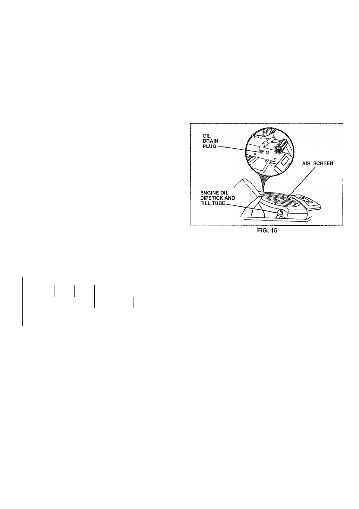
Afteroil has drained completely, replace oil drain plug
and tighten securely.
Refill engine with oil through oil fill dipstick tube. Pour
slowly. Do not overfill. For approximate capacity see
“PRODUCT SPECIFICATIONS” on page 3 of this
manual.
Use gauge on oil fill dipstick for checking level. Be sure
dipstick cap is tightened securely for accurate reading.
Keep oil at “FULL" line on dipstick.
LUBRICATION
Only use high quality detergent oil rated with API service
classification SF or SG. Select the oil’s SAE viscosity
grade according to your expected operating temperature.
SAE VISCOSITY GRADES
-7уГТ~
“20®
“F
"C .30"
ТЕМРЁНАТиНЕ RAWee ANTICIPATED BEFORE NEXT OIL CHANGE
NOTE: Although multi-viscosity oils (5W30, 10W30 etc.)
0" ЗО*" 32’ 40^
20" -tO" 0" 10* 20“ 30“ 40“
improve starting in cold weather, these multi-viscosity oils
will result In increased oil consumption when used above
32°F. Check your engine oil level more frequently to avoid
possible engine damage from running low on oil.
Change the oil after the first two hours of operation and
every 25 hours thereafter or at least once a year if the
tractor is not used for 25 hours in one year.
Check the crankcase oil level before starting the engine
and after each eight (8) hours of operation. Tighten oil fill
cap/dipstick securely each time you check the oil level.
TO CHANGE ENGINE OIL (See Fig.15)
Determine temperature range expected before oil change.
All oil must meet API service classification SF or SG.
* Be sure tractor Is on level surface.
” Oil will drain more freely when warm.
” Catch oil in a suitable container,
® Remove oil fill dipstick. Be careful not to allow dirt to
enter the engine when changing oil.
® Remove drain plug.
Л.
60' 80“ 1Й0"
-C?
CLEAN AIR SCREEN (See Fig. 15)
Air screen must be kept free of dirt and chaff to prevent
engine damage from overheating. Clean with a wire brush
or compressed air to remove dirt and stubborn dried gum
fibers.
AIR FILTER (See Fig. 16)
Your engine will not run properly using a dirty air filter.
Glean the foam pre-cleaner element after every 25 hours of
operation or every season. Service paper cartridge every
100 hours or every season, whichever occurs first.
Service air cleaner more often under dusty conditions
" Remove knob(s) and cover,
TO SERVICE PRE-CLEANER
" Slide foam pre-cleaner off cartridge,
o Wash it in liquid detergent and water.
® Squeeze it dry in a clean cloth.
• Saturate it in engine oil* Wrap it in clean, absorbent
cloth and squeeze to remove excess oil.
» If very dirty or damaged, repiace pre-cleaner.
' Reinstall pre-cleaner over cartridge.
, Reinstall cover and secure with knob(s).
TO SERVICE CARTRIDGE
• Remove wing nuts and cartridge plate.
« Carefully remove cartridge to prevent debris from
entering carburetor.
' Clean cartridge by tapping gently on flat surface. Ifvery
dirty or damaged, replace cartridge.
» Reinstall cartridge plate, wing nuts, precleaner, cover
and secure with knob(s).
17
Page 18

CUSTOMER RESPONSIBILITIES
IMPORTANT: PETROLEUM SOLVENTS, SUCH AS
KEROSENE, ARE NOT TO BE USED TO CLEAN THE
CARTRIDGE. THEY MAY CAUSE DETERIORATION OF
THE CARTRIDGE. DO NOT OIL CARTRIDGE, DO NOT
USE PRESSURIZED AIR TO CLEAN OR DRY
CARTRIDGE,
MUFFLER
Inspect and replace corroded muffler and spark arrester (if
equipped) as it could create a fire hazard and/or damage.
SPARK PLUGS
Replace spark plugs at the beginning of each mowing
season or after every 100 hours of use, whichever comes
first Spark plug type and gap setting is shown in "PROD
UCT SPECIFICATIONS" on page 3 of this manual
IN-LINE FUEL FILTER (See Fig. 18}
The fuel filter should be replaced once each season If fuel
filter becomes clogged, obstructing fuel flow to carburetor,
replacement is required,
o With engine cool, remove filter and plug fuel line
sections,
« Place new fuel filter in position in fuel line with arrow
pointing towards carburetor,
» Be sure there are no fuel line teaks and clamps are
properly positioned.
• Immediately wipe up any spiiled gasoline.
FIG 16
i I ЧЛг I VA
ENGINE COOLING FINS (See Fig. 17)
Remove any dust, dirt or oil from engine cooling fins to
prevent engine damage from overheating. Air guide covers
must be removed. Remove side panels and hood (See "TO
REMOVE HOOD AND GRILL ASSEMBLY" in the Service
and Adjustments section of this manual)
CLEANING
О Glean engine, battery, seat, finish, etc,, of all foreign
matter
» Keep finished surfaces and wheels free of all gasoline,
oil, etc.
» Protect painted surfaces with automotive type wax.
We do not recommend using a garden hose to clean your
tractor unless the electrical system, muffler, air filter and
carburetor are covered to keep water out, Water In engine
can result in a shortened engine life.
Page 19

SERVICE AND ADJUSTMENTS
CAUTION: BEFORE PERFORMING ANY SERVICE OR ADJUSTMENTS:
« Depress clutch/brake pedal fully and set parking brake.
» Place gearshift lever in neutral (N) position.
® Place attachment clutch in “DISENGAGED” position.
» Turn ignition key “OFF” and remove key.
® Make sure the blades and all moving parts have completely stopped.
» Disconnect spark plug wire from spark plug and place wire where it cannot come in contact with
plug.
TRACTOR
TO REMOVE MOWER (See Fig. 19)
Mower will be easier to remove from the rig ht side of tracto r.
Place attachment clutch in "DISENGAGED” posltion.
Move attachment lift leverforward to lowermowarto its
lowest position,
Roll belt off engine pulley.
Disconnect clutch rod from clutch lever by removing
retainer spring.
Disconnect anti-sway bar from chassis bracket by
removing retainer spring.
Disconnect suspension arms from rear deck brackets
by removing retainer springs.
Disconnect front links from deck by removing retainer
springs.
Raise fift lever to raise suspension arms. Slide mower
out from under tractor.
iMPORTANT: IF AN ATTACHMENT OTHER THAN THE
MOWER IS TO BE MOUNTED TO THE TRACTOR, THE
R.H. AND L,H. SUSPENSION ARMS MUST BE REMOVED
FROM TRACTOR
TO INSTALL MOWER (See Fig. 19)
» Raise attachment lift lever to its highest position.
0 Slide mower undertractor with discharge guard to right
side of tractor.
« Lower lift iever to its lowest position.
0 install mower in reverse order of removal instructions.
FIG, 19
19
Page 20

SERVICE AND ADJUSTMENTS
TO LEVEL MOWER HOUSINO
Adjust the mower while tractor is parked on level ground or
driveway. Make sure tires are properly Inflated (See
"PRODUCT SPECiFlCATIONS”on page 3 of this manual),
if tires are over or underinflated, you will not properly adjust
your mower,
SIDE-TO-SIDE ADJUSTMENT (See Figs, 20 and 21)
" Raise mower to its highest position,
" At the midpoint of both sides of mower, measure height
from bottom edge of mowerto ground., Distance “A" on
both sides of mower should be the same or within 1/4“
of each other.
' If adjustment is necessary, make adjustment on one
side of mower oniy
" To raise one side of mower, tighten lift [ink adjustment
nut on that side.
" To lower one side of mower, ioosen lift ¡ink adjustment
nut on that side,
NOTE: Each full turn of adjustment nut will change mower
height about 1/8",
« Recheck measurements after adjusting.
r HUlNl I - I U~oAUi\ AUJUo i iViciN I (oG6 rlQS. ¿¿id anO do)
IVIPORTANT: DECK MUST BE LEVEL SIDE-'TG''SIDE. IF
THE FOLLOWING FRONT-TO-BACK ADJUSTMENT IS
NECESSARY, BE SURETO ADJUST BOTH FRONT LINKS
EQUALLY SO MOWER WILL STAY LEVEL SIDE-TO-
S, p. ^
lutz.
Tr% QAr’U' AH h ICTJkAITMT /Cnn Cane' OO 00\
To obtain the best cutting results, the mower housing
should be adjusted so that the front is approximately 1/4“ to
3/4" lower than the rear when the mower is in its highest
position.
Check adjustment on right side of tractor. Measure dis
tance "D” directly in front and behind the mandrel at bottom
edge of mower housing as shown.
" Before making any necessary adjustments, check that
both front links are equal in length. Both links should be
approximately 10-3/8“.
" If links are not equal in length, adjust one link to same
length as other iink,
“ To lower front of mower loosen nut “E” on both front
links an equal number of turns,
« When distance “D" is 1/4" to 3/4“ iower at front than
rear, tighten nuts “F” against trunnion on both front
links,
• To raise front of mower, loosen nut “F* from trunnion on
both front links. Tighten nut “E" on both front links an
equal number of turns*
* When distance “D" is 1/4“ to 3/4" lower at front than
rear, tighten nut “F" against trunnion on both front links.
s Recheck side-to-side adjustment
LIFT LINK
ADJUSTMENT NUT
FIG. 21
Page 21

SERVICE AND ADJUSTMENTS
TO REPLACE MOWER BLADE DRIVE BELT
(See Fig. 24)
The mower blade drive belt may be replaced without tools.
Park the tractor on level surface. Engage parking brake,
BELT REMOVAL -
» Remove mower from tractor (See 'TO REMOVE
MO\A/ER" in this section of this manual)
» Work belt off both mandrel pulleys and idler pulleys.
» Pull belt away from mower.
BELT INSTALLATION -
» Install new belt in reverse order of removal.
« Make sure belt is in all pulley grooves and inside all belt
guides.
® install mower in reverse order of removal instructions.
TO REPLACE MOTION DRIVE BELT
(See Fig. 26)
Park the tractor on level surface. Engage parking brake.
For assistance, there is a belt installation guide decal on
bottom side of left footrest,
• Remove mower (See TO REMOVE MOWER" in this
section of this manual.)
" Remove upper beit keeper.
• Remove belt from stationary idler and clutching idler.
« Pull beit slack toward rear of tractor. Remove belt
upwards from transaxle puiley by deflecting belt keep
ers.
« Pull beit toward front of tractor and remove downwards
from around engine puliey,
" Install new beit by reversing above procedure.
iiVlPORTAilT: MAKE SURE UPPER SELT KEEPER IS
POSITIONED PROPERLY BETWEEN LOCATOR TABS.
TO ADJUST BRAKE (See Fig. 25)
Your tractor is equipped with an adjustable brake system
which is mounted on the right side of the transaxle.
If tractor requires more than six (6) feet stopping distance
at high speed in highest gear, then brake must be adjusted.
* Depress ciutch/brake pedal and engage parking brake.
• Measure distance between brake operating arm and
nut “A" on brake rod.
“ If distance is other than 1 -1/2", loosen jam nut and turn
nut “A” until distance becomes 1-1/2". Retighten Jam
nut against nut *'A".
0 Road test tractor for proper stopping distance as stated
above. Readjust if necessary. If stopping distance is
still greater than six (6) feet in highest gear, further
maintenance is necessary. Contact your nearest
authorized service center/department,
FIG. 26
21
Page 22

SERVICE AND ADJUSTMENTS
TO ADJUST STEERING WHEEL ALIGNMENT
If steering whee! crossbars are not horizontal (left to right)
when wheels зге positioned straight forward, remove steer"
Ing wheel and reassemble per instructions in the Assembly
section of this manual.
FRONT WHEEL TOE-IN/CAMBER
The front whee! toe-in and camber are riot adjustable on
youf tractor- If damage has occurred to affect the front
wheel toe-in or camber, contact your nearest authorized
service center.
TO REMOVE WHEEL FOR REPAIRS
(See Fig. 27)
« Block up axle securely.
•• Remove axle cover, retaining ring and washers to allow
wheel removal (rear wheel contains a square key - Do
not lose).
“ Repair tire and reassembie.
“ On rear wheels only: align grooves In rear whee! hub
and axle. Insert square key.
« Replace washers and snap retaining ring securely in
axle groove.
« Replace axle cover.
TO START ENGINE WITH A WEAK BATTERY
(See Fig. 28)
CAUTION: Lead-acid batteries gener-
Ok ate explosive gases. Keepsparks,flame
and smoking materials away from bat
teries. Always wear eye protection
■■ " when around batteries.
If your battery is too weak to start the engine, it should be
recharged. If “Jumper cables" are used for emergency
starting, follow this procedure:
IMPORTANT; YOUR TRACTOR IS EQUIPPED WITH A 12
VOLT NEGATIVE GROUNDED SYSTEM, THE OTHER
VEHICLE MUST ALSO BE A 12 VOLT NEGATIVE
GROUNDED SYSTEM. DO NOT USE YOUR TRACTOR
BATTERY TO START OTHER VEHICLES
TO ATTACH JUMPER CABLES " Connect each end of the RED cable to the POSITIVE
(+} terminal of each battery, taking care not to short
against chassis.
“ Connect On© end of the BLACK cable to the NEGA
TIVE (-) terminal of fully charged battery.
" Connect the other end of the BLACK cable to good
CHASSIS GROUND, away from fuel tank and battery.
TO REMOVE CABLES, REVERSE ORDER » BLACK cable first from chassis and then from the fully
charged battery,
<• RED cable last from both batteries.
22
FIG. 28
Page 23

SERVICE AND ADJUSTMENTS
TO REPLACE HEADLIGHT BULB
= Raise hood.
" Pull bulb holder out of the hole in the backside of the
grill,
» Replace bulb in holder and push bulb holder securely
back Into the hole in the backside of the grill,
* Close hood.
INTERLOCKS AND RELAYS
Loose or damaged wiring may cause your tractor to run
poorly, stop running, or prevent it from starting.
• Check wiring,, See electrical wiring diagram in Repair
Parts section of this manuai.
TO REPLACE FUSE
Replace with 30 amp automotive-type plug-in fuse. The
fuse holder is located behind the dash.
TO REMOVE HOOD AND GRILL (See Fig. 29)
■> Raise hood.
» Unsnap headlight wire connector,
■> Stand in front of tractor. Grasp hood at sides, tilt
forward and lift off of tractor.
“ To reinstall, slide hood pivot brackets into slots in
frame.
" Reconnect headlight wire connector and close hood.
ENGINE
TO ADJUST THROTTLE CONTROL CABLE
(See Fig, 30)
The throttle control has been preset at the factory and
adjustment should not be necessary. Check adjustment as
described below before loosening cable, if adjustment is
necessary, proceed as follows:
® With engine not running, move throttle control lever to
fast (•!») position.
* Check that swivel is against side of quarter circle. If it
is not, loosen cable clamp screw and pull cable back
until swivel is against quarter circle. Tighten cable
damp screw securely.
TO ADJUST CHOKE CONTROL (See Fig. 31)
The choke control has been preset at the factory and
adjustment should not be necessary. Check adjustment as
described below before loosening cable. If adjustment is
necessary, proceed as follows;
» With engine not running, move choke control (located
on dash panel) to full choke (|\|) position.
» Remove air cleaner cover, filter and cartridge plate to
expose carburetor choke (see “AIR FILTER" in the
Customer Responsibilities section of this manual),
« Choke should be dosed, if it is not, loosen casing
clamp screw and move choke cable until choke is
completely closed. Tighten casing damp screw se
curely
a Reassemble air cleaner.
23
Page 24

SERVICE AND ADJUSTMENTS
TO ADJUST CARBURETOR
(See Figs. 32 and 33)
The carburetor has been preset at the factory and adjust
ment should not be necessary. However, minor adjust
ment maybe required iocompensatefordifferences in fuel,
temperature, altitude or load. If the carburetor does need
adjustment, proceed as foHows:
In general, turning the mixture screw in (clockwise) de
creases the supply of fuel to the engine giving a leaner fuel/
air mixture. Turning the mixture screw out (counterclock
wise) increases the supply of fuel to the engine giving a
richer fuel/air mixture.
MViPORTANT: DAMAGE TO THE NEEDLES AND THE
SEATS IN CARBURETOR MAY RESULT IF SCREW IS
TURNED IN TOO TIGHT
PRELIMINARY SETTING “ Be sure you have a clean air filter, and the throttle
control cable and choke are adjusted properly (see
above),
• With engine off turn idle mixture screw in (clockwise)
closing it finger tight and then turn out (counterciockwise) 1 -1/4 to 1-1/2 turns.
FINAL SETTING -
■* Start engine and allow to warm for five minutes. Make
final adjustments with engine running and shift/ motion
control lever in neutral (N) position.
. With throttle control lever in slow (*^) position, hold
throttle lever against idle speed screw and adjust idle
speed screw to obtain 1200 to 1400 RPM,,
“ While stii! holding throttle lever against idle speed
screw, turn idle mixture screw in (clockwise) until
engine begins to die and then turn out (counterclock
wise) until engine runs rough. Turn screw to a point
midway between those two positions.
“ Continue to hold throttle lever against idle speed screw
and adjust idle speed screw to obtain 900 to 1200 RPM.
Release throttle lever.
ACCELERATION TEST * Move throttle control ¡ever from slow (*®) to fast (•%?)
position, if engine hesitates or dies, turn idle mixture
screw out (counterclockwise) 1/8 turn. Repeat test
and continue to adjust, if necessary, until engine accel
erates smoothly.
High speed stop is
damage may result,
IMPORTANT: NEVER TAMPER WITH THE ENGINE
GOVERNOR, WHICH IS FACTORY SET FOR PROPER
ENGINE SPEED, OVERSPEEDING THE ENGINE ABOVE
THE FACTORY HIGH SPEED SETTING CAN BE
DANGEROUS IF YOU THiNKTHE ENGINE-GOVERNED
HIGH SPEED NEEDS ADJUSTING, CONTACT YOUR
NEAREST AUTHORIZED SERVICE CENTER/
DEPARTMENT, WHICH HAS PROPER EQUIPMENT AND
EXPERIENCE TO MAKE ANY NECESSARY
ADJUSTMENTS
factory adjusted. Do not adjust -
24
Page 25

STORAGE
Immediately prepare your tractor for storage at the end of
the season or if the tractor will not be used for 30 days or
more.
CAUTION; Never store the tractor with
gasoline in the tank inside a building
where fumes may reach an open flame
or spark. Allow the engine to cool
before storing in any enclosure.
TRACTOR
Remove mower from tractor for winter storage. When
mower is to be stored tor a period of time, clean it thor
oughly, remove all dirt, grease, leaves, etc. Store in a
clean, dry area.
■> Clean entire tractor (See “CLEANING" in the Customer
Responsibilities section of this manual),
" Inspect and replace belts, if necessary (See belt re
placement Instructions in the Service and Adjustments
section of this manual).
" Lubricate as shown in the Customer Responsibilities
section of this manual.
» Be sure that all nuts, bolts and screws are securely
fastened. Inspect moving parts for damage, breakage
and wear, Replace if necessary.
« Touch up all rusted or chipped paint surfaces; sand
lightly before painting.
BATTERY
« Fully charge the battery lor storage.
® After a period of time in storage, battery may require
recharging.
» To help prevent corrosion and power leakage during
long periods of storage, battery cables should be
disconnected and battery cleaned thoroughly (see'TO
CLEAN BATTERY AND TERMINALS" in the Cus
tomer Responsibilities section of this manual).
® After cleaning, leave cables disconnected and place
cables where they cannot come In contact with battery
terminals,
» Be sure battery drain tube Is securely attached.
» If battery is removed from tractor tor storage, do not
store battery directly on concrete or damp surfaces.
ENGINE
FUEL SYSTEM
lyPOBTANT: IT IS IMPORTANT TO PREVENT GUM
DEPOSITS FROM FORMING IN ESSENTIAL FUEL
SYSTEM PARTS SUCH AS CARBURETOR, FUEL FILTER,
FUEL HOSE, OR TANK DURING STORAGE. ALSO,
EXPERIENCE INDICATES THAT ALCOHOL BLENDED
FUELS (GALLED GASOHOL OR USING ETHANOL OR
METHANOL) CAN ATTRACT MOISTURE WHICH LEADS
TO SEPARATION AND FORMATION OF ACIDS DURING
STORAGE. ACIDIC GAS CAN DAMAGE THE FUEL
SYSTEM OF AN ENGINE WHILE IN STORAGE,
• Drain the fuel tank.
« Start the engine and let it run until the fuel lines and
carburetor are empty,
® Never use engine or carburetor cleaner products in the
fuel tank or permanent damage may occur
» Use fresh fuel next season.
NOTE: Fuel stabilizer is an acceptable alternative In
minimizing the formation of fuel gum deposits during stor
age. Add stabilizer to gasoline in fuel tank or storage
container. Always follow the mix ratio found on stabillpr
container. Run engine at least 10 minutes after adding
stabilizer to allow the stabilizer to reach the carburetor. Do
not drain the gas tank and carburetor if using fuel stabilizer.
ENGINE OIL
Drain oi) (with engine warm) and replace with clean engine
oii. (See "ENGINE” in the Customer Responsibilities
section of this manual),
CYLINDERS
• Remove spark piug(s).
« Pour one ounce of oil through spark plug hole(s) into
cylinder(s).
« Turnignitionkeyto"START’'positionforafewseconds
to distribute oil.
» Replace with new spark p!ug(s)
OTHER
» Do not store gasoline from one season to another.
0 Replace your gasoline can if your can starts to rust.
Rust and/or dirt in your gasoline will cause problems.
• if possible, store your tractor indoors and cover it to
give protection from dust and dirt.
« Cover your tractor with a suitable protective cover that
does not retain moisture. Do not use plastic. Plastic
cannot breathe which allows condensation to form and
will cause your tractor to rust,
IMPORTANT: NEVER GOVERTRACTOR WHILE ENGINE
AND EXHAUST AREAS ARE STILL WARM
25
Page 26

TROUBLESHOOTING POINTS
PROBLEM
Wlii not start
Hard to start
Engine will not turn over
CAUSE
1, Out of fuel,
2 - Engine not "CHOKE D" properly
3, Engine ftooded.
4, Bad sparkplug
Dirty air filter
6- Dirty fuel filter
7. Water In fuel
8 - Loose or damaged wiring
9 Carburetor out of adjustment
10, Engine valves out of adjustment,.
1 Dirty air filter,
2. Bad spark plug.
3. Weak or dead battery
4. Dirty fueHiiter
5. Stale or dirty fuel.
6. Loose or damaged wiring
7- Carburetor out of adjustment
0. Engine valves out of adjustment,
1, ClutcWbrake pedal not depressed.
2 Attachment dutch is e ngaged,
3, Weak or dead battery
4, Blown fuse,
5, Corroded battery terminaisS Loose or damaged wiring
7, Faulty ignition switch
8, Faulty solenoid or starts r,
9 Faulty operator presence swi tch(es|
CORRECTION
1 Fili fuel tank.
2 See 'TO START ENGINE" in Operation section,
3. Walt several minutes before attempting to start,
4 Replace spark plug,
5 Clean/repiace air filter
6 Replace fuei filter
7 Drain fuel tank and carburetor, refill tank with fresh
gasoline and replace fuel filter
8. Check all wiring
9. Contact ari authorized service center/department.
10- Contact an authorized service center/department.
1 Clean/repiace air filter
2 Replace spark plug
3 Recharge or replace battery
4 Replace fuel filter.
5. Drain fuel tank and refill with fresh gasolina..
6 Check all wiring
7 Contact ari authorized service center/department,
8 Contact an aiithorizad service center/department.
1 Depress clutch/brake pedal,
2 Disengage attachment dutch
3 Recharge or replace battery
4 Replace fuss.
5 Clean battary terminals
6. Check all wiring
7 Check/replaca ignition switch
8. Check/replaca soianoid or starter
9, Contact an authorized service center/department-
Engine dicks but will not
start
Loss of power
Excessive vibration
1 - Weak Of dead battery,
2- Corroded battery terminals.
3- Loose or damaged wiring
4. Faulty solenoid or starter.
1. Cutting loo much grass/too fast
2 Throttie in “CHOKE" position
3 Build-up of f rasSi leaves and trash under mower
4 Dirty air filter,
5, Low Oil ievsi/dirty oil.
6, Faulty Spark plug
7 Dirty fuel filter
6 Stale or dirty fuel,
9 Water In fuel
10 Spark plug wire loose
11 Dirty engine air screen/fins,
12. Dirly/dogged muffler,
13- Loose or damaged wiring
14 Carburetor out of adjustment,
15 Engine valves out of adjustment.
1, Worn, bent or loose biada,
2, Bent blade mandrel.
3 Loose/damaged part(s)
1 Recharge or replace battery
2 Clean battery terminals
3 Check alt wiring,
4 Check/replace solenoid or starter
1 Set In "Higher Cut" positlon/reduce spaed
2 Adjust throttle control,
3 Clean underside of mower housing,
4, Ctean/replace air filter,
5 Check oil level/change oil.
6 Clean and regap or change spark plug.
7 Replace fuel fitte r,
8, Drain fuel tank and refill with fresh gasoline
9 Drain fuei tank and carburetor, refill tank with fresh
gasoline and replacB fuel filter,
10, Connect and tighten spark plug wire.
11, Clean engine air screen/flns,
12, CJean/replacB muffler
13, Check all wiring.
14 Contact an authorized service center/department.
15 Contact an authorized service center/department.
1, Replace blade. Tighten biade bolt.
2 Replace biada mandreS
3. Tighten loose pari(s) Replace damaged parts.
26
Page 27

TROUBLESHOOTING POINTS
PROBLEM
Engine continues to run
when operator leaves seat
with attachment clutch
engaged
Poor cut - uneven
Mower blades will not
rotate
Poor grass discharge
CAUSE CORRECTION
1 Faulty operator-safety presence control system.
1, Worn, bent or loose bJade
2, Mower deck not levsi,
3 Butldup of grass, leaves, and trash under mower
4, Bent blade mandrel
5 Clogged mower deck vent holes from buildup of
grass, leaves, and trash around mandrels.
1 Obstruction irt clutch mechanism
2, Worn/damagsd mower drive belt
3, Frozen idler pulley.
4, Frozen b lade mandral
1. Engine speed too slow
2. Travel speed too fast
3. Wet grass
4,, Mower deck not leva)
6 Low/uneven tire afr pressure -
6, Worn, bent or loose blade.
7. Buildup of grass, leaves and trash under mower
8, Mower drive bell worn
9. Blades Improperly installed
10 Improper blades used
11, Clogged mower deck vent holes from buildup of
grass, leaves, and trash around mandrels.
1 Check wiring, switches and connecUons. if not
corrected, contact an authorized service center/
department,
1, Replace blade. Tighten blade bolt.
2. Level mower deck.
3 Clean underside of mower housing,
4, Replace blade mandre!
5 Clean around mandrsls to open vent holes.
1, Rsmove obstruction
2, Replace mower drive belt,
3, Replace idler pulley
4 Replace blade mandrel
1. Place throttle control in “FAST" position,
2 Shift to slowe r speed.
3 - Allow grass to dry before mowing.
4- Level mower deck,
5 Check tires far proper air pressure.
8 Replace/sharpen blade. Tighten blade bolt
7. Clean underside of mower housing.
8- Replace mower drive belt-
9. Hein stall blades sharp edge down,
10 Replace with blades listed in this manual
11 Clean around mandrels to Open vent holes.
Headiight{s) not working
(if so equipped)
Battery will not charge 1 Bad battery csli(s).
Engine "bacWires'’ i 1- Engine throttle control not set at “SLOW"
when turning engine | position for 30 seconds before stopping engine
1 Switch is "OFF'
2- Bulb(s) burned out
3 Faulty light switch
4 Loose or damaged wiring
5, Blown fuse
2, Poor cable connections.
3 Faulty regulalor (if so equipped)
4 Faulty aliarnator
1
1, Turn switch “ON"
2 Replace bulb(s)
3 Cheok/repiace light switch
4 Check wiring and connections .
5 Replace fuse.
1, Replace battery
2 Check/clean all connections,
3 Replace regulator.
4 Replace alternator.
1, Move throttle control to “SLOW" position and allow
to Idle for 30 seconds before stopping engine.
27
Page 28

SERVICE NOTES
28
Page 29

SCHEMATIC
TRACTOR - - MODEL NUMBER gi 7.252560
GNITION SWITCH
POSITION
OFF
ON
START B 3 + L
CIRCUIT
M + Q
B + L
NON-REMOVABLE fV
CONNECTIONS ^
CHARQING SYSTEM OUTPUT
3AMP DC0 36PORPM
RED
LIGHTING SYSTEM
OUTPUT
SAMP AC # 3600 flPM
YOUR TRACTOR IS
EQUIPPED WITH A SPECIAL
AL I CHINA I wn oTo I cm.
THE LIGHTS ARE NOT
CONNECTED TO THE
BATTERY, BUT HAVE THEIR
OWN electrical SOURCE,
BECAUSE OF THIS, THE
BRIGHTNESS OF THE LIGHTS
WILL CHANGE WITH ENGINE
SPEED. AT IDLE THE LIGHTS
WILL DIM. AS THE ENGINE IS
SPEEDED UP, THE LIGHTS
WILL BECOME THEIR BRIGHTEST.
REMOVABLE
CONNECTIONS
20 VOLTS AG MIN. ® 3B00 PPM
{CHARGING SYSTEM DISOONNECTEOS
HEADLIGHT
SWITCH
(OFF)
WIRING CLIPS
NOTE: IF WIRING INSULATED
V/L.II O VVCirsC ItCiVis«/VCL/ » v/lt
SERVICING OF UNIT, THEY
SHOULD BE replaced TO
PROPERLY SECURE YOUR WIRING
rtl
29
Page 30

REPAIR PARTS
ELECTRICAL
TRACTOR - - MODEL NUMBER 917.252560
22
30
Page 31

REPAIR PARTS
ELECTRICAL
TRACTOR - - MODEL NUMBER 917.252560
KEY
NO.
10
11
12
19 10090400 Washer, Lock 1/4
20 73350400
21
22
24
25 146148
26 108824X Fuse
28 145491 Cable, Ground
29 121305X Switch, Seat
30 144921 Switch, Ignition 3 Position
31 140400 Nut, Ignitiqri Switch
32 141226
33 140403 Key, Molded, Craftsman
34 110712X Switch, Light
35 108236X Bracket, Switch
36 17021008 Screw, Hex, Tapping #10-24 x 1/2
38 140336
39 109553X
40 146057
41 71110412 Bolt, Hex Head 1/4-20 x 3/4
42 131563 Cover, Terminal
43 145673 Solenoid
44 73800400
45 121433X Ammeter Rectangular 6 Amp
49 11151000 Washer Lock internal Tooth 5/8
55 17490508
70
PART
NO.
1
121537X
a 74760412 Bolt. Hex 1/4-20x3/4
3
19091016
4
10040400
5
121264X
6
73220400
7
7697J
8
7603J
9
109596X
145211 Bolt, Btr Front 1/4-20 X 7-1/2
145209
145769
136850
41S2J
4206J Cable, Battery
140413 Harness, Engine
DESCRIPTION
Battery
Washer 9/32 x 5/8 x 16 Gauge
Washer, Lock 1/4
Caps, Battery
Nut, Hex 1/4-20
Tube
Tray, Battery
Ciamp, Hose
Holddown Battery Dash Mount
Nut, Push Nylon Battery Front 1/4
Nut, Hex, Jam 1/4-20
Harness, Light Socket {With Bulbs)
Light Bulb
Cable, Battery
Cover, Ignition Switch
Bracket, Switch Interlock
Switch, Interlock, Attachment Clutch
Harness, Ignition
Nut Lock W/lnsert 1/4-20 UNC
Screw Thdrol 5/16-18x1/2
NOTE: Ail component dimensions given in U.S, inches
1 inch = 25,4 mm
31
Page 32

REPAIR PARTS
TRACTOR - - MODEL NUMBER 917.252560
CHASSIS AND ENCLOSURES
32
Page 33

REPAIR PARTS
TRACTOR -» MODEL NUMBER 917.252560
CHASSIS AND ENCLOSURES
KEY PART
NO. NO.
1 145501 Chassis
2
140356
3 17490612
4
STD551026
6 145206
7
142844
8
126471X
9
145938X012
10
STD533710
11
135464
13 126276X
14
17490608
15 74180512
16 STD541431
17
18 126938X
19 17521312
140281 Support, Battery
20
21 122933X
22 124479X
124028X
23
24 STD523710
25 19131312
STD541437 Locknut, Hex, with Insert 3/8-16 UNC
26
27 17030814
28 140137 Grille, Grey
29 124029X Lens, Headlight, Bar, Clear
30 140002X459
31 137113 Bracket, Fender
133835
32
33 145244X459 Footrest, LH
145243X459
34
STD533707 Soft, Carriage 3/8-16 x 3/4
35
36 108067X Nut, Pa!
17490512 Screw, Thd., Roll. 5/16-18 x 3/4
37
139886 Pivot Bracket Assembly, LH, Mower, Rear
38
39 139887
44 140675
47 106531X
62 141606 Clip, Wire
- -
5479J
npcriiaiPTtON
Drawbar
Screw, Thd.. Roll. 3/8-16 x 3/4 Type TT
Washer 13/32 x 3/4 x 16 Gauge
Saddle
Shield, Heat, Hood
Clip, Fuel Line
Dash, Silkscreened
Bolt, Carriage 3/8-16 x 1
Panel, Dash, LH
Panel. Dash, RH
Screw, Thd., Roll. 3/8-16 x 1/2 Type TT
Screw, Machine, Thd., Roll.
5/16-18 UNCx 3/4
Nut, Hex. Keps 5/16-18 UNC
Hood Assembiy
Hood Bumpers
Screw, Slotted Hex Head w/PL washer
Rivet, Ratchet, Nylon
Washer, Nylon .28 x .76 X .19
Bushing, Snap, Nylon, Fue! Line
Bolt, Hex Head, Fin.
3/8-16 UNC X 1 Grade 5
Washer 13/32 x 13/16 X 12 Gauge
Screw, Hex Head, Spiderlock #8 x 7/8 AB
Ferrder
Fastener, Christmas Tree
Footrest, RH
Pivot Bracket Assembly, RH, Mower, Rear
Strap Assembiy, Fender
Nut, Push, Nylon
Plug, Button
NOTE: Ali component dimensions given
1 inch = 25.4 mm
33
in U.S. inches.
Page 34

REPAIR PARTS
DRIVE
TRACTOR - - MODEL NUMBER 91T.252560
34
Page 35

REPAIR PARTS
DRIVE
TRACTOR - - MODEL NUMBER 917.252560
KEY
NO.
10
11 105701X
13
14
15
19
21 106933X
22 130804
2-4
25 STD551037 Washer
27
28 145204
29 124236X
30 130807
31 127275X
32
34 122424X
35 120183X
36 STD551062
37
38 123674X
39
40 4470J
41 109070X
42 19131312
44
45 110812X
46 12000039
47
48 123789X
49 123205X
50
PART
NO.
\
1 148Ì022 146682
3
123666X Pulley, Tran sax le
4
12000028 Ring, Retainer
5 121520X
6 17490512
8 141002
76020416
74550412 Bolt 1/4-28 UNF Grade 8 W/Patch
STD551125
74780544 Bolt, Hex Head 5/16-18 x 2-3/4
STD541437 Nut Lock Hex W/lns 3/8-16 UNC
STD541237 Nut
106888X
STD561210 Pin
STD523107 Bolt
STD571810 Roll Pin
STD523727 Bolt
105706X
STD523715
DESCRIPTION
pci. p
Transaxle, Peerless, 6 Speed, 51 STD541437
Model Number 930^057
Spring, Extension, Brake
Strap, Torque
Screw, Thd,, Roll. 5/16-18 x 3/4
Rod, Shift
Pin, Cotter 61
Washer, Shift Plate
Washer
Knob
Rod, Brake
Spring, Brake Rod
Rod, Parking Brake
Cap, Parking Brake, Red
Bracket, Transaxle 80 145090
Keeper, Beit, L.H,
Shaft Assembly, Foot Pedal
Bearing, Nylon
Washer
Pulley, Idler, Rat
Spacer. Split .395 x .59
Keeper, Beit, Retainer
Washer 13/32 x 13/16 x 12 Gauge
Bearing, Nylon
Washer, Hardened
Ring, Klip
Pulley, idler, V-Groove, Plastic 113
Bellcrank Assembly
Retainer, Beit
Bolt
KEY
NO. NO.
52 STDS41431
53 10571OX Link, Clutch
55 105709X
56 STDS23712
57 130801
58 127274X
59 140312
62 8883R
63 140186
64 71170764
65 STD551143 Washer
66 129921
70 134683
72 19132012
74 137057
75 121749X
76 STD581075 E-Ring
77 123583X
78 121748X
79 2228M
81 145092
82
83 19171216 Washer 17/32 x 3/4 x 16 Gauge
84 145643
85
86 71208
87 19212016
88
89
90 124346X
96 4497H
100
110 STD523707
112 19091210
PART
DESCRIPTION
Nut
Nut. Growniock 5/16-18 UNC
Spring, Clutch Return
Bolt, Fin Hex 3/8-16 X1-1/4
V-Be!t, Ground Drive
Keeper, Beit, R.H.
17490612
Л O'O'TiSOV
1 ¿iO 1 0¿/\
73530400
12000008
139991 Console, Shift, 6 Speed, N/Ignitlon
19111216 Washer 11/32 x 3/4 x 16 Ga.
127285X Strap Torque LH
NOTE: Ail component dimensions qtven in U.S. inches.
1 inch = 25.4 mm
Keeper, Beit, Center Span
Screw, Thd., Roll. 3/8-16 x 3/4
Cover, Pedal
Pulley, Engine
Bolt, Hex 7/16-20 X 4 Gr, 5
Keeper, Belt, Engine, L.H
Guide, Mower Drive Beit, R..H.
Washer 13/32 x 1-1/4 x 12 Gauge
Spacer, Axle
Washer 25/32 x 1-1/4 x 16 Gauge
Key. Square 2.0 x .1845/.1865
Washer 25/32 x 1-5/8 x 16 Gauge
Key Woodruff #9 3/16x3/4
Arm, Shift
Shaft Assembly
Spring, Torsion
Tie Rod
Nut, Nylock
Bushing, Pivot
Washer
E-Ring
Nut, Self-Threading, Washer Hd 1/4
Retainer Spring
Bolt
Washer 9/32x3/4x10Ga.
35
Page 36

REPAIR PARTS
STEERING ASSEMBLY
TRACTOR - - MODEL NUMBER 917.252S60
-38
40
41
36
Page 37

REPAIR PARTS
STEERING ASSEMBLY
TRACTOR - - MODEL NUMBER 917.252560
KEY
NO. NO.
10
11
12
13
14
15 73901000
16 132624
17
18
19
20
21
22
23 127501
24
25
26 126847X
27
28
29 17490612
30
32
36 132196
37
38 139769
39 19133808
40 STD541537
41
42
43 121749X
46 121232X
47 8855M
PART
1
139768
2
142033
3
"Í 2 7
4 135228
5 6266H
6
121748X
7
19272016
8
12000029
9
3366R
130468
STD551137
73610600
110438X
74011056
132614
gyQyg
124035X
126684X
STD551125
71070410
109816X
124036X
136874
19131416
STD561210
130465
STD611005
104820X
124417X
DESCRIPTION
Wheel Steering Std Black
Axle Asm Front
Spindle Asm Lh
Spindle Asm Rh
Bearing Race Thrust Harden
Washer 25/32 X 1 5/8 X 16ga
Washer 27/32 X 1 1/4 X 16 Ga
Ring Klip #t5304"75
Bearing Col Strg Bik
Link Drag So! Bail Jt 20 064
Washer Lock Hvy HIci Spr 3/8
Nut Fin Hex 3/8-24 Unf
Spacer Bearing Axle Front
Bolt Hex 5/8-11 UncX 3-1/2
Locknut Flange 5/8-11 Unc
Pin Axle 5/8 X 1 55/1 54 Lg
Shaft Asm Strg 5/8 X 15 19 Lt
Washer Thrust 515x 750x 033
Support Shaft
Washer Shim 1/4 X 5/8 X 062
Washer Lock Hvy Heiical 1/4
Screw Hex Socket 1/4-20 X 5/8
Shaft Asm Pittman
Nyliner Snap in
Bracket Steering
Bushing Rod Tie Bik Lt
Spctor
Washer 13/32 X 7/8 X 16ga
Screw Thdrol 3/8-16x3/4 Ty-tt
Pin Cotter 1/8 X 3/4 Cad.
Rad Tie Wire Form 19 75 Mech
Bushing Strg 5/8 id Dash
Screw Siftp #10-16X1/2 Ty-b
Insert Cap Strg Wheel Std Bik
Washer 13/32 X 2-3/8 X 8 Qa
Nut Lock Center 3/8-24unf
Adaptor Wheei Strg 640/ 635id
Boot Shaft Steering
Washer 25/32 X 1 1/4 X 16 Ga
OS.p wplncl]0 Pr lop wiK
Fitting Grease
NOTE: All component dimensions given in U.S. inches
1 inch = 25.4 mm
37
Page 38

REPAIR PARTS
SEAT ASSEMBLY
TRACTOR - - MODEL NUMBER 917.252560
KEY
NO. NO. DESCRIPTION NO.
10 140SS2
12
13
14
15 134300
16 121250X Spring Cprsn 1 27 Blk Pnt
PART KEY
1
140123 Seat 17
2 140551 Bracket Pnt Pivot Seat {blk) 21
5 145006
7 124181X Spring Seat Cprsn 2 250 Bik Zi 23 74780814 Bolt Fin Hex 1/2-13 X 7/8 Gr 5
8
17490508
9
19131614 Washer 13/32 X 1 X 14 Ga 25 127018X
121246X
121248X
72050411
C!ip Push-in
Screv^ Thdroi 3/8-16 X 1 Ty-lt 24 19171912 Washer 17/32 X 1-3/16 X 12 Ga
Pan Pnt Seat (blk) 26 STD551150 Washer Lock Hvy Hid Spr 1/2
Bracket Pnt Mounting Switch
Bushing Snap Blk Nyl 50 id
Bolt Rdhd Shi Nk 1/4-20x1-3/8
Spacer Spilt 28X96 Zinc
22 STD541431 Nut Lock Hex W/!ns 6/16-18
27
28
PART
NO.
123976X Nut Lock 1/4 Lge Fig Gr 5 Zinc
139888 Bolt Shoulder 5/16-18 line Btkz
17490608
STD541437
NOTE; Ail component dimensions aiven in U,S. inches-
1 inch = 25,4 mm
DESCRIPTION
Bolt Shoulder 5/16-18 X 62
Screw Thdroi. 3/8-16x1/2
Nut Crownlock 3/8-16 Line
38
Page 39

REPAIR PARTS
DECALS
TRACTOR - - MODEL NUMBER 917.252560
fvim I PART
NO.
11
12 4900J
13 146046
WHEELS &
NO,
1
138955
2 2/3082
3
143735 Decal Hood Slope Rh Craftsman
4
143736
5
132674
6 133644
7
142235
8
145245
9 128314
137537
DESCRIPTION
Decal Instruction Operat Eng
Decal Engine B&S
Decal Hood Slope Lh Craftsman
Decal Grille Ü4000 Craft Usa
Decal Maint Customer Sears Dom 20 133178
Decal Panel Side B&S
Pad, Footrest
Decal Fender Craftsman White 138311
Decal Caution English/Spanish
Decal Ciutch/brake English
Decal V-belt Dr Sch Tractor E
TIRES
KEY PART
NO, NO.
14 131473
15 136832
16 140837
17 146637
18
133179
21
131265
22
138047
145247
-,
146834
146835
KEY PART
NO. NO.
1
59192
2
65139
3
106222X
4
59904
5
106732X427
6
278H
7
9040H
8 106108X427
9 122082X
10 7152J
11 104757X
DESCRIPTION
Decal Chassis 6 Sp 42"
Decal Mower Drive Schematic
Decal, Parking Brake, Saddle
Decal, insert, Hood
Decal Mower Qc System
Decal Mower 3 in One Conv.
Decal Lightbox
Decal Battery
Decal Lift Handle
Fastener Pop-In Footrest
Manual, Owner's (English)
Manual, Owner's (Spanish)
DESCRIPTION
Cap Value Tire
Stem Value
Tire F Ts 15 X 6 0 * 6 Service
Tube Inner Front #35060
Rim Asm 6”front White Service
Fittlnp Grease
Bearing Flange
Rim Asm 8“rear White Service
Tire R Ts 20 X 10~8 Service
Tube Rear 9 5X8 Service
Cap Axle B!k 1 50 X 1 00
NOTE: All component dimensions given in U*S. inches.
1 inch = 25.4 mm
39
Page 40

REPAIR PARTS
ENGINE
TRACTOR - - MODEL NUMBER 917.252560
Page 41

REPAIR PARTS
ENGINE
TRACTOR - - MODEL NUMBER 917.252S60
KEY
NO.
10
11
12
13 8545J
14
15
16 STD551237 Washer Lock Ext Tooth 3/8
17 17490624
18 137358
19
20
21 110436X
22
23 128953
24 17021008
25
26 73610600
27
29 137180
31 141069
32 123549X
33 123487X
34 106082X
35 17490512
36 19132012
37
38
39 109227X
40
41
81 73510400
PART
NO,
1
132755 Controi Throt Rh Bik Pdl 15 10
2
17720410 Screw Hex Thd Cut 1/4-20x5/8 T
3
145314 Engine B&s 19hp, Mode! No,
4
137978
5 144069
6
144068 Exhaust Asm. Right
7
138129
8
122439X Bracket Muffler Mounting
9 17190408
145552 Heat Shieid Lt
STD551125 Washer Lock Hvy. Helical 1/4
p ^1. SmT Vr # Bolt Rn Hex 1/4-20 x 3/4
"f
13200300 Elbow Std 90 Degree 3/8-18 Npt
105839X Receptacie 1/4 Turn Dacrotized
105838X
123650X Stud 1/4 Turn (replaces 105751
145996 Control Choke
17541008 Screw SIftp #10-24 x 1/2
J
- - -
3645J Bushing
139277 Stem Tank Fuel
DESCRIPTION
42A707, Type No, 1251-01
Muffler Exhaust
Exhaust Asm, Left
Ciamp Tube Double Engine
Screw Hex Whs Thdcut 1/4-20 Unc
Gasket Muffler
Nipple Pipe 4-1/2"
Screw Thdfol 3/8-16x1-1/2 Tytt
Shield Pnt Heat
Retainer 1/4 Turn 365odx 222id
Bushing, Snap, Split
Shield Pnt Heat Browning Grass
Screw Tap Hex #10-24 uNC x 1/2
Nut Hex 3/8-24 Unf
Arrestor Spark
Tank Fuel 3 50 Rear
Cap Asm Fuel W/sym Vented
Clamp Hose BIk
Spacer Pad
Screw Hexwsh Thdroi 5/16-18 x 3/4
Washer 13/32 x 1-1/4 x 12 Ga.
Line Fuel
Plug Oii Drain (Order From Engine
Manufacturer)
Pad Idler 1.75x,75x,06
Nut Keps Hex 1/4-20 UNC
NOTE: All component dimensions given in U.S„ inches.
1 inch = 25.4 mm
41
Page 42

REPAIR PARTS
MOWER LIFT
TRACTOR - - MODEL NUMBER 917.252560
42
Page 43

REPAIR PARTS
MOWER LIFT
TRACTOR - - MODEL NUMBER 917.252560
KEY
NO. NO.
10
11
12 139866
13 4939M Retainer Spring
15 127218
16
17 130171 Trunnion BIk Zinc
18
19 139868
20 3146R Retainer Spring
21
22 12000037
23 110807X Nut Spring
24 19131016 Washer 13/32 x 5/8 x 16 Ga.
25 2876H
26
27 126971X Rod Adj. Lift
28 73350600
29
30 11081OX
31 140302
32
PART
1
136973
2
122507X
3
105767X
4
12000002
5
19211621
6
12Q183X
7 125631X
4 OOOiJiSV
8
122512X
139865
73350800
73800800 Nut Lock W/Wsh 1/2-13 Unc
19151216
76020308 Pin cotter 3/32 X 1/2
138057
73540600 Nut, Crownbck 3/8-24
PESCRIPTiON
Wire Assy., inner, with Plunger
Shaft Asm. Lift
Pin Groove
ERing #5133-62
Washer 21/32 x 1 x 21 Ga.
Bearing Nylong
Grip Handle Fluted
Button Plunger Read
Spring Gprsn
Link Lift Lh Fixed Length
Link Lift Rh Fixed Length
Link Front
Nut Jam Hex 1/2-13 Unc
Arm Suspension Rear
Washer 15/32 x 3/4 x 16 Ga.
Ring Kiip #15304-37
Spring 2-1/8"
Nut Hex Jam 3/8-16
Knob Inf. 3/8-16
Trunnion Dp, Stop
Bearing, Pivot, Lift, Special
NOTE: Ail component dimensions given in U, S. inches
1 inch = 25,4 mm
43
Page 44

REPAIR PARTS
TRACTOR - - MODEL NUMBER 917.252560
MOWER DECK
75
74X _
70 77
117
-¡Q.
---
Page 45

REPAIR PARTS
MOWER DECK
TRACTOR - ~ MODEL NUMBER 917.252560
KEY
NO. NO.
10 140296
11
12
13
14
15
16
18
19
20 136888
21
22
23
24
25
26
27
28
29
30 138776
31
32 129861
33
34
35
36
37
40
41
43
44
45
46
48
49
50 131340
51
52
53
FART
DESCRIPTION
1 144393
2 STD533107 Bolt
3 138017
4
138440
5 STD624008 Retainer Spring
6 130832
8
850857
9 STD551137 Washer, Lock
134149
129895 Bearing, Ball
137645
128774 Housing, Mandrel, Vented
110485X Bearing, Bail, Mandrei
140329
72110610
72140505 Bolt, Carriage 5/16-18 x 5/8
132827
73680600
134753
131267
105304X Cap, Sleeve
123713X
110452X Nut, Push
130968
19111016
131491
129963
137266
STD533717
133835
131494
STDS51037
73680600
133551
140083
140088
STD624003 Retainer
137729
133944
133940
STD541410
139888
131845
Mower Deck Assembiy, 42"
Bracket Asm Fr, Sway Bar
Bracket Asm Deck 42" Sway Bar
Arm, Suspension, Rear
Bolt 3/8-24 X 1.25 Grade 8 68
Washer, Hardened
Blade, Mulching, 42" Mower Deck
Shaft Assembly, Mandrel, Vented
{Includes Key Number 12)
Stripper, Vented Mower Deck
Bolt, Carriage 3/8-16 x 2-1/4
Bolt, Shoulder
Baffle, Vortex
Nut Crownlock 5/16-18
Stiffener Bracket
Bracket, Deflector
Spring, Torsion, Defiector
Shield, Deflector
Washer 11/32 x 5/8 x 16 Gauge
Rod, Hinge
Boit 5/16-18x1.25
Washer, Spacer
Pulley, Mandrel
Nut, Hanged, Toplock 9/16
Bolt
Fastner, Christmas Tree
Pulley, idler, Fiat
Washer 13/32 x 13/16 x 16 Gauge 117
Nut, Crownlock
Rod, Pivot, with Nibs
Rod, Giutch, Secondary, with Nibs
Guard, Mandrel, LH
Screw, Hex Hd, Thdcut 1/4-20 x 5/8
Washer, Hardened
Roller Assembly, Cam Follower
Bolt, Shloulder #10-24 Grade 5
Locknut
Boit, Shoulder 5/16-18 UNC
Arm Assembly, Pad, Brake
KEY PART
NO. NO.
54
133943
55 140084
56 122052X
58 140086
59 141043
67 106932X
144200
71 142427
72 131870
73 127847
74 121748X
75 12000029
76 128903
77 127845
78 140334
79 127498
80
128759
81 73350600
82 142028
83
120958X
84 144394
85 74140620
0
73800600
101 136420
102 71161010
103 19061216
104
STD551110 Washer, Lock
105 130758
106
2029J
111 140353
112 132262
113 17490512
114 73510500
115 72110504
116 137644
133957 Wheel, Gauge
118 73930600
119 STDS51037
121
143723 Bracket, Extruded Gauge Wheel
130794
145411
NOTE: Ail component dimensions aiven in U.S-. inches
1 inch = 25.4 mm
DESCRIPTION
Washer, Hardened
Arm, Idler
Spacer, Retainer
Spring, Torsion, Brake
Guard, idler
KnobRd. 3/8-16 Piste.
V-Beit, 42" Mower
Rod, Clutch, Primary
Spring, Extension, Return
Arm, Clutch, Secondary
Washer 25/32 x 1-5/8 x 16 Gauge
Ring, Klip
Bolt, Shoulder 3/8-16 UNC x 1.44
Keeper, Spring
Arm, Clutch, Primary
Bushing, Large, Brass
Spring, Mower Clutch
Nut, Hex. Jam 3/8-16
Trunnion
Washer Sintered
Keeper, Belt Idler Fixed
Boit, RdHd Sqnk 3/8-16 x 2-1/2
Gr-5
Locknut, Hex W/Wash Insert
Mulcher cover
Screw
Washer #10
Latch Assembly, Bagger
Nut, Weld
Bracket, Gauge, Wheel LH.
Bracket, Gauge, Wheel R.H.
Screw, Thdrot 5/16-18x3/4
Nut, Hex Keps 5/16-18 UNC
Boit. Carriage 5/16UNC x 1/2
Bolt, Shoulder
Nut, Centertock 3/8-16
Washer 3/8 x 7/8 x 14 Qa,
Mandrel Assembiy {includes Key
Numbers 8-10,12-15, 31 and 33)
Mower Deck, Complete
(Standard Deck; Order Mulcher
Piate and Gauge Wheel
Components Separately - Key
Nos. 101-106,11M19,121)
45
Page 46

REPAIR PARTS
TRACTOR -" MODEL NUMBER 917.252560
PEERLESS TRANSAXLE - MODEL NUMBER 930-057
! Z
W/
$u / /................... ^
7 ^
@ / 61
as
46
Page 47

REPAIR PARTS
TRACTOR - - MODEL NUMBER 917.252560
PEERLESS TRANSAXLE - MODEL NUMBER 930-057
REF PART
NO. NO,
772108A
1
2 780086
3 770102A
776260
4
5 776219B
6 7T8139
7
778136
B 792136A
9 784352
10 784355
11 778229
12 778113A
13 778221
14 778068
778260
15
786139
17
18 786102
20 792077
21 792078
22 792079
23 788061
25
792073
26 /He, Ido
27 792035
20 788040
29 780072
30
780108
31 780001
32 792001
33 788051
34 780105A
35 780118A
36 790003
37
790007
38 799021
39 786026
40 792076A
41
790079
42 792073
Tfjoncsjs: A
1 y ¿MOwAr
42A
43 792075
44
790025
DESCRIPTION
Transaxte Cover
Needle Bearing
Transaxle Case
Countershaft
Output Shaft & Pinion
Output Gear, 35 Teeth
Spur Gear, 15 Teeth, Steel
shift Key
Shill Collar
Shift Rod
Bevel Gear, 42 Teeth
Input Bevel Pinion
Bevel Gear, 16 Teeth
Differentia! Pinion
Ring Gear
Drive Pin
Spacer
Steel Bail, 5/16" Diameter
Set Screw 3/8-16x3/8
Spring
Seal Ring
Screw _ 1/4-20 x 1-1/4
Retaining Ring, Package of 2
Retaining Ring
Retaining Ring
Washer
Washer
Washer
“O" Ring
Square Cut Ring
Flanged Bushing
Flanged Bushing
Brake Disk
Brake Pad Plate
Brake Pad, Package of 2
Dowel Pin
Washer
Brake Lever
Screw 1/4-20x1-1/4
Screw 1/4-20x2-1/4
Locknut 5/16-24
Brake Pad Holder
& Fork
REF PART
NO. NO.
45 786066 Spacer
45 786086 Brake Lever Bracket
47
774690 Axle, 11-15/16" Long
774691
48
49 778215 Spur Gear, 37 Teeth, Steel
50 778125 Spur Gear, 35 Teeth
51 778124A Spur Gear, 30 Teeth
52 778123A Spur Gear, 25 Teeth
53 778122A Spur Gear, 22 Teeth
778273
54
56
778230 Spur Gear, 12 Teeth, Steel
57 778151 Spur Gear, 15 Teeth
58 778126A Spur Gear, 20 Teeth
59 778127A Spur Gear, 25 Teeth
60 778128A Spur Gear, 28 Teeth
61 778163 Spur Gear, 31 Teeth
780109
65
QO 776135 Input Shaft
67 776315A Shifter and Brake Shaft
68 786116 Disk
69 780051 Washer
70 786118 Spacer
71 788069 Square Cut Ring
72 792105 Threaded Plug 9/16-18
72A 788091
76 780090 Washer
788078A Inverted Retaining Ring,
79 792144 Spring
81 786081 Roller Cham,
82 fOUUOgi Sprocket, 9 Teeth
83 786123 Reverse Sprocket, 18 Teeth
90 788067B Grease, Bentonite, 32 Ounce Bottle
103 792166 Screw 1/4-20x2
104 792167 Locknut 1/4-20
150 510334 Gasket Eliminator, Loctite #515
Parts must be ordered from Tecumseh Products Go.
NOTE: Alt component dimensions given In U.S. inches
1 inch = 25.4 mm
DESCRIPTION
Axle, 16-1/2" Long
Spur Gear, 19 Teeth, Steel
Washer
"0" Ring
Package of 2 -
Number 41 Chain, 24 Links
47
Page 48

REPAIR PARTS
TRACTOR - - MODEL NUMBER 917.252560
BRIGGS 8i STRATTON ENGINE - MODEL NUMBER 42A707, TYPE NUMBER 1251-01
634A
552A
552
220 @
29
615
615
@
<©
Oi
868 ^
42®^
41
36
45
,71/
I 819
34
219A
/\3c^>Sl
32 ((Tm^^
48
Page 49

REPAIR PARTS
TRACTOR »= MODEL NyMBER 917.252560
BRIGGS at STRATTON ENGINE - MODEL NUMBER 42A707, TYPE NUMBER 1251-01
1005
356 ^
334
482
363
383
Page 50

REPAIR PARTS
TRACTOR - - MODEL NUMBER 917.252560
BRIGGS & STRATTOH ENGINE - MODEL NUMBER 42A707, TYPE NUMBER 1251-01
209A 209
50
267
265
Page 51

REPAIB PARTS
TRACTOR - » MODEL IMyMBER 917.252560
BRIGGS at STRATTON ENGINE - MODEL NUMBER 42A707, TYPE NUMBER 1251-01
22
S6S
QSP
Qn?
REQUIRES SPECIAL TOOLS
TO INSTALL. SEE REPAIR
INSTRUCTION MANUAL.
306
51
Page 52

REPAIR PARTS
TRACTOR - - MODEL NUMBER 917,252560
BRIGGS STRATTON ENGINE - MODEL NUMBER 42A707, TYPE NUMBER 1251*01
KEY PART
NO. NO.
1
497074
2
399265
3
391086
5
493457
5A
493458
7
271867
7A
271868
8
398065
8 A
222892
Э
27803
10
94382
10A
94830
nOAOOr
/n oVi/n 1
11
12
271703
271188
271189
13
94565
15
94239
15
94239
16
394028
94196
18
493304
20
291675
22
94724
23
491180
24
Vyl V О
394955
ЗЭ4Э56
334957
334958
26
394959
394960
394961
394962
27
260924
28
299691
391286
29
394306
397158
32
94671
33
390420
34
261528
35
65906
36
26828
40
221596
41
292260
42
93630
45
261368
46
213520
50
213290
51
271412
51A
280319
52
270884
53
93970
DESCRIPTION
Cyfinder Assembly
Bushing
* Seal, Oil
Head, Cylinder#'!
Head, Cylinder #2
' Gasket, Cylinder Head #1
* Gasket, Cylinder Head #2
Breather Assembly #1
Cover, Breather Cylinder #2
(Used Only on Key #572,
Air Baffle with Holes for Mounting)
* Gasket, Breather
Screw, Sems
Screw, Sems
Tube, Breather
* Gasket, Crankcase, .015" Thick
* Gasket, Crankcase, .005" Thick
* Gasket, Crankcase, .009" Thick
Screw, Cylinder Head
Plug, Oil Drain
Plug, Oil Drain
Crankshaft
Timing Gear Key
Sump, Engine
* Seal, Oil
Screw, Sems
Flywheel
Key, Flywheel
Piston Assembly, Standard Size
Piston Assembly, 010” Oversize
Piston Assembly, .020" Oversize
Piston Assembly, .030" Oversize
Ring Set, Standard Size
Ring Set, .010" Oversize
Ring Set, ,020" Oversize
Ring Set, ,030" Oversize
Lock. Piston Pin
Pin, Piston, Standard Size
Pin, Piston. .005" Oversize
Rod, Connecting, Standard Size
Rod, Connecting, .020" Undersize
Screw, Connecting Rod
Valve, Exhaust
Valve, Intake
Spring, Valve, intake
Spring, Valve, Exhaust
Retainer, Valve, Intake
Retainer, Valve, Exhaust
Keeper, Valve
Tappet, Vaive
Gear, Cam
Manifold, Intake
'* Gasket, Carburetor Mounting
Spacer, Carburetor
* Gasket, Intake Manifold Mounting
Screw, Hex Head,
Carburetor to Manifold
KEY PART
NO.
NO.
54
93208
75
222511
78
94326
90
495181
495085
91
93
231209
94
491538
nOAQO
95
96
221939
97
392672
98
91920
99
26157
102
271607
103
29851
280896
104
105 Oti^'UOO
107
491543
108
223534
109
116
280474
117
231338
231333
DESCRIPTION
Screw, Sems
Washer, Spring
Screw, Sems
Carburetor
Body Assembly, Upper
Bushing, Throttie Shaft
'*'* Valve, Idle Adjust
Screw, Sems
Valve, Throttle
Shalt, Throttle
Screw, Fillister Head
Spring, Throttie Adjust
** Gasket, Carburetor Body
Float, Carburetor
** Pin, Float Hinge
** Vaive, Needle
Body Assembly, Lower
Valve, Choke
Shaft, Choke
0-Rmg
Jet, Needle Valve, Fixed
Jet, Needle Vaive, Fixed,
High Altitude
119
121
127
161
165
187
188
201
202
203
203A
205
206
207
209
209A
d } 0
219
219A
220
222
94152
491539
223472
496599
94289
299146
93535
262683
262684
280997
490207
93971
94298
262337
262352
261563
262375
394348
393415
222773
491282
Screw, Hex Head
Carburetor Kit
** Plug, Welch
Base, Air Cleaner
Nut, Wing
Line, Fuel, 28" Long (Cut to Suit)
Screw
Link
Link
Crank, Bell
Crank, Bell
Screw, Hex Head
Nut, Square
Spring, Control Rod
Spring, Governor
Spring, Governor Idle
Link
Gear, Governor
Oil Slinger
Washer, Thrust
Bracket, Control
* Included in Gasket Set (495868)
** Included in Carburetor Kit (491539}
*** Included in Carburetor Kit (491539),
and Pump Repair Kit (393397)
**** Included in Gasket Set (495868),
and Carburetor Kit (491539)
NOTE: All component dimensions given In U.S. inches
1 inch = 25.4 mm
S2
vail»
Page 53

REPAIR FARTS , ,
TRACTOR - - MODEL NUMBER 917.252560
BRiCGS a STRATTON ENGINE - MODEL NUMBER 42A707, TYPE NUMBER 1251-01
KEY PART
NO. NO.
224 94297 Screw, Pan Head 562 93853
227 491297 Lever Assembly, Governor
229 222289 Washer
230 223882
240 394358 Filter, Fuel 573 491304
244 230318 Connector, Fuel Line
C,Zj / vSOOs!?/
258 93949
259 223890 Bracket, Cable
265 221535
267 94906
284 94264
284A 93469 Screw, Hex Head
304 495588 Housing, Blower, Red
305 94786
305A 93343 Screw, Sems
306 222846
306A 223734
307 94386
308 224774
308A 224775
309 497596
310 497602
311 497608
332 230674
333 394891
334 93381 Screw, Sems
nO"7 QAOCm
oo / fit
356 494705
1 oOO Gasket Set
363 19203 Flywheel Puller
383 8983S
387 280197
392 261395 *** Spring, Diaphragm
394 270988 *** Diaphragm, Carburetor
414 220680
422 222875 Bracket, Oil Fill
432 221377
434 22368S
435 93829 Screw, Diaphragm Cover
445 394019
468 224521
474 393474 Alternator, Dual Circuit
482 93621
510 497606
523 494947
524 271157
525 495348
528 393815
534 94823
535 271271
537 271411
544 497603
552 262332
552A 262331 Upper Bushing, Governor
556 93585 Screw, Hex Head
DESCRIPTION
Washer, Governor Crank, inside
Shield, Fuel Spray
Screw, Sems 601 93053
Screw, Sems
Clamp, Casing
Screw, Sems
Screw, Hex Head
Screw, Sems
Shield, Cylinder
Shield, Cylinder
Screw, Seif-Tapping
Cover, Air Guide
Cover, Air Guide
Motor, Starter
Bolt, Thru
Brush Set
Nut. Hex 847 495715
Armature, Magneto 851 221798
Plug, Spark
Wire, Stop
Wrench, Spark Plug
Body, Pump 870 213316
Washer 877 393456 Wire, Alternator
*** Cap, Spring
Cover, Diaphragm 1005 281053
Filter, Air 1019 496726 Label Kit
Screen, Rotating loss 272112
Screw, Sems
Drive, Starter
Cap. Oi! Fill
* Seal, Fill Tube
Tube, Oil Fill (includes Seals)
Pipe, Fuel
Screw, Air Gleaner
Filter, Air
**"** Gasket, Air Cieaner
Armature, Starter
Lower Bushing, Governor
NO. NO,
567 93777 Screw, Hex Head,
569 272645 * Gasket, Base
572 224816
592 92278 Nut, Hex.
616 94296 Retainer, E-Ring
616 491530 Crank, Governor
634 271013
634A 491287
OviO DODwO Boot, Spark Plug
OOL* idlO 1 wOO “* Spring, Diaphragm
£2'O'O'
642 225008
643 496700
653 93585 Screw, Hex Head
726 391362 Gear, Ring
741 262989 Gear, Timing
783 280104 Gear, Starter
801 394860
802 497607 Cap, End
803 497604
819 94675 Screw, Hex Head
pynQPO
858 270989 “* Diaphragm, Carburetor
859 271025 “* Gasket, Pump
SRi QQCiqQT'
868 393606 Seal, Valve
869 261463
871 261961
231218 Bushing, Guide (Intake, Brass)
881 495901 Plate, Cover
955 397882 Plug and Seal, Solenoid
1006 224413 Retainer, Fan
1090 497605
* Included in Gasket Set (495S68)
** Included in Carburetor Kit (491539)
*** Included in Carburetor Kit (491539),
and Pump Repair Kit (393397)
**** Included in Gasket Set (495868),
and Carburetor Kit (491539)
NOTE: Ail component dimensions given in U.S. inc
1 inch = 25.4 mm
DESCRIPTION
Bolt, Governor Lever
Back Plate to Cylinder
Baffle, Air, Cylinder #2
Plate, Back
Clamp, Hose
** Washer, Throttle Shaft
‘Seat, Governor Shaft
Cover, Air Cleaner
Plate, Air Cieaner
(Includes Mounting Parts)
Cap, Drive
Housing, Starter
* Seal, Cap
Tube Assembly, Oil
Terminai, Cable
Repair Kit, Pump
Seat, Valve, Intake
Seat, Valve, Exhaust
Bushing, Guide (Exhaust Only)
Fan, Flywheel
Owner’s Manual
Retainer, Brush
53
Page 54

SERVICE NOTES
54
Page 55

Ol
OI
SUGGESTED GUIDE FOR SIGHTING SLOPES FOR SAFE OPERATION
Page 56

seMm
K. j
-i: 11 \'
m ^
jp
Jv_,
OWNER’S
MANUAL
MODEL NO.
917.252560
IF YOU NEED
REPAIR SERVICE
OR PARTS:
FOR REPAIR SERVICE, GALL
THIS TOLL FREE NUMBER:
1-800-4-REPAiR
(1-800-473-7247)
FOR REPLACEMENT PARTS
INFORMATION AND
ORDERING, CALL THIS
TOLL FREE NUMBER:
1-800-FON-PART
(1-800-366-7278)
19 HP TWIN CYLINDER
ELECTRIC START
3 in One Convertible
42" MOWER
6 SPEED TRANSAXLE
LAWN TRACTOR
Each tractor has its own model number Each engine has
its own model number.
The model number for your tractor wiil be found on the
model plate located under the seat.
The model number for your engine will be found on the
blower housing of the engine.
All parts listed herein may be ordered from any Sears,
Roebuck and Co, Service Center/Department and most Re
tail Stores,
WHEN ORDERING REPAIR PARTS, ALWAYS GIVE THE
FOLLOWING INFORMATION;
» PRODUCT - TRACTOR
" MODEL NUMBER-917.252560
■> ENGINE MODEL NO. - 42A707, TYPE NO, 1251-01
» PART NUMBER
■> PART DESCRIPTION
Your Sears merchandise has added value when you
consider Sears has service units nationwide staffed with
Sears trained technicians
specifically trained to insure that we meet our pledge to
you, we service what we sell.
.......
professional technicians
Printed in U.S.A.
 Loading...