

Page 1
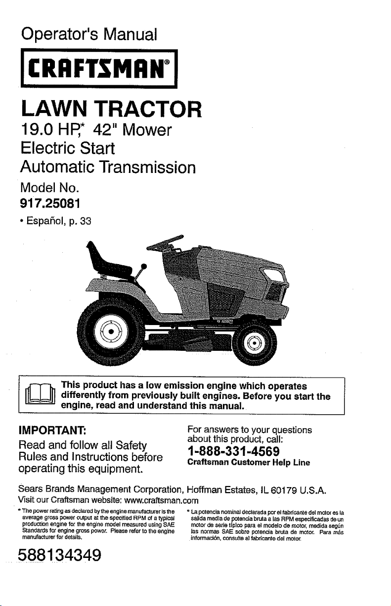
Operator's Manual
19.0 HR* 42" Mower
Electric Start
Automatic Transmission
Model No.
917.25081
• EspaSol, p. 33
I_ his product has a low emission engine which operates
IMPORTANT:
Read and follow atl Safety
Rules and Instructions before
operating this equipment.
Sears Brands Management Corporation, Hoffman Estates, tL 60179 U.S.A.
Visit our Craftsman website: www,craftsman.com
* The powet r_ing as desiared bythe engine manufacturer is the * La potenc_a nominaJ declareda por el fabr_cacte del motor es la
average gross power output at the specked RPM ofa typical ealida medla do potencia brata a los RPM espectficadas de un
production engine for the engine model measured using SAE motor do eerie tfptco pare el modelo de motor, medida eag/,n
Standards for engine gross power. Please refer to the engine los no_mas SAE sob_e potencie br,Jta de motor. Pa,,a m&s
mentJfacturer for details, informacl6n, consu_teal fabdcante del motor.
differently from previously built engines. Before you start the
engine, read and understand this manual.
For answers to your questions
about this product, call:
1-888-331-4569
Craftsman Customer Help Line
588134349
Page 2
Warranty .................................................. 2
Safety Rules ............................................ 3
Product Specifications ............................. 6
Assembly/Pre-Operation ......................... 7
Operation ................................................. 9
Maintenance ........................................... 16
Service and Adjustments ....................... 21
Storage .................................................. 27
Troubleshooting ..................................... 28
Sears Service ......................... Back Cover
Maintenance Schedule .......................... 16
CRAFTSMAN LIMITED WARRANTY
FOR TWO YEARS from the date of purchase, all non-expendable parts of this riding equipment are
warranted against any defects in material or workmanship. With proof of purchase, a defective non-
expendable part will receive free in-home repair or replacement at option of seller.
BATTERY LIMITED WARRANTY
FOR 90 DAYS from the date of purchase, the battery (an expendable part) of this riding equipment is
warranted against any defects in material or workmanship. Wffh proof Of purchase, a new battery will be
supplied free of charge. You are responsible for the labor cost of battery installation,
ADDITIONAL LIMITED WARRANTIES
In the following additional warranties, you are responsible for the tabor cost of part installation after the
second year from the date of purchase.
FOR FIVE YEARS from the date of purchase, the frame of this riding equipment is warranted against any
defects in material or workmanship. With proof of purchase, a new frame wilt be supplied free of charge,
FOR TEN YEARS from the date of purchase, the front axle of this riding equipment is warranted against any
defects in material or workmanship. With proof of purchase, a new front axle will be supplied free of charge.
FOR AS LONG AS IT !S USED by the original owner after the tenth year from the date of purchase, the
cast iron front axle (if equipped) of this riding equipment is warranted against any defects in material or
workmanship. With proof of purchase, a new cast iron front axle will be supplied free of charge.
WARRANTY SERVICE
For warranty coverage details to obtain free repair or replacement, call 1-888-331-4569 or visit the web
page: www.craftsman.com/warranty
In ali cases above, if part repair or replacement is impossibie, the riding equipment will be replaced free of
charge with the same or an equivalent model.
All of the above warranty coverage isvoid if this dding equipment is ever used while providing commercial
services or if rented to another person,
This warranty covers ONLY defects in material and workmanship. Warranty coverage does NOT
include:
• Expendable parts (except battery) that can wear out from normal use within the warranty period, including
but not limited to blades, spark plugs, air cleaners, belts, and oil _ters.
• Standard maintenance servicing, oi] changes, or tune-ups.
• Tirerep_a_ement_rrepaircausedbypuncturesfr_m_utside_bjects_suchasnai_s_th_ms's_umps__rg]ass.
• Tire or wheel replacement or repair resulting from normal wear, accident, or improper operation or
maintenance.
• Repairs necessary because of operator abuse, including but not limited to damage caused by towing
objects beyond the capability of the riding equipment, impacting obiects that bend the frame, axle
assembly or crankshaft, or over-speeding the engine.
• Repairs necessary because of operator negligence, including but not limited to, electricaI and mechanical
damage caused by improper storage, failure to use the proper grade and amount of engine oil, failure
to keep the deck clear of flammable debris, or failure to maintain the riding equipment according to the
instructions contained in the operator's manual.
• Engine (fuel system) cleaning or repairs caused by fuel determined to be contaminated or oxidized
(stale). tn general, fuel should be used within 30 days of its purchase date.
• Normal deterioration and wear of the exterior finishes, or product label replacement.
This warrantygivesyou specific legal dghts, andyoumay alsohaveother rightswhichvaryfromstatetostate.
Sears Brands Management Corporation, Hoffman Estates, IL 60179
2
Page 3
_DANGER: This cutting machine is capable of amputating hands and feet and
throwing objects. Failure to observe the following safety instructions could result
in serious injury or death.
A(_WARNING: Inorderto prevent acciden-
tal starting when setting up, transporting,
adjusting or making repairs, always discon-
nect spark plug wire and place wire where
it cannot contact spark plug.
_WARNING: Do not coast down a hill in
neutral, you may lose control of the tractor.
_WARNING: Tow only the attachments
that are recommended by and comply with
specifications of the manufacturer of your
tractor. Use common sense when towing.
Operate only at the lowest possible speed
when on a slope. Too heavy ofa load, while
on a slope, is dangerous. Tires can lose
traction with the ground and cause you to
lose control of your tractor.
_WARNING: Engine exhaust, some of
itsconstituents, and certain vehicle compo-
nents contain or emit chemicals known to
the State of California to cause cancer and
birth defects or other reproductive harm.
_IbWARNING: Battery posts, terminals and
related accessories contain lead and lead
compounds, chemicals knownto the State of
California to cause cancer and birth defects
or other reproductive harm. Wash hands
after handling.
I. CHILDREN
_(_WARNING! CHILDREN CAN BE IN-
JURED BYTHIS EQUIPMENT. TheAmeri-
can Academy of Pediatrics recommends
that children be a minimum of t2 year of
agebefore operating a pedestrian controlled
lawn mower and a minimum of 16 years of
age before operating a riding lawnmower.
_WARNING! CHILDREN CAN BE
SERIOUSLY INJURED OR KILLED BY
THIS EQUIPMENT. Carefully read and
follow all of the safety instructions below.
Tragic accidents can occur if the operator
is not alert to the presence of children.
Children are oftenattracted to the machine
and the mowing activity. Never assume
that children will remain where you last
saw them.
• Keep children out of the mowing area
and inthe watchfulcare of a responsible
adult other than the operator.
• Be alert and turn machine off if a child
enters the area.
• Before and while backing, look behind
and down for small children.
• Never carry children, even with the
blades shut off. They may fall off and
be seriously injured or interfere with safe
machine operation. Children who have
beengiven ridesinthe past may suddenly
appear in the mowing area for another
ride and be run over or backed over by
the machine.
• Never allow children to operate the ma-
chine.
• Use extreme caution when approaching
blind corners, shrubs, trees, or other
objects that may block your view of a
child,
IL GENERAL OPERATION
- Read, understand, andfo]low all instruc-
tions on the machine and in the manual
before starting.
• Do not put hands or feet near rotating
parts or under the machine, Keep clear
of the discharge opening at all times.
• Only allow responsible adults, who are
familiar with the instructions, to operate
the machine.
• Clearthe area of objects such as rocks,
toys, wire, etc., which could be picked
up and thrown by the blades.
• Ensure the area is clear of bystanders
beforeoperating. Stopmachine ifanyone
enters the area.
• Never carry passengers.
• Do not mowin reverse unless absolutely
necessary. Always look down andbehind
before and while backing,
• Never direct discharged materialtoward
anyone, Avoid discharging material
against a wall or obstruction, Material
may ricochet back toward the operator.
Stop the blades when crossing gravei
surfaces.
• Donot operate machine withoutthe entire
grass catcher, discharge chute, or other
safety devices in place and working.
Page 4
• Slowdown beforetuming.
• Never leave a running machine unat-
tended. Always turn off blades, set
parking brake, stop engine, and remove
keys before dismounting.
• Disengage blades when not mowing.
Shut off engine and wait for all parts to
come to a complete stop before cleaning
the machine, removing the grass catcher,
or unclogging the discharge chute.
• Operate machine onlyin daylightorgood
artificial light.
• Do not operate the machine while under
the influence of alcohol or drugs.
• Watch for traffic when operating near or
crossing roadways.
• Use extreme caution when loading or
unloading the machine into a trailer or
truck.
• Always weareye protection when operat-
ing machine.
• Use ear protectors to avoid damage to
hearing.
• Data indicates that operators, age 60
years and above, are involved ina large
percentage of riding mower-related inju-
ries. These operators should evaluate
their ability to operate the riding mower
safely enough to protect themselves and
others from serious injury.
• Followthe manufacturer's recommenda-
tionfor wheel weights or counterweights.
• Keep machine free of grass, leaves or
other debris build-upwhich cantouch hot
exhaust/engine parts and burn. Do not
allow the mower deck to plow leaves or
other debris which can cause build-up
to occur. Clean any oil or fuel spillage
before operating or storing the machine.
Allow machine to coot before storage.
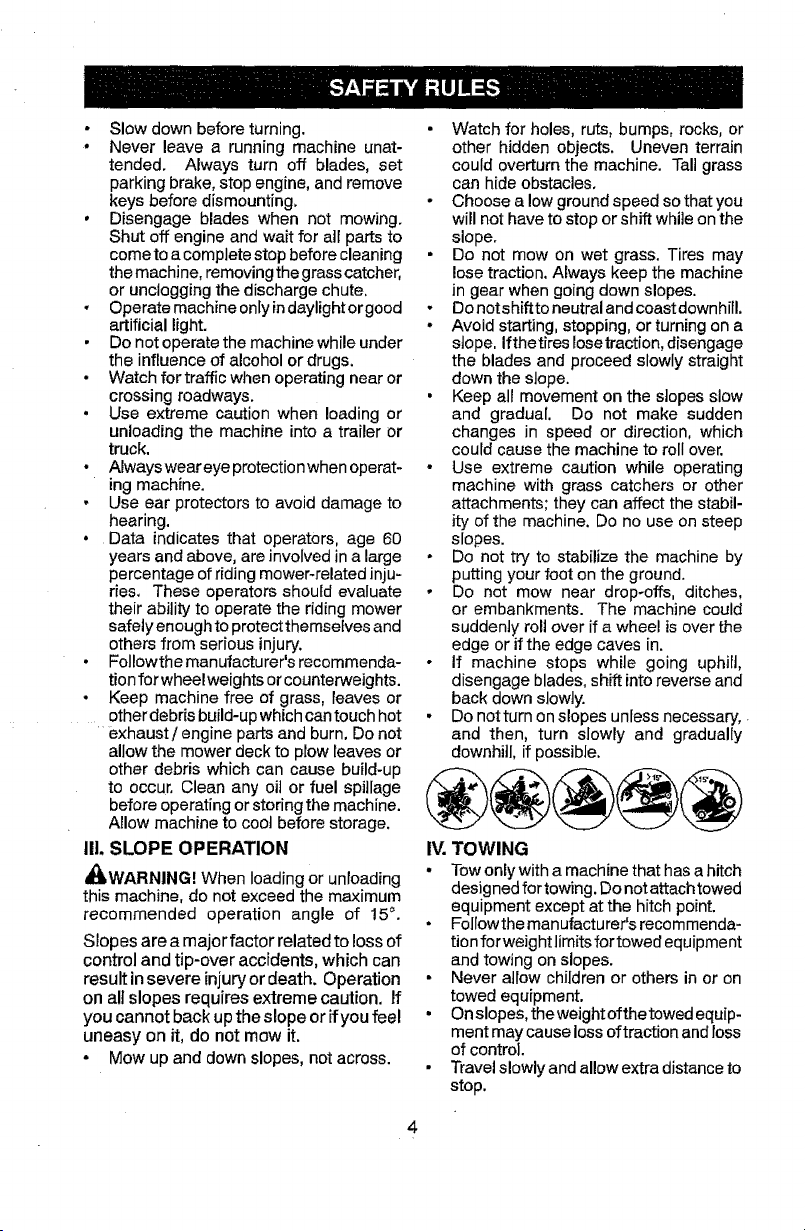
Iil. SLOPE OPERATION
_WARNING! When loading or unloading
this machine, do not exceed the maximum
recommended operation angle of 15°.
Slopes are a major factor related to loss of
control and tip-over accidents, which can
result in severe injury or death. Operation
on all slopes requires extreme caution. If
you cannot back up the slope or ifyou feel
uneasy on it, do not mow it.
- Mow up and down slopes, not across.
• Watch for holes, ruts, bumps, rocks, or
other hidden objects. Uneven terrain
could overturn the machine. Tall grass
can hide obstacles.
• Choose a low ground speed sothat you
will not have to stop or shift while on the
slope.
• Do not mow on wet grass. Tires may
lose traction. Always keep the machine
in gear when going down slopes.
, Do notshiftto neutral andcoastdownhitl.
• Avoid starting, stopping, or turning on a
slope. Ifthetires Iosetraction, disengage
the blades and proceed slowly straight
down the slope.
• Keep all movement on the slopes slow
and gradual. Do not make sudden
changes in speed or direction, which
could cause the machine to roll over.
• Use extreme caution while operating
machine with grass catchers or other
attachments; they can affect the stabil-
ity of the machine. Do no use on steep
slopes.
• Do not try to stabilize the machine by
putting your foot on the ground.
• Do not mow near drop-offs, ditches,
or embankments. The machine could
suddenly roll over if a wheel is over the
edge or if the edge caves in.
• If machine stops while going uphill,
disengage blades, shift into reverse and
back down slowly.
• Do not turn onslopes unless necessary,
and then, turn slowly and gradually
downhill, if possible.
IV. TOWING
• Towonly with a machine that has a hitch
designed for towing. Donot attach towed
equipment except at the hitch point.
• Follow the manufacturer's recommenda-
tion forweight limits for towed equipment
and towing on slopes.
• Never allow children or others in or on
towed equipment.
• On slopes, the weight ofthetowed equip-
ment may cause loss of traction and loss
of control.
• Travel slowly and allow extra distance to
stop.
Page 5
V. SERVICE
SAFE HANDLING OF GASOLINE
To avoid personal injury or property dam-
age, useextreme care in handling gasoline.
Gasoline is extremely flammable and the
vapors are explosive.
• Extinguish all cigarettes, cigars, pipes,
and other sources of ignition.
• Use only approved gasoline container,
• Never remove gas cap or add fuel with
the engine running.
• Allow engine to cool before refueling.
• Never fuel the machine indoors,
• Neverstorethe machineorfuelcontainer
where there is an open flame, spark, or
pilot light such as on a water heater or
other appliances.
• Never fil! containers inside a vehicle or
on a truck or trailer bed with plastic liner.
Always place containers on the ground
away from your vehicle when filling.
- Remove gas-powered equipment from
the truck or trailer and refuel it on the
ground. Ifthis isnot possible, then refuel
such equipmentwith aportable container,
rather than from a gasoline dispenser
nozzle.
• Keep the nozzle in contact with the rim
of the fuel tank or container opening at
all times untilfueling iscomplete. Do not
use a nozzle lock-open device.
• Iffuelis spilled onclothing, change cloth-
ing immediately,
• Never overfill fuel tank. Replace gas cap
and tighten securely.
GENERAL SERVICE
• Never operate machine ina closed area.
• Keep allnutsandbotts tighttoensurethe
equipmentis in safe working condition,
o Nevertamperwithsafe'_tdevices. Never
interferewiththe intendedfunctionof a
safety device or reduce the protection
providedby asafetydevice.Check there
properoperation regularly.NEVER oper-
ate a machine with a safety devicethat
does not function properly.
• Keep machine free of grass, leaves, or
other debris build-up, Clean oil or fuel
spillage and remove any fuel-soaked
debris, Allow machine to cool before
storing.
• If you strike a foreign object, stop and
inspectthemachine. Repair,ifnecessary,
before restarting.
• Never make any adjustments or repairs
with the engine running.
• Checkgrass catchercomponents andthe
discharge chute frequentlyand replace
with manufacturer's recommended parts,
when necessary.
• Mower blades aresharp. Wrapthe blade
orwear gloves, and use extreme caution
when servicing them.
• Checkbrakeoperationfrequently. Adjust
and service as required.
o Maintainor replace safety and instruction
labels, as necessary.
Use ear protectors to avoid damage to hearing.
Always weareye protection when operating machine.
Page 6
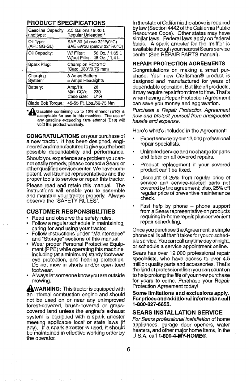
PRODUCTSPECIFICATIONS
Gasoline Capacity 2.5 Gallons 19,46 L
and type: Regular Unleaded *
Oil Type: SAE 30 (above 32°F/0°C)
(APt: SG-SL} SAE 5W30 (below 32°F10°C
Oil Capacity: WI Filter: 56 Oz. ! 1,65 L
Spark Plug: Champion RC12YC
Charging ,3Amps Battery
System: 5 Amps Headlights
Battery: AmplHr: 28
Blade Bolt Torque; 45-55 F_. Lbs./62-75 Nm
&Gasoline containing up to 10% ethanol (El0) is
acceptable for use in this machine, The usa of
any gasoline exceed{ng "_0%ethanol (Et0) will
void the productwarranty,
CONGRATULATIONS on your purchase of
a new tractor. It has been designed, engi-
neered and manufactured to gJveyouthe best
possible dependability and performance.
Should you experience any problem you can-
not easily remedy, please contact a Sears or
other qualified service center. We have com-
petent, well-trained representatives and the
proper tools to service or repair this tractor.
Please read and retain this manual. The
instructions will enable you to assemble
and maintain your tractor properly. Always
observe the "SAFETY RULES".
CUSTOMER RESPONSIBILITIES
• Read and observe the safety rules.
- Follow a regular schedule in maintaining,
caring for and using your tractor.
- Follow instructions under "Maintenance"
and "Storage" sections of this manuaL.
• Wear proper Personal Protective Equip-
ment _PPE)while operating this machine,
including(at a minimum) sturdy footwear,
eye protection, and hearing protection.
Do not mow in shorts and/or open toed
footwear.
• Always letsomeone knowyou areoutside
mowing.
A(_.WARNING: This tractorisequippedwith
an internal combustion engine and should
not be used on or near any unimproved
forest-covered, brush-covered or grass-
covered land unless the engine's exhaust
system is equipped with a spark arrester
meeting applicable local or state laws (if
any). If a spark arrester is used, it should
be maintained in effective working order by
the operator.
W/out Filter: 48 Oz. / 1,4 L
(Gap: ,030"10,76 mm)
Min, CCA: 230
Case size: U1R
Inthe stateof California the above isrequired
bylaw (Section 4442 ofthe California Public
Resources Code), Other states may have
similar laws. Federal laws apply on federal
lands. A spark arrestor for the muffler is
availablethrough your nearest Sears service
center (See REPAIR PARTS manual).
REPAIR PROTECTION AGREEMENTS
Congratulations on making a smart pur-
chase. Your new Craftsman® product is
designed and manufactured for years of
dependable operation. But like all products,
itmay require repairfrom time totime. That's
when havinga Repair ProtectionAgreement
can save you money and aggravation.
Purchase a Repair Protection Agreement
now and protect yourseff from unexpected
hassle and expense.
Herds what's included in the Agreement'.
• Expertservice byour 12,000 professional
repair specialists,
• Unlimited service and no charge for parts
and labor on all covered repairs.
• Product replacement if your covered
product can't be fixed.
• Discount of 25% from regular price of
service and service-related parts not
covered by the agreement; also, 25% off
regular price of preventive maintenance
check.
- Fast help by phone - phone support
from a Sears representative on products
requiring in-home repair, plus convenient
repair scheduling.
Once you #urchasethe Agreement, a simple
phone call is all that it takes for you to sched-
ule service. You can callanytime day or night,
or schedule a service appointment online.
Sears has over 12,000 professional repair
specialists, who have access to over 4.5
million quality parts and accessories. That's
the kind of professionalism you can count on
to help prolong the life of your new purchase
for years to come, Purchase your Repair
Protection Agreement today!
Some limitations and exclusions apply.
For prices and additional information call
1-800-827-6655,
SEARS INSTALLATION SERVICE
For Sears professional installation of home
appliances, garage door openers, water
heaters, and other major home items, in the
U.S.A, call 1-8004-MY-HOME®.
Page 7
Keys
Slope Sheet
(1) Oil Drain Tube
Key(s)
(1) Quick
Connect !
Your new tractor has been assembled at the factory with exception of those parts left
unassembled for shipping purposes.
TOOLS REQUIRED FORASSEMBLY
A socket wrench set will make assembly
easier. Standard wrench sizes are listed.
(1) 1/2" wrench Tire pressure gauge
(2) 7/t6" wrenches Utility knife
Pliers
When right or left hand is mentioned in this
manual,itmeanswhenyouareintheoperating
position (seated behind the steering wheel).
TO REMOVE TRACTOR FROM
CARTON
UNPACK CARTON
• Remove all accessible loose parts and
parts cartons from carton.
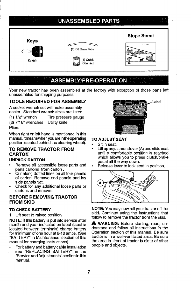
TO ADJUST SEAT
• Sit in seat.
• LAup adjustment lever (A) andslideseat
until a comfortable position is reached
which allows you to press clutch/brake
pedal all the way down.
• Release lever to lock seat in position,
- Cut along dotted lines on all four panels
of carton. Remove end panels and lay
side panels flat.
• Check for any additional loose parts or
cartons and remove.
BEFORE REMOVING TRACTOR
FROM SKID
TO CHECK BATTERY
1, Liftseat to raised position.
NOTE: Ifthis battery is put into service after
month and year indicated on label (label is
located between terminals) charge battery
for minimum of one hour at 6-10 amps. (See
"BATTERY" in Maintenance section of this
manual for charging instructions).
• For battery and battery cable installation
see "REPLACING BATTERY" in the
"Service and Adjustments" section in this
manual.
NOTE: You may now roll your tractor off the
skid. Continue using the instructionsthat
follow to remove the tractor from the skid.
WARNING: Before starting, read, un-
derstand and follow all instructions in the
Operation section of this manual. Be sure
tractor is in a well-ventilated area. Be sure
the area in front of tractor is clear of other
people and objects.
Page 8
TO ROLL TRACTOR OFF SKID (See
Operation section for location and
function of controls)
1. Raise attachment liftlever to itshighest
position.
2. Release parking brake by depressing
clutch/brake pedal.
S. Place freewheel control Jn"transmission
disengaged position" (See "TO TRANS =
PORT" in the Operation section o1this
manual).
4. Roll tractor forward off skid.
5. Remove banding holding the deflector
shield up against tractor.
Continue with the instructionsthat follow.
CHECK TIRE PRESSURE
The tires onyourtractor were overlnflatedat
the factory for shipping purposes. Correct
tire pressure is important for best cutting
performance.
• Reduce tire pressure to PSI shown on
tires.
CHECK DECK LEVELNESS
For best cutting results, mower housing
should be properly leveled. See "TO LEVEL
MOWER" in the Service and Adjustments
section of this manual.
CHECK FOR PROPER POSITION OF
ALL BELTS
See the figures that are shown for replacing
motion and mower blade drive belts in the
Service and Adjustments sectionofthis man-
ual. Veriiy that the belts are routed correctly.
CHECK BRAKE SYSTEM
After you learn how to operate your tractor,
check to see that the brake is operating
properly. See 'q'O CHECK BRAKE" in the
Service and Adjustments section of this
manual.
V(CHECKLIST
Before you operate your new tractor, we
wish to assure that you receive the best
performance and satisfaction from this
Quality Product.
Please review the following checklist:
V"All assembly instructions have been
completed.
J" No remaining loose parts in carton.
v/ Battery isproperly prepared andcharged.
J" Seat is adjusted comfortably and tight-
ened securely.
d' All tires are properly inflated. (For ship-
ping purposes,the tires were overinflated
at the factory).
J Ensure mower deck is propedy leveled
side-to-side/front-to-rear for best cutting
results. (Tires must be propedy inflated
for leveling).
J" Check mower and drive belts. Ensure
they are routed properly around pulleys
and inside alt belt keepers.
d" Checkwiring. Seethatall connections are
stillsecureandwiresareproperiyclamped.
J Before driving tractor, besure freewheel
control isin "transmission engaged" posi-
tion (see "ToTransport" in the Operation
section of this manual).
While learninghowto useyourtractor,payex-
traattentiontothe following importantitems:
d" Engine oil is at proper level.
vf Fueltank isfilledwith fresh, clean, regular
unleaded gasoline.
#' Become familiar with all controls, their
location and function. Operate them
before you start the engine.
t/Ensure brake system isin safe operating
condition.
!/Ensure Operator Presence System and
Reverse Operation System (ROS) are
working properly (SeetheOperation and
Maintenance sections in this manual).
Page 9
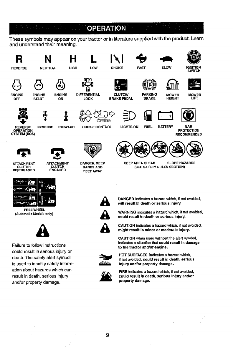
Thesesymbolsmayappearonyourtractororinliteraturesuppliedwiththeproduct.Learn
andunderstandtheirmeaning.
R N H Ikl
REVERSE NEUTRAL HIGH LOW CHOKE IGNITION
FAST SLOW
SWITCH
ENGINE ENGINE ENGINE DIFFERENTIAL
OFF START ON LOCK
1'114
q_
,I;
€
REVERSE
OPERATION
SYSTEM (ROS)
ATTACHMENT ATTACHMENT DANGER, KEEP
CLUTCH CLUTCH HANDS AND
DISENGAGED ENGAGED FEET AWAY
(Automatic Models only)
REVERSE FORWARD CRUISE CONTROL LIGHTS ON FUEL BATTERY EAR
FREEWHEEL
&
Failure to follow instructions
couldresult in serious injure/or
death. The safety alert symbol
is used to identify safety inform-
ation about hazards which can
result indeath, serious injury
and/or property damage.
CLUTCH/ MOWER
BRAKE PEDAL LIFT
PARKING MOWER
BRAKE HEIGHT
RECOMMENDED
®@@@@
KEEP AREA CLEAR SLOPE HAZARDS
(SEE SAFETY RULES SECTION)
&
&
&
DANGER indicates a hazard which, if not avoEded,
will result In death or serious injury.
WARNING indicates a hazard which, if not avoided,
could Pesult tn death or serious injury.
CAUTION indicates a hazard which, if not avoided,
might result in minor or moderate intury.
CAUTION when used without the aled symbol.
indicates a situation that could result in damage
to the tractor and/or engine,
HOT SURFACES indicates a hazard which,
if not avoided, could result in death, serious
injury and/or property damage.
FIRE indicates a hazard which, if not avoided,
could result In death, serious injury and/or
property damage.
PROTECTION
• 9
Page 10
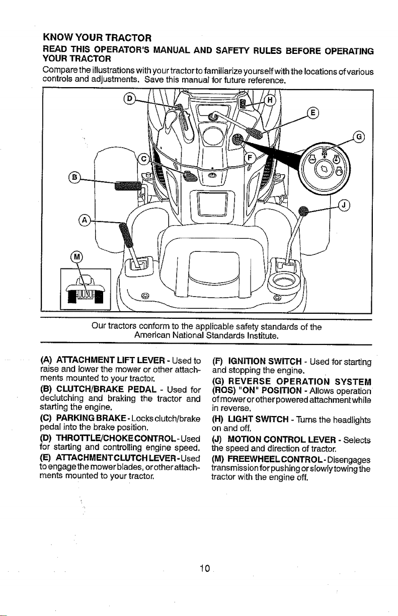
KNOW YOUR TRACTOR
READ THIS OPERATOR'S MANUAL AND SAFETY RULES BEFORE OPERATING
YOUR TRACTOR
Compare the illustrations withyour tractorto familiarize yourself with the locationsofvarious
controls and adjustments. Save this manual for future reference.
/_ \"_
Our tractors conform to the applicable safety standards of the
American National Standards Institute.
(A) ATTACHMENT LIFT LEVER - Used to
raise and lower the mower or other attach-
merits mounted to your tractor.
(B) CLUTCH/BRAKE PEDAL - Used for
declutching and braking the tractor and
starting the engine.
(C) PARKING BRAKE- Locks dutch/brake
pedal into the brake position.
(D) THROTtLE/CHOKE CONTROL- Used
for starting and controlling engine speed.
(E) ATTACHMENTCLUTCH LEVER- Used
toengagethe mower blades, orother attach-
ments mounted to your tractor.
(F) IGNITION SWITCH - Used for starting
and stopping the engine.
(G) REVERSE OPERATION SYSTEM
(ROS) "ON" POSITION - Allows operation
ofmower orother powered attachment while
in reverse.
(H) LIGHT SWITCH - Turnsthe headlights
on and off.
(J) MOTION CONTROL LEVER - Selects
the speed and direction of tractor,
(M) FREEWHEEL CONTROL- Disengages
transmission for pushing ors[owlytowing the
tractor with the engine off.
t0
Page 11
The operation of any tractor can result in foreign objects thrown into
the eyes, which can result in severe eye damage. Always wear safety
glasses or eye shields while operating your tractor or performing any
adjustments or repairs. We recommend standard safety glasses or a
wide vision safety mask worn over spectacles.
HOW TO USE YOUR TRACTOR
TO SET PARKING BRAKE
Your tractor is equipped with an operator
presence sensing switch. When engine
is running, any attempt by the operator to
leavethe seat withoutfirst setting the parking
brake wilt shut off the engine.
1. Depress clutch/brake pedal (B) all the
way down and hold.
2, Pult parking brake lever (C) up and hold,
release pressure from clutch/brake pedal
(B), then release parking brake lever.
Pedal should remain in brake position,
Ensure parking brake will hold tractor
secure.
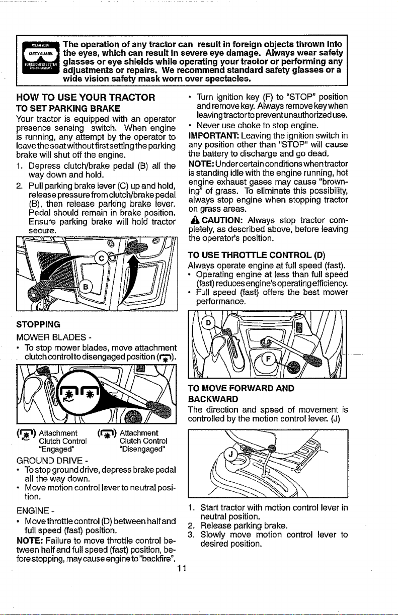
STOPPING
MOWER BLADES -
• To stop mower blades, move attachment
clutch controlto disengaged position (t_).
(1"_11)Attachment (tr_l) Attachment
Clutch Control Clutch Control
"Engaged .... Disengaged"
GROUND DRIVE -
• To stop ground drive, depress brake pedal
all the way down,
• Move motion control lever to neutral posi-
tion.
ENGINE -
• Movethrottle control (D)between halfand
full speed (fast) position.
NOTE: Failure to move throttle control be-
tween half and full speed (fast) position,be-
forestopping, may causeengineto"backfire".
• Turn ignitionkey (F) to "STOP" position
andremove key.Always remove keywhen
leavingtractorto preventunauthorized use.
• Never use choke to stop engine.
IMPORTANT: Leavingthe ignitionswitch in
any position other than "STOP" will cause
the battery to discharge and go dead.
NOTE: Undercertain conditions whentractor
is standing idle with the engine running, hot
engine exhaust gases may cause "brown-
ing" of grass. To eliminate this possibility,
always stop engine when stoppingtractor
on grass areas.
A CAUTION: Always stop tractor com-
pletely, as described above, before leaving
the operator's position.
TO USE THROTTLE CONTROL (D)
Always operate engine at full speed (fast).
• Operating engine at less than full speed
(fast)reducesengine'soperating efficiency.
• Full speed (fast) offers the best mower
performance.
TO MOVE FORWARD AND
BACKWARD
The direction and speed of movement is
controlled by the motion control lever, (J)
1. Start tractor with motion control lever in
neutralposition.
2. Release parking brake.
3. Slowly move motion control lever to
desired position.
11
Page 12
TO ADJUST MOWER CUTTING HEIGHT
The position ofthe attachment liftlever (A)
determines the cutting height.
° Put attachment lift lever in desired cutting
height slot.
The cutting height range is approximately 1
to 4" (25,4 to 101,6 ram)..The heights are
measured from the ground to the blade tip
with the engine not running. These heights
are approximate and may vary depending
upon soil conditions, height of grass and
types of grass being mowed.
• The average lawnshould becutto approxi-
mately 2-1/2" (63,5 mm) during the cool
season and to over 3" (76,2 mm) during
hot months. For healthier and better look-
ing lawns, mow often and after moderate
growth.
• For best cutting performance, grass over
6" (152,4 ram) in height should bemowed
twice. Make the first cut relatively high; the
second to desired height.
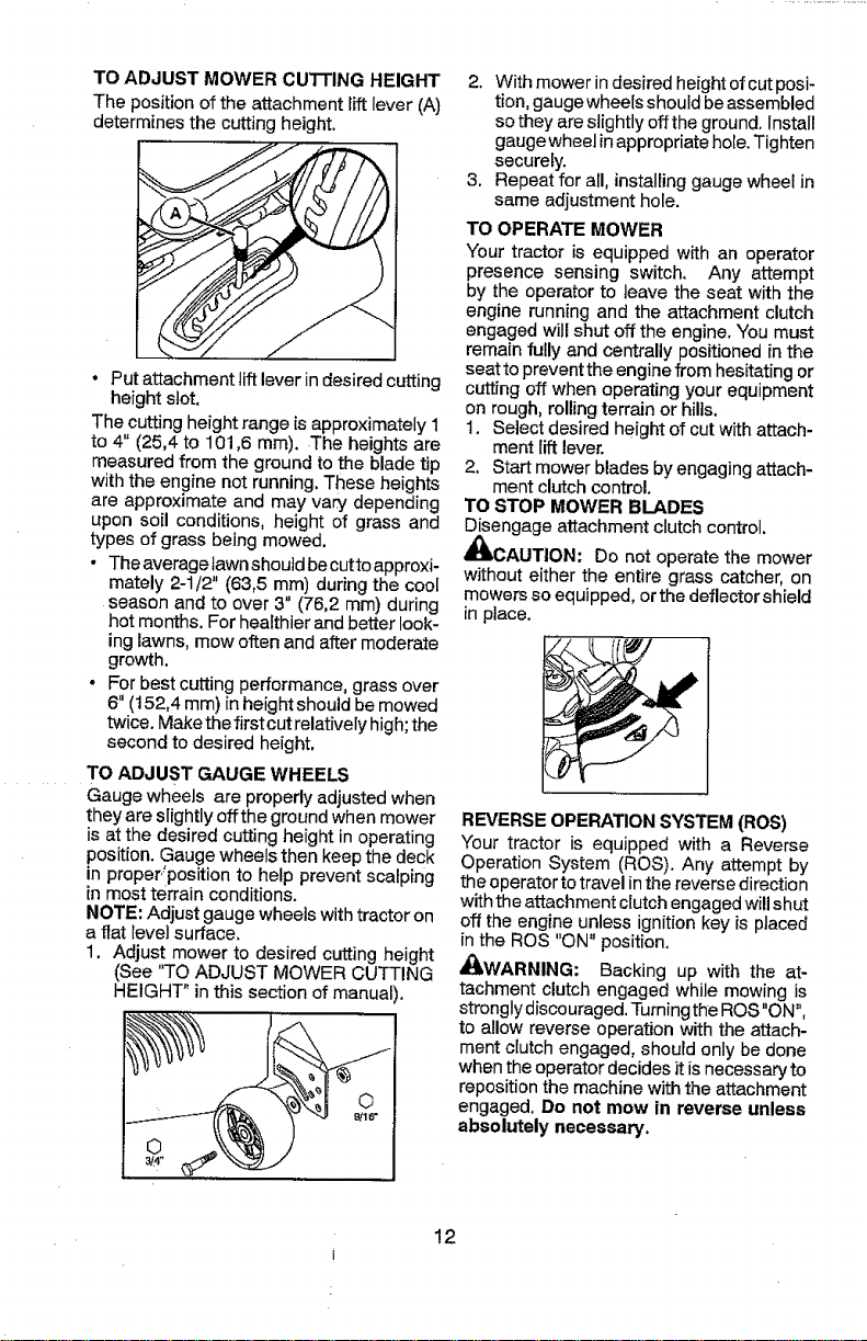
TO ADJUST GAUGE WHEELS
Gauge wheels are properly adjusted when
theyare slightly offthe ground when mower
is at the desired cutting height in operating
position. Gauge wheels then keep the deck
in proper/position to help prevent scalping
in most terrain conditions.
NOTE: Adjust gauge wheels with tractor on
a fiat leve_surface,
1. Adjust mower to desired cutting height
(See "TO ADJUST MOWER CUTTING
HEIGHT" in this section of manual).
2. With mower indesired height of cutposi-
tion, gauge wheeis shouId be assembled
sothey are slightly off the ground. Install
gauge wheel inappropriate hole. Tighten
securely.
3. Repeat for all, installing gauge wheel in
same adjustment hole.
TO OPERATE MOWER
Your tractor is equipped with an operator
presence sensing switch. Any attempt
by the operator to leave the seat with the
engine running and the attachment clutch
engaged will shut off the engine. You must
remain fully and centrallypositioned in the
seatto prevent the engine fTOmhesitating or
cutting off when operating your equipment
on rough, rolling terrain or hills.
1. Select desired height of cut with attach-
ment lift lever.
2, Start mower blades byengaging attach-
ment clutch control.
TO STOP MOWER BLADES
Disengage attachment clutch control.
_CAUTION: Do not operate the mower
without either the entire grass catcher, on
mowers so equipped, orthe deflector shield
in place.
REVERSE OPERATION SYSTEM (ROS)
Your tractor is equipped with a Reverse
Operation System (ROS). Any attempt by
the operator to travel inthe reverse direction
with the attachment clutch engaged will shut
off the engine unless ignition key is placed
in the ROS "ON" position.
all'WARNING: Backing up with the at-
tachment clutch engaged while mowing is
stronglydiscouraged, Turningthe ROS"ON",
to allow reverse operation with the attach-
ment clutch engaged, should only be done
when the operator decides it is necessary to
reposition the machine w_ththe attachment
engaged, Do not mow in reverse unless
absolutely necessary,
12
Page 13
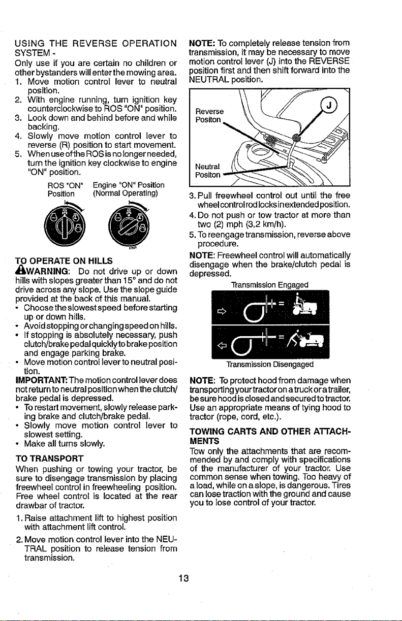
USINGTHEREVERSEOPERATION
SYSTEM-
Onlyuseifyouarecertainnochildrenor
otherbystanderswillenterthemowingarea.
1.Movemotioncontrollevertoneutral
position.
2.Withenginerunning,turnignitionkey
counterclockwisetoROS"ON"position,
3. Lookdownandbehindbeforeandwhile
backing,
4. Slowlymovemotioncontrolleverto
reverse(R)positiontostartmovement.
5,WhenuseoftheROSisnolongerneeded,
turntheignitionkeyclockwisetoengine
"ON"position.
ROS"ON"Engine"ON"Position
Position(NormalOperating)
TO OPERATE ON HILLS
_WARNING: Do not drive up or down
hills with slopes greater than 15° and do not
drive across any slope. Use the slope guide
provided at the back of this manual.
• Choosetheslowestspeed before starting
up or down hills.
- Avoid stopping or changing speed onhills.
• If stopping is absolutely necessary, push
clutch/brake pedalquickly tobrake position
and engage parking brake.
• Move motion control teverto neutral posi-
tion.
IMPORTANT: The motion control lever does
not return toneutral positionwhenthe clutch/
brake pedal is depressed.
• To restart movement, slowly release park-
ing brake and clutch/brake pedal.
• Slowly move motion control lever to
slowest setting,
- Make all turns slowly.
TO TRANSPORT
When pushing or towing your tractor, be
sure to disengage transmission by placing
freewheel control in freewheeling position.
Free wheel control is located at the rear
drawbar of tractor.
1.Raise attachment lift to highest position
with attachment lift control.
2. Move motion control lever into the NEU-
TRAL position to release tension from
transmission.
NOTE: To completely release tension from
transmission,it may be necessary to move
motion control lever (J) into the REVERSE
position first and then shift forward into the
NEUTRAL position.
Neutral (__..zL-...'%.
Pos.o.
3.Pull freewheel control out until the free
wheelcontrolrodlocksinextendedposition.
4.Do not push or tow tractor at more than
two (2) mph (3,2 kin/h).
5.Toreengage transmission, reverse above
procedure.
NOTE: Freewheel control will automatically
disengage when the brake/clutch pedal is
depressed.
TransmissionEngaged
Transmission Disengaged
NOTE: Toprotecthoodfrom damage when
transporting yourtractoron atruck oratrailer,
besure hood isclosedand secured to tractor.
Use an appropriate means of tying hood to
tractor (rope, cord, etc.).
TOWING CARTS AND OTHER A'rrACH-
MENTS
Tow only the attachments that are recom-
mended by and complywith specifications
of the manufacturer of your tractor, Use
common sense when towing. Tooheavy of
aload, whileona slope, isdangerous.Tires
can losetractionwiththe ground and cause
you tolose controlofyour tractor.
13
Page 14
BEFORE STARTING THE ENGINE
CHECK ENGINE OIL LEVEL
The engine in yourtractor hasbeen shipped
from the factory already filled with summer
weight oil.
1. Check engine oil with tractor on level
ground.
2. Remove oil fill cap/dipstick and wipe
clean, reinsertthe dipstick and screw cap
tight, wait for afew seconds, remove and
read oil level, ff necessary,, add oil until
"FULl" mark on dipstick is reached. Do
not overfill.
• For cold weather operation you should
change oil for easier starting (See the oil
viscosity chart inthe Maintenance section
of this manual).
• Tochangeengine oil,seethe Maintenance
section in this manual.
ADD GASOLINE
• Fill fuel tank to bottom of filler neck. Do
not overfill.. Use fresh, clean, regular
gasoline with a minimum of 87 octane.
Do not mix oil with gasoline, Purchase
fuel in quantities that can be used within
0 days to ensure fuel freshness.
CAUTION: Wipe offany spilled oil orfuel.
Do not store, spill or use gasoline near an
open flame:
IMPORTANT: When operating intempera-
tures below 32°F (0°C), use fresh, clean
winter grade gasoline to help ensure good
cold weather starting,
CAUTION: Alcohol blended fuels (called
gasohol or using ethanol or methanol) can
attract moisture which leads to separation
andformation of acids during storage. Acidic
gas candamagethe fuel system of anengine
while in storage, To avoid engine problems,
the fuel system should be emptied before
storage of 30 days or longer. Drain the gas
tank, start the engine and let it run until the
fuel lines and carburetor are empty. Use
fresh fuel nextseason. See Storage Instruc-
tions for additional information. Never use
engine or carburetor cleaner products in the
fuel tank or permanent damage may occur.
Fuelstabilizer isanacceptable alternative in
minimizingthe formation offuel gum deposits
during storage. Add stabilizer to gasoline in
fuel tank or storage container. Always follow
the mix ratio found on stabilizer container.
Run engine at least 10 minutes after adding
stabilizer to allow the stabilizer to reach the
carburetor. Do not empty the gas tank and
carburetor if using fuel stabilizer.
TO START ENGINE
When starting the engine for the firsttime or
if the engine has run out of fuel, it will take
extra cranking time to move fuel from the
tank to the engine.
1. Ensure freewheel control is in the trans-
mission engaged position,
2. Sitonseat inoperating position, depress
clutch!brake pedal and setparking brake.
3. Place motion control lever in neutral
position.
4. Move attachment clutch to disengaged
position.
5. Movethrottle control to choke position.
NOTE: Before starting, read the warm and
cold starting procedures below.
6. Insert key into ignition and turn key
clockwise to start position and release
key as soon as engine starts. Donot run
starter continuously for more than fifteen
seconds per minute, If the engine does
not start after several attempts, move
throttle control to fast position, wait a
few minutes and try again. If engine still
does notstart, move the throttle control
back to the choke position and retry.
WARM WEATHER STARTING
(50°F (10°C) and above)
7. When engine starts, move the throttle
control to the fast position,
° The attachments and ground drive
can now be used. If the engine does
not accept the load, restart the engine
and allow itto warm upfor oneminute
using the choke as described above.
COLD WEATHER STARTING
(50°F (10°C) and below)
7. When engine starts, leavethrottle control
in choke position until engine warms up
and begins to run roughly. Once rough
running begins, immediately move the
throttle controltothe fast position. Engine
warm-up maytake from several seconds
to several minutes (the colder the tem-
perature, the longer the warm-up).
AUTOMATIC TRANSMISSION WARM UP
Before driving the unit in cold weather, the
transmission should be warmed up as fol-
lows:
1. Ensure the tractor is on level ground.
2. Place the motion control lever in neutral
Release the parking broke and let the
clutch/brake slowly return to operating
position.
14
Page 15
3.AIIowoneminutefortransmissiontowarm
up.Thiscanbedoneduringtheengine
warmupperiod.
• Theattachmentscanalsobeuseddur-
ingtheenginewarm-upperiodafterthe
transmissionhasbeenwarmedup.
MOWING TIPS
• DO NOT use tire chains when the mower
housing is attached to tractor.
• Mower should be properly leveled for best
mowing performance. See "TO LEVEL
MOWER HOUSING" in the Service and
Adjustments section of this manual.
• The left hand side of mower should be
used fortrimming.
• Drive sothat clippings are discharged onto
the area that has already been cut. Have
the cutarea to the right ofthe tractor. This
will result in a more even distribution of
clippings and more uniform cutting.
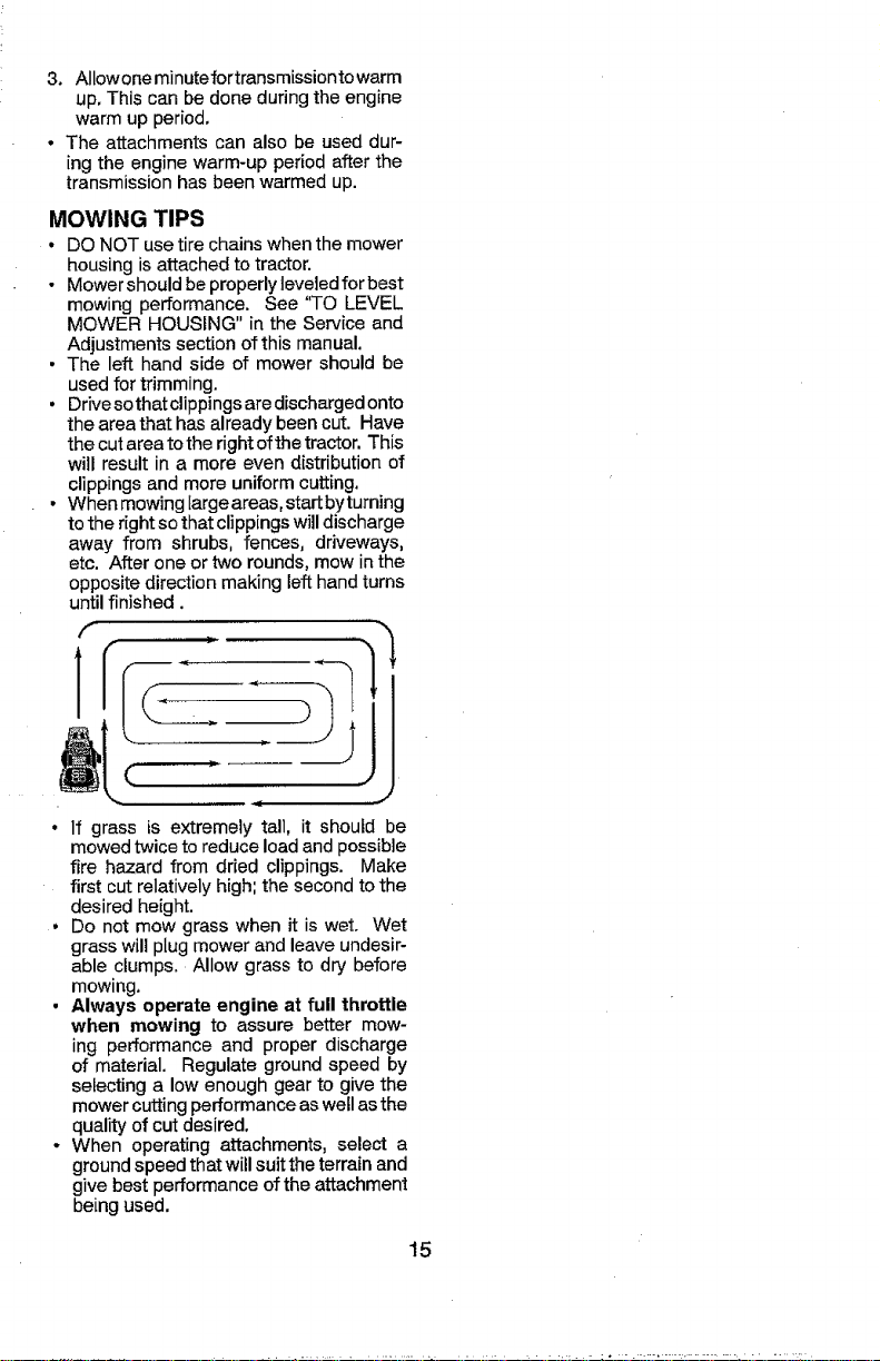
• When mowing largeareas, start byturning
to the right so that clippings will discharge
away from shrubs, fences, driveways,
etc. After one or two rounds, mow in the
opposite direction making left hand turns
until finished.
Z"
_ J
• If grass is extremely tall, it should be
mowed twice to reduce load and possible
fire hazard from dried clippings. Make
first cut relatively high; the second to the
desired height.
• Do not mow grass when it is wet. Wet
grass will plug mower and leave undesir-
able clumps. Allow grass to dry before
mowing.
• Always operate engine at full throttle
when mowing to assure better mow-
ing performance and proper discharge
of material. Regulate ground speed by
selecting a low enough gear to give the
mower cutting performance as well as the
quality of cut desired.
o When operating attachments, select a
ground speed that will suit the terrain and
give best performance of the attachment
being used.
15
Page 16
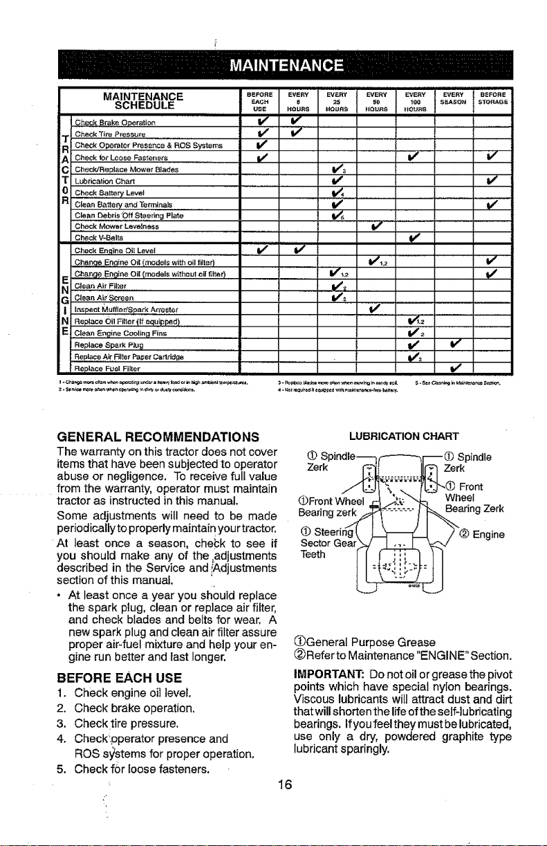
MAINTENANCE eEFOnE
SCHEDULE _c.
Check Brake Op,erafien
Check Tire Pressure ......... V'
T Check Operator Presence & ROS Systems I_'
A Check for Loose Fasteners
C CheeWReplace Mower Blades ......
T Lubrication Chart
0 Check 8attery Level
R Clean Battery and Terminals .........................
ull i i
USE
CleanDebrisO!.!...st_r!ngPla_
.Check Mower Levelness ..............
Check V-Belts
Check Engine eli Level .If
Change Engin # Oil Imodels with oil filter)
Chan£te.Engtne Oil Imodels without oil filter)
_ Clean Air Filt,itr ...............
G risenAl_Screen
I Inspect _luffl_r/Spark Attester .
N Re place Oil Filter (If equipped ) ........
E ,,C!eacEngine Cooling Fins
Replace Spark Plug .............
Replace Air Filter Paper Cartridge
.. R.eplace Fuel Filter ..................................
,lll,l,UHIII,Ul
EVE_ EV_aV _SaY '&_;
8 25 _O 100
_OURS HOSES SOURS SOURS
v
i,,"
V's
V' V'
v' v"
nl v,
v',
v'
V_
EVERY BEFORE
S_.ASON STOOGE
GENERAL RECOMMENDATIONS
The warranty on this tractor does not cover
items that have been subjected to operator
abuse or negligence, To receive full value
from the warranty, operator must maintain
tractor as instructedin this manual.
Some adjustments will need to be made
periodically to properly maintain your tractor.
At least once a season, chebk to see if
you should make any of the ,adjustments
described in the Service and iAdjustments
section of this manual.
* At least once a year you should replace
the spark plug, clean or replace air filter,
and check blades and belts for wear. A
new spark plug and clean air filter assure
proper air-fuel mixture and help your en-
gine run better and lastlonger.
BEFORE EACH USE
1. Check engine oil level.
2. Check brake operation.
3, Checktire pressure,
4. Check!pperator presence and
ROS sy'stems for proper operation,
5. Check for loosefasteners.
LUBRICATION CHART
Spindle---_ F----'--ql_ _ Spindle
Zerk _'_. __._,:_:_Zerk
//]__J_;_"%--L --f 'ij"-(_ Front
l_FrontWheel r_ _5:'_ Wheel
Steering[ _ / @ Enaine
SectorGear_ -,_L:_z:_L-'_',/
Teeth _!_,! i!_._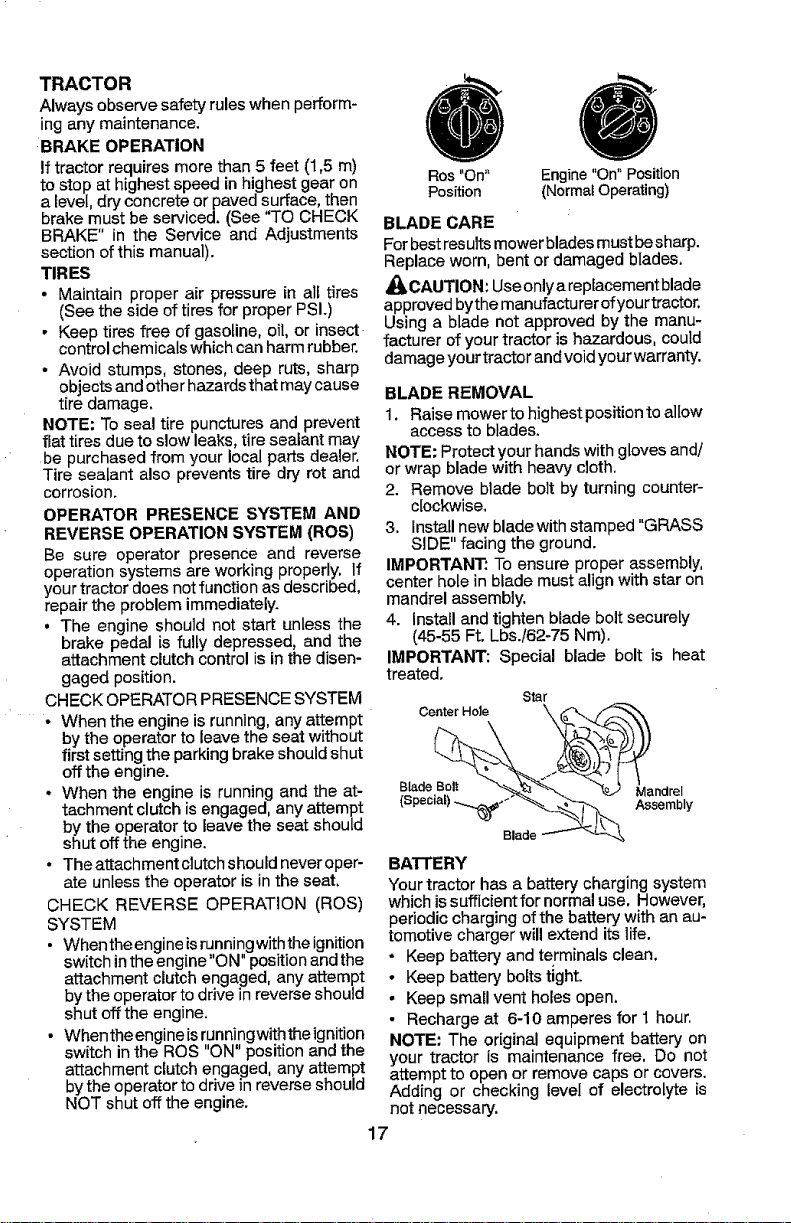
TRACTOR
Always observe safety rules when perform-
ing any maintenance.
BRAKE OPERATION
if tractor requires morethan 5 feet (1,5 m)
to stop at highest speed inhighest gear on
a level, dry concrete or paved surface, then
brake must be serviced. _See"TO CHECK
BRAKE" in the Service and Adjustments
section of this manual).
TIRES
• Maintain proper air pressure in all tires
(See the side of tires for proper PSL)
o Keep tires free of gasoline, oil, or insect
control chemicals which can harm rubber.
• Avoid stumps, stones, deep ruts, sharp
objects and other hazards that may cause
tire damage.
NOTE: To seal tire punctures and prevent
fiat tires due to slow leaks, tire sealant may
be purchased from yourlocal parts dealer.
Tire sealant also prevents tire dry rot and
corrosion.
OPERATOR PRESENCE SYSTEM AND
REVERSE OPERATION SYSTEM (ROS)
Be sure operator presence and reverse
operation systems are workingproperly. If
your tractor does not function as described,
repair the problem immediately.
• The engine should not start unless the
brake pedal is fully depressed, and the
attachment clutch control is in the disen-
gaged position.
CHECK OPERATOR PRESENCE SYSTEM
• When the engine is running, anyattempt
by the operator to leavethe seat without
first settingthe parking brake should shut
off the engine.
- When the engine is running and the at-
tachment clutch is engaged, any attempt
by the operator to leave the seat should
shutoff the engine.
• The attachment clutch should never oper-
ate unless the operator is inthe seat.
CHECK REVERSE OPERATION (ROS)
SYSTEM
• When the engineisrunning withthe ignition
switch in the engine"ON" position and the
attachment clutch engaged, anyattempt
bythe operator to drive in reverse should
shut off the engine,
• When the engineisrunningwiththe ignition
switch in the ROS "ON" position and the
attachment clutch engaged, any attempt
bythe operator to drive in reverse should
NOT shut off the engine.
Ros "On" Engine "On" Position
Position (Normal Operating)
BLADE CARE
Forbest resultsmower blades must besharp.
Replace worn, bent or damaged blades.
_IbCAUTION: Use onlya replacement blade
approvedbythe manufacturer ofyourtractor.
Using a blade not approved by the manu-
facturer of your tractor is hazardous, could
damage your tractor and void your warranty.
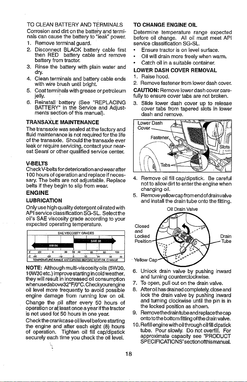
BLADE REMOVAL
1. Raise mower to highest position to allow
access to blades.
NOTE: Protect your hands with gloves and/
or wrap blade with heavy cloth,
2. Remove blade bolt by turningcounter-
clockwise.
3. Install new blade with stamped "GRASS
SIDE" facing the ground.
IMPORTANT: To ensure proper assembly,
center hole in blade must align with star on
mandrel assembly.
4. Install and tighten blade bolt securely
(45-55 Ft. Lbs./62-75 Nm).
IMPORTANT: Special blade bolt is heat
treated.
Canter Hole
Star
BATTERY
Your tractor has a battery charging system
which issufficient for normal use. However,
periodic charging of the battery with an au-
tomotivecharger will extend its life.
- Keep battery and terminals clean.
• Keep battery bolts tight.
• Keep small vent holes open.
• Recharge at 6-10 amperes for I hour.
NOTE: The original equipment battery on
your tractor is maintenance free, Do not
attempt to open or remove capsor covers.
Adding or checking level of electrolyte is
not necessary.
17
Page 18
TO CLEAN BATTERY AND TERMINALS
Corrosion and dirt on the battei'y and termi-
nals can cause the battery to ,leak" power.
1, Remove terminal guard.
2. Disconnect BLACK battery cable first
then RED battery cable and remove
battery from tractor.
3, Rinse the battery with plain water and
dry.
4. Clean terminals and battery cable ends
with wire brush until bright.
5. Coat termihals with grease or petroleum
jelly.
6, Reinstallbattery (See "REPLACING
BATTERY" in the Service and Adjust-
ments !section of this manual).
TRANSAXLE MAINTENANCE
The transaxlewas sealed at the factory and
fluid maintenance is not required for the life
ofthe transaxle. Should the transaxle ever
leak or require servicing, contact your near-
est Sears or other qualified service center.
V-BELTS
Check V-beltsfor deterioration andwearafter
100hours ofoperation and replace if neces-
sary, The belts are not adjustable. Replace
belts if they begin to slip from wear.
ENGINE
LUBRICATION
Only use high quality detergent oilrated with
API service classification SG-SL. Selectthe
oil's SAE viscosity grade according to your
expected operating temperature.
TO CHANGE ENGINE OIL
Determine temperature range expected
before oil change. All oil must meet AP[
service classification SG-SL
• Ensure tractor is on level surface.
• Oil will drain more freely when warm,
• Catch oil in a suitable container.
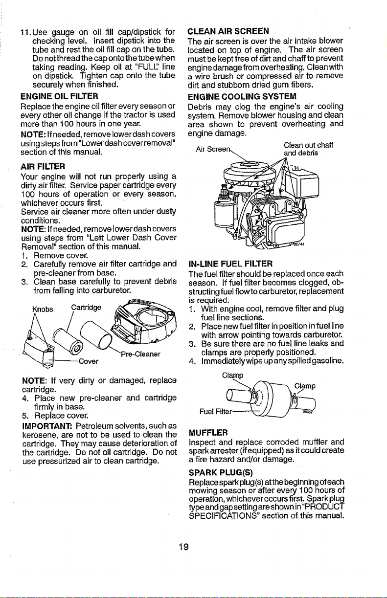
LOWER DASH COVER REMOVAL
1. Raise hood.
2. Remove fastener from lower dash cover,
CAUTION: Remove lower dash cover care-
fully to ensure cover tabs are notbroken.
3. Slide lower dash cover up to release
cover tabs from tapered slots in lower
dash and remove.
LowerDash
4. Remove oil fill cap/dipstick. Be careful
nottoallow dirt to enter the engine when
changing oil.
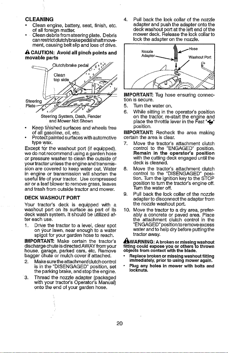
5. RemoveyeUowcapfromendofdrainvalve
and install the drain tube ontothe fitting.
OilDrainValve
NOTE: Although multi-viscosity oils (5W30,
10W30 etc,) improvestarting incoldweather,
they will result in increased oil consumption
whenusedabove32°F/0°C.Checkyourengine
oil level more frequently to avoid possible
engine damage from running low on oil.
Change the ,oil after every 50 hours of
operation orat..least oncea year ifthe tractor
isnot used fo_50 hours inone year,
Checkthe crarikcase oillevel before starting
the engine .and after each eight (8) hours
of operation. Tighten oil fill cap/dipstick
securely each time you check the oil level.
Tube
6. Unlock drain vafve by pushing inward
and turning counterclockwise.
7, To open, putl outon the drain valve.
8. After oilhasdrained completely,closeand
tock the drain valve by pushing inward
and turning clockwise until the pin is in
the locked position as shown,
9, Removethedraintubeand replacethecap
ontoto the bottomfitting ofthe drainvalve.
10, Refilfengine with oilthrough oilfilldipstick
tube. Pour slowly. Do not overfill, For
approximate capacity see "PRODUCT
SPECIFICATIONS"sectIonofthismanual,
18
Page 19
11.Use gauge on oil fill cap/dipstick for
checking level. Insert dipstick into the
tube and restthe oil fill cap on the tube.
Do notthread the capontothe tube when
taking reading. Keep oil at "FULL' line
on dipstick. Tighten cap onto the tube
securely when finished.
ENGINE OIL FILTER
Replace the engine oil filter every season or
every other oil change if the tractor is used
more than 100 hours in one year.
NOTE: If needed, remove lower dashcovers
using stepsfrom"Lowerdash cover removal"
section of this manual.
AIR FILTER
Your engine will not run properly using a
dirty airfilter. Service paper cartridge every
100 hours of operation or every season,
whichever occurs first.
Service air cleaner more often under dusty
conditions.
NOTE: If needed, remove lower dash covers
using steps from "Left Lower Dash Cover
Removal" section of this manual.
1. Remove cover,
2, Carefully remove a_irfilter cartridge and
pre-cleaner from base.
3. Clean base carefully to prevent debris
from falling into carburetor.
NOTE: If very dirty or damaged, replace
cartridge.
4. Place new pre-cleaner and cartridge
firmly in base.
5. Replace cover.
IMPORTANT: Petroleum solvents, such as
kerosene, are not to be used to clean the
cartridge. They may cause deterioration of
the cartridge. Do not oil cartridge, Do not
use pressurized air to clean cartridge.
CLEAN AIR SCREEN
The air screen is over the air intake blower
located on top of engine. The air screen
must be kept free ofdirt and chaffto prevent
engine damagefrom overheating. Cleanwith
a wire brush or compressed air to remove
dirt and stubborn dried gum fibers.
ENGINE COOLING SYSTEM
Debris may clog the engine's air cooling
system. Remove blower housing and clean
area shown to prevent overheating and
engine damage.
AirScree Cleanout chaff
IN-LINE FUEL FILTER
The fuel filter should be replaced onceeach
season. If fuel filter becomes clogged, ob-
structing fuelflowto carburetor, replacement
is required.
I. With engine cool, remove filter and plug
2, Place newfuel filter in position infuel line
3. Be sure there are nofuel line leaks and
4. Immediatelywipe upanyspilledgasoline.
MUFFLER
Inspect and replace corroded muffler and
spark arrester (ifequipped) asit could create
a fire hazard and/or damage.
SPARK PLUG(S)
Repl.acesparkplug(s)atthebeginningofeach
mowing season or after every 100 hours of
operation, whichever occursfirst. Sparkplug
typeand gapsettingareshown in"PRODUCT
SPECIFICATIONS" section of this manual.
r_.\ anddebris
fuel line sections.
with arrow pointing towards carburetor,
clamps are properly positioned,
Clamp
FuelFilter__.__j/
19
Page 20
CLEANING
• Clean engine, battery, seat, finish, etc.
of all foreign matter.
• Clean debris from steering plate. Debris
canrestrictclutch/brakepeda.lshaft move-
ment, causing belt slip and toss of drive.
S
A CAUTION: Avoid all pinch points and
movable parts
Clutch/brakepedal
top
Steering
SteeringSystem,Dash,Fender
andMowerNot Shown
° Keep finished surfaces and wheels free
of all gasoline, oil, etc.
• Protectpainted surfaces with automotive
type wax.
Except fQrthe washout port (if equipped),
we do not recommend using agarden hose
or pressure washer to clean the outside of
your tractor unlessthe engine and transmis-
sion are covered to keep water out. Water
in engine or transmission will shorten the
useful life of your tractor. Use compressed
air or aleaf blower to remove grass, leaves
and trash from outside tractor and mower.
DECK WASHOUT PORT
Your tractor's deck is equipped with a
washout port on its surface as part of its
deck wash system. It should be utilized af-
ter each use.
1, Drive the tractor to a level, clear spot
on your lawn, near enough to a water
spigot for your garden hose to reach.
IMPORTANT: Make certain the tractor's
discharge chute is directed AWAY from your
house, garage, parked cars, etc. Remove
bagger chute or mulch cover if attached.
2. Makesurethe attachment_clutchcontrol
is in the "DISENGAGED" position, set
the parking brake, and stop the engine.
3. Thread the nozzle adapter (packaged
with your tractor's Operator's Manual)
onto the end of your garden hose.
4, Pull back the lock collar of the nozzle
adapter and push the adapter onto the
deck washout port at the left end ofthe
mower deck. Release the lock collar to
lock the adapter on the nozzle.
Washout Port
IMPORTANT: Tug hose ensuring connec-
tion is secure.
5. Turn the water on,
6. While sitting in the operator's position
on the tractor, re-start the engine and
place the throttle lever in the Fast ",t_"
position.
IMPORTANT: Recheck the area making
cerbainthe area is clear.
7. Move the tractor's attachment clutch
control to the "ENGAGED" position.
Remain in the operator's position
with the cutting deck engaged until the
deck is cleaned.
8. Move the tractor's attachment clutch
control to the "DISENGAGED" posi-
tion. Turnthe ignition keyto the STOP
position to turn the tractor's engine off.
Turnthe water off,
9, Pull back the lock collar of the nozzle
adapter to disconnec_theadapter from
the nozzle washout port.
10. Move the tractor to a dry area, prefer-
ably a concrete or paved area. Place
the attachment clutch control in the
"ENGAGED" positionto removeexcess
water and to help dry before putting the
tractor away.
AI_WARNING: Abrokenormissingwashout
fittingcouldexposeyouor otherstothrown
objectsfromcontactwiththe blade,
Replacebrokenor missingwashoutfitting
immediately,priorto usingmoweragain,
Plug any holes in mowerwith bolts and
Iocknuts,
>i
20
Page 21

WARNING: TO AVOID SERIOUS INJURY, BEFORE PERFORMING ANY
SERVICE OR ADJUSTMENTS:
1. Depress clutch/brake pedal fullyand set parking brake.
2. Place motion control lever in neutral position,
3. Place attachment clutch in "DISENGAGED" position.
4, Turn ignition key to "STOP" and remove key.
5. Ensure the blades andall moving parts have completely stopped.
6. Disconnect spark plug wire from spark plug and place wire where it cannot
come in contact with plug.
TO REMOVE MOWER
1. Place attachment clutch in "DISEN-
GAGED" position,
2. Lower attachment lift lever to its lowest
position.
3. Roll belt off engine pulley (M).
4. Remove retainer spring (K), slide collar
(L) off and push housing guide (P) out
of bracket.
5. Remove clutch cable spring (Q) from
idler arm (R).
6, Disconnect front link (E) from mower -
remove retainer spring and washer.
7. Go to either side of mower and discon-
nect mower suspension arm (A) from
chassis pin (B) and rear lift link (C) from
rear mower bracket (D) -remove retainer
springs and washers,
8. Goto othersideof mowerand disconnect
the suspension arm and rear lift link.
d_l CAUTION: After rear lift tinksarediscon-
nected, the attachment liftleverwiil be spring
9. Slide mower outfrom under right sideof
tractor.
IMPORTANT: lfan attachment otherthanthe
mower isto be mounted on the tractor, re-
movethe frontlink (E) andrearliftliks (C)from
tractor and hook the clutch spring (Q) into
the cable guide on front edge of lower dash.
TO INSTALL MOWER
Ensuretractor isonlevelsurface and engage
parking brake,
1. Lower attachment lift lever to it's lowest
position.
_, CAUTION: Lift lever is spring loaded,
Have a tight grip on lift lever, lower it slowly
and engage in lowest position.
NOTE: Ensure mowersidesuspension arms
(A)arepointing forward beforesliding mower
under tractor.
2. Slide mower undertractoruntil it iscen-
tered under tractor.
loaded, Have a tight grip on lift lever when
changing position of the lever.
21
O3042
Page 22

3. ATTACH MOWER SIDE SUSPENSION
ARMS (A),TO CHASSIS - Position hole
in arm over pin (B) on outside of tractor
chassis arid secure with retainer spring.
4. Repeat on opposite side of tractor.
8. Insert end of link (E) into hole in front
mower bracket (H) and secure with
washer and retainer spring (J),
5, ATTACH REAR LIFT LINKS (C) - Lift
rear corner of mower and position slot
in link assembly over pin on rear mower
bracket (D)and secure with washer and
retainer spring.
6. Repeat on opposite side of tractor.
7, ATTACH FRONT LINK (E) - Work from
left side of tractor, insert rod end of link
assembly through front hale in tractor
front suspension bracket (_,
9. Push clutch cabte housing guide (P) into
bracket, slide collar (L) onto guide and
secure with retainer spring (K).
10. Hook end of clutch cable spring (Q) into
hole in idler arm (R),
11. Install belt onto engine clutch pulley (M),
IMPORTANT: Check belt for proper routing
in all mower pulley grooves.
12. Raise attachment lift lever to highest
position.
13, If necessary, adjust gauge wheels before
operating mower as shown inthe Opera-
tion section of this manual.
22
Page 23

TO LEVEL MOWER
Ensuretires are properly inflated to the PSI
shown on tires. If tires are over or under
inflated, it may affect the appearance of your
lawnand lead you to think the mower is not
adjusted properly.
VISUAL SIDE-TO-SIDE ADJUSTMENT
1. With all tires properly inflated and ifyour
lawn appears unevenly cut, determine
which side of mower is cutting lower.
NOTE: As desired, you can raise the low
side of mower or lower the high side.
2, Go to side of mower you wish to adjust.
3. With a 3/4" or adjustable wrench, turn
lift link adjustment nut (A) to the left to
lower the mower, or, to the right to raise
the mower.
Turn nut Turn nut
right to left to
raise lower
mower mower
NOTE: Each full turn of adjustment nut will
changemower height about 3/16" (4,7mm).
4. Test your adjustment by mowing some
uncut grass and visually checking the
appearance. Readjust, ifnecessary, until
you are satisfied with the results.
PRECISION SIDE-TO-SIDE ADJUSTMENT
1, With aUtiresproperly inflated, parktractor
on level ground or driveway,
_,CAUTION: Blades are sharp. Protect
your hands with gloves and/or wrap blade
with heavy cloth,
2. Raise mower to its highest position.
3. At both sides of mower, position blade
at side and measure distance "A" from
bottom edge of bladeto ground,The dis-
tance should bethe same on both sides.
4. If adjustment is necessary, see steps in
Visual Adjustment instructions above,
5. Recheck measurements; adjust ffneces-
sary until both sides are equal.
FRONT-TO-BACK ADJUSTMENT
IMPORTANT: Deck must be level side-
to-side.
To obtain the best cutting results, the mower
blades should be adjusted so the front tip
is 118to 1/2" (3,1 to 12,7 ram) (Iower than
the reartip when the mower is in its highest
position.
_JlkCAUTION: Blades are sharp. Protect
your hands with gloves and/or wrap blade
with heaw/cloth.
• Raise mower to highest position,
- Position any blade so the tip is pointing
straightforward, Measure distance "B"to
the ground at front and rear tip of blade,
• If front tip of blade is not 1/8 to 1/2" (3,1
to 12,7 mm) lower than the rear tip, go to
the front of tractor,
• With an 11/16" or adjustable wrench,
loosen jam nut "A" several turns to clear
adjustment nut "B".
• With a 3/4" or adjustable wrench, turn
front linkadjustment nut"B" clockwise (f'_)
(tighten) to raise the front of mower, or,
counterclockwise (_'_) (loosen) to lower
the front mower,
Tighten adjust Loosen adjust
nut "B" to nut "El" to
raise mower lower mower
Loosen jam nut "A" first
NOTE: Each full turnof adjustment nut will
change mower height about 1/8" (3,1 mm),
• Recheck measurements, adjust if neces-
sary until front tip of blade is 1/8 to 1/2"
(3,1 to 12,7 mm) lower than the reartip.
• Hold adjustment nut in position with
wrench and tighten jam nut securely
against adjustment nut.
23
Page 24

TO REPLACE MOWER BLADE DRIVE
BELT
The mower blade drive belt may be replaced
without tools. Parkthe tractor on level sur-
face. Engage parking brake.
BELT REMOVAL-
1, Remove mbwerfromtractor (See"TO RE-
MOVEMOWER"inthissectionofmanual).
2, Work belt off both mandrel pulleys and
idler pplleys.
3. Pull beltaway from mower.
BELT INS_FALLAT1ON-
1. Work belt around both mandrel pulleys
and idler pulleys
2. Ensure belt is in all pulley grooves and
inside all belt guides.
31 Instaliimower (See "To Install Mower" in
this section of this manual).
Mandrel Idler
Pulleys
Mandrel
TO CHECK BRAKE
Iftractor requires morethan fiv_ (5)feet (1,5
m) to stop at highest speed in,highest gear
on a level, dry concrete or paved surface,
then brake must be serviced.
You may also check brake by:
1. Park tractor on a level, dry concrete or
paved surface, depress brake pedal all
the waydown and engage parking brake.
2. Disengage transmission by placing
freewheel,control in'_ransmission disen-
gaged" p_sition. Pull freewheel control
out and into the slot and release so it is
held inthe' disengaged position.
The rear wheels must lock and skid when
you try to manually push the tractor forward.
if the rear wheels rotate, then the brake
needs to be serviced. Contact a Sears or
other qualified service center.
TO REPLACE MOTION DRIVE BELT
Park the tractor on level surface, Engage
parking brake. For assistance, there is a
belt installation guide decal on bottom side
of ]eft footrest.
BELT REMOVAL-
1. Remove mower (See "TO REMOVE
MOWER" inthis section of manual).
NOTE: Observe entire motion drive belt
and position of all belt guides and keepers.
2. Remove beltfrom stationary idler(A) and
clutching idler (B).
3. Remove belt from centerspan idler (C).
4. Pull belt slack toward rear of tractor.
Carefully remove belt upwards from
transmission input pulley and over cool-
ing fan blades (D).
5. Remove belt downward from engine
pulley (E).
6. Slide belt toward rear of tractor, off the
steering plate (F)andremovefrom tractor.
BELT INSTALLATION -
1, Install new belt from tractor rearto front,
over the steering plate (F) and above
clutch brake pedal shaft (G).
2. Pull belt toward front of tractor and roll
belt onto engine pulley(E).
3. PulI belttoward rear of tractor. Carefully
work belt down around transmission
cooling fan and ontothe input pulley (D).
Be sure belt is inside the belt keeper.
4. Install belt on centerspan idler (C),
5. Install belt through stationary idler (A)
and clutching idler (B).
6. Make sure belt is in all pulley grooves
and inside all belt guides and keepers.
7. Install mower (See "TO INSTALL MOW-
ER" in this section of manual).
24
Page 25

TRANSAXLE MOTION CONTROLLEVER
NEUTRAL ADJUSTMENT
The motion control lever has been preset
at the factory and adjustment should not
be necessary.
1. Engage the freewheel control lever. (See
TO TRANSPORT in the Operations
section of this manual.)
2, Move the motion control lever until the
unit rolls freely.
3. While holding motion control lever in
place, loosen the adjustment bolt.
4. Move motion control lever to the neutral
(lock gate) position.
5. Tighten adjustment bolt securely.
Motion Control Lever Neutral Lock Gate
olt
NOTE: Ifadditional clearance is needed to
get to adjustment bolt, move mower deck
height to the lowest position,
After above adjustment ismade, tithe tractor
does not reach full forward orreverse speed
at the furthest motion control lever location
for forward and reverse, follow these steps,
1. Lower attachment lift lever to it's lowest
position.
2, Move the shift plate on front of transmis-
sion so that the extruded area centedine
is in line with the dynamic brake arm.
3, While holding motion control lever in
place, loosen the adjustment bolt,
4. Move motion control lever to the neutral
(lock gate) position,
5, Tighten adjustment bolt securely.
Transmission __
Shift Plate ___" _"
Extrusion .... DynamicBrakeArm -
TO REMOVE WHEEL FOR REPAIRS
1. Block up axle securely.
2, Remove axle cover, retaining ring and
washers to allow wheel removal (rear
wheels have asquare key- Do notlose).
3. Repairtire and reassemble.
NOTE:On rearwheels only: align grooves in
rear wheel hub and axle. !nsert square key,
4. Replacewashers andsnap retaining ring
securely in axle groove.
5. Replace axle cover.
NOTE: To seal tire puncturesand prevent
flat tires due to stow leaks, purchase and
use tire sealantfrom Sears, Tire sealant also
prevents tire dry rot and corrosion.
Washers
Retaining
Axle
Cover_\
Square
Key_
(Rear Wh_ _
FRONT WHEEL TOE-IN/CAMBER
Your new tractor front wheel toe-in and
camber is set at the factory and is normal.
The front wheel toe-in and camber are not
adjustable. If damage has occurred to
affect the factory set front wheel toe-in or
camber, contact a Sears or other qualified
service center.
TO STARTENGINE WITH WEAKBATTERY
_WARNING: Lead-acid batteries gener-
ate explosive gases. Keep sparks, flame
and smoking materials away from batteries,
Always wear eye protection when around
batteries.
Ifyour batteryistoo weakto start the engine,
it should be recharged. (See "BATTER'{" in
the MAINTENANCE section ofthis manual).
if "jumper cables" are used for emergency
starting, follow this procedure:
IMPORTANT: Yourtractoris equipped with
a12volt system. The othervehicle must also
be a 12volt system. Do not use your tractor
battery to start other vehicles.
TO ATTACH JUMPER CABLES -
1. Connect oneend ofthe RED cable tothe
POSITIVE (+)terminal ofeachbattery(A-
B),taking care notto short against tractor
chassis.
2. Connect one end of the BLACK cable
to the NEGATIVE (-) terminal (C) of fully
charged battery.
3. Connect the other end of the BLACK
cable (D)to good chassis ground, away
from fuel tank and battery.
25
Page 26

TO REMOMECABLES, REVERSEORDER-
1. BLACk,cab ef rstfrom chassis andthen
from the fully charged battery.
2, RED Cable last from both batteries,
/
Weakor _ h_rFtt_2_Dead C
Battery
REPLACING BATTERY
_,WARNING: Do notshortbatteryterminals
byallowing a wrench or any other object to
contact both terminals at the same time.
Before connecting battery, remove metal
bracelet s, wristwatch bands, rings, etc.
Positive terminal must be connected first to
prevent sparking from accidental grounding.
1. Lift seat pan to raised position.
Seat
2. DisconnectBLACK batterycable firstthen
RED battery cable and carefully remove
battery fr0m tractor.
3. ]nstall new batterywith terminals insame
positionas old battery,
4. First connect RED battery cableto posi-
tive (+) terminal with hex bolt and keps
nut as shown. Tighten securely, Slide
terminal cover over terminal
5. Connect BLACK grounding cable to
negative (-) terminal with remaining hex
bolt and keps nut. Tighten securely.
Terminal
-_. Hex
Bolt
(Red)
Cable Negative(Black)
Cable
TO REPLACE HEADLIGHT BULB
I. Raise hood.
2, Remove bulb holderfromthe hole inthe
backside of the grill,
J
3. Replace bulb in holder and install bulb
holder securely back into the hole in the
backside of the grill.
4. Close hood,
INTERLOCKS AND RELAYS
Loose or damaged wiring may cause your
tractor to run poorly, stoprunning, or prevent
it from starting,
• Check wiring.
TO REPLACE FUSE
Replacewith20 amp automotive-typeplug-
in fuse. The fuse holder is located behind
the dash.
TO REMOVE HOOD & GRILL ASSEMBLY
1. Raise hood.
2. Unsnap headlight wire connector.
3. Remove retainer clip and washer from
right hand pivot pin.
4. Stand in front of tractor. Grasp hood at
sides and slide left removing hood from
pivot pins and lift hood off of tractor.
5. When replacing hood, reconnect the
headlight wire connector, and reinstall
the washer and retainer clip on the
right hand pivot pin,
LeftPivot Pin
___R! sher
Retainer
Clip
ght Pivot
Headlight Wire
Connector
__ Pin
ENGINE
TO ADJUST THROTTLE CONTROL
CABLE
The throttle control has been preset at
the factory and adjustment should not be
necessary Check adjustment as described
below before loosening cable. Ifadjustment
is necessary, see engine manual.
TO ADJUST CHOKE CONTROL
The choke control has been preset at
the factory and adjustment should not be
necessary, If adjustment is necessary, see
engine manual.
26
Page 27

Immediately prepare your tractor for storage
at the end of the season or if the tractor will
not be used for 30 days or more.
_!b WARNING" Never store the tractor with
gasoline in the tank inside a building where
fumes may reach an open flame or spark.
Allow the engine to cool before storing in
any enclosure,
TRACTOR
Remove mower from tractor for winter stor-
age. When mower isto bestored foraperiod
of time, clean it thoroughly, remove all dirt,
grease,leaves, etc. Store ina clean, dryarea.
1. Clean entire tractor (See"CLEANI NG" in
the Maintenance section ofthis manual).
2. Inspect and replace belts, if necessary
(See belt replacement instructions inthe
Service and Adjustments section of this
manual).
3. Lubricate as shown in the Maintenance
section of this manual.
4. Ensure that all nuts, bolts and screws
are securely fastened, Inspect moving
parts for damage, breakage and wear.
Replace if necessary.
5. Touch up all rusted or chipped paint
surfaces; sand lightly before painting.
BATTERY
• Fully charge the battery for storage.
• After a period of time in storage, battery
may require recharging,
• To help prevent corrosion and power
leakage during long periods of storage,
battery cables should be disconnected
and battery cleaned thoroughly (see "TO
CLEAN BATTERY AND TERMINALS" in
the Maintenance section of this manual).
• After cleaning, leavecables disconnected
andplace cableswhere they cannot come
in contact with battery terminals.
• If battery is removed from tractor for
storage, do not store battery directly on
concrete or damp surfaces.
• If unit is equipped with battery indicator/
charging plug, an optional charging unit
may be purchased and connected to the
unit to charge the battery during longterm
storage. Inspect and clean the battery
terminals as needed prior to long term
storage with charger connected.
ENGINE
FUEL SYSTEM
IMPORTANT: It is important to prevent
gum deposits from forming inessential fuel
system partssuch as carburetor, fue! hose,
ortankdudng storage. Also, alcohol blended
fuels (called gasohol or using ethanol or
methanol) can attract moisture which leads
to separation and formation of acids during
storage. Acidic gas can damage the fuel
system of an engine while in storage.
• Empty the fuel tank by starting the engine
and letting it run until the fuef lines and
carburetor are empty.
• Never use engine or carburetor cleaner
products in the fuel tank or permanent
damage may occur.
o Use fresh fuel next season,
NOTE: Fuel stabilizer is an acceptable al-
ternative in minimizing the formation of fuel
gum deposits during storage. Add stabilizer
to gasoline infueltank or storage container.
Always followthe mix ratio found onstabilizer
container, Run engine at least 10 minutes
after adding stabilizerto allowthe stabilizer to
reach the carburetor. Do not empty the gas
tank and carburetor if using fuel stabilizer,
ENGINE OIL
Drain oil (with engine warm) and replace
with c_eanengine oil. (See "ENGINE" inthe
Maintenance section of this manual),
CYLINDER(S)
1. Remove spark pfug(s).
2. Pour one ounce (29.5 mL) of oil through
spark plug hote(s) into cylinder(s).
3. Turnignition key to "START" position for
a few seconds to distribute oil.
4. Replace with new spark plug(s).
OTHER
• Do not store gasoline from one season to
another.
- Replaceyour gasoline can ifyourcanstarts
to rust. Rust and/or dirt in your gasoline
will cause problems.
• If possible, store your tractor indoors and
cover itto give protection from dustand dirt.
• Cover your tractor with a suitable protec-
tive cover that does not retain moisture.
Do not use plastic. Plastic cannot breathe
which allows condensationto form andwill
cause your tractor to rust.
IMPORTANT: Never cover tractor while
engine and exhaust areas are still warm.
27
Page 28

TROUBLESHOOTING CHART:
See appropriate section in manual unless directed to Sears service center
PROBLE. CAUSE COrRECT,ON
!Will not start 1 Out of fuel, 1 Fill fuel tank,
! 2 Bad spark plug. 2 Replace spark plug.
Engine will not t Clutch/brake pedal not depressed 1 Depress clutch/brake pedal.
turn over
,,,,,,,,,,,,
Engine clicks but 1 Weak or dead battery. 1 Recharge or replace battery.
will not start
. ....
2 Engine not =CHOKED" properly. 2 See "TO START ENGINE" in
3 Engine flooded. 3 Wait several minutes before
4 Bad spark plug. 4 Replace spark plug.
5 Dirty air filter, 5 Clean/replace air filter.
6 Dirty fuel filter, 6 Replace fuel filter.
7 Water in fuel, 7 Empty fuel tank and carburetor,
j 8 Loose or damaged wiring, 8 Check all wiring.
g Engine valves out of adjustment. 9 Contact a Sears or other qualified
1 Dirty air filter. 1 Clean/replace air filter.
3 Weak or dead battery, 3 Recharge or replace battery,
4 Dirty fuel filter. 4 ' Replace fuel filter.
5 Stale or dirty fuel, 5 Empty fuel tank and refill tank wit,_
6 Loose or damaged wiring. 6 Check all wiring,
7 Engine valves out of adjustment. 7 Contact a Sears or other qualified
..... ,_....... ,,,,,,,,,,
2 Attachment clutch is engaged I 2 Disengage attachment clutch.
3 Weak or dead battery. 3 Recharge or replace battery
4 Biown fuse, 4 I Replace fuse,
5 Corroded battery terminals. 5 Clean battery terminals,
6 Loose or damaged wiring. 6 Check all wiring.
7 Faulty ignition switch, 7 Check/replace ignition switch.
8 Faulty soleno{d or starter. 8 Check/replace solenoid or starter.
9 Faulty operator presence 9 Contact a Sears or other qualified
2 Corroded battery terminals. 2 Clean battery terminals.
3 Loose or damaged wiring. 3 Check all wiring.
14 Faulty solenoid or starter. 4 Check/rapface solenoid or starter.
...., , ,,,, ,
i
switch(es), service center.
I Operation section.
attempting to start.
refill tank with fresh gasoline and
replace fuel filter,
service center.
fresh, clean gasoline.
service center.
28
Page 29

TROUBLESHOOTING CHART:
See appropriate section in manual unless directed to Sears service center
PROBLEM CAUSE
Loss of power 1 Cutting too much grass/too fast.
2 Throttle in "CHOKE" position.
3 Build-up of grass, leaves and
trash under mower.
4 Dirty air filter.
5 Low oil level/dirty oil.
6 Faulty spark plug.
7 Dirty fuel filter.
8 Stale or dirty fuel.
9 Water in fuel.
10 Spark plug wire loose.
11 Dirty engine air screen/fins.
12 Dirty/clogged muffler.
13 Loose or damaged wiring.
14 Engine valves out of adjustment.
Excessive vibration
ileaves seat with
attachment clutch
engaged
' i J .........
Poor cut - uneven 1 i Worn, bent or loose blade.
cutting
1 Worn, bent or loose blade.
2 Bent blade mandrel.
3 Loose/damaged part(s).
1 Faulty operator-safety presence
control system.run when operator
2 Mower deck not level.
3 Buildup of grass, leaves, and
trash under mower.
4 Bent bIade mandrel
5 Clogged mower deck vent from
build-up of grass, leaves, and
trash around mandrels, .
,,,,, ,,
CORRECTION
1 Raise cutting height/reduce
speed.
2 Adjust throttle control.
3 Clean underside of mower
housing.
4 Clean/replace air filter.
5 Check oil leve!!change oil.
6 Clean and regap or change spark
plug.
7 Replace fuel filter.
8 Empty fuel tank and refill tank witt
fresh, clean gasoline.
9 Empty fuel tank and carburetor,
refill tank with fresh gasoline and
replace fuel filter.
10 Connect and tighten spark plug
wire.
11 Clean engine air screen/fins,
j12 Clean/replace muffler.
13 Check all wiring.
14 Contact a Sears or olher qualified
service center.
1 Replace blade. Tighten blade bolt
2 Contact a Sears or other
qualified serv!ce center.
3 Tighten loose part(s),
Replace damaged parts.
1 Check widng, switches and
connections. If not corrected,
contact a Sears or other qualified
service center,
CAUTION: DO NOT
operate machine until
problem is corrected.
1 Replace blade. Tighten blade bolt
2 Level mower deck.
3 Clean underside of mower
housing.
4 Contact a Sears or other
qualified service center.
5 Clean around mandrels to
open vent holes,
29
Page 30

TROUBLESHOOTING CHART:
See appropriate section in manual unless directed
tO Sears service center
iPROBLEM : CAUSE
Mower blades will
inot rotate ,_
,,,,, .............
Poor grass
discharae
Headlight(s) not
working
(if so equipped)
Battery wig not
charge
Loss of drive
1 Obstruction in clutch mechanism,
2 Worn/damaged mower drive belt
3 Frozen idler pulley,
4 Frozen blade mandrel.
1 Engine speed too slow.
2 Travel speed too fast',
3 Wet grass.
4 Mower deck not level.
5 Low/uneven tire air pressure,
6 Worn, bent or loose blade.
7 Buildup of grass, leaves and
trash under mower,
8 Mower drive belt worn.
9 Blades improperly installed.
10 Improper blades used.
1t Clogged mower deck vent holes
frombuildup of grass, leaves, ano
trash around mandrels.
1 Light switch is "OFF".
2 Bulb(s) or tamp(s) burned out.
3 Faulty light switch.
4 Loose or damaged wiring,
5 Blown fuse,
1 Bad battery cell(s).
2 Poor cable connections.
J3 Faulty regulator (if so equipped).
4 Faulty alternator.
1 Freewheel control in
"DISENGAGED" position,
Debris on steering plate (if
equipped).
Motion drive be{t worn, damaged,
or broken,
Axle key missing.
CORRECTION
1 Remove obstruction,
2 Replace mower drive belt,
3 Replace idler pulley.
4 Contact a Sears or other
qualified service center.
1 Place throttle control in "FAST"
position.
2 Shift to slower speed.
3 AIIow grass to dry before mowing
4 Level mower deck.
5 Check tires for proper pSI,
6 Replace/sharpen blade, Tighten
blade bolt.
7 CIean underside of mower
housing.
8 Replace mower drive belt,
9 Reinstall blades sharp edge down
10 Replace with blades listed in
this manual
11 Clean around mandrels to
open vent holes,
,,,,,,
1 Turn light switch "ON",
2 Replace bulb(s) or lamp(s).
3 Check/replace light switch,
4 Check wiring and connections.
5 Replace fuse.
1 Replace battery.
2 Check!clean alI connections.
,3 Replace regulator,
4 Replace alternator.
1 Place freewheel control in
"ENGAGED" position,
2 See "CLEANING" in the
maintenance section.
3 Replace motion drive bait.
4 Install axle key at rear wheel. See
"TO REMOVE WHEEL" in the
Service and Adjustments section.
, ,, ,,,,,,,,,,
3O
Page 31

TROUBLESHOOTING CHART:
See appropriate section in manual unless directed to Sears service center
PROBLEM
Engine "backfires"
when turning
engine "OFF"
Engine dies when
tractor is shifted
into reverse
CAUSE CORRECTION
Engine throttle control not set 1 Move throffie control between
between half and full speed (fast} half and furl speed (fast) position
position before stopping engine, before stopping engine,
Reverse operation system (ROS) i" '"Turn ignition key to ROS "ON"
is not "ON" while mower or other position. See Operation section,
attachment is engaged
,,_ ........... , ,,,,,
NEED MORE HELP?
You'llfindtheanswerand moreon raanagemyhome.com - forfree!
• Find this and aLLyour other product manuals online.
• Get answers from our team of home experts.
• Bet a personalized maintenance plan for your home,
{' * Find information and toots to help wfth home projects.
I
i manage home
i brought to yo_ by Sear_
31
Page 32

SUGGESTED GUIDE FOR SIGHTING SLOPES FOR SAFE OPERATION
ONLY RIDE UP AND DOWN HILL,
co
P3
WARNING: To avoid serious injury, operate your tractor up and
down the face of slopes, never across the face. Do not mow
slopes greater than 15 degrees. Make turns gradually to prevent
tipping or loss of control. Exercise extreme caution when
changing direction on siopes.
1. Fold this page along dotted line indicated above,
2, Hold page before you so that its teft edge is vertically parallel to a tree
trunk or other upright structure,
3. Sight across the fold in the direction of hill slope you want to measure.
4. Compare the angle of the fold with the slope of the hill,
NOT ACROSS HILL
15 DEGREES MAX.
Page 33

Garantia .......................................................... 33
Rag]as de Seguridad ...................................... 34
Especfflcaciones de] Producto ........................ 37
Montaje/Pre Operaci6n ................................... 38
Operaci6n ....................................................... 40
Programa de Mantenimiento .......................... 47
Servicio y Ajustes ........................................... 52
Almacenamiento ............................................. 58
Identificact6n de Problemas ........................... 59
Servicio Sears ............................. Contraportada
Mantenimiento ................................................ 47
GARANTfA LIMITADA DE CRAFTSMAN
DURANTE DOS ANOS dearie la fecha de compra, todas las piezas no sustituibles de este equipo tractor est_n
garantizadas ante cualqaier deteoto de material o mane de obra. Centre la presentaci6n del comprobante de
tempts, cualquier pieza defectuosa no sustituibte set,5reparada o sustituida, seg_n Io decida el vendedor, en ease
y sin cargo alguno,
GARANTiA LtMITADA DE LA BATERiA
DURANTE 90 DiAS desde lafecha de compra, la bater[a (pieza sustituible)de este equipo tractorest_garantizada
ante cua[quier defecto de material o mane de obra. Centre la presentaci6n deI comprobante de compra, se
suministrar_ una bateria nueva sin cargo alguno, Usted set& responsable del costa de mane de obra de Ia
instalaci6n de la bateria,
GARANT{AS LIMITADAS ADICIONALES
Seg,3n los garant_asadicionates sigu_entes,usted ser_ responsable del caste de mane de obra de |a instalacidn de
[as piezas a partir del tercer a_o desde la fecha de compra.
DURANTE CINCO AMOS desde [a fecha de compra, el bastidor de este equipo tractor eat& garantizado ante
cua[quier defecto de material o mane ds obra. Gontra la presentaci6n deI comprobante de eompra, se suministfard
un bastidor nuevo sin cargo a_guno.
DURANTE DIEZ A_'_OSdesde la fecha de compra, el eje delantem de este equipo tractor eat& garantizado ante
eualquier defecto de material o mane de obra. Centre la preserCmci6ndel comprobante de compra, se suministrar&
un eje dalantero nueve sin cargo alguno.
DURANTE ELTIEMPO EN QUE SEA UTILIZADO per el propietario originaldespu_s del d_eimo abe a panir de la
fecha de compra, el eje delantem de hierro colado (sieat&instalado) de este equipo tractor eat& garantizado ante
cualquier defecto de material o mane de obra. Centre lapresentaci6n del comprobante de compra, se saministrar&
un eje delantere de hierrocolade sin cargo alguno.
$ERVICIO DE GARANTiA
Pars conocer los detalles de la cobertura de garant{a pars obtener una reparaci6n o reemplazo gratuito, llama al
"1-8B8_331-45696 visite el sitio web: www, craftsman.cam/warranty
En todes loscases anteriores, si el reemplazo es imposible, el equipo tractor set& sustituido sin cargo con el mismo
made[o o uno equivalente.
Toda Ia cobertura de garant_a anterior sere nula si este equipo tractor se utilize alguna vez para suministrar
sePJicios comerciales osi se alquila a otra persona,
Esta garanfia cubre UNICAMENTE defectos de material y mane de obra. La cobertura de garantia NO incluye:
• Partes sustituibles (axcepto Ia baterla) que se puedan desgastar per el use normal dentro del periodo de
garantia incluso, pare sin limitarse a, cuchillas, bujias, filtros de aim, correas y filtros de aceite°
• Servicios de mantenimiento est_ndar, cambios de aceite o afinaciones.
• Reemplazo o reparaci6n de neum_,ticospar pinchazos causados per objetos extemos come cloves, espinas,
tocones o vidrios.
• Reemplazo o reparaci6n de neun_cos o ruedas per desgaste normal, accidentes o per operaci6n o
mantenimiento incorrectos.
• Reparacienes neeesarias per abuse del operador incluso, pare sin limitarae a. dahos causados per remolcar
objetos qua superen ta copse}daddel equipo tractor, chocar centre ebjetos qua doblen el bast_or, et ensemble
del eje o el cigL_efial o sobrepasar la va[ocidad del motor.
• Reparaciones necesarias per negligencia del operador0 incluso (pare sin Iimitarse a eilc) defies el_ctricos y
meo&nicos causeries per eI almacenamiente incorrecto, per no user el grade y la confidedcorrectos doaceite de
motor, par nomantener del muel[e libra de residues inftamables o per no mantener el equipo tractor de acuerdo
con los instrucciones que contiene el manual del operador.
• Limpieza o raparaeianes del motor (sistema de combustible) cuando se determina qua so us6 combustible
contaminadoyoxidado (sarm). Engeaeml,elcombastibledebeusaraedentrodelos3Odiasposterioresasucompra.
• Deterioro y desgaste normal de los acabados exteriores o sustituci6nde r6tuIos de productos.
Esta garantia leotorga ctereehos legates especflfcos, y usted tambi_n puede tenor arras detaches qua vadan de
un estado a otto.
Sears Brands Management Corporation, Hoffman Estates, IL 60179
33
Page 34

PELIGRO: Esta Maquina cortadora es capaz de amputar las manosy los pies y de lanzar
objetos, si no se observan las instrucciones de seguridad siguientes se pueden producir
lesiones graves o la muerte,
_tLADVERTENCIA: Siempredesconecteelalam-
bre de la bujia y p6ngalo deride no pueda entrar
en contacto con Ia bujla, para evitar el arranque
per accidente, durante ]a preparaci6n, el trans-
porte, el ajuste o cuando sehacen reparaciones.
_I_ADVERTENCIA: Noavancecuestaabajo apun-
to muerto Yaque podria perderel controldeItractor.
_ADVERTENCIA: Remolque sotamente los
accesorios recomendados y conformes a Ias
caracteristicas indicadas per el fabricante de su
tractor. Tenga cuidado y prudencia al utilizar el
tractor. Cuando se encuentre en un declive, oper
utilizando exclusivamente la velocidad m&sbaja.
En case de un declive una carga excesiva po-
dda resultar peligrosa. Los neum_.ticos pueden
perder la tracci6n con el suelo y hacerle perder
el control de su tractor.
_IIADVERTENCIA: Eltube de escape del motor,
algunos de sus constituyentes y algunos com-
ponentes del veh[culo contienen o desprenden
productos quimicos conocidos en el Estado de
California come causa de c&ncer y defectos al
nacimiento uotros da_os reproductivos.
_ADVERTENCIA: Los bornes, terminales
y accesorios relativos de la bateria contienen
plomo o compuestos de p!omo, productos quimi-
cos conocidos en el Estado de California come
causa de c&ncer y defectos a!nacimiento u otros
dafios reproductivos. Lavar las manes despu_s
de manipulartos,
I. NINES
_ILADVERTENCIA: LOS NI_-_IOSPUEDEN
SUFRIR DANES CON EL use DE ESTEEQUI-
PO. La Academia Estadounidense de Pediatria
(American Academy of Pediatrics) recomienda
que s6Io se perrnita a nifios con una edad mini-
ma de 12 aries manejar m&quinas cortac6sped
manuales, y al menos de 16 aries para manejar
tractores cortac_sped.
_t_ ADVERTENCIA: LOS NII_IOSPUEDEN SU-
FRIR HERIDAS GRAVES O MUERTE A CAUSA
DEESTEEQUIPO, Leaysigaatentamentetodas
]as instrucciones siguientes
Si el operador no pone atenci6n a Ia presencia
de los nifios pueden ocurrir accidentestr&gicos.
Los nifios a menudo est&n atraldos per la m&qui-
na y las adtividad de cortar. No dar per hecho
de que los rmifiosse queden adende estaban la
t_ttimavez que los vistes.
• Mantener los ni_os fuera del _lrea de corte y
vigilados per un adulto responsable aueno
sea el operador.
• Estar alerta y apagar la m_quina si un nir_os
entra en el &rea.
• Antes y durante ]amarcha atr&s, mirarade]ante
y abajo para ver si hay ni_os peque_os,
• Nunca Ilevar nifios, inc]usosi hay las cuchillas
apagadas. Podrian caer y herirse seriamente
o interferircon el funcionamiento seguro de la
m&quina, los nir_osque se han Itevado prec*
edentemente pueden aparecer de pronto en el
&rea de corte per otro paseo y set atropellados
o tumbados per la m_.quina.
• Nunca dejar que los nifios manipulen la
m_.quina.
• Tener el m&ximo cuidado cuando se acerca
a cantos ciegos, arbustos, _.rboles u otros
objetos que pueden impedir lavista de hires.
II. FUNClONAMIENTO GENERAL
• Leer,entender yseguir todas Ias instrucciones
sobre la mdquina yen el manual antes de
empezar.
• No poner las manes olos pies cerca departes
giratorias o debajo de Ia m_quina. Mantener
siernpretimpia Iaabertura de descarga,
• Permitirel funcionamiento de lam,_quinas61o
a adultos que tengan familiaridad con las
instrucciones.
• Limpiar et &rea de objetos come piedras,
juguetes, cables, etc. que pueden ser recogi-
dos y disparados con Ias cuchillas.
• Asegurarse de que el&rea este libre de otras
personas antes de ponerla en marcha. Parar
la m&quina si alguien entra en el &rea.
• Nunca llevar pasajeros.
• No cortar marcha atr&s a! no ser absolu-
tamente necesario. Mirar siempre abajo y
delante mientras se precede atr_.s.
• Nunca dirigir el material descargado haciana-
die. Evitar descargar material contra paredes
u obstrucciones. El material podria rebotar
hacia el operador, Parar las cuchillas cuando
se pasan superficies de grava.
- No maneje la m&quina si no tiene la trampa
para c6sped completa, la cana[eta de descarga
u otros dispositivos de seguddad en su Iugar
yen funcionamiento.
• Ralentizar antes de girar.
34
Page 35

• Nunca dejar una m&quina encendida sin vigi-
lancia. Apagar siempre Ias cuchillas, poner el
freno de estacionamiento, parar el motor, y
quitar Ias Ilaves antes de bajar.
• Desenganche las hojas cuando no est_
cortando c@sped.Apague el motor y espere
hasta que todas las partes se detengan pot
completo antes de limpiar la m&quina, retirar
la trampa para c6sped o destapar la cana_eta
de descarga.
• Hacer funcionar la m&quina s61ocon Ia ]uzdel
dia ofuz artificial buena.
• No hacer funcionar la m_.quina estando bajo
los efectos de alcohol o droga.
• Poner atenci6n aI trY_rico cuando se opera
cerca de caIIes o se cruzan.
• Porter]a m&xima atenci6n al cargar o descar-
gar la m&quina en una caravana o cami6n.
• LIevar siempre galas de protecci6n cuando se
hace funcionar la rn&quina.
o Useprotectoresde oidospara evitar daSos en
Iaaudici6n.
o Los dates indic.anque los operadores a partir
de los 60 afios est&n afectados por un gran
porcentaje deheridas relativasaIaconducci6n
deI cortac@sped. Estos operadores tenddan
que evaluar su habilidad de hacer funcionar
el cortac@sped de modo Io bastante seguro
para proteger a si mismos ya otras personas
de heridas graves.
• Seguir las recomendaciones del fabdcante
para los pesos y contrapesos de las ruedas.
- Mantener Ia m&quina libre de hierba, hojas
u otros escombros que pueden tocar el
tubo de escape / partes del motor calientes
y quemarse. No perrnitir que el puente del
cortac@sped cargue hojas u otros residuos
que pueden causar acumulaciones. Umpiar
toda salpicadura deaceite o carburante antes
de hacer operaciones sobre Ia m&quina o
guardarla. Deiarla enfriar antes de guardada.
III. FUNCIONAMIENTO EN PENDIENTES
Las pendientes son el mayor factor de acciden-
tes relativos a la p_rdida de control y vuelco,
que pueden causar severas heridas o muerte.
El funcionamiento en pendientes requiere una
atenci6n extra. Si no es posible hacer marcha
atr&s an una pendiente o si te sientes incomodo,
no la cortes.
_1_ADVERTENOIA: AI cargar o descargar Ia
m&quina, no sobrepase el &ngulo m_ximo reco-
rnendadode 15°.
° Cortar hacia arriba y abajo de una pendiente,
no de modo horizontal
•Poner atenciones a los hoyos, las raices, los
buites, las piedras u otros objetos escondidos.
El terreno irregular puede volcar la m&quina.
La hierba alta puede esconder obst&culos.
° Escoger una velocidad de marcha baja de
modo que no sea necesario pararse o carnbiar
estando en una pendiente.
• No co_r Iahierba mojada. Las ruedas pueden
perder tracci6n. Porter siempre una marcha
cuando se est& en pendientes.
• No poner en punto muerto e ir cuesta abajo.
, Evitar arrancar, pararseo girar en una pendien-
te. Si Ias ruedas pierdentracciSn, desconectar
las cuchillas y proceder despacio cuesta abajo
en la pendiente.
• Mantener todo los movimientos en las pen-
dientes lentos y gradual/No hacer cambios
repentinos de velocidad o direcci6n, ya que
pueden causar el escape de la m_quina.
•Poner la m_Lximaatenci6n cuando Iam&quina
funciona con captadores de hierba u otros
dispositivos enganchados; pueden afectar la
estabilidad de la m&quina. No usar en pendi-
entes empinados.
• No intentar estabilizar la m&quina poniendo el
pie en el terreno.
• No cortar cerca de bajadas, cunetas y orillas.
Las m&quina puede volcarse improvisamente
si una rueda est& en el borde o se hunde.
• Si la m&quina se para mientras va cuesta
arriba, desconectar las cuchillas, poner la
marcha atr&s y ir hacia atr&s despacio.
• No girar estando en pendientes si no es nece-
sario, y luego girar despacio y gradualmente
cuesta abajo, si as posible.
IV. REMOLQUE
• Remolcars6Io con una m&quina que tenga un
gancho diseSado para remolcar. Enganchar el
equipo o remolcar s61oen el punto dispuesto
al efecto.
• Seguir Iasrecornendaciones del productor con
respecto a los limitesdel equipo per remolcar
y el remolque en pendientes.
• Nunca permitir que niSos u otras personas
est_n dentrodel equipo por remolcar.
• En pendientes, el peso deI equipo remo]cado
puede causar la p_rdida de tracciSn y la p_r-
dida de control,
• Viajar despacio y dejar m&s distancia para
frenar.
35
Page 36

V. SERVICiO
MANIPULAC|ON SEGURA DE LA GASOLINA
Para evitar heridas personales o dafios alas
cosas, porter el m_ximo cuidado a la hera de
manipular la gasolina. La gasolina es extrema-
mente inflamable y los vapores son explosives.
° Apagar todos los cigarrillos, cigarros, pipas y
otras fuentes de ignici6n.
° Usar s6to contenedores para 9a_solinaaproba-
dos,
° Nunca quitar el tap6n de la ga_olina o afiadir
carburante con el motor en marcha.
. dejar enfdar el motor antes del abastecimiento
de la gasotina.
° Nunca abastecer ]a m&quina al interior de un
local.
• Nunca 9uardar la m&quina o el contenedor
del carburante donde haya una llama abierta,
chispas o u_a luz piloto come un calentador
de agua u ott'os dispositivos,
• Nunca Ilenar los contenedores at interior de
un vehicuto o en una caravana o cami6n
recubiertos' con un forte de pl_istico. Colocar
siempre los contenedores en el terreno lejos
del vehiculo cuando se est,. Ilenando,
• Quitar el equipo de gas del cami6n o caravana
y abastecedo en el terreno. Si no es posible,
abastecer dicho equipo con uncontenedor por-
t&til, m&s bien que de un surtidor de gasolina.
• Mantener la boquilla a contacto deI borde
de] dep6sito de carburante o la abertura del
contenedor durante toda la operaci6n de
abastecimiento. No utilizar un dispositivo con
boquilla cerrada-abierta.
• Si se vierte earburante sobre la ropa, cambi-
arse la ropa inmediatamente.
• Nunca Ilenar el dep6sito m&s de Io debido.
Velver a colocar el tapdn del gas y cerrar de
mode firme.
OPERACIONES DE SERVICIO GENERALES
• Nunca hacer fiJncionar la m_quina en un Area
cerrada.
• Mantener todas lastuercas ypemos apretados
para asegumrse de que trabajaen condiciones
seguras.
- Nunca manipule los dispositivos de seguri-
dad. Nunca interfieracon la operaci6n de un
dispositivo de seguridad o reducir la protec-
ci6n proporcionada per un dispositivo de
seguridad. Verifique elfuncionamientocorrecto
con regularidad. NUNCA utilice una m&quina
con un dispositivo de seguridad que no est_
funcionando correctamente
• Mantener la m&quina fibre de hierba, hojas
u otros residues acumulados. Limpiar las
salpicaduras de aseite o carburante y quitar
cualquier cosa mojada con oarburante. Dejar
que la m_quina se enfrie antes de guardarla.
• Si se golpea unobjeto ajeno, hay que pararse
e inspeccionar ]a m&quina. Reparar, si es
necesario, antes de velvet a poner en marcha.
- Nunca hacer ning0n ajuste o reparaciSn con
el motor en funcibn.
• Verifique los componentes de la trampa para
c_sped y Iacanaleta dedescarga con frecuen-
cia y sustituya con repuestos recomendados
per el fabricante cuando sea necesario.
• Las cuchillas del cortac_sped son afiladas.
Envolver Ia cuchilla, ponerse guantes y poner
Ia m_xima atenciSn cuando se hacen opera-
ciones en elias.
• Centre]at el funcionamiento del freno frecuent-
emente. Ajustar y hacer ]as operaciones de
rnantenimiente cuando eso sea necesario.
• Mantenery sustituir lasetiquetas de seguridad
e instruccidn, cuando sea necesari0,
audici6n.
Use protectores de oidos para evitar daSos en la
Llevarlsiempre galas de protecci6n cuando se hace
funciohar la m&quina.
36
Page 37

ESPECIFICACIONES DEL PRODUCTO
CaFacidad y Tipo 2.5 Galenas]9,46 L
de Gasolina: Regular Sin Plomo *
Tipo de AceJte SAE 30 (sobre 32_F/0_C)
(AP!: SG.S,L): SAE5W30 (deabajo 32°F/0°C)
Capacidad de Con Filtro: 56 0zj, I,65 L
Aoeite: Sin Filtro: 48 ozJ1,4 L
Buj|a Champion RC12YC
Sistema de 3 Amps Bateria
Carga: 5 Amps Luces
Baterta: Amp/Hr: 28
Torsi6n det Pemo 45-55 Ft. Lbs,/62-75 Nm
de la Ouchilla:
*_. Esta m#,quina puede utilizar gasolina con un
_contenido de hasta e! 10% de etanol (El0). El
use de una gasolina qua supere el 10% de etanol
(El0) anular'& la garantla del producto.
(Abertura: ,030"/0,76 ram)
Min. CCA: 230
Modelo TamaSo: UIR
FELICtTACION E8 per la compra desu tractor, Ha
sidediseSado, plan_cado yfabdcado para darlela
meier confiabilidad y el meier rendimiento posible.
En el case de que se encuentre con cualquier
problema que no pueda solucionar f&cilmente,
haga el favor de ponerse en contacto con un
centre de servicio Sears o con un otto centre de
serviciocualificarlo. Cuenta con representantes
bien capacitados y competentes y con las her-
ramientas adecuadas para dar]e servicio o para
reparar este tractor.
Haga el favor de leery de guardar este manual.
Estas instruc-ciones le permitir&nmontar y man-
toner su unidad en forma adecuada. Siempre
observe las "REGLAS DE SEGURIDAD."
RESPONSABILIDADES DEL CLIENTE
• Lea y observe las reglas de seguridad.
• Siga un programa regular de mantenimiento,
cuidado y use de su tractor.
• Siga las tnstrucciones descritas en las sec-
ciones "Mantenimiento" y "Almacenamiento"
de este manual.
• Util[ce prendas de seguridad adecuadas al
manejar Iam&quina, incluidos (come mlnimo)
calzado de seguridad,gafas protectoras y pro-
tecciSn auditiva. No utilice pantalones cortes
y/o calzado abierto cuando corte la hierba.
° Informe siempre a alguien de que se dispone
a cortar la hierba en el exterior.
_DMERTENOIA: Este tractor viene equipado
con un motor de combustiSn interna y no se debe
usar sobre, o cerca, de un terreno no desarrollado
cubiertode bosques, de arbustos o de c_sped,
o menos que el sistema de escape del motor
venga equipado con un amortiguador de chispas
que cumpla con las [eyes locales o estatales (si
existen). Si se usa un amortiguador de chispas,
el operador debe mantenerlo en condiciones de
trabajo eficientes.
En el estado de California, la ley exige Io anterior
(Secci6n 4442 deI "California Public Resources
Code'_. Otros estados pueden contar con otras
leyes parecidas. Las 1eyes federales se aplican
en Iatierras federales. Su centrede Servicio m&s
cercano tiene disponible amortiguadores de chis-
pas para el silenciador. (Vea Iasecci6n de Partes
de Repuesto en el manual lngl6s del due6o.)
ACUERDOS DE PROTECCION PARA
LA REPARACION
Congratulaciones per su buena compra. Su
nuevo producte Craftsman® eat& diseSado y
fabricado para funcionar de mode fiable per
touches a_os. Pare come todos los productos,
puede necesitar alguna reparaci6n de tanto en
tanto. En este case toner un Acuerdo de Protec-
ci6n para la Reparaci6n puede hacerles ahorrar
dinero yfastidios.
Compre ahora un Acuerdo de Protecci6n para la
Reparaci6n y prot_gese de molestias y gastos
inesperados.
Un Acuerdo incluye Ios puntos siguientes:
, Servi¢io experto de nuestros 12.000 espe-
cialistas profesionales en la reparaci6n.
• Servicio ilimitado sin cargo a[guno para
las partes y la mane de obra sobre todas Ias
reparac_nes garantizada8.
° Sustituci6n del producto si su producto
garantizado no puede set arreglado.
, Descuento del 25% sobra el precio corriente
de1servicioy de las partes relativasal servicio
no cubiertas per el acuerdo; tambi_n e[ 25%
menos sobreel precio corriente de un control
de mantenimiento preventive.
• Ayuda r_pida per tel_fono- soporte telef6ni-
co per parte de un representante Sears sobre
productosque requierenun arreglo en casa, y
adem&s una programacibnsobre los arreglos
m&s convenientes,
Cuando se ha comprado el Acuerdo, basra con
una IlamadatelefSnicaparaprogramarel servicio.
Puede Ilamar cuando quiera, dta y noche o filer
en llnea una cita para obtener el servicio.Sears
tiene m&s de 12.000 especialistas profesiona[es
en la reparaci6n, que tienen acceso a m&s de
4.5 millones de partes y accesorios de calidad.
Este es el tipo de profesionalidad con que puede
contar para ayudar a alargar la vida del pro-
ducto que acaba de comprar, per touches aSos.
iCompre hey su Acuerdo de Protec_cienpara la
Reparaci6n!
Se aplican algunas Ilmitaciones yexclusione&
Para conoeer los precios y toner mds Infor-
maci6n, ilame al 1_800-827-6655.
SERVIC10 DE INSTALACION SEARS
Para ta instalaci6nprofesiona/ Sears de apara-
tea de casa, puertas de garaje,calentadores de
agua y etros irnportantesarticulos para la casa,
en U.S.A Uamar a
1-8004-MY-HOME®
37
Page 38

Llaves Hoja de pendiente
Uave_ (t} Acoesork_deIc,anexi_n
Su tractor nuevo ha sido rnontado en la f&brica con la excepci6n de aquellas partes que no se han
montado por razones de envio.
HERRAMIENTAS NECESARIAS PARA
EL MONTAJE
Un juego de Ilaves de tube faciJitar&el montaje.
A continuacibn se enumeran los tarnafios de las
Ilaves est_ndar.
(1) Uave de 1/2" Cuchillo
(2) Uaves de 7/16" Medidor de presiSn
Cuando en este manual se mencionan los t_rmi-
nos "mano derecha" o"mano izquierda" se refiere a
cuando usted se encuentra en la posicibn de oper-
aci6n (sentado/a detr&s del volante de direcci6n).
PARA REMOVER EL TRACTOR DE LA
CAJA DE CARTON
DESEMPAQUE LA CAJA DE CARTON t
- Cortar a Io largo de las lineas de puntos en
• Revise si hay partes sueltas adicionales o
ANTES DE REMOVER EL TRACTOR DE
LA CORREDERA
VERIFIQUE LA BATERJA
1. Levantedel asiento a la posici6n levantada.
AVISO: Siesta bateria esta utilizada despu_s del
mes yaSo indicado sobre la etiqueta (la etiqueta
que se encuentra entre los terrninales), cargue la
bateria por un minirno de una hora a 6-I 0 amps.
(Vea "BATERiA_'en la secci6n de Mantenimento
de este manual).
• Para instale la bateria, y cable de [a
_ Pinzas
Remueva todas las partes suettas que est_n
accesibles, y Ias cajas de partes, de [acaja
de cart6n grande.
todos los cuatro paneles de cart6n. Remover
los paneles de cierre y aplanar los paneles
laterales,
cart6_ y rernu_valas.
baterfa, realice el procedimiento descrito en
"REEMPLAZAR LA BATERIA" del capftulo de
Servicio y Ajustes de este manual.
AJUSTE EL ASIENTO
_. Si_ntese sobre el asiento.
2. Levante:lapalancadel ajuste (A) hacJaarriba
y rnueva el asiento hasta que alcance una
posici6nc6modaque teperrnita presi0narcom-
pletarnente sobreelpedal del embrague/freno.
3. Desconecte la palanca para trabar el asiento
en la posici6n.
AVISO: Ahora puede sacar eltractor de Iatarima.
ContinSe usando las instrucciones que siguen
para retirar eltractor de la tarima.
_I=ADVERTENCtA: Antes de empezar, leer,
entender y seguir todas las instrucciones presen-
tes en Ia secci6n Operaeiones de este manual.
Asegurarse que el tractor est_ en un &rea bien
ventilada. Asegurarse que la zona delante del
tractor este libre de otras personas y objetos.
Etiqueta
38
Page 39

PARA HACER RODAR EL TRACTOR FUERA
DE LA CORREDERA (VEA LA SECCION DE
LA OPERACION PARA LA LOCALIDAD Y LA
FUNCI6N DE LOS CONTROLES)
1. Levantela palanca de Ievantamiento del ac-
cesorio a su posicidn m&s alta.
2. Suefte el freno de estacionamiento presion-
ando el pedal del embrague/freno.
3. Ponga el control de la rueda Iibre en la
postci6n de giro tibre para desenganchar la
transmisi6n. (Vea "PARA TRANSPORTAR"
en la secci6n de Operaci6n de este manual).
4. Haga rodarel tractor hacia delante fuera de
la corredera.
5, Remueva las bandas que sujetan la protec-
oi6n contra la descarga en contra del tractor.
Centinuar con las sigufentes instrucciones.
REVISI6N DE LA PRESION DE LAS
LLANTAS
Las llant_s en su unidad fueron infladas de-
masiado en laf&brica per razones de env{o. La
pres{6n de las llantas correctas es importante
para obtener el mejor rendimiento en el corte.
• Reduzca la presi6n de los neum&ticos a laPSI
que se indica en estos.
REVISION DE LA NIVELACI6N DEL
CONJUNTO
Para obtener los mejores resultadosenel corte,la
caja de la segadora tiene qus estar nivelada en la
forma adecuada, Vea "PARA NIVELAR LA CAJA
DE LA SEGADORA_'en la secci6n de Servicio y
Ajustes de este manual.
REVISION DE LA POSlCION ADECUADA
DE TODAS LAS CORREAS
Vea las fJguras que aparecen para cambJar Ias
correas de impulsi6n de Ia cuchilla de la sega-
dora y de movimiento en la secci6n de Servicio y
Aiustesdeeste manual. Vedfique quelas correas
slgan su paso correcto.
REVISI(3N DEL SISTEMA DE FRENOS
Una vez que usted haya aprendido a manejar su
tractor, verifique que el freno funcione correcta-
mente. Vet "PARA VERIFtCAR S1 FUNCIONA
BIEN EL FRENO" en el cap{tuto de servicio y
ajustes de este manual.
JLISTA DE REVISI6N
Antes deoperar y de disfrutarde su tractor nuevo,
le deseamos que reciba el meier rendimiento y la
mayor satisfaccion de este producto de calidad,
Haga el favor de revisar la lista a continuation:
i/" Se hartcompletado todas las instruccfones
de montaje.
_ Noquedan partes sueltas en lacaja de cart6n.
La bater[a est& preparada y cargada en forma
adecuada.
tF El asiento ha side ajus_ado en forma c6moda
y apretado en forma segura.
t/" Todas las Ilantas han side infladas en forma
adecuada. (Parafines de env_o,{astlantas se
inflaron demasiado en la fdbrica.)
•_ AsegSrese que el conjunto segador est_
nivelado en forma adecuada, de Iado a lade
y desde adelante hacia atrds, para obtener los
mejores resuttados en el corte. (Las IIantas
tienen que estar infladas en forma adecuada
para {a nivelaci6n.)
_" Revise las correas de impulsi6n y de la
segadora. Aseg_rese que recorran el paso
adecuado alrededor de tas poleas y dentro
de todos los fijadores de las correas.
J" Revise el alambrado, Fijese que todas las
conexiones todavla est_n seguras y que [os
alambres est_n sujetos en forma adecuada.
tf Antes de conducir el tractor, aseg6rese que
el control de rueda libre este en la pomcton
de "transmisi6n enganchada" (Vea "PARA
TRANSPORTAR" en la seccibn de la Oper-
aci6n de este manual).
AI mismo t{empo que aprende a come usar su
tractor, preste atenci6n extra a los puntos de
importanciaque se presentan a continuaci6n:
El aceite de[ motor tiene que ]legar al niveI
adecuado.
t/" EIestanque de combustible tlene queestar fleno
con gasolina sin piomo regutar, nuevay limpia.
J Famitiar{cese con redes los controles - su
ubicaci6n y su funci6n. Op_relos antes de
hacer arrancar el motor.
vf Aseg_rese que el sistema de #enos est_ en
una condici6n de operaci6n segura.
t/Asegurarse de que el S{stema de Presencia
del Operador y el Sistema de Funcionamiento
Atr&s (ROS) funcionan de mode adecuado
(Ver 1asSeceiones de Funcionamiento y
Mantenimiento en este manuat).
39
Page 40

Estos simbolos pueden aparecer sobre su tractor o en la literature proporcionada con el p_oducto.
Aprenda y comprenda sus significados.
R N H
MARCHA
ATRAS
NEIJTRO ALTO BAJO ESTRANGU- RAPIDO LENTO INTERRUPTOR
LACION DE IGNICION
MOTOR
APAGADD
FUNCiONAMIENTO ATRAS
ATRAS (ROS)
ACCESORIO ':
DEL EMBRAGUE
ENGANCHADO _:
(Solamente para los
modelos ;=utomauco)
MOTOR MOTOR EL CIERRE
EN MARCHA ENCENDtDO DIFERENCIAL
I, II41
SISTEMA MARCHA
DESENGANCHADO
RUEDA LISRE
;!
MARCHA
HACIA
ADELANTE
ACCESORIO
DEL EMBRAGUE
No seguir fas siguientes
instrucciones puede provocar
heridas o muerte, Los simbolos
de aviso de seguridadse utilizan
pare identificar informaciones de
seguridad relatives a peligros qua
pueden provocar la muerte, heridas
graves ylo da_,os ala m#,quina.
PEDAL DE LEVANTA-
FRENOi MIENTO DE
EMBRAGUE LASEGADORA
PALANCA DE LUCES
MANDO CRUCERO £NSENDIDAS
PEUGRO, GUARDE
LAS MANOS Y
LOS PIES LF-.JOS
&
&
&
AREA DESPEJADA PENDIENTES
(VEA LA SECCI6N DE LAS REGLAS DE SEGUR|DAD)
PELIGRO indica un peligro qua, si no se evita,
provoca muerte o lesiones graves,
ADVERTENCIA indica un peligro qua, sf no se evita,
puede provocar muerte o lesiones graves,
PRECAUCION indica un peligro qua, si no se evita,
puede provocar lesiones ligeras o moderadas.
PRECAUCI_IN cuando so utitiza sin el si'mbolo de
arise, ind_ca una situsci6n que puede pr0vocar
daP,os al tractor y/o al motor. : i
SUPERFICIES CALIENTES indica un peligm qua,
si no so evita, puede provocar la muetts, lesiones
graves yto dartos ala mdquina.
FUEGO indica un peligro qua, si no se evita, puede
provocar Js muerte, lestones graves ylo danes
e la m&quina.
FRENO DE ALTURA
ESTAC!ON= DE LA
AMIENTO SEGADORA
COMBUS- BATERiA PROTECCICIN
TIBLE DE OiDO SE
MANTENGA EL PELIGROS DE
REQUIERE
4O
Page 41

FAMILIARICESE CON SU TRACTOR
LEA ESTE MANUAL DEL Y LAS REGLAS DE SEGURIDAD ANTES DE OPERAR SU TRACTOR
Compare las ilustrac[onescon su tractor para familiarizarse con las ubicaciones de los d{versos
controles y ajustes. Guarde este manual para referenciaen el fi_uro,
Nuestros tractores cumplencon los est&ndares de seguridad del
(A) PALANCA DEL LEVANTAMIENTO DELAC-
CESORIO - Se usa para tevantar, bajar yajustar
el conjunto segador o los demos accesorios
montados en su tractor.
(B) PEDAL DEL EMBRAGUF_JFRENO - Se usa
paradesembragar yfrenar eltractory parahacer
arrancar el motor.
(C) PALANCA DEL FRENO DE ESTACIONA-
MIENTO - Asegura e[pedal del embrague/freno
en fa posicidndel freno,
(D) CONTROL DE ACELERACIONIESTRAN-
GULACION - Se usa para hacer arrancar y
controlarla velocidad del motor.
(E) PALANCA DEL EMBRAGUE DEL AC-
CESORIO -Se usa para enganchar las cuchillas
segadoras, o los dem&s acoesorios montados
en su tractor.
American National Standard Institute.
(F) INTERRUPTOR DE IGNICION - Se usa para
hacerarrancar o hacer parar el motor.
(G) 8|STEMA DE FUNCIONAMIENTO HACIA
ATRAS (ROS) EN POSICION "ON" - Permite la
operacidn del conjuntosegadoro otroaccesorio
accionado mientras queen rev_s.
(H) 1NTERRUPTOR DE LA LUZ - Enciende y
apaga las luces delanteras.
(J) PALANCA DE CONTROL DE MOVIMIENTO-
Seiecciona ]a velocidady la direccidndel tractor.
(M) CONTROL DE RUEDA LIBRE - Desengan-
cha la trans-misidn para empujar o arrastrar.
41
Page 42

COMe USAR SU TRACTOR
PAPA AJUSTAR EL FRENO DE ESTACIONA-
MtENTO
8u tractor viene equipado con uninterruptersen-
sor que exige la presencia del operador.Cuando
e1motor est& funcionando, si eloperador ttata de
bajarse del asiento sin primero aplicar elfreno de
estacionamiento, se apagar& el motor.
1. Presione el pedal (D) del freno!embrague
comp[etamente y sostengalo. !
2. Jale hacia arriba la patanca_del freno de
mane (H) y mant6ngala enesa posici6n;
sue[te gradualmente el pedal del embrague/
freno (D), y luego suelte la palanca del freno
de mane. El pedal tiene clue quedar en la
posici6n de freno. Aseg_rese que el freno
de estacionamiento va a sujetar el tractor en
forma segura.
PARADA
CUOHILLAS DE LA SEGADORA,
• Mueva la control del embrague del accesorio
a la posici6n desenganchado (_).
• Gire la I[ave de ignici6n (F) a la posicidn de
apagado "STOP" y remueva la [lave al aban-
donar e!tractor paraevitar el use noautorizado.
IMPORTANTE: Dejando el interrupter de la
ignici6n en cualquier posici6n otra que "STOP"
causar i queta bateria se descargue (rnuerta).
AVISO: Bajo ciertas condiciones, cuando e]
tractor est& parade con el motor andando en
vacio, los gases de escape del motor catiente
pueden hacer que el c6sped se ponga "caf_."
Para elirninar esta posibilidad, siempre pare el
motor cuando pare eltractor en &reascon c@sped,
_PREOAUCI6N: Siempre pare e[tractorcom-
pletarnente,seg_n se hadescrito anteriormente,
antes de abandonar la posici6n del operador.
PARA USAR EL CONTROL DE LA ACELER-
ACI6N (D)
Siempre opere el motor a una aceieraci6n
completa,
• Si el motor funciona a una vetocidad inferior a
la mdxima (r&pida), su rendimientodisminuye.
• EIrend[re[onto6primo se obtienea lave[oeidad
_ima (r&pida).
PARA MOVERS EHACIA ADELANTE Y HACIA
ATR_S
La direccibny la velocidad det movimiento son
controladas per medio de ta palanca de control
de movimiento (J).
(Engaged) (Disengaged)
IMPULS|6N DE RECORRIDO -
• Para parar el rnecanismo irnpuisor,presione el
pedal del freno completamente.
• MuevaHapalanca de controI de movimiento (J)
a la posicidn de neutro.
MOTOR -
° Mover Ia patanca (D) de mando entre Ia
posici6n develocidad media y m_jxima(r&pida).
AMISO:Si no se mueve ]a palanca de mando
entre la posici6n de ve[ocidad m@diay m_xirna
(r&pida), antes de pararse, se puede causar un
"retorne de llama" del motor.
1. Haga arrancarel motor con la pamancade con-
trol de movimiento en la posicibn de neutro.
2. Suelte el freno de estacionamiento.
3. Lentamente, mueva la paianca de control de
movimiento a ta posicibn deseada.
42
Page 43

PARA AJUSTAR LA ALTURA DE CORTE DE
LA SEGADORA
La posici6n dela palancae]evadora(A) determina
a qu_ altura se cortar&el c6sped,
* Cotoque la palanca elevadora en la ranura de
la altura deseada.
La gama de laaltura de cortees deaproximada-
mente 25,4 to 101,6 mm (1 a 4 pulgadas). Las
alturas se miden desde el suelo a la punts de la
cuchilla cuando el motor no est& funcionando.
Estas alturas son aproximadas y pueden variar
dependiendo de las condiciones del suelo, de la
altura del c_sped y del tipe del c_sped que se
est& segando.
, El c_sped promedio debe cortarse aproxi-
madamente a 63,5 mrn (2-1/2 pulgadas)
durante la temporada fria y sobre 76,2 mm
(3 pulgadas) durante los meses calurosos.
Para obtener un c_sped mds saludab[e y de
meier apariencia, siegue a menudo y despuds
de un crecimiento moderado.
,Para obtener el meier rendimlento de corte, el
c6sped que tiene m&s de 152,4 mm (6 pulga-
das) de altura debe segarse dos veces. Haga
el primer corte relativamente alto; el segundo
a ]a altura deseada,
PAPA AJUSTAR LAS RUEDAS CALIBRA-
DORAS
Las ruedas calibradoras est&n bien ajustadas
cuando se encuentran un poco a distancia deI
terreno al mismo tiempo que la segadora est_ a
ta altura de corte deseada. Entonces [asruedas
calibradoras mantienen el conjunto segador en
posiciSn pars prevenir el core raspeo en casi
todos los terrenos.
AVISO: Ajuste las ruedas calibradoras con el
tractor en una superficie nivetada plana.
1. Ajuste Is segadora a fa altura de corte de-
seada con lamanilla de ajuste de altura (Vea
"PARAAJUSTAR LA ALTURA DE CORTE DE
LASEGADORh;' en la secci6n de Operaci6n
de este manual).
2. Con Iasegadora a la attura deseada para la
posici6n de corte, se tienen que montar las
ruedas calibradoras de mode que queden
un poco sobre el suelo. Instale [as ruedas
calibradorasen el agujero adecuado con el
perno con resalto, la arandela de 3/8, y la
tuerca de seguridad de 3/8-t6 y apri_telos
en forms segura.
3. Repita el procedimiento para el [ado opuesto
instalando la rueda calibradoraen el mismo
agujero de ajuste.
PAPA OPERAR LA SEGADORA
Su tractor viene equipada con un interrupter
sensor que exige ia presencia del operador. $1
el motor est&funcionando y el embrague detac*
cesorio est,. enganchado y el operador trata de
bajarse del asiento, se apagar& el motor. Tiene
que mantenerse sentado completa y centra]-
mente en el asiento pars impedir que el motor
vaci[e o se apague cuando se opere su equipo
en terreno disparejo, _Lsperoo en cerros.
1. Elijaa qu6 altura cortar& el c_sped per medio
de ta palanoa elevadora.
2. Haga arrancar tas cuchillasde Ia segadora
enganchando el control del embrague del
accesorio.
PARA PARAR LAS CUCHILLAS DE LA SEGA-
DORA
Desenganche el control del embrague del ace
cesorio.
_PRECAUCI6N: No opere ]a segadorasin,
ya sea,elrecogedorde c_spedcompletoen las
segadoras asl equipadas o con la protecci6n
contrala descarga en su lugar.
FUNCIONAMIENTO ATRAS
Tu tractor estd equipado con el Sistema de Fun-
cionamientoAtr&s (ROS), Cualquier tentativadef
operadorde viajar marcha atr&s conel embrague
puestoapagar& el motor a menos quela Ilave de
ignici6nsepongaenla posiciSnde"ON" deI ROS.
_tLATENCI6N: irmarcha atr__sconelembrague
puestoparscortar,no es recomendable.Ponien-
do e] ROSen posici6n "ON", pars permitir el
funcionamientoatr&s con etembrague puesto, se
tiene que hacer s61ocuando el operador [oconsl-
dera necesario para reposicionar la m_quina con
el dispositivo embragado. No slegue en rev_s
a menos que sea absolutamente necesario,
USAR EL SISTEMA DE FUNCIONAMIENTO
ATR_,S -
Utiliceel tractorsolamente siest&segurode que
no ingresar&n niSos niotras personas o animales
al &rea donde se va a certar el c6sped.
43
Page 44

1. Moverlapalancademandodelmovimiento
enla posici6n neutro.
2. Conel motor enmarcha, girar la llavedeI inter-
ruptor de Ia ignici6n en el sentido inverseal
de las,agujas de1reloj hasta la posici6n "ON".
& Mire hacia abajo y hacla atr&s no s61o antes
de ir marcha arras, sine mientras est_ yendo
marcha atr&s.
4. Mover despacio la palanca de mando del
movimiento hacia la posici6n atrAs (R) para
empezar el movimiento. _'
5. Cuando el use del ROS es m_ necesario, d_
vuelta a la tlave de ign[ci6n en el sentido de
las agujas del reloj hasta la pesici6n "ON".
Posicidn ROS Motor en posici6n
"ON" "ON"
PARA OPERAR EN CERROS
,_II_ADVERTENCIA: No maneje hacia arriba o
hacia abajo en certes conpendientessuperioresa
15° y no maneje atravesando ninguna pendiente.
Utilice la guia de la pendiente proporcionadaen
la parte posteriora de este manual.
* Escoja lavelocidad m&s lenta antes de arran-
car haoia arriba o hacia abajo en certes.
° Evite parar o cambiar la velocidad en cerros,
• Si es absolutamente necesario el parar,ernpuje
el pedal del embrague/freno r&pidamente a
la posiei6n de freno y enganche el freno de
estacionamiento.
• Mueva la palanca de control de movimiento a
ta posicidn de neutro.
IMPORTANTE: La palanca de control de mov-
imiento no vuelve a la posioi6nde neutro cuando
el pedal del embragueifreno esta presionado.
• Para volver a empezar con el movimiento,
sueIte lentamente, eI frenodeestacionamiento
y el pedal del embragueflreno.
• Lentamente, mueva la palanca de control de
movimiento al ajuste m&s lento.
* Gire siempre lentamente.
PAPA TRANSPORTAR
Cuando empuje o arrastre su tractor asegt_rese
de desenganchar la transmisi6n poniendo el
control de la rueda libre en la posici6n de mar-
cha de rueda libre. El control de marcha de
rueda libre esta situado en la barra de tracct6n
trasera del tractor.
1. Levante la palanca de Ievanta_niento de] ac-
cesorio a su posioi6n m&s alta.;'
2. Desplace la palancade controlde movlmiento
a la posici6n NEUTRAL para af!ojar la tensi6n
de la transmisi6n.
AVlSO: Elcontrol dela rueda libre se desactivar_.
AVISO: Para proteger el cap6 contra el daSo
cuando transporte su tractor en un camibn o
remolcador, asegL_reseque el cap6 est6 cerrado
dos para amarrar el cap6 al tractor (cuerdas,
cordetes, etc.)
ACCESORIOS
dos y especificados per el fabricante del tractor.
Use sentido comt3ncuado este remoJcande. Las
cargas pesadas, cuando este yendo sobreuna
pendiente, sonpeligrosas, las Ilantas pueden
perder su traccibn con el terreno y puedenoca-
sionar que pierda el controlde su tractor.
ANTES DE HACER ARRANCAR EL
REVISE EL NIVEL DE ACEITE DEL MOTOR
El motor desu trac_orse envia de f&brica ya Ileno
con aceite de peso para verano.
1. Revise el aceite del motor con el tractoren
44
AVISO: Para eliminar latensi6n de latransmisi6n
per completo, puede ser necesario desplazar
primero la palanca de control de movimiento (J)
a ta posici6nde MARCHA ATRAS y despu_s a
la posici6n NEUTRAL.
De Marcha '_'X._"_--_-.._ / //
3. Retire el controlde la rueda libre hasta que
la varilla del controlse bloquee en posici6n
extendida.
4. No empuje o arrastre el tractor a m&s de 3,2
km!h (2 mph),
5. Para volver a accionar Iatransmisi6minvier_.a
este procedimiento
autom&ticamente al presionar et pedal delfreno/
embrague.
Transmisi6n Enganchada
Transmisi6n Oesenganchada
y asegurado al tractor. Use los medios apropia-
REMOLQUE DE CARRETILLAS O OTROS
Remo]que solamente los accesorios recomenda-
MOTOR
terreno nivelado.
Page 45

2. Remueva latapa/varilla indicadora de nivel de
rel[eno deI aceite y llmpielas, vuelva ainsertar
la vadJlaJndicadom de nivel y atornille la tapa
haste que quede apretada, espere per unos
cuantos segundos, remu6vala y lea el nivel
del aceite. Si es necesario, agregue aceite
haste que se haya alcanzado la marca llano
(FULL) en la varilla indicadora de nive!. No
1ollene demasiado.
• Para la operaci6n en clima frio, debe cambiar
el aceite para poder arrancar m&s f&cilmente
(Vea "Tabla de Viscosidad Del Aceite" en la
seccibn de Mantenimento de este manual).
• Para cambiar el aceite del motor, yea la sec-
ci6n de Mantenimento en este manual.
AGREGUE GASOLINA
- Uene eI tenque de combustiblehasta la parte
inferior del cuel[o de relleno. No lo liana de
m_is. Use gasolina normal nueva y limpia
con un minimo de 87 octanes. No mezcle
aceite con gasolina. Oompre combustible en
cantidades que se puedan usar en 30 dias
para asegurar la frescura del combustible.
_bPRECAUOION: Limpie el aceite o el com-
bustible derramado. Noalmacene, derrame o use
gasolina cerca de una llama expuesta.
IMPORTANTE: Cuando se opera en temperatuo
ras per debajo de 32°F (0°C) use gasolina de
invierno limpia y nueva para auedar a asegurar
un buen arranque en clima frio.
PREOAUOION: Los combustibles mezclados con
alcohol (llamados gasohol o que usan etanol o
metanoI) pueden atraer Ia humedad, Ioque pro-
voca la separaci6n y formaci6n de #.cidosdurante
el afmacenamiento. El gas &cido puede daSar el
sistema de combustible de un motor mientras se
encuentra en almacenamiento. Para eviter prob-
lamas con el motor, elsistema decombustible se
debe vaclar antes del almacenamiento durante
30 dlas o m&s. Drene el tanque de gasolina, ar-
ranque el motor y h&galo funcionar hasta que las
tuberias de combustible y det carburador est_n
vaclas Use combustible nuevo en la temporada
siguiente, Consuite las lnstrucciones de Aima-
cenamiento para obtener informaci6n adicionaL
Nunca use productos limpiadores para motor o
carburador en el tanque de combustible porque
puede provocar dados irreparabies, Elestabiliza-
dor de combustiblees una altemativa acepteble
para minlmizar Ia formaci6n de dep6sitos de
gomade combustible durante el almacenamiento.
Agregue estabUizador a la gasolina en el tanque
de combustibleo recipiente de atmacenamiento,
Siga siempre la proporoi6n de mezcla que se
encuentraen el recipientedel estabilizador. Deje
funcionar el motor al menos durante 10 minutes
despu_s de agregar el estabilizador para permitir
qua el estebiIizador llegue al carburador. No
vacte el tanque de gasolina y el carburador s[
utilizaest_bilizador de combustible.
PAPA HACER ARRANCAR EL MOTOR
AI hacer arrancar el motorper Iaprimeravez o si
sehaacabado elcombustJbleclefmotor, se necesi-
tar&tiempo parael arranque extra para mover el
combustible desde el estenque hasta eI motor.
1. Aseg_rese que elcontrolde rueda libra este
en la posici6n enganchada.
2. Si_ntase en el sill6n en la posici6n de oper-
aci6n, suelte et pedal del freno y ponga el
freno de estasionamiento.
3. Ponga]a palanca de controlde movimiento
en la posici6nde neutro.
4. Mueva eI embrague del accesorio a la
posici6n desenganchado.
5. Mueva la palanca decontrolde laaceleraci6n
a Ia posici6nde estrangutacl6n.
AVISO: Antes de arrancar, lea las instrucciones
siguientesparaetarranqueenclimaffioytempiado.
6. Inserte la Uave en la ignici6n y gire la Ilave
en el sentido qua giran las manillas det reloj
a Ia pos[ci6n de arranque start, y suelte la
tlave tan pronto come arranque el motor.
No haga funcionar el arrancador continu-
amente per m&s de quince segundos per
minute. Si el motor no arranca aespu_s de
varies intenterlos, mueva el control de Ia
aceleraci6n a la posici6n de r&pido, espere
unos cuantos minutes y trate de nuevo. SJ
el motor sigue sin funcionar, mueva el
control de Ia aceleraci6n a la posici6n
de estranguIaci6n y intente de nuevo.
ARRANQUE CON TIEMPO TEMPLADO
(50° F/IO°C y re&s)
7. Ouando arranque el motor, mueva el control
de la aceleraci6n a ta posici6nde ratpido.
• Los acoesorios y el embrague ahora
pueden set utilizados. SI el motor no
acepta esta carga, vuelva a arrancar
el motor para permitirle qua se cali-
ente per un minute utiIizando el es-
trangulador come describido arriba.
ARRANQUE CON TIEMPO FRiO
(50° F/IO°C y manes)
7. A1 hacer arranoar el motor mantenga el
controtde a aceIeraci6n a la pesici6n de es-
trangulaci6nhasta que el motor se caliente y
empiezefuncionar real. Unavezque empieze
a funcionar real, mueva inmediatemente el
controlde Ia aceleraci6n a la posici6nr&pida.
E! calentamiento del motor puede tomar a
partirde varies segundos a varies minutes
(cuantom&s fria es|a temperatura, m&s targo
es e[ calentamiento).
CALENTAMIENTO PARA LA TRANSMISION
AUTOMATICA
Antes de conducir la unidad en un tiempo frio, la
transmisi6n debeser calentada come las instruc-
clones siguientes:
1, Aseg_rese que el tractor este situado en una
superficienivelada.
2. Alivie el freno deestacionamlento y dejeque
elfreno vuelva a ]a posici6n de operaci6n.
45
Page 46

L
3. Permita 'clue[a transmisi6n se caliente du-
rante unminuto. Esto puede ser echo durante
el tiempo de calentamiento del motor.
° Los accesorios pueden set utilizados du-
rante el periodo del recalentamiento de! motor
despu_s que la transmisi6n hatfa sido calen-
tada.
CONSEJOS PARA SEGAR
• NO use cadenas de llanta cuando Ia carcasa
de la cortadora de c_sped est_ colocada en
el tractor.
• La segadora debe estar nivelada en forma
adecuada para obtener el mejor rendimiento
al segar. Vea "PARA NIVELAR LA CAJA DE
LA SEGADOR_' en la secci6n de Servicio y
Ajustes de este manual.
" El tado izquierdo de la segadora se debe usar
para recorte.
• Maneje de modo que los recortes se desc-
arguen en el &tea que ya ha sido cortada.
Mantenga el &tea de corte a Ia derecha del
tractor. Esto producir& una distribuci6n m&s
pareja de los recortes y un corte m_.suniforme.
• AI segar las ,_rea grandes empiece girando a
la derecha de modo que los recortes se des-
carguen, alej&ndose de los arbiJstos, corcos,
entradasde autom6viles, etc. Despu_s de una
o dos vueltas, siegue en ta direcci6n opuesta,
haciendo virajes a la izquierda, hasta que
termine.
[
1
C , ]=
° Si el c6sped est& demasiado alto, se debe
segar do_:veces para reducir la carga y los
posibles peligros de incendio debido a los
recortes_secos. Haga el primercorte relativa-
mente alto; el segundo a ta altura deseada.
° No siegue el c_sped cuando est_ mojado. El
c_sped mojado taponar& la segadora y dejar&
montones indeseabies. Permita que se seque
el c_sped antes de segarto.
" Siempre opere el motor con una aceleracibn
completa cuando siegue para asegurarse
de conseguir un mejor rendimiento y una
descarga apropiada de los materiales. Regule
la ve]ocidad de recorrido seleccionando un
cambio Io suficientemente bajo para obtener
un rendimiento de corte de parte de su sega-
dora y tambi_n la calidaddel corte deseada.
• Cuando opere con acoesorios, seleccione una
velocidad de recorrido que se acomode al ter-
reno y [e permita obtener el mejor rendimiento
del accesorio que se est,. usando.
46
Page 47

PROGRAMA DE MANTENiM[ENTO CAbA_BO a_O_'_S _HORAS ,'_F_P_'.S I_HOP.._ TP..V,_PJ_ _!;_
i i,i l lll ii H Hll _l IN.,R_,_ zt__pa_k_n d_l fwe_ V'
T R_.,_,._o_ .... _ ...... I,/ ...........I,,' I/"
CA""'_.,_ '"',",,,, V" .... V'
0 u_,,i,,y_,,,,,_,,,,_' " .......... _ .... ..... "if
[ IHI 1,1,1,
_,-_, _ _ _o,_, II,#'................V"
c._'_=.__=__,_=o_(_, _._,i_,__ il_._ I/ .......................
T i_,i_,_,__
0 ,o.,,<<<,_.o,..._<_.,_=__ _i_=................... i/ ............
R CanlbLaleI I_o_I i,¢elis (fi eq_i_% _€€_I_
_ Iti litlt tltll dlt tt_lf_i'lllt_lO
_ .... _'o ' it" li
o_o,_ ........ 1. ..... _'
i ...............IILIIII i ,J,i ,,,
RECOMENDACIONES GENERALES
Lagarantia de este tractor no cubre los articulos
que hen estado sujetos alabuso oala negligem
cia del operador. Pare recibir todo el valor de
Ia garantia, el operador tiene que mantener Ia
segadora seg0n las instrucciones descritas en
este manual.
Hay algunos ajustes que se tienen que hacer en
forma perkSdica para poder rnantener su tractor
adecuadamente.
AI rnenos unavez cada estacibn cornprobar si es
necesario efectuar los adjustes descritos en Ias
secciones de Servicio y Ajustes de este manual.
, Una vez aIa5o, cambie labujia, lirnpie o cam-
bie el filtro de aire y revise si las cuchillas y Ias
correas est_n desgastadas. Una bujia nueva
y un fittro de aire limpio aseguran una rnezcla
de aire-combustible adecuada y le ayudan a
que su motor funcione mejor y que dure rnAs.
ANTES DE CADA USO
1. Revise et nivel del aceite del motor.
2, Revise la operaci6n de los frenos.
3, Revise la presi6n de las llantas.
4, Verifique que el sistema de presencia del
operado y ROS funcionen adeouatamente.
5. Revise si hay sujetadores sueltos.
TABLA DE LUBRICACI()N
(_)Perno articuIado dol volant
(_) Accesorio Accesodo de
Grasa del ArboI Grasa de1Arbo]
deGrasadel
Rodamientode
la Rueda --... deGrasadel
Debntera .."-_ Rodamiento
x\ / dela Rueda
d_elengranaje _-,_.\. Oelantera
deSectorde I_ (_)Motor
Direcci6n
(_ Grasa de proposito general
(_) Refi6rase ala secci6n deI"MOTOR" en Mantenimiento
IMPORTANTE: No aceite o engrase los puntas
pivotes, los que tienen rodamientos de niI6n
especiales. Los lubricantes viscosos atraerAn
polvo y mugre, Io que acortara la duraci(_n de
los rodamientos auto-lubricarse, use solamente
un lubricante tipo grafito de polvo seco in forma
rnoderada,
47
Page 48

TRACTOR
Siernpre observe las reglas deseguridad cuando
d_ mantenimiento.
OPERACI6N DEL FRENO
Si eltractor necesita m_s de cinco (5) pies (1,5 m)
para detenerse a la m_lxima ve[ocidad at cambio
m&s alto en una superficie nivelada, de hormig6n
o pavimentada, hay que hacer_e e] servicio aI
freno. Vet "PARA VERIFICAR SI FUNCIONA
BIEN EL FRENO" en el cap[tulo de Servicio y
ajustes de este manual.
LLANTAS
" Mantenga todos Ios neum_ticos con la presi6n
de aire adecuada (Vet la PSI que se indioa en
estos).
• Mantenga ]as Ilantas sin gasolina, aceite o
substancias quimicas para control de insectos
que pueden daSar ]a goma.
• Evitelos tocones, las piedras, las grietas pro-
fundas, los objetos afilados y otros peligros
que pueden daSar alas llantas.
AVISO: Para arreglar las ttantas perforadas
y p_ra prevenir que tenga Ilantas pinchadas a
causa de pequeSas fugas, puede comprar e]
selto para Itantas de su comerdante de partes de
repuesto m&s cercano. EtselIo previene que Ias
Ilantas se sequen y tambi_n la corrosi6n.
S|STEMA PRESENC|AOPERADORY S|STEMA
FUNCIONAMIENTO ATRAS (ROS)
Asegurarse de que el sistema de presencia
deI operador y el sistema funcionamiento atr&.s
funcionen bien. Si tu tractor no funci6n como
descrito,reparar el problema inmediatamente.
• El motor no arrancar& si el pedal de embra-
gue/frano est& completamente presionado y
el mando del embrague deI accesodo estd
desconectado:
VI_RIFIP-ZSISTEMA PRESENClA OPERADOR
• Cuando _eImotor est_ an marcha, cualquJer
tent_tivadeIoperadorde abandonar elasiento
sin haber"puesto el frano de estacionamiento
primero, apagard el motor.
• Cuando el motor est& enmarcha y elembrague
del acce_orio est& conectado, cualquier ten-
tativa del operador de abandonar el asiento,
apagar_,e! motor.
• El embrague deJ accesorio no tendria que
funcionar nunca si eJoperador no est,. en su
asiento.
Posici6n ROS "ON" Motor en posiciSn "ON"
(Operaci6n Normal)
Vt_RIFII_Z SISTEMA FUNCIONAMIENTO
ATRAS (ROS)
• Cuando el motorest&en marcha con el inte-
rruptorde llave en posici6nde motor "ON" yel
embrague del accesorio conectado,cualquier
tentativadel operador de viajar marcha atr_.s,
apagard el motor.
• Cuando el motor est&en rnarcha conel inte-
rruptor de Ilave deIsistema defuncionamiento
atr_.s(ROS) en laposici6n"ON" y el embrague
deI accesorio conectado, cualquier tentativa
del operadorde viajarmarcha atr_, NO apa-
gard elmotor.
CUIDADO DE LA CUCH[LLA
Para obtenerresultados6ptimos, IascuchilIasde
Iacortadoradebenestarafiladas. Reemp_acelas
cuchiI]asqueest@ngastadas,dob]adasodaSadas.
REMOCION DE LA CUCHILLA
1. Levantela segadora a su posicibnm&s alta
para permitirel acceso alas cuchillas.
AVtSO: Proteja sus manos con guantes y/o
envuelva la cuchillacon una tela gruesa.
2. Remueva el perno de la cuchilla dandole
vueltas en el sentido inversoal de tasagujas
del reloj.
3. Instale una hoja que sea nueva o se haya
vuelto a afilar, con el lado que tiene "GRASS
SIDE" grabado odentado al suelo.
IMPORTANTE: Para asegurar Ia instalacion
apropiada, posicione el agujero central de la
cuchiEIacon laestrella del conjunto deI mandril
4. Jnstaley apriete el perno de ]a cuchilla firme-
mente (Par 45-55 Ft-Lbsi62-75 Nm).
IMPORTANTE: El perno especial de la cuchilla
es termotratado.
Aguiero Estre[la
Central
de la
Cuchina
Cuchilla
Conjuntodel
BATERiA
Su tractor cuenta con un sistema de carga de la
bateria que es suficiente para el uso normal.Sin
embargo, sise carga labateHa peri6dicamente,
con un cargador de autom6viles, se prolongar&
su duraciSn.
• Mantenga Ia baterfa y losterminales limpios.
- Mantenga los pernos de Jabateria apretados.
° Mantenga tosagujeros de ventilaci6n peque-
nos abiertos.
° Vuelva a cargar de 6-I0 amperes por 1hora.
AVISO: La bateria deI equipo original de su
tractor no becesita servicio. No intente abrir o
remover las tapas o cubiertas. No esnecesario
48 a5adir o verificar e! nivel del electr61ito,
Mandril
Page 49

PARALIMPIARLABATERiAYLOSTERMI-
NALES
Lacorrosi6nylarnugredelabatedaydelos
terminalespuedenproducir"escapes"depoten-
cia en la bateria.
I. Remueva la protecci6n de los termina[es.
2. Desconecte el cable de Ia bateria NEGRO
pdmero y luego el cable de la bater[a ROJO
y remueva Ia bateria de] tractor.
3. Enjuague la bateria con agua corriente y
s6quela.
4. Limpie _osterminales ylos extremos del cable
de ta bateria con un cepi[Io de alambre hasta
que queden bri]lantes.
5. Cubra los terminales con grasa o parafina.
6. Reinstale la bateria (Vea "Reemplazar la
Bateria" en la secci6n de Servicio y ajustes
de este manual).
NIVEL DEL FLUIDO DEL TRANSEJE
El transeje ha sido sellado en la f&brica y el
mantenimiento det fluido no es necesario para Ia
vida deI transeje. En e] caso de que e[ transeje
se filtrase o necesitase servicio, haga el favor de
ponerse en contacto con un centro de servicio
Sears o con un otro centro de servioio cualificado.
CORREAS V
Revise las correas V para verificar si existe
deterioro y desgaste despu6s de 100 horas de
operaci6n y c&mbielassi es necesario. Las cor-
teas no son ajustables. Gamble las correas si
empiezan a deslizarse debido al desgaste.
MOTOR
LUBRtCACION
Use solamente aceite de detergente de alta
calidadclasificado con la clasificacidnSG-SL de
servicio API. Seleccione Iacalidad deviscosidad
del aceite SAE seg_n su temperatura de oper-
acibn esperada.
AVISO: Apesar de que los aceites de multivisco-
sidad (5W30, 10W30, etc.) mejoran el arranque
en clima fr{o,estos aceites de multiviscosidad van
a aumentar el consumo de aceite cuando se usan
en temperaturas sobre 32° F (0° C). Revise el
nivel deI aceite deI motor m&s a menudo, para
evitar un posibledafio en el motor, debido a que
notiene suficiente aceite.
Cambie el aceite despu_s de 50 horas de oper-
aci6n o por lo menos una vez al aSo si eltractor
se utiliza menos 50 horas el aSo.
Revise el nivel del aceite delc&rter antes de ar-
rancar el motor ydespu_s de carla ocho (8) horas
de uso continuado. Apdete la tapa del relleno/
variIla indicadora de nivel deI aceite en forma
segura cada vez que revise eJnivei del aceite.
49
PARA CAMBIAR EL ACEITE DEL MOTOR
Determine la gama de Ia temperatura esperada
antes de cambiar el aceite. Todo el aceite debe
cumplirconlaclasiflcaci6n deservicioAPI SG-SL.
AsegSrese que el tractor est6 en unasuper-
ficie nivelada.
• Elaceite se drenar,_ m&sf&cilmente cuando
est@caliente.
• Recoja el aceite en un envase adecuado.
EXTRACCI6N DE LA CUBIERTA DEL
TABLERO INFERIOR
t. Levantar la capota.
2. Retirar el sujetador de la cubiertadel tablero
inferior.
PRECAUClON: Retirar la cubierta del tablero
inferior con cuidado para que no se rompan las
leng(Jetas de la cubierta.
3. Deslizar la cubierta del tablero inferior hacia
arribapara liberar lasIengLietasde lacubierta
de las ranuras c6nicas del tablero inferior y
retirarla.
Cubierta del
4,
Remueva la tapa/Varilla indicadora de nivel
para relleno det aceite. Tenga cuidado de
no permitir que la mugre entre en el motor
cuandocambie el aceite.
5,
Quite el casquillo de la guarnici6n inferior
de la v&lvula de desagLie e instale el tubo
de desagQesobre Ia guarnici6n.
6,
Abra Iav,_lvula de desag_e empujando hacia
dentro y dando vuelta a la izquierda.
7.
Para abrirse, tire hacia fuera la v&lvula de
desag0e.
V&lvula de desag_e del aceite
Ldesagae
_ Tube de
Despu_s de que el aceite haya drenado
total-mente, cerrar y bloquee la v&Ivula de
desagiJe empujando hacia dentro y dando
vuelta en sentido de las agujas de un reloj
hasta que la clavija estd en la posici6n
bloqueada segSn Io mostrado.
Page 50

9. Remuevaeltubodedesag_eysubstituya
elcasquillosobrelaguarnici6ninferiorde
lav&lvuladedesagLie.
10.VuelvaaIlenarel motor con aceite atrav_s
del tubo de la varilla indicadora de nivel
para relleno del aceite. Vacielo lentamente.
No 1oIlene demasiado. Para la capacidad
aproximada yea las "Especificaciones del
Producto" secci6n de este manual.
11. Useun medidor en latapa/varilla indicadora
del nivel para relleno del aceite para revisar
el nivel_ Mantenga el aceite en Ia Ifnea de
Ileno (FULL) en tavadlta indicadora denivel.
Apriete latapa en el tube en forma segura
cuando termine.
FtLTRO Di= ACEITE DEL MOTOR
Cambie el:filt¢o de aceite del motor carla tem-
porada ovez por medio que cambie el aceite, st
eI tractor se usa m&s de tO0 horas en un aSo.
NOTA: Si es necesario, retire las cubiertas de
pane] inferioresutilizando los pasos de la secci6n
"Extracci6n de tacubierta deI tablero inferior" de
este manual.
FILTRO DE AIRE
Suequipo no funcionar,_ correctamente si el fiftro
de aire est& sucio. Cada 25 horas de funciona-
miento o en cada temporada, reemplace el pre
limpiador; y el cartucho donde viene el papeI
[service paper cartridge] reempI&celo cada 100
horas de operaci6n o en carlatemporada, seg_n
el momento en el que primero ello sea necesario,
Lo que ocurre con mayor probabilidad es que el
limpiador del servicio de aire est6 sucio.
NOTA: Si es necesario, retire las cubiertas de
panel inferiores utilizando los pasos de Ia sec-
ci6n "Extracci6n de la cubierta del tablero inferior
izquierdo"de este manual.
1. Quite lacubierta.
2. Con mucho cuidado, quite eI cartucho deI
filtro de aire y eI pre limpiador de la base.
3. Limp[e la base con mucho cuidado paraevitar
que caiga ninguna particuta en el carburador.
Manilla Cartucho
,Prefi_trode
Espuma
NOTA: Si eI cartucho est& muy sucio o daSado,
reempl&ceI6.
4. Coloque firmemente en la base el nuevo pre
limpiador y eI nuevo cartucho.
5. Cierre lacubierta.
IMPORTANTE: Para limpiar ef cartucho no se
pueden usar solventes derivados del petr61eo,
como el keroseno, porque pueden deteriorar el
cartucho. No engrase el oartucho; ni use aire a
presi6n para limpiado.
5O
LIMPIEZA DE LA REJILLA DE AIRE
La pantalla de aire est& sobre el soplador de la
toma de aire que se ubicaen la parte superior
del motor. La pantallade aire se debe mantener
Iibre de suciedad y paja parae,,4tarque el motor
se daSe por sobrecalentamiento. Limpiecon un
cepillo de alambre o con aire comprimido para
retirar la suciedad y las fibras de goma secas
dificilesde quitar.
SISTEMA DE ENFRIAMIENTO DE AIRE
Los escombrospuedenatascar e]sistema de en-
fdamiento de aire de motor. Remueva la cubierta
del soplador y limpieel &rea mostrada para evitar
el recalentamiento y daSos a! motor.
escombros
o,o
_4
FILTRO DE COMBUSTIBLE EN LINEA
El filtro de combustibledebecambiarse unavez
cada temporada. Si el filtro de combustible se
tapona,obstruyendoelllujo delcombustiblehacia
el carburador, es necesario cambiarlo.
1. Con el motor fTfo, remueva el fi]tmy tapone
lassecoiones de la linea de combustible.
2. Ponga el filtro de combustible nuevo en su
posici6n en la linea de combustible con la
ftecha seSalando haciael carburador.
3. Aseg{3rese de que no hayan fugas en la
Iinea del combustibley que Ias grapas est_n
colocadas en forrnaadecuada.
4. Inmediatamente limpie toda la gasolina der-
ramada.
Abrazadera
Filtt'o de __"// _J
Combustible ___j' "_'
SILENCIADOR
inspeccioney cambie el silenciador corroido yel
amortiguador dechispas (siviene equipado) pues
pueden crear un peligrode incendio yio dal_os.
BUJIA(S)
Cambie tas bujias al comienzo de cada tem-
porada de siega o despu@s de cada 100 horas
de operaci6n, Io que suceda primero. E1tipo de
bujia y el ajuste de Iaabertura aparecen en "ES-
PECtFICACIONES DEL PRODUCTO" secci6n
de este manual.
Page 51

LIMPIEZA
• Umpie todo material extrafio del motor, la
bateria, el asiento, e] pulido, etc.
Limpie los desechos de la placa gu_a. Los
desechos pueden Iimitar elmovimiento del eje
del pedal del freno/embrague, lo que har& que
patine la correa y que se pierda latraccibn.
_I_PRECAUOI6N: Evite todos los puntos de
enganche y las piezas m6viles.
Placa
De
Direcci6r
SISTEMA DE DIREGCt(:)N, SALPIGADERO,
GUARDABARROS ¥ SEGADORA NO MOSTRADOS
• Mantenga las superficies pulidasy las ruedas
sin derrames de gasolina, aceite, etc.
Proteja tas superficies pintadas con cera tipo
automotriz.
Excepto por el puerto de lavado (si estb inclui-
do), se recomienda no utilizar una manguera de
jardin ni el lavado a presi6n para ]impiarIa parte
externa de su tractor, a menos que el motor y la
transmisi6n est_n cubiertos para protegerlos del
agua. Si entra agua en el motor o Iatransmisi6n
se reducir& [a vlda 0tiI del tractor. Utilice aire
comprimidoo un soplador de hojas para retirar
el c6sped, lashojas y Iabasura de la parte exter-
na del tractor y de la cortadora de c_sped.
PUERTO DE LAVADO DE LA CUB|ERTA
La plataforma deI tractor estb equipada con un
puerto de lavado como parte del sistema de ]a-
vado de la plataforma. Se debe utilizar despu_s
de carla uso.
1. Ueve el tractor a un lugar horizontal y
despejado de su c_sped, Io bastante cerca
de una boca de riego como para que Ilegue
la manguera del jardin.
IMPORTANTE: Aseg0rese deque]aboca dedes-
carga del tractor est&orientada LEJOSde sucasa,
garaje, coches aparcados, etc, Quite la boca de
ensacado ocubiertade mantil[o siestb acoplada.
2. Mueva elcontrol de]embrague deIaccesorio
a la posici6n "DESENGANCHADO", ponga e!
freno deestacionamiento y apague el motor.
3. Enrosqueeiadaptadorde laboquilla (empaqu-
etado con el manual del operador dettractor)
en ef extremo de la manguera de] jardtn.
Eche hacia atr&s la abrazadera de cierre de!
4.
adaptador de la boquilla y empuje _ste en el
puerto de lavado de la cubierta en el extremo
izquierdode lacubiertade la segadora. Suelte
la abrazadera de cierre para fijar el adaptador
en la bequilla.
Manguera
AdaptadordeBoquilIa--_ Puertode
IMPORTANTE: Tire de lamanguera para aseguo
rarse de que Ia conexi6n est& bien fija.
5. Abra la llave del agua.
6. Desde la posici6n del operador del tractor,
vuelva a arrancar el motor y ponga la palanca
de aceleraci6n en la posicibn"Fast" (r&pido).
IMPORTANTE: Vuelva a revisar el &tea para
asegurar que eStb. despejada. Aseg0rese de
que no haya nifios en el &rea mientras limpia la
plataforma.
7. Mueva el control de! embrague del accesorio
a la posici6n =ENGANCHAR". Mant_ngase
en la posici6n del operador con la cubierta
de corte acop]ada hasta que la cubierta est_
limpia.
8. Mueva el control del embrague del accesorio
a Ia posici6n "DESENGANCHADO", Gire la
]lavede encendido a la posici6n STOP para
apagar el motor del tractor. Cierre Ia Ilavede]
agua.
9. Tire hacia atr&s la abrazadera de cierre del
adaptador de ]a boquilia para desconectar el
adaptador del puerto de [avadode la cubierta.
10. Lleve el tractora una zona seca, preferente-
mente de cemento o pavimentada. Mueva
el control deI embrague del accesorio a [a
posici6n"ENGANCHAR" paraquitar elexceso
de agua y ayudar a que se seque antes de
guardar el tractor.
ADVERTENClA:Sielaceesotiodelavadoest_]
rataonoest,, Ud.yotraspersonaseatar_nI
expuestosaquelahojales lanceaque]!los}
objetos con los que entre en contacto,t
• Sustituya inmedlatamenteel accesorlode|
lavadarata oquefaltaantesdevoiverausar|
la segadora. |
Tapetodos losorificiosde la segadoraconI
pernosy tuercasde seguridad. ]
51
Page 52

_ ADVERTENCIA:PARA EVITAR LESIONES SERIAS, ANTES DE DAR CUALQUIER
SERVICIO O DE HACER AJUSTES:
1, Presione eEpedaEde1embrague/freno completamente y aplique el freno de estacionamiento,
2. Ponga la palanca de controlde movimiento en Ia posici6n de neutro.
3, Ponga el embrague del accesorio en laposici6n desenganchado (DISENGAGED).
4, Ponga_Eatlave de ignici6nen la posici6n de apagado (STOP) y remu6vala.
• Aseg_rese que lascuchillas y que todas las partesmovibles se hayan detenido completamente.
6, Desconecte el atambre de labujia y p6ngalo en donde no pueda entrar en contacto con 6sta.
PARA DESMONTAR LA CORTADORA
DE CESpED
1, Suelte elembrague poni_ndolo en Ia posici6n
"DISENGAGED" ("DESACTIVADO").
2. Baje Ia patanca elevadora de mentaje a la
posici6n de m&sabajo.
3, Ruede la correa de polea del motor (M).
4, Retire el resorte de sujeci6n (K), deslice Ea
abrazadera (L) hasta quitarla, y saque a pre-
si6n la guia de lacaja (P)hasta que se salga
del soporte,
5. Retire el resorte deI cable del embrague (Q)
del braze del engranaje (R).
6. Desconecte lapieza de uni6n anterior (E) de
[a cortadora - retire el resorte de contenciSn
y la arandela.
7. Per uno de los tados de Ia cortadora, desco-
necte e] braze de suspensiSn de la cortadora
(A) deI chasis y Iapieza de uni6n posterior (C)
de la barra posterior de Ia cortadora (D)- re-
tire los resortes de contenci6n y las arandelas.
_k CUlDADO: Una vez que se desconecten las
piezas de unibn posteriores, la pala'nca elevadora
funcionar& a resorte. Sujete con fuerza la palanca
elevadora al cambiarla de posici6n.
8. Deslice la cortadora per debajo del lade
derecho del tractor.
IMPORTANTE: Si se monta un accesorio dife-
rente deI cortac(-_spedal tractor, hay que quitar
el estribo f_ontal (E) y los estribos traseros de
elevaci6n (C) del tractor y enganchar el resorte
de embrague (Q) en ia guia deIcable enel horde
frontal del salpicadero m_s bajo,
INSTALE LA SEGADORA
Aseg_rese de que el tractor se encuentre enuna
superficie nivelada, y ponga el freno de mane.
9. Haga descender la palanca elevadora a su
_iposiciSn m&s baja,
CUIDADO: LA PALANCA ELEVADORA
FUNCIONA A RESORTE. SUJETELA CON
FUERZA, HAGALA DESCENDER LENTAMEI_G'E
YTRANQUELA EN LA POSICION MAS BAJA.
AVISO; Cerci6rese de que los brazes de sus-
pensi6n de los Iados de la segadora (A) est_n
dirigidos hacia adelante antes de deslizarla per
debajo del tractor.
2. Deslicelasegadora per debajo deltractor has-
ta que quede bien centrada debajq de _ste.
3. FIJELOS BRAZOS DESUSPENSION LATE-
RALES DELA CORTADORA (A) AL CHASIS -
Ubique elorificiodel brazeencima de la clavija
(B) que hay en laparte exterior del chasis del
tractor, y fijelo con una resorte de contenci6n.
52
03042
Page 53

4. Realice el mismo procedimiento en el otto
lado del tractor.
5. FIJE LAS PIEZAS DE PROPULSION POS-
TER]ORES (C) - Levante la parte posterior
de la cortadora, ubique la ranura de Ia pieza
de uni6n (D) por encima de Iaclavija que hay
en la barra posterior de la cortadora y fijela
con una arandela y un resorte de contenci6n.
6. Realice el mnismoprocedimiento en el otro
lado del tractor.
7. CONECTE LA CONEXION ANTERIOR (E) -
Trabajo del dej6 el lado de tractor. Meta el fin
dela barra de la asamblea de Iaconexi6n pot
orificio anterior en el tractor suporte anterior
de suspensi6n (F).
8. Meta el fin de la conexi6n (E) en el boyo en
e! suporte anterior de orificio y conecte con
arandela e Ret_n deI resorte (J).
9. Conecte el fin de la primavera de cable de
embrague (Q) en elorificio de holgaz&n (R).
10. Retire el resorte de sujeci6n (K), deslice la
abrazadera (L)hasta quitada, y saque a pre-
si6n la guia de Ia caja (P) basra que se salga
del soporte.
11. Instale tacorrea pas&ndola pot encima de Ia
polea del motor (M)
IMPORTANTE: VERIFIQUE QUE LA CORREA
ENCAJE BIEN EN TODAS LAS RANURAS DE
LAS POLEAS DE LA CORTADORA.
12. Suba Ia palanca elevadora a Ia posici6n de
m&s arriba.
43. Si es necesario, ajuste las rueditas del calibre
antes de poner en funcionamiento la corta-
dora, como se ilustra en el capitulo de Manejo
de este manual.
53
03042
Page 54

PARA NIVELAR LA SEGADORA
Aseg6rese de que los neum&ticos est_n inflados
a la PSi que se indiea en estos. Si est&n de-
masiado inflados o poco inflados, el c@spedno
]e quedar& bien cortado, Io cual podr& Ilevarlo a
pensar que la segadora no est& bien regulada.
REGULACION VISUAL DE LADO A LADO
1. Si todos los neum&ticos est&n correctamente
inflados y el c_sped parece haber quedado
cortado desparejo, determine qu_ lado de Ia
cortadora est& cortando m&s al ras.
NOTA: Seg_n Iodesee, puede subir el lado m&s
bajo o bajar el Iado m,_salto de [a segadora.
2. Aborde e] lado de ]a cortadora que quiera
regular.
3. Con una I]ave inglesa de 3/4" o de calibre
regulable, haga girar hacia la izquierda Ia
tuerca de ajuste de la pieza de uni6n (A) para
bajar la cortadora, o bien h&gala girar hacia Ia
derecha para subirla.
HagagirarIa Hagagirar Ia
tuerca hacia tuercahacia
laderecha laizquierda
para subirIa parabajar Ia
segadora segadora
NOTA: Cada vueita completa de la tuerca de
ajuste har&variar laaltura de la cortadora aproxi-
madamente 4,7 rnm (3/16 pulgadas).
4. Pruebe la regulacibn realizada cortando
c_spedque a0nno haya cortado yobservando
c6mo queda. Vueiva a ajustar, en casonece-
sario,hasta obtener resultados satisfactorios.
REGULACl6N DE LA PRECISION DE LADO
A L_ADO
1. Con todos los neum&ticos correctamente
inttados, estacione el tractor a nJveldel suelo
o en la entrada a la casa.
_t, CUIDADO: Las cuchillasson afiladas. Prot_
jase las manes con guantes o envueiva Iascuchil-
las con tela gruesa, o bien haga ambas cosas.
2. Suba la segadora a la posicibn m&s alta.
3. A ambos tados de la cortad0ra, ubique la
cuchilla hacia un lado y mida la distancia (A)
que hay entre el borde inferiorde la cuchi]la
y el sueio. Dicha distancia debe ser Ia misma
a ambos lades.
4. En caso que sea necesado realizar unajuste,
lea de las instrucciones de Regulaci6n visual
que aparecen m&s arriba.
5. Vuelva averificar las medidas y ajuste nueva-
mente, en caso necesario, hasta que ambos
lados queden [guales.
AJUSTE DE DELANTE A ATRAS
IMPORTANTE: El piso debe quedar bien nive-
lado de lado a lado.
Para que el c_sped ie quede perfectamente cor-
tado, Ias cuchillasde Ia cortadora deben ajustarse
de tal manera que Ia punta anterior quede 3,t a
I2,7 mm (1/8 a 1/2 pulgadas) m__sabajo que la
punta posterior cuando Ia cortadora se encuentre
en su posici6n m&s alta.
_,CUIDADO: Las cuchil]as son afiladas. Prot6-
jase lasmanos con guantes o envuelva lascuchil-
las con tela gruesa, o bien haga ambas cosas.
• Suba lasegadora a [a posici6n m&s alta.
• Ubique cualquiera de las hojas de la cuchilla
de tal manera que ia punta quede apuntando
directamente hacia adelante. Mida ladistancia
"B"que hay entre ta punta anterior y el suelo y
entre Iapunta posterior y el suelo.
• Si lapunta anterior de ta hoia de la cuchilla no
est& 3,1 a 12,7 mm (1/8 a 1/2 pulgadas) m&s
abajo que la punta posterior, dirijase aIa parte
de adelante del tractor.
• Con una Ilave inglesa de 11/16" o de calibre
regulable, afloje la tuerca A, d&ndole varias
vueltas para despejar la tuerca de ajuste B.
• Con una [lave inglesa de 3/4", o de calibre
regu]able, gire la tuerca de ajuste de eslab6n
frontal "t3"hacia la derecha ((-_) (apriete) para
elevar, o hacia ]a izquierda (_,_',)(afloje) para
bajar el frente de la cortadora de c@sped.
Ajuste la Afloje la
tuercade tuercade
regulaci6nde regulaci6n
altura"B" dea[tura"B"
para[evantar parabaiar la
la segadora segadora
Afloje Iatuerca "A"primero
NOTA: Carla vuelta compieta de la tuerca de
ajuste har&vadar la altura deIacortadora (3,I mm
(1/8 pulgadas).
• Vueiva averificar las medidas y ajuste nueva-
mente, en caso necesario, basra que la punta
anterior de ta hoja de la cuchilla quede 3,1 a
12,7 mm (1/8 a 1/2 pulgadas) m&s abajo que
Iapunta posterior.
• Mantenga en ta posici6n la tuerca de ajuste
por medio de una Ilave inglesa, yapriete
bien latuerca contra dicha tuerca de ajuste.
54
Page 55

PARA CAMBIAR LA CORREA DE IMPULSION
DE LA CUCNILLA SEGADORA
La correa de impulsi6n de la cuchilla segadora
se puede cambiar sin herramientas, Estacione el
tractor en una superficie nivelada. Enganche eJ
freno de estacionamiento.
REMOCION DE LA CORREA -
t, Remuevalasegadora deltractor _Vea"PARA
REMOVER LA SEGADOR_' deesta secciSn
de este manual).
2. Haga salir tacorrea de las poleas det mandril
y de ias poleas de gula.
3. Tire la cgrrea alej&ndola de la segadora.
tNSTALAC[ON DE LA CORREA
1, Haga rodar la correa alredeor de ambas
poleas del mandrin y de laspoleas-guias,
2. Aseg_tese las correas esten en todas las
ranuras de Ias peleas y aI interior todas Ias
guias de la correa,
3, Instalelasegadora (v6a" PARA INSTALAR LA
SEGADORA"en esta secci6ndeeste manual),
Polea
deI Mandril
Polea del
VER|F|QUE EL FRENO
Si eltractorexige rods 1,5m (cinco (5) pies) para
pararse a unave[ocidad m_.s atta en el cambio
m&salto en una superficieniveladade hormig6n
secoo pavimentada, entoncessedebe controlar
y ajustar el freno,
CONTROL DEL FRENO
................i. Aparcar el tractor en una superficie nivelada
de hormig6n seco o pavimentada, presionar
el pedaldel freno hasta el fondo y accionar
el freno de estacionamiento,
2. Desembragar la transmisi6n colocando el
rnando de la rueda Iibre en la posiciSn '_trans-
misiSn desembragada". Tirar el mando de la
rueda fibre fuera y dentro la ranura y soltar
asi se coloca en la posici6n desembragada.
Las ruedas traseras tiene que bloquearse y pati-
nar cuando se intenta empujar hacia adelante el
tractor manualmente. Sustituir las zapatas del fre-
no o contactar otto centro de serviciocualificado,
PARA REEMPLAZAR LACORREADETRANS-
MISION
Estacione el tractor en una superficie nivelada.
Ponga el freno de mano. Si necesita asistencia,
deI lado de abajo deI apoyapi_s hay una guia
pr&ctica para el montaje de [a correa.
DESMONTAJE DE LA CORREA
Mandril
1, Desmonte la cortadora (Ver "PARA DES-
MONTAR LACORTADOR_t' en este capltulo
del manual),
NOTA: Observe toda la correa de transmisi6n y
la pos[ci6n de todas Easguias y guardacorreas.
2, Retire la correa del pi56n estacionario (A) y
del pi55n de embrague (B),
3. Retire ta correa del pi56n central (C).
4, Jale el cable de la correa hacia la parle de
atr&s deI tractor. Con rnucho cuidado, retire
Ia correa de la polea de entrada de latrans-
misi6n, movi_ndola hacia arriba y pas&ndofa
pot encima de las paletas det ventilador (D),
5. Retire la correa de la polea del motor movi_-
ndola hacia abajo (E).
6, Deslice la correa hacia la parte de atr&s del
tractor, retirela de la placa de direcci6n (F) y
quitela del tractor.
MONTAJE DE LA CORREA
1. Instale la correa nueva de la parte de atr&s
a la parte de adelante de]tractor, pas&ndola
pot encima de la pfaca de direcci6n (F) y de]
v&stago de] pedal deI embrague / freno (G),
2. Jale Iacorrea hacia la parte de adeiante deI
tractory p&seloporsob relapoIeadeI motor(E).
,3, Jale la correa hacia la parte de atr_.s del
tractor. Con mucho cuidado, mueva la correa
hacia abajo y pAsela alrededor del ventilador
de transmisi6n y pot encima de fa polea de
entrada (D). Cercibresede que la correa est_
calzada dentro del guardacorrea.
4. Coloque lacorrea sobre el pifi6n central (C),
5, Pase la correa atrav_s del pi55n estacionario
(A) y del pi56n del embrague (B).
6, Aseg_rese de que la correa calce en todas
las ranuras de las po[eas y dentro de todas
las gutas y guardacorreas,,
7. tnstale la SEGADORA (Vet "PARA MONTAR
LASEGADOR,_' en este capftulo de] manual),
55
Page 56

REGULACION DE LA PALANCA DE CONTROL
DEL MOVIMIENTO NEUTRO DEL CAMBIO
MECANICO
La palanca de control del rnovirniente deI carn-
bio rnec&nico ya viene predefinida por la Casa
constructora y por Iotanto no requiere ulteriores
regulaciones,
1. Accione la palanca de control de la rueda
libre. (Vet "PARA TRANSPORTAR" en la
Secci6n "Operaci6n" de este manual,)
2. Mueva la palanca de control de movimiento
hasta que Ia unidad ruede Iibremente.
3. Manteniendo la palanca en laposici6n arriba
indicada, aflojar el perno de regulaci6n.
4. Mover la palanca de control del movimiento
en posici6n neutro (cierre met&lico).
5. Enroscar bien el perno de regulaci6n.
Palanca de control
NeutroCierreMet_lico
Pernode Velocidades
AVI$O: Desplazar el piano de trabajo de lasega-
dora hasta la posici6n mztsbaja para aumentar el
juego alfin de acceder al perno de regulaci6n,
Una vez realizado el ajuste anterior, si el tractor
no alcanza la ve!ocidad de avance o retroceso
completa en el lugar m&s alejado para avarice y
retroceso de la palanca de control de movimiento,
siga estos pasos.
1. Bajar la palanca elevadora hasta su posici6n
rn&s baja.
2. Mueva la placa de carnbios en la parte del-
antera de la transrnisi6n para que la linea
central del &rea que sobresale est_ alineada
con el brazo deI freno din&rnico,
3, Manteniendo la palanca en laposici6n arriba
indicada, aflojar el pemo de regufaci6n.
4. Mover I_,palanca de control del rnovirniento
en posici6n neutro (cierre rnet&lico),
5. Enroscar bien el pemo de regulaci6n,
CambiosDeLa,__'_._ Brazo
Transmisi6n .... _ DelFreno
\_ Din,_mico-
PARA REMOVER LAS RUEDAS
1, Bloquee el eje en forma segura. 2,
2. Rernueva lacubiertadel eje,elanillo dereten-
ci6ny Ias arandelas para permitirlaremoci6n
de Ias ruedas (Ia ruedatrasera contieneuna
Itave cuadrada - no lapierda). 56
3. Repare la Ilanta y w6lvala a montar.
AVISO: Enlas ruedas traserassolamente: alinee
[as ranuras en el cubo de la rueda trasera en el
eje. lnserte Ia Ilave cuadrada.
4. Vue]va a colocarlas arandelas e inserte el
anillo de retenci6n en forma segura en la
ranura del eje.
5. Vuelva a colocar la cubierta del eje.
AVISO: Para arreglar las Ilantas perforadas
y p_ra prevenir que tenga Ilantas pinchadas a
causa de pequefias fugas, comprar de su com-
rnerciante Sears y utilizar el sel]o para I]antas.
Elsello previene que las Ilantas se sequen y
tarnbiL=nla corrosi6n.
Atande]as
Anillode
Retenci6n
Cubierta
del eje \_
LlaveOuadrada(rueda ..._=
traserasolamonte)-----'-'-"
IMPRESI6N / INCLINACION DE LAS RUEDAS
DELANTERAS
La irnpresi6n e inclinaci6n de las ruedas del-
anteras de su nuevo tractor vienen aside f&brica
y son norrnales. La irnpresi6n y la inolinaci6n de
Ias ruedas delanteras noson regulables. Encaso
que se produzca alg_n daffo que afecte tairnpre-
si6n o la inclinaci6n de las ruedas delanteras tal
corno vinieron de f&brica, p6ngase en contacto
con un centro de servicios Sears uotto centro de
servicios autodzado.
PAPA HACER ARRANCAR EL MOTOR CON
UNA BATERiA BAJA
_0_DVERTENCIA: Las baterias de &cido-plemo
generan gases explosivos, Mantenga las chispas,
Ias llamas y los rnaterialespara fumar alejados de
Ias baterias, Siempre use una protecci6n para los
ojos alrededor de las baterias.Si su bateria est&
demasiade baja cerno parahacer arrancar elmo-
tor tiene que volverse a cargar, (Vea "Bateria" en
Ia secci6n de Mantenirniento de este manual),
Si seusan "cables de empalrne" para un arranque
de ernergencia, siga este procedimiento:
IMPORTANTE: Su tractor esta equipade con
un sistema de t2 volts. El otto vehfculo tarnbi6n
tiene que toner un sistema de 12 volts. No use
Ia bateria de su tractor para hacer arrancar a
otros vehiculos.
PARAADJUNTAR LOS CABLES DE EMPALME-
1. Conecte cada extremo del cable ROJOcon e]
terminal (A-B) POSITIVO (+) de cada bateria,
preocup&ndose de no hacer cortocircuito en
el chasis,
Conecte un extrerno del cable NEGRO con
el terminal (C) NEGATIVO (-) de una bateria
cornpletarnente cargada.
Page 57

& Conecteelotro extreme del cable (D) NEGRO
con un buena CONEXION A TIERRA DEL
CHASIS, atejado del estanque de combus-
tible y de la baterla.
PARA REMOVER LOS CABLES, INVIERTA EL
ORDEN
1. El cable NEGRO primero del chasis y luego
de {a bateria completamente cargada.
2. El cable ROJO al _ltimo de ambas baterias.
Bateda Bateria
Debil o Completa-
Descargada mente
Cargada
REEMPLAZAR LA BATER1A
t_ADVERTENCIA: Nohagacortocircu[toconlos
erminales de la bateda al permitirque una Ilave
detuerca ocua{quierottoobjetoentreencontacto
con ambos terminales a lamisma vez. Antes de
instalar Ia bater{a remuevaIaspulserasde metal,
los relojes de pulsera de metal, los anilIos, etc.
El terminal positivetiene qua conectarse primate
para evitar las ohispas debido a la conexi6n a
tierra per accidente.
1, Levante la base del asiento a la pos{cidn
Ievantada.
Base
Del Asiento
PAPA CAMBIAR LA BOMBILLA DE LA LUZ
DELANTERA
1. Levanteel capota.
2. Tire el sujetador de Ia bombilla fuera del
agujero en la parte trasera del enrejado.
3. Cambie la bombilla en el sujetador y empuje
el sujetador de la bombilla, en forma segura,
hacia atr&s en el agujero en la parte trasera
del enrejado.
4. Cierre el capota.
ENTRECIERRE Y RELI_S
El alambrado suelto o da_,ado puede producir et
mat funcionamiento de su tractor,o que deje de
funcionar, o le impida el arrancar.
• Revise el alambrado.
PARA CAMBIAR EL FUSIBLE
C&mbie[o per un fusible tipo enchufable de 30
amps, ripe automotriz. El sujetador del fusible
eat& ubicado detr&s del tablero.
EXTPACCI6N DE CAPOTA Y REJILLA
1. Eleve la capota.
2. Retire el conectordel cable del faro.
3. Retire la presilla y la arandela del tornilto de
apoyo derecho.
4. SitQese frente altractor. Tome la capota per
los lades y deslicela hacia taizquierda, para
retirada de los tomillosde apoyo, y el_vela
para extraerla del tractor.
5. AI volver a colocar la capota, enchufe otra
vez el conectordel cable deI faro y reinstale
taarandela ylapresillaen el tornillode apoyo
dereoho.
2. Oesconecte et cable de ta bateria NEGRO
pdmero y Iuego el cable de la bateria ROJO
y remueva la bateria del tractor.
3. Instale Ia nueva bateria con tos t_rminos en
misma posici6n come la baterla vieja.
4. Primate, conecte el cable de Ia bateria ROJO
con el terminalpositive (+) con el perno hex-
agonal y la tuerca segQn se muestra. Apri6-
telos en forma segura. Desfize la cubierta
terminal sobre elterminal
5, Conecte el cable de conexiSn a tierra NE-
GRO al terminal negative (-) con eI perno
hexagonal ylatuerca que queden. Apri6telos
en forma segura.
Cabierta Tuerca
Terminal
Cable
Cable Negro Pemo
(negative)
(positivo)
Tornillo de apoyo
uierdo
Arandela
Presilla
Tomillo
Corleclor det
cabledet faro
MOTOR
PARA AJUSTAR EL CABLE DE CONTROL DE
LA ACELERACI6N
EIcontrolde }aaceleraciSn haside preajustadoen
laf_brica y no deberia necesitarajustes, Revise
los ajustes quese describen a c_ontinuaet6n,antes
de soltar el cable. Si el ajuste es necesario, vea
de manual de motor.
PARA AJUSTAR EL CONTROL DE
ESTRANGULAClON
El controlde la estrangutaci6n ha side preajusta-
do en la f&bricay no deberia necesitarajustes.
57
apoyo
Page 58

lnmediatamente prepare su tractor para el alma-
cenamiento aIfinal de la temporada o si el tractor
no se va a usar per 30 dias o m&s.
_ADVERTENCIA: Nunca almacene el tractor
con gasolina en el estanque dentro de un edificio
en donde los gases pueden alcanzar una llama
expuesta o una chispa. Permita que el motor se
enffie antes de almacenarlo en cualquier recinto
privado.
TRACTOR
Remueva Ia segadora del tractor para el aima-
cenamiento per el invierno. Cuando la segadora
se va a almacenar per cierte periodo de tiempo,
limpiela cuidadosamente, quite toda la mugre,
Ia grasa, Ias hojas, etc. Gu_,rdela en una _.rea
Iimpia y seca.
1. Limpie todo el tractor (vea "LIMPIEZ_' en Ia
secci6n de Mantenimiento en este manual).
2. lnspeccione y cambie lascorreas, si es nece-
sario (yea las instrucciones para el cambio de
lascorreas en la seccibn de Servicio y Ajustes
de este manual),
3. Lubriquelo, seg0n se muestra en ]a secci6n
de Mantenimiento de este manual.
4. AsegOrese que todas las tuercas, los pernos y
lostorni]Ios est_n sujetados en forma segura.
Inspecoione tas partes movibles para verificar
si hay daho, rotura o desgaste. CAmbielas si
es necesario.
5. Retoque todas superficies pintadas oxidadas
o picadas; aplique Iija antes de pintar.
BATERiA
- Cargue Ia bateria oompletamente antes de
guardarla.
• Despu_s de cierto periodo de tiempo en alma-
cenamiento, Ia bateria puede necesitar volver
a cargarse.
- Para ayudar a evitar la corrosi6n y las fugas
de potencia durante largos periodos de alma-
cenamiento, se deben desconectar los cables
de la bateria y se debe limpiar cuidadosamen-
te (yea "PARA LtMPIAR LA BATERIA Y LOS
TERMINALES" en la secci6nde Mantenimien-
tode este manual).
• Despu_s de limpiarla, deje los cables desco-
nectados y p6ngalos en deride no puedan
entrar en contacto con los terrhinales de la
bateria.
• Si se remueve la baterla del tractor para el
a[macenamiento, no ]a guarde' directamente
sobre concrete o sobre superficies h_medas.
• Si la unidad est& equipada con indicador de
bateria/conector de carga, se puede adquirir
una unidad de carga opcional y conectarse a la
unidad para cargar Ia bateda durante un alma-
cenamiento prolongado, tnspeccione y limpie
las terminales de la bateria conforme sea
necesario antes de almacenarse durante un
tiempo prolongadocon el cargador conectado.
MOTOR
S1STEMA DE COMBUSTIBLE
IMPORTANTE: Es important evitar que se
forman depositos de goma en partes funda-
mentales del sistema de combus-tible tales
come el carburador, el filtro del combustible,
Ia manguera del combustibles rnezc[ados con
alcohol (conocido come gasohoI o que tienen
etanot o metanol) pueden atraer humedad, Io
que conduce a Ia separaci6n y a la formaci6n
de acudos durante e]a]macenamiento. La gaso-
lina acidica puede daSar el sistema de combus-
tible de un motor durante el periodo de almace-
namiento.
• Vaciar el depSsito del carburante poniende en
marcha el motor y dej_.ndolo funcionar hasta
queel carburante termine el carburador est_
vac|o.
• Nunca use los productos para limpieza del
carburador odel motor en el estanque de
combustible pues se pueden producir da_os
permanentes.
• Use combustible nuevo Iapr6ximatemporada.
AVISO: El estabitizador de combustible es una
altemativa aceptable para reducir a un minimo
la fermaci6n de dep6sitos de gema en el com-
bustible durante el periodode almacenamiento.
Agregue estabilizador a Ia gasolina en el es-
tanque de combustible o en el envase para el
almacenamiento. Siempre siga Ia proporci6nde
mezcla quese encuentra en el envase del estabi-
Iizador_Haga funcionar el motorper 1omenos 10
minutes despu_s de agregar el estabi]izador, para
permitirque @steIlegue aI carburador. No vaciaHa
gasolina del estanque de gasolina y el carburador
si se est,. usando estabilizador de combustible.
ACEITE DEL MOTOR
Drene elaceite (con etmotor caliente) yc_.mbielo
con aceite de motor limpio. (Vea "MOTOR" en
la secci6n de Mantenimiento"de este manual,)
CtLINDRO(S)
1. Remueva la(s) bujia(s).
2. Vacie 29.5 mE (1 Oz.) de aceite a traves del
agujero(s) de Ia bujia en el cilindro(s).
3. Gire la ]lave de ignici6na Ia posici6n de
'_RRANQUE" (START), per unos cuantos
segundos para distribuir el aceite.
4. Cambie per bujia(s) nueva(s).
OTROS
• No guarde la gasolina de una temporada a la
otra.
• Cambie el envase de la gaso[ina si se emp-
ieza a oxidar. La oxidaci6n y!o la mugre en su
gasolina producir&n problemas.
• Si es posible, guarde su unidad en un recinto
cerrado y cebrala para protegerla contra el
polvo y la mugre.
• Cubra su unidad con un forro protector ad-
ecuado que no retenga la humedad. No use
pI&stico. El pI&stico no puede respirar, !o que
permite laformaci6n de condensaci6n, loque
producir_ ta oxidaci6n de su unidad.
IMPORTANTE: Nunca cubra el tractor mientras
el motor las &reas de escape todavia est_.n
calientes, y
58
Page 59

IDENTIFICACION DE PROBLEMAS"
Vea la secciSn apropiada en et manual amenos que est6 dirigido a un centro de ser¢icio Sears.
.......w .............
PROBLEMA CAUSA CORRECCION
No arranca 1, Sin combustible. ' .... i.
2. Motor sin la _ESTRANGULACISN" 2.
(CHOKE) adecuada,
3. Motor ahogado.
4. Bujia male.
5. Filtro de aire sucio,
6. Filtro de combust_blesucioo
7. Ague en el combustible,
s. Alambrado eueilo o dafiado.
9. V&lvufas del motor desajustadas.
Dlflell de
arranear
1. Filtro de aim sucio.
2. Bujia male.
3. Batefia baja o descargada.
4. Filtro de combustible sucio.
5. Combustible rancio 0 sucio,
6. Alambrado sueito 0 daSado.
7. V_lvul_s del motor desajustadas,
El motor no
la vuelta
1. Pedal del freno no presionado.
2. Elembraguedelaccesorioest&enganch_o.
3. Bater{a ba)a o descargada.
4. Fus/btequemado.
5. Terminales de la bater{acorroidos,
s. Alambrado sueito o dadado.
7. lnterruptor de la igniciSo fallado.
e. Solenoide o arrancador faLlades.
e. Interruptor(es) que exige(n) la presencia
de{ operador _liado,
El motor
suena pero
no ar_'anca
P_rdida de
fuer'za
_,,,,,,,,,........
1. Bater{a baja o desca_gada
2_ Terminatesdela bater[a cortoidos,
3, Alambrado suelto o dafiado.
4. Solenoide o arrancador failados.
,,,........ , ,,,,
_. Coda mucho c_sped, muy rbpido.
2, AceleraciSn en la posiciSn de "ESTRAN-
GULACION" (CHOKE).
3, Acumulaci6n de cSsped, hojas y basura
debajo de la segadora.
4. Fi[tro de aire sucio.
5. Nivel de ace_tebajo/aceite sucio.
6. Bujia fal/ada,
7, Filtro de combusIible sucio,
8. Combustible rancio o sucio,
Llene el eslanque de combustible.
Vea "PAPA HACER ARRANCAR EL MO-
TOR" en la eecci(m de operaciSn.
3. Espere varios minutes antes detratar de
arrancar.
4. Cambie la bujia.
5. Limpie/cambie el filtrode aire.
6. Gamble el flJtrode combustible,
7. Vaciar el estanque de combustible y el
carburadot, vuelva a Ilenar el estanque
con gasoline nueva cambie et filtro de
coml) ustible,
8. Revise todo elalambradoo
9, Pon_ase en contacto con un centro de
serv_cio cualificado "SEARS".
1. Limpie!cambIe el firm de aire.
2- Cambie la bu.ila.
3. Vuetva a catgaro cambie la bateria,
4. Gamble eI filtro de combustible,
5. Vaciar elestanque decombustibleyvuelva
a IJenado con gasoline nueva,
6. Revise todo el alambrado,
7, Ponease en coniacto con un centre de
sew=cio cu_.lificado "SEARSI',,r..........
t. Prestone el pedal del freoo,
2. Desenganche el embrague de! accesorio,
s. Vuelva a carger o cambie Iabateria.
4. Cambie el fusible.
s. Limpie los termina[es de Ia bateria.
6. Revise redo el alambrado.
7. Revise/cambie elinterruptor dela ignici6n.
e. Revise/cambie el solenoide 0 arrancador,
9. Pongase en contacto con un centro de
servicio cuatificado "SEARS".
,,,,, ,,,,,,,
t_ Vuelva a cargaro cambie la bater{a.
2. Limpie los terminaIesde la bateda,
3. Revise todo el atambrado,
4. Revise/cambie el solenoide o an'ancador.
1, Elevelaalturadecortelreduzcalave[ocid&d
2. Ajusie el control de Ia aceleraciSn,
s. Limpie la parte inferior de Ia cajade la
segadora.
4. Limpietcambie eI filtro de cite,
5. Revise el ntvel de ace_e!cambie elaceite,
6. Limpie y vueiva a ajustar ta abertu_ o
cambie labujia,
7. Cambie elfiltro de combustible,
8. Vaciarel estanque de combustible yvuelva
a Ilenarlo c0n gasolina nueva.
59
Page 60

IDENTIFICACIC)N DE PROBLEMAS:
Vea la secci6n apropiada en el manual a manes que est_ dirigido a un centre de servicio Sears.
PROBLEMA CAUSA
P_rd_da de 9. Agua en el combustible.
fuerza
(sigue)
10,
Alambrado de Ia bujla suelto.
11.
Rejilla!alefas de airs del motor sucias,
12=
Sileneiador sucioitaponado.
13+
Alambrado suelto o da=3ado.
V&lvulas deI motor desajustadas.
Vibracl6n
exces|va
El motor €ont-
inr_afunciona-
:ndo ¢uando e]
operador se
baja del aste-
nto con el em-
brague del
acce.,sodo
engan¢hado
El carte
dispateJo
Lee
cuchillas
segadoras
no rotan
Male des-
carga del
c_sped
1,
CuchUladesgastadao doblada o suelta,
2.
Mandril de lacuchi]la doblado,
3,
Parts(s) suelta(s)/dafiada(s).
Sisteme de control que exige ]apresencia
del operador-seguridad falIado.
1.
Cuchilla desgastadao dobtada o soeita.
2.
El cat,junto sBgadorno est_n[velado, 2.
3.
Acumu!eciSn de c6sped, hojas y basura 3.
debajo de la segadora.
4_
Mandril de la cuchil{adoblado. 4.
5,
Los agujeros de ventilaci6n del conjunto 5.
segador taponadosdebido ala aeurnu-
laci6n dec6-_ped, hojas y basura aired-
edorde los manddles.
1.
Obstrucci6nenelmecanismo delembrague, 1.
2.
Lacortes deimpulsi6nde Iasegadora est,, 2.
desgastada/daRada.
3.
Po]ea de guia ataseada. 3.
4.
Mandril de la cuchil]a atascado. 4.
1.
Velocidad del motor maylenta, 1.
2,
Velocidad de recorrido demasiado r&pida. 2.
3.
C_sped mojado., 3.
4+
El conjuntosega_or no est_nivelado. 4.
5.
Presi6n de sire de las I]antas baja 0 5.
dispareja.
6.
Cuchilla desgastada, doblada o suelta. 6.
7,
Acumuiaci6n de c_sped, hojas y basura 7.
debajo de la segadora.
8,
La cortes de impu/s[6ndela segadors estd
desgastada o desajustada,
9.
Las cuchi]las estdn real coninstaladas.
10,
CuchilIss inadeeuadas en use,
11,
Los agujeros de ventilaci6n del csnjunto
agujeros segador taponados debido ala
acumalaci6n de c_sped, hojas y basura
alrededor de los mandriles.
,,,,,,, ......
,,,,...... ,
CORRECC16N
9. Vaciare"les't'anquedecombustib]eyelcarbuo
rador.vuelvsa JlenareIestanquecongaso-
line naevs y eatable el filtro de combustible
10. Conecte y apriete el alambre de la bujia,
tl. Limpie las rejilla!aletas de airs del motor.
;2. Limpie/csmbie el sitencisdor.
I3. Revise todoel alambrado.
14. Pongase en contacto con un centro de
servicio cualificado "SEARS".
1. Cambie la cuchilIa, Apriete el pemo de
la cuchUla.
,,,,,,,,,,,,,,,,
2. Cambie Is mandril de la cuchilJs.
3, Apdete ]a(s) parte(s), Cambie Easpartes
daSadas.
, ,,,,,,,,,,,,,,,,,,, ,,,
1. Revise el alambrado, los interruptores
y Ia ¢onexiones.Si no est&n correctas,
Pongase en contacts con uncentre de
servicio cualificado "SEARS",
_IL PRECAUCl6N: NO la
m_quins sine hasta haber
¢orregldo el problems.
1,
Cambie la cuchilla. Apriete el pemo de
la cuchJlla.
opera
Nivele el cenjunto segador.
Umpie la parts inferior de la cajade la
segsdora,
CambJela mandril de Ia cuchilla,
Limpie alrededor de los mandrites pare
abrir tos de venti]aci6n.
Remuevs _aobstrucck_n,
Cambie la cortes de impulsi6n de {s
segadora,
Cambie Ia po[ea de guia.
Cambie Is mandril de la cuchiUa.
Pangs el ¢ontrpl de Is aceleraci6n en Ia
posici6n de "RAPIDO" (fast).
Cambie a una velocidsd m&s lenta.
Permit_ que se seque el c_spedantes
de sager.
Nivele el coniunto segader.
Revise I_s]lantas pare veri_carque tienen
la presi6n de sire,
Cambie/affie Is cuchilla. Apriete e[ perno
de [a cuchills.
Limpie la parts inferior de la cajade la
: segadera.
8. Cambie/ajuste la correa de impulsi6nde
la segadera.
9. Vuelvs s instslarlas cuchillaselbordeafilado
haciaaba_o.
lo. Cambie per Iss cuchillas enumeradas en
este manual
1t. Limpie alrededer de los mandriies pare
abdr los de ventilaci6n,
,,,,,,,,
6O
Page 61

IDENTIFICACI6N DE PROBLEMAS:
Vea la secci6n apropiada ene| manual a menos que est_ dirigido a un centro de servicio Sears.
, ,,,,,,,,....
PROEILEMA
Las luz
(ces) de
|antera(s)
no funclo-
nando
La bater;a
no oarga
iP_rdlda de
Impulslbn
Bmotortlen
'=contraex-
ploslones" !
cuando se !
"APAGA"
El tractor
se ponen
marcha
atr_,s
1. El intertuptor est&%PAGADO"(OFF).
2. Bombilla(s) o I_=mpara(s)quemada(s).
3. ]nterruptor de [a luz fal}ado.
4. Alambrado suelto o da_ado.
5. Fusible quemado.
1. Elemsnto(s) de la bateria malo(s).
2. Males conexionesde cables,
3. Regulador fallado (si equipado).
4. Alternador fal]ado.
1. El controlde rueda libreest_,enla posici6n
"DESENGANCHADO" (disengaged).
2. Residuos es en de laplaca de dtrecci6n
(Si los tiene),
3. La correa de impulsi6n de impulsi6n de
movimiento.
Llave cuadrada de eje es ausente.
Elcontrol delaaceleraci6 n delmotor norue
ajustado en Iaposici6ndevelocidadmedia
y m_ima (r&pida)antes de pare el motor.
Et sistema defuncionamiento atr_s (ROS)
no est& "ON". cuando enganche la sega-
dora o otro accesorioo
CORRECCI(3N
1, "EI'Jc]EN'DA"(ON) el interruptor. '
2. i Cambie la bombilIa(s)ol_,mp_a(s).
3. Revise/cambie el interruptorde Ia [_z.
4. Reviseel alambradsy las conexieneso
5. Cambie elfusibte.
1. Cambie la baterla.
2. Revise/limpie todas las cables.
3, Cambie el regulador.
4 Cambie el altemador.
1. Ponga el control de rueda ]ibre enla
2. Vea"LIMPIEZ_'en laseccl6n de Manteni-
3. Reemplace la correa demovimien-to esta
4. Vea "PARA REMOVER [_AS RUEDAS +'
1 Musva el control de la aceleraci6n a Ia
t. Girar el ROSen la posici6n =ON".Vea la
,,,, ,,,,,,,
posicl6n "ENGANCHADO"(disengaged).
mento de este manual,
gastada, dafiada o rote.
en la secci6n de Servicio y Ajustes de
este manual.
posiciEn de velocidad media y m_Lxima
(r_pida) antes de pare el motor.
secci6n de operation.
61
Page 62

62
Page 63

GU|A SUGERIDA PARA MEDIR LAS PENDIENTES CON LA VISTA PARA UNA
OPERACI()N SEGURA
,i ADVERTENCIA: Pars evltar dafios graves, hags funcionar su tractor arriba_
• y abaJo de las pondientes, nunca transversalmerde Con respecto alas !
pendlentes. No aodar pendientes mayores de t5 grades. Haga los [
i vlrajes graduatmente para evitar volearse o la p_rdlda de control. |
Tenga touche cuidado cuando cambie de direccl6, en las pend_entes. I
t. Plegar eats pdg]na a Io ]argo de _a_fnea punteada arrlbs indlcada.
2. Tener la pdgina ante de sr mismos de modo qua su bards Izquterdo sea vertical
parale]o altronco del drbol u otra estructura vertical.
3. Mlrar a tray, s dsl plZegue en direction de Ia pendlente qua se qulcre reader.
4. Comparar el _,ngulo dal pliegue con la pendlente del terraria.
O3
(,O
Page 64

Product questions or problems?
1-888-331-4569
Customer Care Hot Line
Get answers to questions, troubleshoot problems,
order parts, or schedule repair service.
Para respuestas a preguntas o problemas, y ordenar
piezas o pedir servicio para la reparaci6n de su equipo.
To help us help you, register your product at www.craftsman.comtregistration
Para poderte ayudar meior, registra tu productoen vcww.craftsman.comlregistration
Join the Craftsman Club today!
CRRFTSMRN °
www, craftsma n,com/sign up
Receive exclusive member benefits including special pricing and offers,
project sharing, expert advice, and SHOP YOUR WAY REWARDS1
Come miembro exclus[vo, recibe diversos beneficios como ofertas, precios especiales, proyectos
nuevos, consejos de expertos y nuestro programa de pun_osSHOP YOUR WAY REWARDS!
® Re_stered Tradem_r_ t _t Trademark of KCD I P, LLC i_ the Ur,_d States, et Se_r$ 8rat_ds, LLC in ot_et countries
® Marca Registrada 1T_ Mama de F_b_ica d_, KCD IP, LLC en Est_dss Unidos, o Sears Brands, LLC it_ 0t_0s _at=er,
12.09.14 TH Printed inthe U.S.A.
 Loading...