

Craftsman 917.250551 Owner's Manual

®
MODEL NUMBER 917.250551 OWNER'SMANUAL
oAssembly
oOperation
oCustomer Responsibilities
oService and Adjustments
oRepair Parts
CAUTION: Read and follow all safety rules and instructions before operating this equipment.
FOR CONSUMER ASSISTANCE HOT LINE, CALL THIS TOLL FREE NUMBER: 1-800-659-5917

SAFETY RULES
Safe Operation Practices for Ride-On Mowers
IMPORTANT: THIS CUTTING MACHINE iS CAPABLE OF AMPUTATING HANDS AND FEET AND THROWING OBJECTS
FAILURE TO OBSERVE THE FOLLOWING SAFETY INSTRUCTIONS COULD RESULT IN SERIOUS INJURY OR DEATH
I. GENERAL OPERATION
Read, understand, and fellow all instructions in the manual
and on the machine before starting
Only allow responsible adults, who are familiar with the
instructions, to operate the machine.
• Clear the area of objects such as rocks, toys, wire, etc.
which could be picked up and thrown by the blade
Be surethe areais clear of other people before mowing SLop
machine if anyone enters the area
Never carry passengers
Do not mow inreverse unless absolutely necessary Always
look down and behind before and while backing
• Be aware of the mower discharge direction and do not point
it at anyone Do not operate the mower without either the
entire grass catcher or the guard in place
Slow down before turning
• Never leave a running machine unattended. Always turn off
blades, set parking brake, stop engine, and remove keys
before dismounting
• Turn off blades when not mowing.
Stop engine before removing grass catcher or unclogging
chute
Mow only in daylight or good artificial light
Do not operate the machine while under the influence of
alcohol or' drugs
• Watch for traffic when operating near or crossing roadways
• Use extra care when loading or unloading the machine into
a trailer or truck
II. SLOPE OPERATION
Slopes are a major factor related to loss-of-control and
tipover accidents, which can result in severe injury or death.
All slopes require extra caution, tf you cannot back up the
slope or if you feel uneasy on it, do not mow it.
DO:
• Mow up and down slopes, not across
• Remove obstacles such as rocks, tree limbs, etc,
Watch for holes, ruts, or bumps Uneven terrain could
overturn the machine Tall grass can hide obstacles
• Use slow speed Choose a low gear so that you will not have
to stop or shift while on the slope
• Follow the manufacturer's recommendations for wheel
weights or counterweights to improve stability
• Use extra care with grass catchers or other attachments
These can change the stability of the machine
Keepallmovementontheslopesslowandgradual Donor
make sudden changes in speed or direction
Avoid starting or stopping on a slope If tires lose traction,
disengage the blades and proceed slowly straight down the
slope.
DO NOT:
= Donor turn on slopes unless necessary, and then, turnslowly
and gradually downhill, if possible
Do not mow near drop-offs, ditches, or embankments The
mower could suddenly turn over if a wheel is over the edge
of a cliff or ditch, or if an edge caves in
Do not mow on wet grass Reduced traction could cause
sliding.
• Do not try to stabilize the machine by putting your foot Onthe
ground _'
Do not use grass catcher on steep slopes
III. CHILDREN
Tragic accidents can occur ifthe operator is not alert to the
presence of children_ Children are often attracted to the
machine and the mowing activity Never assume that
children will remain where you last saw them.
Keep children out of the mowing area and under the watchful
care of another responsible adult
Be alert and turn machine off if children enter the area
Before and when backing, look behind and down for small
children
Never carry children They may fall off and be seriously
injured or interfere with safe machine operation
Never allow children to operate the machine.
Use extra care when approaching blind corners, shrubs,
trees, or other objects that may obscure vision.
IV. SERVICE
Use extra care inhandling gasoline and other fuels, They are
flammable and vapors are explosive.
Use only an approved container
Never remove gas cap or add fuel with the engine
running Allow engine to cool before refueling Do not
smoke
Never refuel the machine indoors
Never store the machine or fuel container inside where
there is an open flame, such as a water heater
Never run a machine inside a closed area
Keep nuts and bolts, especially blade attachment bolts, tight
and keep equipment in good condition
Never tamper with safety devices Check their proper
operation regularly
Keep machine free of grass, leaves, or other deblis build-up.
Clean oil or fuel spillage Allow machine to cool before
storing.
Stop and irrspect the equipment if you strike an object.
Repair, if necessary, before restarting
Never make adjustments or repairs with the engine running
Grass catcher components are subject to wear, damage, and
deterioration, which could expose moving parts or allow
objects to be thrown. Frequently check components and
replace with manufacturer's recommended parts, when nec-
essary
Mower blades are sharp and can cut Wrap the blade(s) or
wear gloves, and use extra caution when servicing them
Check brake operation frequently Adjust and service as
required
Look for' this symbol to point out im-
portant safety precautions. It means
CAUTION!!! BECOME ALERT!!! YOUR
SAFETY IS INVOLVED,
A
CAUTION: Always disconnect spark plug
wire and place wire where it cannot contact
spark plug in order to prevent accidental
starting when setting up, transporting,
adjusting or making repairs,
2
A WARNING A
The engine exhaust from this product con-
tains chemicals known to the State of Califor-
nia to cause cancer, birth defects, or other
reproductive harm.

CONGRATULATIONS on your purchase of a Sears
Tractor It has been designed, engineered and manufac-
tured to give you the best possible dependability and
pefformance_
Should you experience any problem you cannot easily
remedy, please contact your nearest Sears Authorized
Service CentedDepartmenL We have competent, well-
trained technicians and the proper tools to service or repair
this tractor.
Please read and retain this manual. The instructions will
enable you to assemble and maintain your unit properly
Always observe the "SAFETY RULES"
MODEL
',lUMBER 917,250551
SERIAL
NUMBER
DATEOFPURCHASE
THEMODELANDSERIALNUMBERSWILLBEFOUND
ON A PLATE UNDER THE SEAT.
YOU SHOULD RECORD BOTH SERIAL NUMBER AND
DATE OF PURCHASE AND KEEP IN A SAFE PLACE
FOR FUTURE REFERENCE.
PRODUCT SPECIFICATIONS
HORSEPOWER: 22 5
GASOLINE CAPACITY 35 GALLONS
AND TYPE: UNLEADED REGULAR
OIL TYPE (API-SF/SG): SAE 10W30 (above 32°F)
SAE 5W-30 (below 32°F)
OIL CAPACITY: W/FILTER: 42 PINTS
W/O FILTER: 37 PINTS
SPARK PLUG: CHAMPION RC12YC
GAP: 040")
VALVE CLEARANCE: INTAKE: _0015" - 0030"
EXHAUST: 0020"-,0035"
GROUND SPEED (MPH): LO HI
1st 08 18
2nd 14 34
3rd 24 56
Reverse 09 22
TRANSAXLE OIL 4 QUARTS
CAPACITY AND TYPE: SAE 30 API-SF/SG
T]RE PRESSURE: FRONT: 14 PSI
REAR: 10 PSI
CHARGING SYSTEM: 15 AMPS @ 3600 RPM
BLADE BOLT TORQUE: 30-35 FT LBS
MAINTENANCE AGREEMENT
A Sears Maintenance Agreement is available on this prod-
uct, Contact your nearest Sears store for details
CUSTOMER RESPONSIBILITIES
• Read and observe the safety rules
Follow a regular schedule in maintaining, caring for and
using your tractor
Follow the instructions under "Customer ResponsibilF
ties" and "Storage" sections of this owner's manual
WARNING: This tractor is equipped with an internal
combustion engine and should not be used on or near any
unimproved forest-covered, brush-covered or grass-cow
ered land unless the engine's exhaust system is equipped
with a spark arrester meeting applicable local or state laws
(if any). If a spark arrester is used, it should be maintained
in effective working order by the operator.
In the state of California the above is required by law
(Section 4442 of the California Public Resources Code).
Other states may have similar laws_ Federal laws apply on
federal lands. A spark arrester for the muffler is available
through your nearest Sears Authorized Service Center/
Department (See REPAIR PARTS section of this manual).
LIMITED TWO YEAR WARRANTY ON ELECTRIC START RIDING EQUIPMENT
For two (2) years from the date of purchase, if this riding equipment is maintained, lubricated and tuned up according to the
instructions in the owner's manual, Sears will repair or replace, free of charge, any parts found to be defective in matedal or
workmanship
This Warranty does not cover:
Expendable items which become worn during normal use, such as blades, spark plugs, air cleaners and bells
Tire replacement or repair caused by punctures from outside objects, such as nails, thorns, stumps, or glass
Repairs necessary because of operator abuse, negligence, improper storage or accident or the failure to maintain the
equipment according to the instructions contained in the owner's manual
Riding equipment used for commercial or rental purposes
LIMITED 90 DAY WARRANTY ON BATTERY
For ninety (90) days from date of purchase, if any battery included with this riding equipment proves defective in material or
workmanship and our testing determines the battery will not hold a charge, Sears will replace the battery at no charge
WARRANTY SERVICE IS AVAILABLE BY RETURNING THE RIDING EQUIPMENT TO THE NEAREST SEARS SERVICE
CENTER/DEPARTMENT IN THE UNITED STATES
This Warranty gives you specific legal rights, and you may also have other rights which may vary from state to state
SEARS, ROEBUCK AND CO,, D/817 WA, HOFFMAN ESTATES, ILLINOIS 60179
3
TABLE OF CONTENTS
SAFETY RULES ............................................................ 2
PRODUCT SPECIFICATIONS ...................................... 3
CUSTOMER RESPONSIBILITIES ..................... 3, 15-18
WARRANTY .................................................................. 3
TRACTOR ACCESSORIES .......................................... 5
ASSEMBLY ............................................................. 7-10
OPERATION .......................................................... 11-14
INDEX
A
Accessories .............................................. 5
Adjustments:
Brake ............................................... 21
Carburetor ..................................... 26
Clutch Pulley ..................................... 21
Gauge Wheels ............................. 13
Mower
Front-To-Back ......................... 20
Side-To-Side ...................................19
Throttle Control Cable .....................23
Air Filter, Engine .............................. 18
Air Screen, Engine .................................. 18
Assembly .............................................. 7-10
B
Battery:
Charging ........................................ 8
Cleaning ................................................16
Starting with Weak Battery .............23
Storage ..............................................27
Terminals ....................................... 16
Belt:
Motion Drive
Removal/Replacement ..............22
Mower Drive
Removal/Replacement ...... 20
Mower Blade Drive
Removal/Replacement ............ 21
Blade:
Sharpening .........................................16
Replacement .................................. 16
Brake Adjustment ........................................21
C
Carburetor Adjustment ........................ 26
Clutch Pulley ....................................... 21
Controls, Tractor .......................................11
Customer Responsibilities .............. 15-18
Engine:
Air Filter ...............................................18
Air Scree ............................................18
Cooling Fins ............................... 18
Engine Oil ......................................17
Fuel Filter ...................................... 18
Spark Plug(s) ........................... 18
Tractor:
Battery ............................................ 17
Blade ...............................................16
Lubrication Chart .............................15
Maintenance Schedule .................15
Tire Care .............................. 8,16,23
Transaxle ........................................16
Cutting Height, Mower ..................................12
MAINTENANCE SCHEDULE ..................................... 15
SERVICE AND ADJUSTMENTS ........................... 19-26
STORAGE ................................................................... 27
TROUBLESHOOTING ........................................... 28-29
REPAIR PARTS - TRACTOR ................................ 31-47
REPAIR PARTS - ENGINE .................................... 48-55
PARTS ORDERING/SERVICE ............... BACK COVER
E
Electrical:
Interlocks and Relays ................ 23
Schematic ....................................... 30
Wiring Diagram ............................ 32
Engine:
Air Filter ............................... 18
Air Screen .................................... 18
Cooling Fins ........................................18
Oil Change ...................................... 17
Oil Level .............................. 13,17
Oil Type ......................................... !7
Preparation ..............................................13
Repair Parts .........................................48-55
Starting .................................... 14
Storage ..................................................27
F
Filter:
Air Filter ...............................................18
Fuel ........................................... 18
Oil ............................................... 17
Fuel:
Storage ......................................... 27
Type ........................................... 12
Fuse ..................................................... 23
H
Headlights ....................................................23
Hood Removal/Installation .................... 24
L
Leveling Mower Deck ...................... 19
Lubrication:
Chart ........................................ 15
Maintenance Schedule ............................15
Mower:
Adjustment, Front-to-Back ......... 20
Adjustment, Side-to-Side ........... 19
Blade Sharpening ..............................16
Blade Replacement .............................16
Cutting Height ........................................12
Installation ................................. 19
Operation .............................................!3
Removal ..................................... 19
Mowing Tips .................................................14
Muffler ............................................... 18
Spark Arrester ............................ 3,40
Oil:
O
Cold Weather Conditions ..........13,17
Engine ..............................................................17
Storage ..................................................27
Operation ........................................... 11-14
Operating Mower ......................................13
Options:
Accessories ........................................ 5
Spark Arrester ......................... 3,40
P
Parking Brake ............................... 12
Parts Bag ........................................................6
Parts, Replacement/Repair ...............31-55
Product Specifications .................................3
R
Repair Parts ..........................................31-47
S
Safety Rules ........................................ 2
Seat ........................................................... 8
Service and Adjustments .............. 19-26
Carburetor .......................................26
Clutch Pulley .......................................21
Fuse ....................................................23
Hood Removal/Installation .......... 24
Motion Drive Belt
Removal/Replacement ..................22
Mower Dive Belt
Removal/Replacement ...............20
Mower Blade Drive
Removal/Replacement ........... 21
Mower Adjustment
Front-to-Back ................................20
Side-to-Side .............................. 20
Mower Removal ....................................19
Tire Care .................................. 8,16,23
Slope Guide Sheet .....................................59
Spark Plug(s) ................................................18
Specifications ......................................................3
Starting the Engine .......................... 13-14
Steering Wheel ..................................... 7,22
Stopping the Tractor ..................................12
Sto[age ................................................... 27
T
Throttle Control Cable Adjustment .... 25
Tires ................................................... 8,16,23
Trouble Shooting Chart ........................28-29
Transaxle ......................................................16
W
Warranty .............................................................3
Wiring Diagram .........................................32
Wiring Schematic ....................................30
4
ACCE$SORmES ANDATTACH ENTS
These accessories and attachments were available through most Sears retail outlets and service centers when the tractor was purchased
Most Sears stores can order these items for you when you provide the model number of your tractor
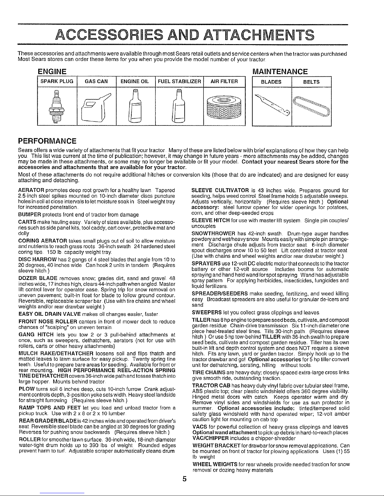
ENGINE MAINTENANCE
SPARK PLUG GAS CAN ENGINE OtL FUEL STABILIZER AIR FILTER BLADES BELTS
PERFORMANCE
Sears offers a wide variety of attachments that fit your tractor Many of these are listed below with brief explanations of how they can help
you This list was current at the time of publication; however, it may change in future years - more attachments may be added, changes
may be made in these attachments, or some may no longer be available or fit your model Contact your nearest Sears store for the
accessories and attachments that are available for your tractor.
Most of these attachments do not require additional hitches or conversion kits (those that do are indicated) and are designed for easy
attaching and detaching
AERATOR promotes deep root growth for a healthy lawn Tapered
2 5-inch steel spikes mounted on 10-inch diameter discs puncture
holes insoil atclose intervals to Ietmoisture soak in Steelweight tray
for increased penetration
BUMPER protects front end of tractor from damage
CARTS make hauling easy Variety of sizes available, plus accesso-
ries such as side panel kits, tool caddy, cart cover, protective mat and
dolly
CORING AERATOR takes small plugs out of soil to allow moisture
andnutrientstoreachgrassreots 36-inchswath 24 hardened steel
coring tips 150 Ib capacity weight tray
DISC HARROW has 2 gangs of 4 steel blades that angle from 10 to
20 degrees, 40 inches wide Can hook 2 units intandem (Requires
sleeve hitch )
DOZER BLADE removes snow; grades dirt, sand and gravel 48
inches wide, 17inches high, clears 44-inch path when angled Master
lift control lever for operator ease Spring trip for snow removal on
uneven pavement; built-in float for blade to follow ground contour.
Reversible, replaceable scraper bar (Use with tire chains and wheel
weights and/or rear drawber weight )
EASY OIL DRAIN VALVE makes oil changes easier, faster
FRONT NOSE ROLLER canters in front of mower deck to reduce
chances of "scalping" on uneven terrain
GANG HITCH lets you tow 2 or 3 pull-behlnd attachments at
once, such as sweepers, dethatchers, aerators (not for use with
rollers, carts or other heavy attachments)
MULCH RAKEUDETRATCHER loosens soil and flips thatch and
matted leaves to lawn surface for easy pickup Twenty spring tine
teeth Useful to prepare bare areas forseeding. Available for front or
rear mounting. HIGH PERFORMANCE REEL-ACTION SPRING
TINE DETHATCH ERcovers 36-inch wide path and tosses thatch into
large hopper Mounts behind tractor
PLOW turns soil 6 inches deep, cuts 10-inch furrow Crank adjust-
ment controls depth, 3-position yoke setswidth. Heavy steel landside
for straight furrowing (Requires sleeve hitch )
RAMP TOPS AND FEET let you load and unload traclor from a
pickup truck Use with 2 x 8 or 2 x 10 lumber
REAR GRADER BLADE is42 inches wide and operated from driver's
seat Reversible steel blade can be angled at 30 degrees for grading
Reverses for pushing snow backwards (Requires sleeve hitch )
ROLLER for smoother lawn surface 36dnch wide, 18-inch diameter
water-tight drum holds up to 390 Ibs of weight Rounded edges
prevent harm to turf Adjustable scraper automatically cleans drum
SLEEVE CULTIVATOR is 43 inches wide. Prepares ground for
seeding, helps weed control Steel frame holds 5adjustable sweeps.
Adjusts vertically, horizontally (Requires sleeve hitch) Optional
accessory: steel furrow opener for wider openings for potatoes,
corn, and other deep-seeded crops
SLEEVE HITCH for use with master lift system Single pin couples/
uncouples
SNOWTHROWER has 42-inch swath Drum-type auger handles
powdery and wet/heavy snow Mounts easily with simple pin arrange-
ment Discharge chute adjusts from tractor seat 6-inch diameter
spout discharges snow 10 to 50 feet Lift controlled at tractor seat
(Use with chains and wheel weights and/or rear drawbar weight )
SPRAYERS use 12-volt DCe]ectdc motor that connects to the tractor
battery or other 12-volt source Includes booms for automatic
spraying and hand held wand for spot spraying Wand has adjustable
spray pattern For applying herbicides, insecticides,fungicides and
liquid fertilizers
SPREADER/SEEDERS make seeding, fertilizing, and weed killing
easy Broadcast spreaders are also useful for granular de-icers and
sand
SWEEPERS let you collect grass clippings and leaves
TILLER has 8hp engine to prepare seed beds, cultivate, and compost
garden residue Chain-drive transmission Six 11-inch diameterone
piece heat-treated steel tines. Tills 30-inch path (Requires sleeve
hitch ) Or use 5 hp tow-behind TILLER with 36-inch swath to prepare
seed beds, cultivate end compost garden residue. Tiller has its own
built-in lift and depth control system and does NOT require a sleeve
hitch Fits any lawn, yard or garden tractor Simply hook up to the
tractor drawbar and go! Optional accessories for 5 hp tiller convert
unit for dethatching, aerating, hilling without tools
TIRE CHAINS are heavy duty; closely spaced extra-large cross links
give smooth ride, outstanding traction
TRACTOR CAB has heavy duty vinyl fabric over tubular steel frame,
ABS plastic top; clear plastic windshield offers 360 degree visibility
Hinged metal doors with catch Keeps operator warm and d_"
Remove vinyl sides and windshields for use as sen protector in
summer. Optional accessories include: tinted/tempered solid
safety glass windshield with hand operated wiper; t2-volt amber
caution light for mounting on cab top
VACS for powerful collection of heavy grass clippings and leaves
Optional wand attachment topick up debris in hard-to-reach places
VAClCHIPPER includes a chipper-shredder
WEIGHT BRACKET for drawbar for snow removal applications. Can
be mounted on front of tractor for plowing applications Uses (1) 55
Ib weight
WHEEL WEIGHTS for rearwheels provide needed traction for snow
removal or dozing heavy materials
5
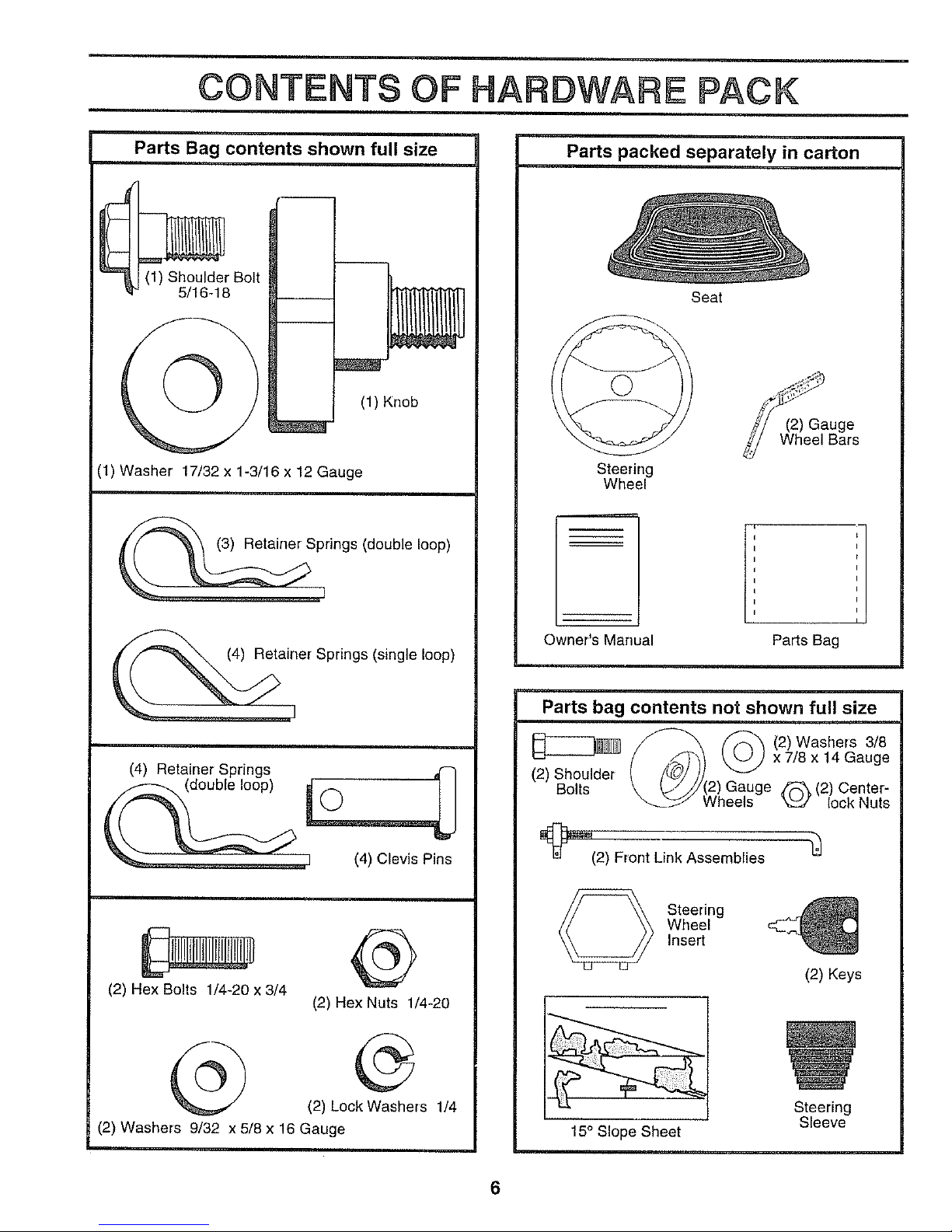
CONTENTS OF HARDWARE PACK
Parts Bag contents shown full size
(1) Shoulder Bolt
5/16-18
(1) Knob
(1) Washer 17/32 x 1-3/16 x 12 Gauge
Springs (double loop)
I
]er Springs (single loop)
(2) Hex Bolts 1/4-20 x 3/4
®
(2) Hex Nuts 1/4-20
(2) Lock Washers 1/4
(2) Washers 9/32 x 5/8 x 16 Gauge
Parts packed separately in carton
Steering
Wheel
Owner's Manual
Seat
(2) Gauge
Wheel Bars
t
I
I
I
I
I
I
I
I
Parts Bag
Parts bag contents not shown full size
(2) Shoulder
Bolts
Wheels
(2) Washers 3/8
x 7/8 x 14 Gauge
Q(2) Center-
lock Nuts
_(2) Front Link Assemblies "_
Steering
Wheel
Insert
(2) Keys
15° Slope Sheet
6
Steering
Sleeve
ASSEMBLY
Your new tractor has been assembled atthe factory with the exception of those parts left unassembled for shipping purposes.
To ensure safe and proper operation of your tractor all parts and hardware you assemble must be tightened securely Use
the correct tools as necessary to insure proper tightness
TOOLS REQUIRED FOR ASSEMBLY
A socket wrench set will make assembly easier. Standard
wrench sizes are listed.
(2) 7/16" wrenches Tire pressure gauge
(1) 1/2" wrench Utility knife
(1) 9/'16" wrench
(1) 3/4" socket with drive ratchet
When right or left hand is mentioned in this manual, it
means when you are in the operating position (seated
behind the steering wheel).
TO REMOVE TRACTOR FROM CARTON
UNPACK CARTON
o Remove al! accessible loose parts and parts cartons
from carton (See page 6).
• Cut, from top to bottom, along lines on all four corners
of carton, and lay panels flaL
° Check for any additional loose parts or cartons and
remove.
BEFORE ROLLING TRACTOR OFF SKiD
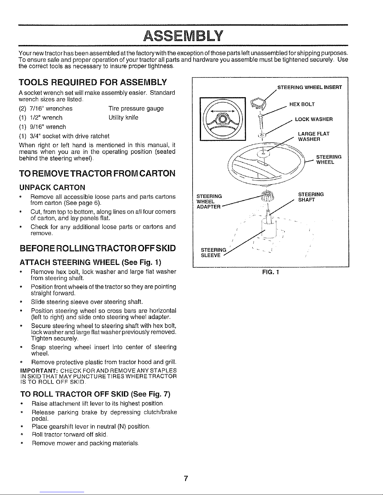
ATTACH STEERING WHEEL (See Fig. 1)
Remove hex bolt, lock washer and large flat washer
from steering shafL
Position front wheels of the tractor so they are pointing
straight forward.
Slide steering sleeve over steering shafL
o Position steering wheel so cross bars are horizontal
(left to right) and slide onto steering wheel adapter.
Secure steering wheel to steering shaft with hex bolt,
lock washer and large flat washer previously removed.
Tighten securely.
° Snap steering wheel insert into center of steering
wheel.
Remove protective plastic from tractor hood and grill,
IMPORTANT: CHECK FOR AND REMOVE ANY STAPLES
IN SKID THAT MAY PUNCTURE TIRES WHERE TRACTOR
IS TO ROLL OFF SKID
FIG. 1
TO ROLL TRACTOR OFF SKID (See Fig. 7)
Raise attachment lift lever to its highest position
o Release parking brake by depressing clutch/brake
pedal.
Place gearshift lever in neutral (N) position.
° Roll tractor forward off skid
Remove mower and packing materials
7
BLY
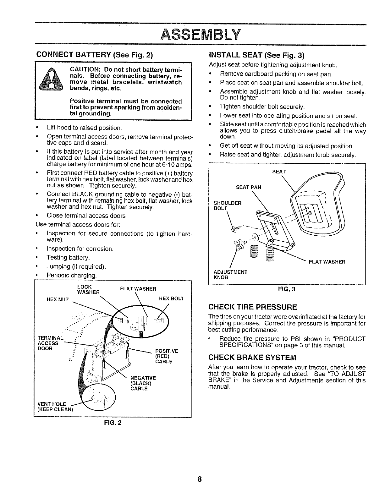
CONNECT BATTERY (See Fig. 2)
&
CAUTION: Do not short battery termi-
nals. Before connecting battery, re-
move metal bracelets, wristwatch
bands, rings, etc.
Positive terminal must be connected
first to prevent sparking from acciden-
tal grounding.
• Lift hood to raised position
• Open terminal access doors, remove terminal protec-
tive caps and discard.
• If this battery is put into service after month and year
indicated on label (label located between terminals)
charge battery for minimum of one hour at 6-10 amps
o First connect RED battery cable to positive (+) battery
terminal with hex bolt, flat washer, lock washer and hex
nut as shown Tighten securely
• Connect BLACK grounding cable to negative (-) bat-
tery terminal with remaining hex bolt, flat washer, lock
washer and hex nut Tighten securely
° Close terminal access doors
Use terminal access doors for:
Inspection for secure connections (to tighten hard-
ware)
= Inspection for corrosion
. Testing battery
° Jumping (if required).
Periodic charging.
LOCK FLAT WASHER
WASHER
HEX NUT HEXBOLT
TERMINAL ."'
ACCESS
DOOR .;
POSITIVE
(RED)
CABLE
NEGATIVE
(BLACK)
CABLE
VENT HOLE
KEEP CLEAN)
FIG. 2
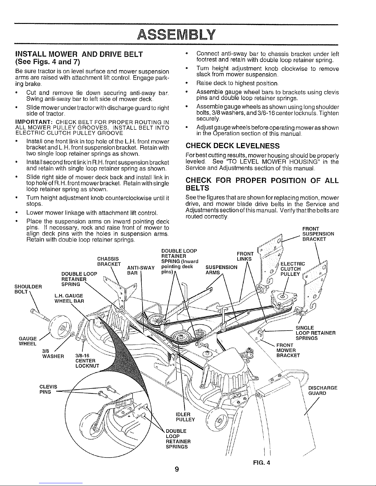
INSTALL SEAT (See Fig. 3)
Adjust seat before tightening adjustment knob_
° Remove cardboard packing on seat pan
• Place seat on seat pan and assemble shoulder boll
° Assemble adjustment knob and flat washer loosely
Do not tighten
° Tighten shoulder bolt securely
Lower seat into operating position and sit on seal
° Slide seat until a comfortable position is reached which
allows you to press clutch/brake pedal all the way
down
Get off seat without moving its adjusted position
• Raise seat and tighten adjustment knob securely_
SEAT
SEAT PAN
SHOULDER
BOLT
ADJUSTMENT
KNOB
FIG. 3
FLAT WASHER
CHECK TIRE PRESSURE
The tires on your tractor were overinflated at the factory for
shipping purposes_ Correct tire pressure is important for
best cutting performance
° Reduce tire pressure to PSI shown in "PRODUCT
SPECIFICATIONS" on page 3 of this manual
CHECK BRAKE SYSTEM
After you learn how to operate your tractor, check to see
that the brake is properly adjusted See "TO ADJUST
BRAKE" in the Service and Adjustments section of this
manual
8
ASSEMBLY
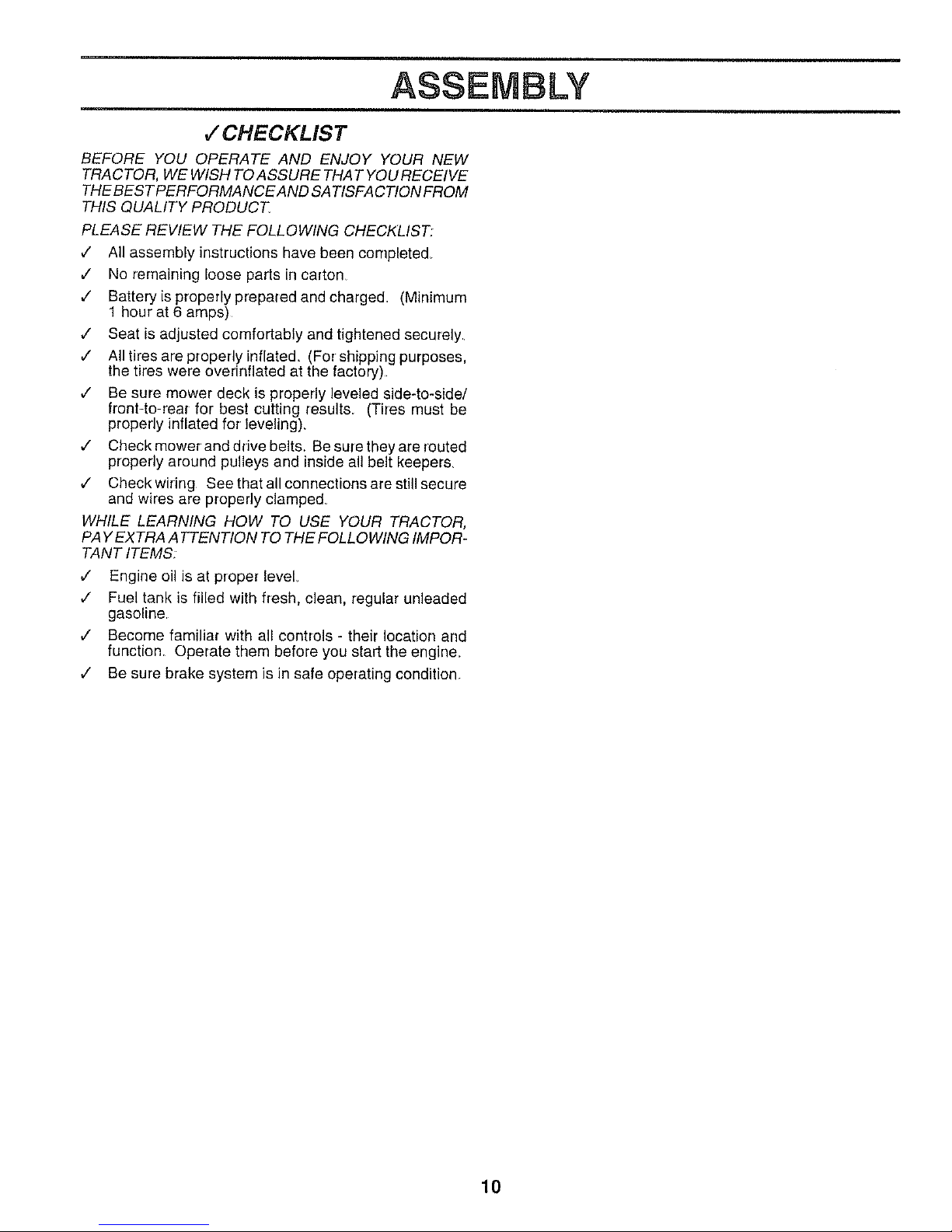
INSTALL MOWER AND DRIVE BELT
(See Figs. 4 and 7)
Be sure tractor is on level surface and mower suspension
arms are raised with attachment lift control. Engage park-
ing brake
o Cut and remove tie down securing anti-sway bar
Swing anti-sway bar to left side of mower deck
• Slide mower under tractor with discharge guard to right
side of tractor
IMPORTANT: CHECK BELT FOR PROPER ROUTING IN
ALL MOWER PULLEY GROOVES. INSTALL BELT INTO
ELECTRIC CLUTCH PULLEY GROOVE
Install one front link in top hole of the LH. front mower
bracket and L H front suspension bracket. Retain with
two single loop retainer springs as shown
Install second front link in RH front suspension bracket
and retain with single loop retainer spring as shown.
Slide right side of mower deck back and install link in
top hole of R H front mower bracket Retain with single
loop retainer spring as shown.
Turn height adjustment knob counterclockwise until it
stops
Lower mower linkage with attachment lift control
Place the suspension arms on inward pointing deck
pins. If necessary, rock and raise front of mower to
align deck pins with the holes in suspension arms
Retain with double loop retainer springs.
SHOULDER
CHASSIS
BRACKET
DOUBLE LOOP
RETAINER
SPRING _
L.H. GAUGE "
WHEEL BAR
ANTI-SWAY
BAR
Connect anti-sway bar to chassis bracke[ under left
footrest and retain with double loop retainer spring.
Turn height adjustment knob clockwise to remove
slack from mower suspension,
Raise deck to highest position
Assemble gauge wheel bars to brackets using clevis
pins and double loop retainer springs.
Assemble gauge wheels as shown using long shoulder
bolts, 3/8 washers, and 3/8-16 center Iocknuts Tighten
securely
Adjust gauge wheels before operating mower as shown
in the Operation section of this manual
CHECK DECK LEVELNESS
For best cutting results, mower housing should be properly
leveled See "TO LEVEL MOWER HOUSING" in the
Service and Adjustments section of this manual
CHECK FOR PROPER POSITION OF ALL
BELTS
See the figures that are shown for replacing motion, mower
drive, and mower blade drive belts in the Service and
Adjustments section ofthis manual. Verify that the belts are
routed correctly
FRONT
SUSPENSION
BRACKET
DOUBLE LOOP
RETAINER FRONT
SPRING (Inward LINKS
pointing deck SUSPENSION
pins) ARMS
GAUGE
WHEEL
3/8
WASHER
3/8-16
CENTER
LOCKNUT
SINGLE
LOOP RETAINER
SPRINGS
\,, MOWER
BRACKET
\.\
",\
CLEVIS
PINS
DISCHARGE
GUARD
IDLER
PULLEY
LOOP
RETAINER
SPRINGS
FIG. 4
9
ASSEMBLY
,/CHECKLIST
BEFORE YOU OPERATE AND ENJOY YOUR NEW
TRACTOR, WE WISH TO ASSURE THAT YOU RECEIVE
THEBES TPERFORMANCE AND SA TISFACTION FROM
THIS QUALITY PRODUCT,
PLEASE REVIEW THE FOLLOWING CHECKLIST,
¢" All assembly instructions have been completed
¢" No remaining loose parts in carton
¢" Batteryis properly prepared and charged (Minimum
1 hour at 6 amps)
¢ Seat is adjusted comfortably and tightened securely.
,/ All tires are properly inflated, (For shipping purposes,
the tires were overinflated at the factory).
,/ Be sure mower deck is properly leveled side-to-side/
front-to-rear for best cutting results_ (Tires must be
properly inflated for leveling),
¢ Check mower and drive belts, Be sure they are routed
properly around pulleys and inside all belt keepers,
v" CheckwMng See that all connections are still secure
and wires are properly clamped_
WHILE LEARNING HOW TO USE YOUR TRACTOR,
PAY EXTRA ATTENTION TO THE FOLLOWING IMPOR-
TANT ITEMS:
v" Engine oil is at proper level
,/' Fuel tank is filled with fresh, clean, regular unleaded
gasoline
,/ Become familiar with all controls - their location and
function Operate them before you start the engine_
,/ Be sure brake system is in safe operating condition
10
OPERATmON
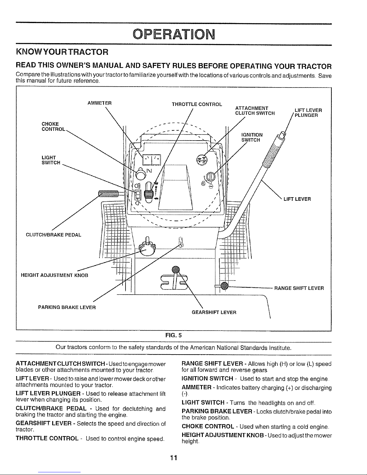
KNOWYOURTRACTOR
READ THIS OWNER'S MANUAL AND SAFETY RULES BEFORE OPERATING YOUR TRACTOR
Compare the illustrations with your tractor to familiarize yourself with the locations of various controls and adjustments Save
this manual for future reference,
AMMETER
CHOKE
SWITCH
THRO_LECONTROL
ATTACHMENT LIFT LEVER
CLUTCH SWITCH
LIFT LEVER
CLUTCH/BRAKE PEDAL
HEIGHT ADJUSTMENT KNOB
PARKING BRAKE LEVER
\
GEARSHIFT LEVER
RANGE SHIFT LEVER
FIG. 5
Our tractors conform to the safety standards of the American National Standards Institute.
ATTACHMENT CLUTCH SWITCH - Used toengage mower
blades or other attachments mounted to your tractor
LIFT LEVER- Used to raise and lower mower deck or other
attachments mounted to your tractor,
LIFT LEVER PLUNGER - Used to release attachment lift
lever when changing its position.
CLUTCH/BRAKE PEDAL - Used for declutching and
braking the tractor and starting the engine.
GEARSHIFT LEVER - SeFectsthe speed and direction of
tractor,
THROTTLE CONTROL - Used to control engine speed_
RANGE SHIFT LEVER - Allows high (H) or low (L) speed
for all forward and reverse gears
IGNITION SWITCH - Used to start and stop the engine
AMMETER - Indicates battery charging (+) or discharging
(-)
LIGHT SWITCH - Turns the headlights on and off.
PARKING BRAKE LEVER - Locks clutch/brake pedal into
the brake position,
CHOKE CONTROL - Used when starting a cold engine_
HEIGHTADJUSTMENT KNOB- Usedto adjustthe mower
height,
11
OPERATION
The operation of any tractor can result in foreign objects thrown into the eyes, which carl result
nnsevere eye damage. Always wear safety glasses or eye shields while operating your tractor
or performing any adjustments or repairs, We recommend a wide vision safety mask over the
spectacles or standard safety glasses.
HOW TO USE YOUR TRACTOR
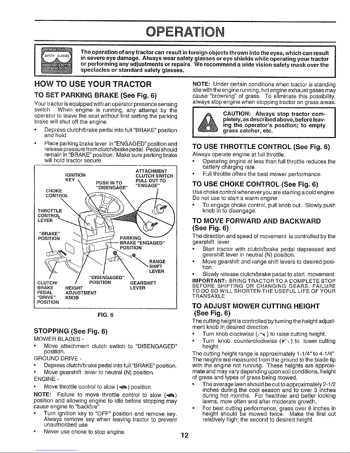
TO SET PARKING BRAKE (See Fig. 6)
Your tractor is equipped with an operator' presence sensing
switch When engine is running, any attempt by the
operator to leave the seat without first setting the parking
brake will shut off the eng!ne
= Depress clutch/brake pedal into full "BRAKE" position
and hokf
NOTE: Under certain conditions when tractor is standing
idlewith the eng!ne running, hot engine exhaust gases may
cause "browning" of grass. To eliminate this possibility,
always stop engine when stopping tractor on grass areas,
pletely, as described above, before leav-
ing the operator's position; to empty
grass catcher', etc.
Place parking brake lever in "ENGAGED" position and
release pressure from clutch/brake pedal Pedal should
remain in "BRAKE" position Make sure parking brake
will hold tractor secure
ATTACHMENT
IGNITION CLUTCH SWITCH
KEY PUSHINTO PULL OUTTO
"DISENGAGE" "ENGAGE"
CHOKE
CONTROL
THROTTLE
CONTROL
LEVER
"BRAKE"
POSITION
RANGE
SHIFT
LEVER
"DISENGAGED"
CLUTCH/ POSITION GEARSHIFT
BRAKE HEIGHT LEVER
PEDAL ADJUSTMENT
"DRIVE" KNOB
POSITION
FIG. 6
STOPPING (See Fig. 6)
MOWER BLADES -
Move attachment clutch switch to "DISENGAGED"
position_
GROUND DRIVE -
° Depress clutch/brake pedal into full "BRAKE" position
• Move gearshift lever to neutral (N) position
ENGINE -
o _/Iove throttle control to slow (-_) position,
NOTE: Failure to move throttle control to slow (,_)
position and allowing engine to idle before stopping may
cause engine to "backfire"
Turn ignition key to "OFF" position and remove key.
Always remove key when leaving tractor to prevent
unauthorized use
• Never use choke to stop engine
TO USE THROTTLE CONTROL (See Fig. 6)
Always operate engine at full throttle
• Operating engine at less than full throttle reduces the
battery charging rate
o Full throttle offers the best mower performance.
TO USE CHOKE CONTROL (See Fig. 6)
Use choke control whenever you are starting a cold engine,
Do not use to start a warm engine
• To engage choke control, pull knob out Slowly push
knob in to disengage_
TO MOVE FORWARD AND BACKWARD
(See Fig. 6)
The direction and speed of movement is controlled by the
gearshift lever
Start tractor with clutch/brake peda! depressed and
gearshift lever in neutral (N) position_
• Move gearshift and range shift levers to desired posi-
tion,
Slowly release clutch/brake pedal to start movemenL
IMPORTANT: BRING TRACTOR TO A COMPLETE STOP
BEFORE SHIFTING OR CHANGING GEARS. FAILURE
TO DO SOWILL SHORTEN THE USEFUL LIFE OF YOUR
TRANSAXLE
TO ADJUST MOWER CUTTING HEIGHT
(See Fig. 6)
The cutting height is controlled byturning the height adjust-
ment knob in desired direction
Turn knob clockwise (t_,_) to raise cutting height
= Turn knob counterclockwise (_) to lower cutting
height.
The cutting height range is approximately 1-1/4" to 4-1/4"
The heights are measured from the ground to the blade tip
with the engine not running. These heights are approxi-
mate and may vary depending upon soil conditions, height
of grass and types of grass being mowed_
• The average lawn should be cut to approximately 2-1/2
inches during the cool season and to over 3 inches
during hot months. For healthier and better looking
lawns, mew often and after moderate growth.
° For best cutting performance, grass over 6 inches in
height should be mowed twice_ Make the first cut
relatively high; the second to desired height,
12
OPERATION
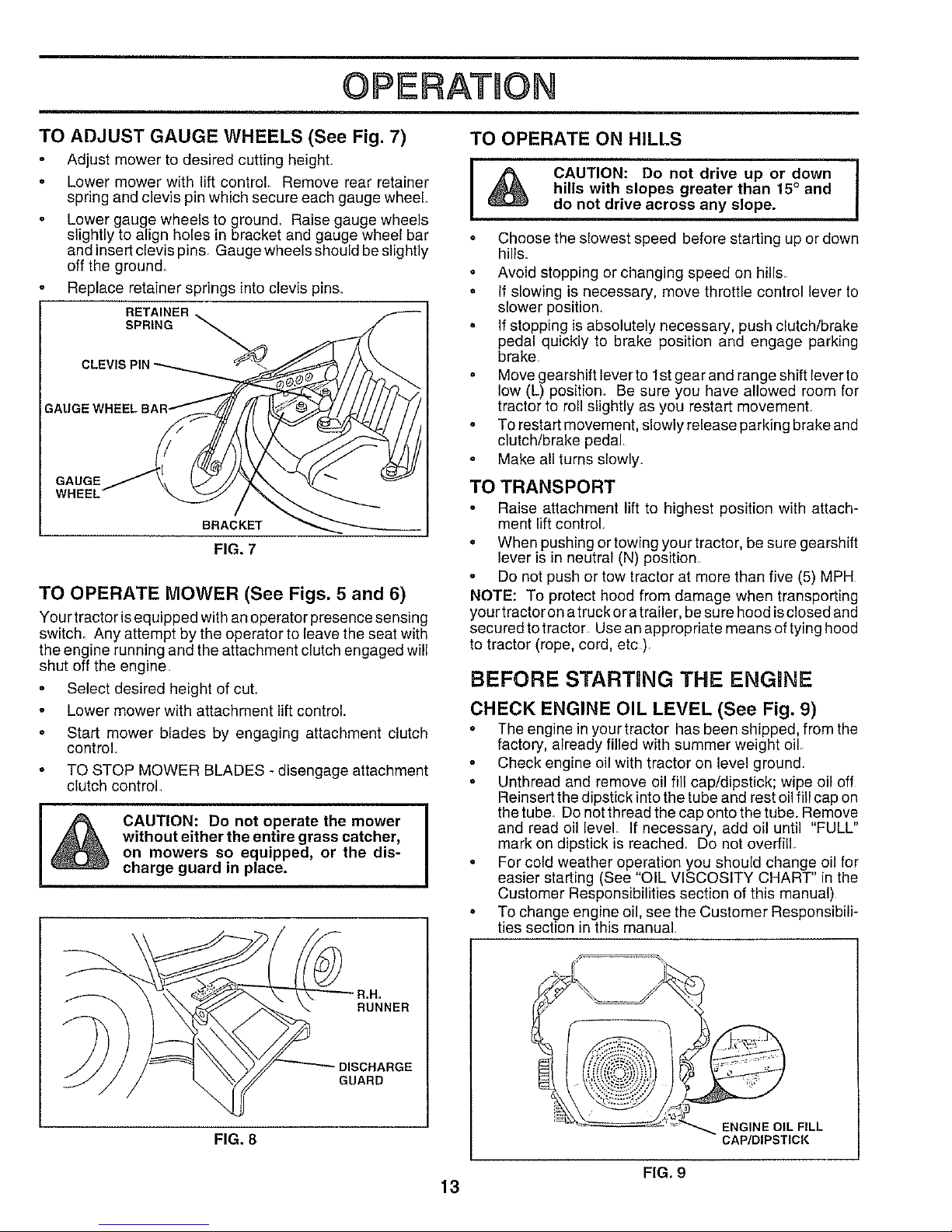
TO OPERATE ON HILLSTO ADJUST GAUGE WHEELS (See Fig. 7)
Adjust mower to desired cutting height
• Lower mower with lift control Remove rear retainer
spring and clevis pin which secure each gauge wheel
Lower gauge wheels to ground_ Raise gauge wheels
slightly to align holes in bracket and gauge wheel bar
and insert clevis pins. Gauge wheels should beslightly
off the ground.
Replace retainer springs into clevis pins.
RETAINER
SPRING _
GAUGE
WHEEL
BRACKET
FIG. 7
TO OPERATE MOWER (See Figs. 5 and 6)
Your tractor isequipped with anoperator presence sensing
switch. Any attempt by the operator to leave the seat with
the engine running and the attachment clutch engaged will
shut off the engine.
Select desired height of cuL
Lower mower with attachment lift control.
Start mower blades by engaging attachment clutch
control
TO STOP MOWER BLADES -disengage attachment
clutch control
I
CAUTION: Do not operate the mower
without either the entire grass catcher,
I
on mowers so equipped, or the dis-
charge guard in place.
RUNNER
DISCHARGE
GUARD
FIG. 8
I _ CAUTION: Do not drive up or down
hills with slopes greater than 15° and
do not drive across any slope.
Choose the slowest speed before starting up or down
hills.
Avoid stopping or changing speed on hills
. If slowing is necessary, move throttle control lever to
slower position.
• If stopping is absolutely necessary, push clutch/brake
pedal quickly to brake position and engage parking
brake
Move gearshift lever to 1st gear and range shift lever to
low (L) position. Be sure you have allowed room for
tractor to roll slightly as you restart movement
• To restart movement, slowly release parking brake and
clutch/brake pedal
Make all turns slowly.
TO TRANSPORT
° Raise attachment lift to highest position with attach-
ment lift control
• When pushing or towing your tractor, be sure gearshift
lever is in neutral (N) position
Do not push or tow tractor at more than five (5) MPH
NOTE: To protect hood from damage when transporting
your tractor on atruck or a trailer, be sure hood isclosed and
secured to tractor Use an appropriate means of tying hood
to tractor (rope, cord, etc).
BEFORE STARTING THE ENGINE
CHECK ENGINE OIL LEVEL (See Fig. 9)
• The engine in your tractor has been shipped, from the
factory, already filled with summer weight oil
Check engine oil with tractor on level ground.
Unthread and remove oil fill cap/dipstick; wipe oil off
Reinsert the dipstick into the tube and rest oil fill cap on
the tube. Do not thread the cap onto the tube. Remove
and read oil level If necessary, add oil until "FULL"
mark on dipstick is reached. Do not overfill
° For cold weather operation you should change oil for
easier starting (See "OIL VISCOSITY CHART" in the
Customer Responsibilities section of this manual)
° To change engine oil, see the Customer Responsibili-
ties section in this manual.
ENGINE OIL FILL
CAP/DIPSTICK
FIG. 9
13
OIPERAT ON
ADD GASOLINE IVlOWING TiPS
Fill fuel tank Use fresh, clean, regular unleaded
gasoline (Use of leaded gasoline will increase carbon
and lead oxide deposits and reduce valve life)
IMPORTANT: WHEN OPERATING IN TEMPERATURES
BELOW 32°F(0°C), USE FRESH, CLEAN WINTER G RADE
GASOLINE TO HELP INSURE GOOD COLD WEATHER
STARTING
WARNING: Experience indicates that alcohol blended
fuels (called gasohol or using ethanol or methanol) can
attract moisture which leads to separation and formation of
acids during storage Acidic gas can damage the fuel
system of an engine while in storage. To avoid engine
problems, the fuel system should be emptied before stor-
age of 30 days or longer. Drain the gas tank, start the
engine and let it run until the fuel lines and carburetor are
empty, Use fresh fuel next season. See Storage Instruc-
tions for additional information_ Never use engine or
carburetor cleaner products in the fuel tank or permanent
damage may occur,
CAUTION: Fill to bottom of gas tank
filler neck. Do not overfill. Wipe off any
spilled oil or fuel, Do not store, spill or
use gasoline near an open flame,
TO START ENGINE (See Fig. 6)
When starting engine for the first time or if engine has run
out of fuel, it will take extra cranking time to move fuel from
the tank to the engine
Depress clutch/brake pedal and set parking brake.
Place gearshift lever in neutral (N) position,
° Move attachment clutch to "DISENGAGED" position
Pull choke control out to choke (N) position for cold
engine start, For' warm engine start do not use choke
control.
o Move throttle control to midway between fast ('_) and
slow (,,_.) positions.
Insert key into ignition and tum key clockwise to"START"
position and release key as soon as engine starts. Do
not run starter continuously for more than fifteen
seconds per minute. If engine does not start after
several attempts, move throttle control to fast (,_)
position, wait a few minutes and try again_
When engine starts, slowly push choke control in_
Move throttle control to fast ('_) position.
Allow engine to warm up for a few minutes before
engaging drive or attachments
NOTE: If at a high altitude (above 3000 feet) or in cold
temperatures (below 32°F), the carburetor fuel mixture
may need to be adjusted for best engine performance See
"TO ADJUST CARBURETOR" in the Service and Adjust-
ments section of this manual
Tire chains cannot be used when the mower housing is
attached to tractor.
o Mower should be properly leveled for best mowing
performance. See "TO LEVEL MOWER HOUSING" in
the Service and Adjustments section of this manual
° Use the runner on the right hand side of mower as a
guide The blade cuts approximately an inch outside
the runner (See Fig 8),
o The left hand side of mower should be used for trim-
ming.
° Drive so that clippings are discharged onto the area
that has been cut. Have the cut area to the right of the
machine. This will result in a more even distribution of
clippings and more uniform cutting
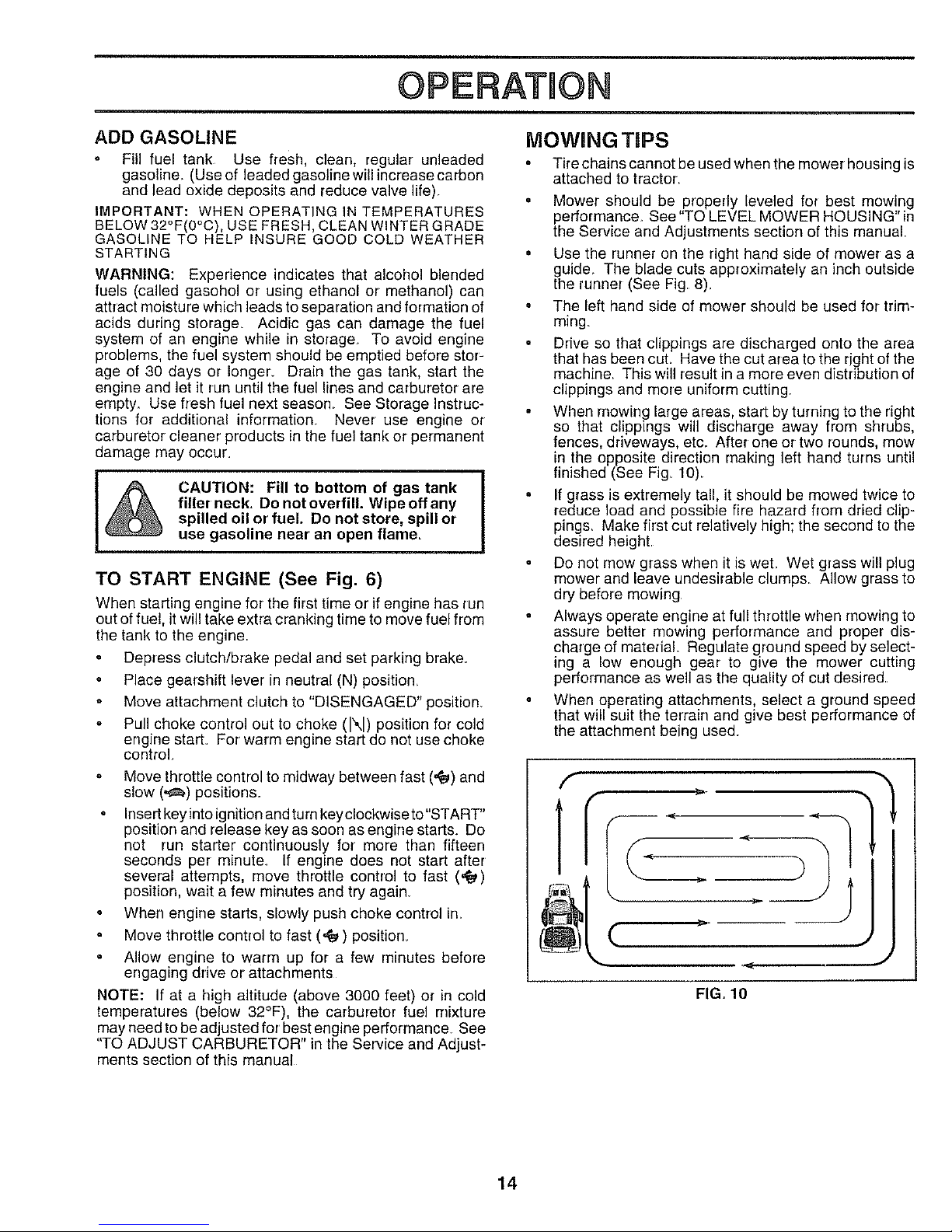
When mowing large areas, start by turning to the right
so that clippings will discharge away from shrubs,
fences, driveways, etc. After one or two rounds, mow
in the opposite direction making left hand turns until
finished (See Fig, 10)_
• If grass is extremely tall, it should be mowed twice to
reduce load and possible fire hazard from dried clip-
pings, Make first cut relatively high; the second to the
desired height
Do not mow grass when it is weL Wet grass will plug
mower and leave undesirable clumps Allow grass to
dry before mowing
Always operate engine at full throttle when mowing to
assure better mowing performance and proper dis-
charge of material Regulate ground speed by select-
ing a low enough gear to give the mower cutting
performance as well as the quality of cut desired.
When operating attachments, select a ground speed
that will suit the terrain and give best performance of
the attachment being used.
U
_.. _< J
FIG. 10
14
CUSTOMER RESPONSUB_LnTmES
FILL,NDATES _'_°_ _._"__Z_J__I_o_
ABYREGOLAROUCOSERV,CEMPLETB ! .,_O__..X__ _,y,_ __" "_d_¢-_:_ _V'OEOA-_S
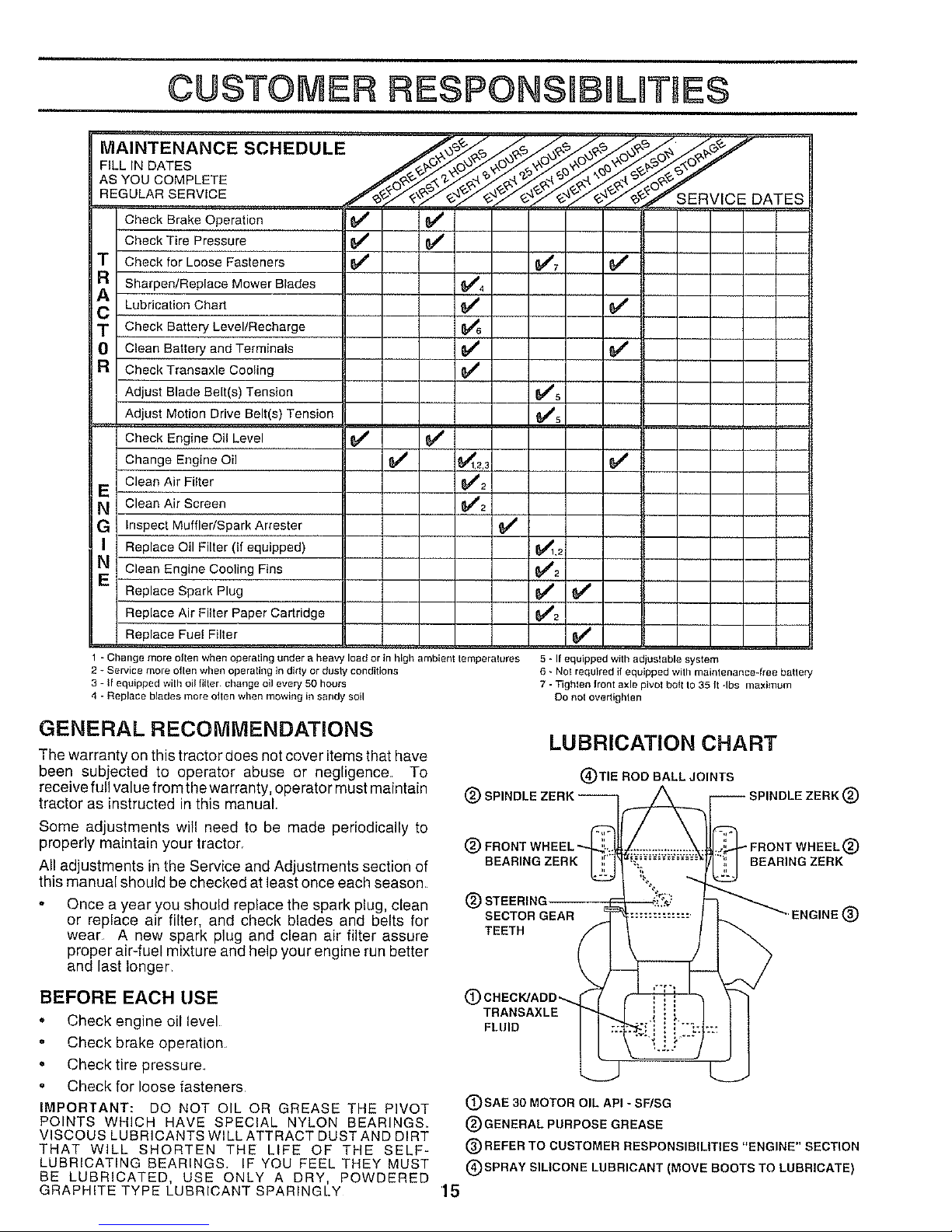
Check Brake Operation 1_ {/
CheckTire Pressure 6/' 6/
T Check for LooseFasteners _' _7
a Sharpen/Replace Mower Blades _4
A LubricationChart _ 6##'
T Check Battery Level/Recharge
0 Clean Batteryand Terminals _ 6#"'
a CheckTransaxle Cooling
Adjust Blade Belt(s) Tension _5
Adjust Motion DriveBelt(s)Tension (_s
CheckEngine Oil Level 6#`#
ChangeEngineOil $/ _t2.3 6/
CleanAir Filter _2
E
N CleanAir Screen 64#2
G Inspect Muffler/Spark Arrester
Replace Oil Filter (If equipped) _,2
NE Clean Engine Cooling Fins _2
Replace Spark Plug 6/ 6/'
ReplaceAir Filter PaperCartridge 6##2
Replace Fue!Filter 6_
1 - Change more olten when operating under a heavy load or in high ambienl temperatures
2 _ Service more otten when operating in dirty or dusly conditions
3 - If equipped wilh oil filter change ell every 50 hours
4 - Replace blades more olten when mowing in sandy soil
5 • If equipped with adjustable system
6 - Nol required if equipped with mainlenance-lree batlery
7 - Tighlen front axle pivot bo_tto 35 It qbs maximum
DO not ovedighlen
GENERAL RECOMMENDATIONS
The warranty on this tractor does net cover items that have
been subjected to operator abuse or negligence. To
receive full value from the warranty, operator must maintain
tractor as instructed in this manual.
Some adjustments will need to be made periodically to
properly maintain your tractor,
All adjustments in the Service and Adjustments section of
this manual should be checked at least once each season
Once a year you should replace the spark plug, clean
or replace air filter, and check blades and belts for
wear A new spark plug and clean air filter assure
proper air-fuel mixture and help your engine run better
and last longer
BEFORE EACH USE
" Check engine oil level
, Check brake operation
• Check tire pressure
" Check for loose fasteners
IMPORTANT: DO NOT OIL OR GREASE THE PIVOT
POINTS WHICH HAVE SPECIAL NYLON BEARINGS,
VISCOUS LUBRICANTS WILL ATTRACT DUST AND DIRT
THAT WILL SHORTEN THE LIFE OF THE SELF-
LUBRICATING BEARINGS. IF YOU FEEL THEY MUST
BE LUBRICATED, USE ONLY A DRY, POWDERED
GRAPHITE TYPE LUBRICANT SPARINGLY
®
LUBRICATION CHART
(_)TIE ROD BALL JOINTS
klDLE ZERK ®
® - FRONT WHEEL (_)
BEARING ZERK BEARING ZERK
® STEERING,
SECTOR GEAR ENGINE (_
TEETH
(D CHECK/ADD--.
TRANSAXLE
FLUID
(DSAE 30 MOTOR OIL API - SF/SG
®GENERAL PURPOSE GREASE
®REFER TO CUSTOMER RESPONSIBILITIES "ENGINE" SECTION
®SPRAY SILICONE LUBRICANT (MOVE BOOTS TO LUBRICATE)
'15
CUSTOMER RESlPONSIB L TIES
TRACTOR
Always observe safety rules when performing any rrrainte-
nance.
BRAKE OPERATION
If tractor requires more than six (6) feet stopping distance
at high speed in highest gear, then brake must be adjusted.
(See "TO ADJUST BRAKE" in the Service and Adjust-
ments section of this manual)_
TIRES
Maintain proper air pressure in all tires (See "PROD-
UCT SPECIFICATIONS" on page 3 of this manual)
Keep tires free of gasoline, oil, or insect control chemi-
cals which can harm rubber
o Avoid stumps, stones, deep ruts, sharp objects and
other hazards that may cause tire damage
BLADE CARE
For best results mower blades must be kept sharp, Re-
place bent or damaged blades
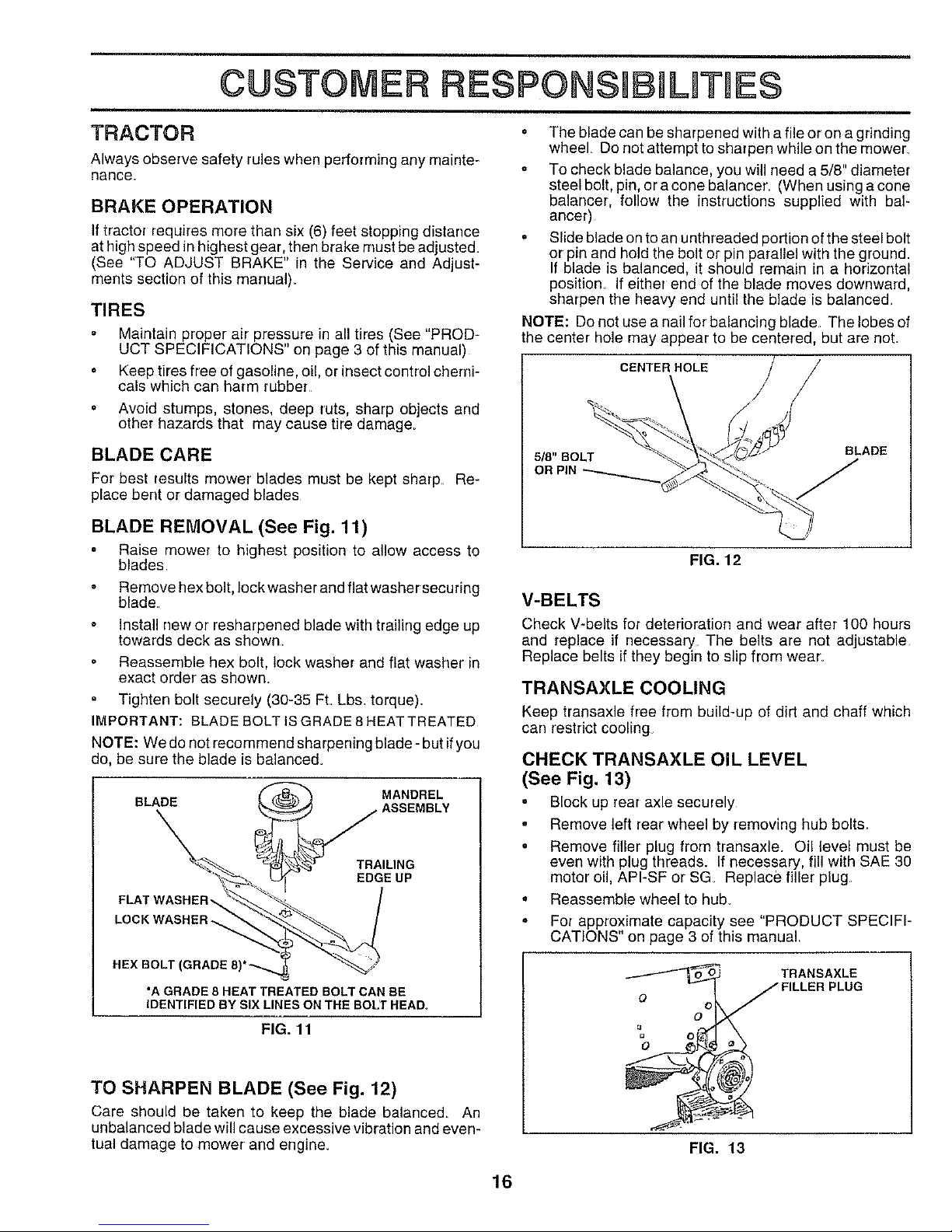
BLADE REMOVAL (See Fig. 11)
o Raise mower to highest position to allow access to
blades
Remove hex bolt, lock washer and flat washer securing
blade
Install new or resharpened blade with trailing edge up
towards deck as shown.
Reassemble hex bolt, lock washer and flat washer in
exact order as shown.
Tighten bolt securely (30-35 FL Lbs torque).
IMPORTANT: BLADE BOLT ISGRADE 8 HEAT TREATED
NOTE: We do not recommend sharpening blade- but if you
do, be sure the blade is balance&
BLADE
MANDREL
TRAILING
EDGE UP
LOCK WASHER_
HEX BOLT
*A GRADE 8 HEAT TREATED BOLT CAN BE
IDENTIFIED BY SIX LINES ON THE BOLT HEAD,
FIG. 11
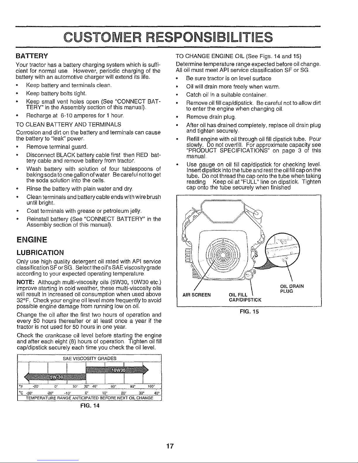
TO SHARPEN BLADE (See Fig. 12)
care should be taken to keep the blade balance& An
unbalanced blade will cause excessive vibration and even-
tual damage to mower and engine.
o The blade can be sharpened with a file or on a grinding
wheel Do not attempt to sharpen while on the mower
o To check blade balance, you will need a 5/8" diameter
steel bolt, pin, or a cone balancer. (When using a cone
balancer, follow the instructions supplied with bal-
ancer)
= Slide blade on to an unthreaded portion of the steel bolt
or pin and hold the bolt or pin parallel with the ground.
If blade is balanced, it should remain in a horizontal
position If either end of the blade moves downward,
sharpen the heavy end until the blade is balanced.
NOTE: Do not use a nail for' balancing blade The lobes of
the center hole may appear to be centered, but are not.
CENTER HOLE
5/8" BOLT BLADE
OR PIN
FIG. 12
V-BELTS
Check V-belts for deterioration and wear after 100 hours
and replace if necessary. The belts are not adjustable
Replace belts if they begin to slip from wear_
TRANSAXLE COOLING
Keep transaxle free from build-up of dirt and chaff which
can restrict cooling
CHECK TRANSAXLE OIL LEVEL
(See Fig. 13)
o Block up rear axle securely
Remove left rear wheel by removing hub bolts.
• Remove filler plug from transaxle. Oil level must be
even with plug threads. If necessary, fill with SAE 30
motor oil, API-SF or SG Replace filler plug.
° Reassemble wheel to hub.
• For approximate capacity see "PRODUCT SPECIFI-
CATIONS" on page 3 of this manual.
o
o °
TRANSAXLE
J FILLER PLUG
i
FIG. 13
16
CUSTOMER RESPONSIB L TmES
,
BATTERY
Your tractor has a battery charging system which is suffi-
cient for normal use However. periodic charging of the
battery with an automotive charger will extend its life.
Keep battery and terminals clean
Keep battery bolts tight
o Keep small vent holes open (See "CONNECT BAT-
TERY" in the Assembly section of this manual)
° Recharge at 6-10 amperes for 1 hour
TO CLEAN BATTERY AND TERMINALS
Corrosion and dirt on the battery and terminals can cause
the battery to "leak" power
Remove terminal guard,
. Disconnect BLACK battery cable first then RED bat-
tery cable and remove battery from tractor
Wash battery with solution of four tablespoons of
baking soda to one gallon of water Be careful notto get
the soda solution into the cells,
o Rinse the battery with plain water and dry.
Clean terminals and battery cable ends with wire brush
until brighL
Coat terminals with grease or petroleum jelly_
° Reinstall battery (See "CONNECT BATTERY" in the
Assembly section of this manuel)
ENGINE
LUBRICATION
Only use high quality detergent ell rated with API service
classification SFor SG. Select the oil's SAE viscosity grade
according to your expected operating temperature
NOTE: Although multi-viscosity oils (5W30. 10W30 etc,)
improve starting in cold weather, these multi-viscosity oils
will result in increased oil consumption when used above
32°F. Check your engine oil level mere frequently to avoid
possible engine damage from running low on oil
Change the oil after the first two hours of operation and
every 50 hours thereafter or at least once a year if the
tractor is not used for 50 hours in one year.
Check the crankcase oil level before starting the engine
and after each eight (8) hours of operation, Tighten oil fill
cap/dipstick securely each time you check the oil level,
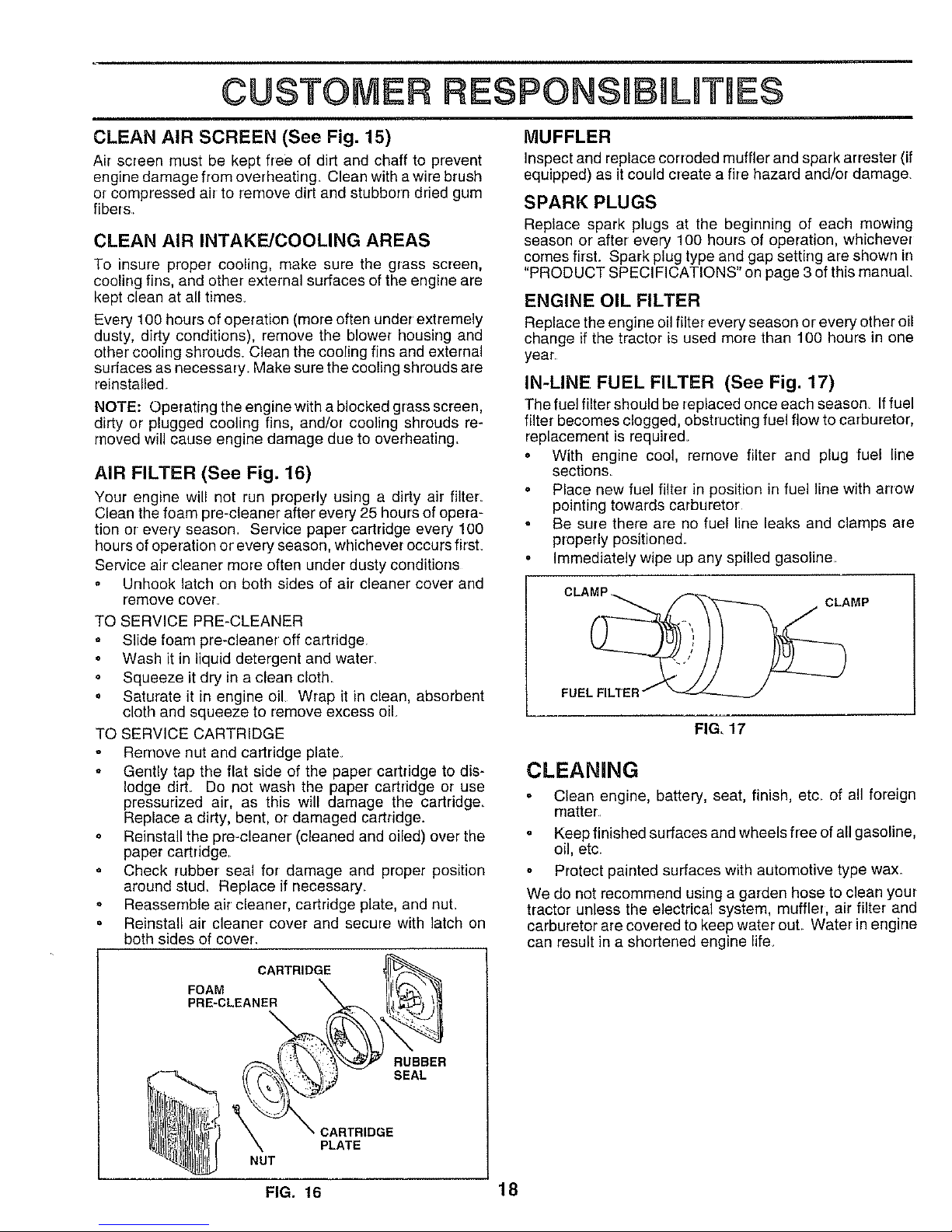
TO CHANGE ENGINE OIL (See Fig& 14 and 15)
Determine temperature range expected before oil change,
All oil must meet API service classification SF or SG
Be sure tractor is on level surface
Oil will drain more freely when warm,
° Catch oil in a suitable container
Remove oil fill cap/dipstick Be careful not to allow dirt
to enter the engine when changing oil,
Remove drain plug
After oi! has drained completely, replace oil drain plug
and tighten securely,
Refill engine with oil through oil fill dipstick tube. Pour
slowly. Do not overfill, For approximate capacity see
"PRODUCT SPECIFICATIONS" on page 3 of this
manual
Use gauge on oil fill cap/dipstick for checking level
Insert dipstick into the tube and rest the oil fill cap on the
tube. Do not thread the cap onto the tube when taking
reading Keep oil at"FULL" line on dipstick. Tighten
cap onto the tube securely when finished
AIR SCREEN
OIL DRAIN
PLUG
OIL FILL
CAP/DIPSTICK
FIG,, 15
SAE VISCOSITY GRADES
.20 _ 0 _ 30 _ 32 '_ 40 _ 600 GO=
_30_ .20 ° .10 _ 0 _' 10_ 20 _ 30 _ 40 _
TEMPERATURE RANGE ANTICIPATED BEFORE NEXT OiL CHANGE
FIG. 14
'17
CUSTOM RESPONSmBMLmTHES
CLEAN AIR SCREEN (See Fig. 15)
Air screen must be kept free of dirt and chaff to prevent
engine damage from overheating Clean with a wire brush
or compressed air to remove dirt and stubborn dried gum
fibers.
CLEAN AIR INTAKE/COOLING AREAS
To insure proper cooling, make sure the grass screen,
cooling fins, and other external surfaces of the engine are
kept clean at all time&
Every 100 hours of operation (more often under extremely
dusty, dirty conditions), remove the blower housing and
other cooling shrouds. Clean the cooling fins and external
surfaces as necessary. Make sure the cooling shrouds are
reinstalled
NOTE: Operating the engine with a blocked grass screen,
dirty or plugged cooling fins, and/or cooling shrouds re-
moved will cause engine damage due to overheating.
AIR FILTER (See Fig. 16)
Your engine will not run properly using a dirty air filter.
Clean the foam pre-cleaner after every 25 hours of opera-
tion or every season Service paper cartridge every 100
hours of operation or every season, whichever occurs firsL
Service air cleaner more often under dusty conditions
. Unhook latch on both sides of air cleaner cover and
remove cover_
TO SERVICE PRE-CLEANER
Slide foam pre-cleaner off cartridge
Wash it in liquid detergent and water_
Squeeze it dry in a clean cloth
. Saturate it in engine oil Wrap it in clean, absorbent
cloth and squeeze to remove excess oil
TO SERVICE CARTRIDGE
Remove nut and cartridge plate.
= Gently tap the flat side of the paper cartridge to dis-
lodge dirt, Do not wash the paper cartridge or use
pressurized air, as this will damage the cartridge,
Replace a dirty, bent, or damaged cartridge.
o Reinstall the pre-cleaner (cleaned and oiled) over the
paper cartridge,
o Check rubber seal for damage and proper position
around stu& Replace if necessary.
Reassemble air cleaner, cartridge plate, and nuL
= Reinstall air cleaner cover and secure with latch on
both sides of cover.
MUFFLER
Inspect and replace corroded muffler and spark arrester (if
equipped) as it could create afire hazard and/or damage,
SPARKPLUGS
Replace spark plugs at the beginning of each mowing
season or after every 100 hours of operation, whichever
comes first. Spark plug type and gap setting are shown in
"PRODUCT SPECIFICATIONS" on page 3 of this manual.
ENGINE OIL FILTER
Replace the engine oil filter every season or every other oil
change if the tractor is used more than 100 hours in one
year
IN-LINE FUEL FILTER (See Fig. 17)
The fuel filter should be replaced once each season If fuel
filter becomes clogged, obstructing rue! flow to carburetor,
replacement is require&
• With engine cool, remove filter and plug fuel line
sections
° Place new fuel filter in position in fuel line with arrow
pointing towards carburetor
° Be sure there are no fuel line leaks and clamps are
properly positioned.
° Immediately wipe up any spilled gasoline.
CLAM___ _'_k"-'_ CLAMP
FUE
FIG, 17
CLEANING
° Clean engine, battery, seat, finish, etc_ of all foreign
matter
Keep finished surfaces and wheels free of all gasoline,
oil, etc.
Protect painted surfaces with automotive type wax.
We do not recommend using a garden hose to clean your
tractor unless the electrical system, muffler, air filter and
carburetor are covered to keep water out Water in engine
can result in a shortened engine life.
FIG. 16 18
 Loading...