

Page 1
Operator's Manual
I;RFIFTSMRrl
AWN TRACTOR
21.0 HP,*42" Mower
Electric Start
6 Speed Transaxle
Model No.
917.25022
• EspaSol, p. 31
This product has a low emission engine which operates i
differently from previously built Before start the
engine, read and understand this Operator's Manual.
IMPORTANT: Foranswersto your questions
Read and follow all Safety about thisproduct,Call:
Rules and Instructions before 1-800-659-5917
operating this equipment. 5 am - 5 pm, Mon- Sat
Gasoline containing upto 10% ethanol (EIO) is acceptable for use in this machine. The
use of any gasoline exceeding 10% ethanol (El0) will void the product warranty.
Esta mdquina puede utilizar gasolina con un contenido de hasta el 10% de etano! (El0). El
uso de una gasolina que supere el 10% de etanol (EIO) anular_ la garantia del producto.
Sears Brands Management Corporation, Hoffman Estates, IL 60179 U.S.A.
Visit our Craftsman website:www.sears,comicraftsman *As rated bytheenginemanufacturer
engines.
Sears Craftsman Help Line
you
581865949 Rev. 2
I
Page 2
Warranty .................................................. 2
Safety Rules ............................................ 3
Product Specificat{ons ............................. 6
Assembly/Pre-Operation ......................... 7
Operation ................................................. 9
Maintenance .......................................... 15
Craftsman Riding Equipment Warranty
CRAFTSMAN FULL WARRANTY
FOR TWO YEARS from the date of purchase,all nan-expendable partsofthisridingequipmentare
warranted against any defects in material or workmanship, A defective non-expendable part will
receive free in-home repair or replacement if repairis impossible.
FOR FIVE YEARS from the date of purchase, the frame and front axle of this riding equipment are
warranted against any defects in material or workmanship.A defectiveframe orfront axlewiI1receive
free in-home repair or replacement if repair is impossible.
FOR 90 DAYS from the date of purchase, the battery (an expendable part) of this riding equipment
is warranted against any defects in material or workmanship (our testing proves that it will not hold a
charge). A defective battery will receive free in-home replacement•
ADDITIONAL LIFETIME LIMITED WARRANTY on CAST IRON FRONT AXLE (if equipped)
FOR AS LONG AS IT IS USED by the original owner afterthe fifthyear from the date of purchase, the
cast ironfront axle (if equipped) of this riding equipment iswarranted against any defects in matedaI or
workmanship. With proof of purchase, adefective cast front axle will receive free in-homereplacement.
WARRANTY SERVICE
For warranty coverage details to obtainfree repair or replacement, calI 1-800-659-5917 or visit the
web site',www.craftsman.com
In all cases above, if part repair or replacement is impossible,the riding equipment will be replaced
free of charge with the same or an equivalent model.
All of the above warranty coverage is void if this riding equipment is ever used while providing
commercial services or if rented to another person.
Thiswarrantycovers ONLYdefects inmaterial andworkmanship. Warrantycoverage doesNOTinclude:
• Expendable parts (except battery) that can wear out from normal use withinthe warranty period,
includingbut not limited to blades, spark plugs, air cleaners, belts, and oil filters.
• Standard maintenance servicing, oil changes, or tune-ups.
• Tire replacement or repair caused by punctures from outside objects, such as nails, thorns,
stumps, or glass.
• Tire or wheel replacement or repair resulting from normal wear, accident, or improper operation or
maintenance.
• Repairs necessary because of operator abuse, including but not limited to damage caused by
towing objects beyond the capability of the riding equipment, impacting objects that bend the
frame, axle assembly or crankshaft, or over-speeding the engine.
• Repairs necessary because of operator negligence, including but not limited to, electrical and
mechanical damage caused by improper storage, failure to use the proper grade and amount
of engine oil, failure to keep the deck clear of flammable debris, or failure to maintain the riding
equipment according to the instructions contained in the operator's manual.
• Engine (fuel system) cleaning or repairscaused by fuel determined to be contaminated or oxidized
(stale). In general, fuel should be used within 30 days of itspurchasedate.
• Normal deterioration and wear of the exterior finishes, or productlabel replacement.
This warranty gives you specific regal rights, and you may also have other rights which vary from
state to state.
Sears Brands Management Corporation, Hoffman Estates, IL 60179
Maintenance Schedule ...... _................... 15
Service and Adjustments ....................... I9
Storage .................................................. 25
Troubleshooting ..................................... 26
Sears Service .......................... Back Cover
Page 3
_JLDANGER: This cutting machine is capable of amputating hands and feet and
throwing objects. Failure to observe the following safety instructions could result
in serious injury or death.
A_ILWARNING:In order to preventacciden-
tal starting when setting up, transporting,
adjusting or making repairs, always discon-
nect spark plug wire and place wire where
it cannot contact spark plug.
_,WARNING: Do not coast down a hill in
neutral, you may lose control of the tractor.
_,WARNING: Tow only the attachments
that are recommended by and comply with
specifications of the manufacturer of your
tractor. Use common sense when towing.
Operate only at the lowest possible speed
when on aslope. Too heavy ofa load,while
on a slope, is dangerous, Tires can lose
traction with the ground and cause you to
lose control of your tractor.
_,WARNING" Engine exhaust, some of
itsconstituents, and certain vehicle compo-
nents contain or emit chemicals known to
the State of California to cause cancer and
birth defects or other reproductive harm.
_,WARNING: Battery posts, terminals and
related accessories contain lead and lead
compounds, chemicals known tothe State of
California to cause cancer and birth defects
or other reproductive harm, Wash hands
after handling.
I. GENERAL OPERATION
• Read, understand, and follow all instruc-
tions on the machine and in the manual
before starting.
- Do not put hands or feet near rotating
parts or under the machine. Keep clear
of the discharge opening at all times,
• Only allow responsible adults, who are
familiar with the instructions,tooperate
the machine,
Clear the areaof objects such as rocks,
toys, wire, etc., which could be picked
up and thrown by the blades.
• Be sure the area is c[ear of bystanders
beforeoperating. Step machineifanyone
enters the area.
- Never carry passengers.
- Do not mow inreverse unless absolutely
necessary. Always lookdown andbehind
before and while backing.
• Never direct discharged materialtoward
anyone. Avoid discharging material
against a wall or obstruction. Material
may ricochet back toward the operator.
Stop the blades when crossing gravel
surfaces.
- Do not operate machine without the en-
tire grass catcher, discharge chute, or
othersafety devices in placeandworking.
• Slow down before turning.
. Never leave a running machine unat-
tended. Always turn off blades, set
parking brake, stop engine, and remove
keys before dismounting.
• Disengage blades when not mowing.
Shut off engine and wait for all parts to
cometo acomplete stop before cleaning
the machine, removing the grass catcher,
or unclogging the discharge chute,
• Operate machineon]y indaylight orgood
artificial light.
° Do not operate the machine while under
the influence of alcohol or drugs,
• Watch for traffic when operating near or
crossing roadways.
° Use extracarewhen loading orunloading
the machine into a trailer or truck.
• Always weareye protectionwhen operat-
ing machine.
Data indicates that operators, age 60
years and above, are involved in a large
percentage of riding mower-related inju-
ries, These operators should evaluate
their ability to operate the riding mower
safely enough to protect themselves and
others from serious injury.
• Followthemanufacturer'srecommenda-
tion forwheelweights orcountenNeights.
• Keep machine free of grass, leaves or
other debris build-up which cantouch hot
exhaust/engine parts and burn. Do not
allow the mower to plow leaves or other
debris which can cause build-up to oc-
cur.Clean any oil or fuel spillage before
operating or storing the machine. Allow
machine to cool before storage.
3
Page 4
I!, SLOPE OPERATION
Slopes are a major factor related to lossof
control and tip-over accidents, which can
result in severe injury or death, Operation
on all slopes requires extra caution, If you
cannot back upthesfope or ifyoufeel uneasy
on it, do not mow it.
• Mow up and down slopes, not across.
• Watch for holes, ruts, bumps, rocks, or
other hidden objects. Uneven terrain
could overturn the machine. Tall grass
can hide obstacles.
° Choose a low ground speed sothat you
will not have to stop or shift while on the
slope.
• Do not mow on wet grass, Tires may lose
traction.
Always keep the machine in gear when
going down slopes. Do notshiftto neutral
and coast downhill.
• Avoid starting, stopping, or turning on a
slope. Ifthetires losetraction, disengage
the blades and proceed slowly straight
down the slope.
• Keep all movement on the slopes slow
and gradual. Do not make sudden
changes in speed or direction, which
could cause the machine to roll over.
• Use extra care while operating machine
with grass catchers orother attachments;
they can affect the stability of the ma-
chine. Do no use on steep slopes.
• Do not try to stabilize the machine by
putting your foot on the ground.
• Do not mow near drop-offs, ditches,
or embankments. The machine could
suddenly roll over if a wheel is over the
edge or if the edge caves in.
111,CHILDREN
_WARNtNG: CHILDREN CAN BE INJURED
BY THIS EQUIPMENT. The American Acade-
my of Pediatrics recommends that children
be a minimum of 12 year of age before op-
erating a pedestrian controlled lawn mower
and a minimum of 16 years of age before
operating a riding lawnmower.
Tragic accidents can occur if the operator
is not alert to the presence of children.
Children are often attracted to the machine
and the mowing activity. Never assume
that children will remain where you last
saw them.
• Keep children out of the mowing area
and inthe watchful care ofa responsible
adult other than the operator.
• Be alert and turn machine off if a child
enters the area.
• Before and while backing, look behind
and down for small children.
• Never carry children, even withthe blades
shutoff, Theymayfalloffand beseriously
injured or interfere with safe machine
operation. Children who havebeengiven
rides inthe past may suddenly appear in
the mowing area for another ride and be
runover or backed over by the machine.
• Never allow children to operate the ma-
chine,
• Use extra care when approaching blind
corners, shrubs, trees, or other objects
that may block your view of a child.
IV. TOWING
• Tow only with a machine that hasa hitch
designed for towing. Do notattach towed
equipment except at the hitch point,
• FolIowthe manufacturer's recommenda-
tion for weight limitsfor towed equipment
and towing on slopes.
- Never allow children or others in or on
towed equipment.
• On slopes, theweight ofthetowed equip-
ment may cause loss of traction and loss
of control.
• Travel slowly andallow extra distance to
stop.
V. SERVICE
SAFE HANDLING OF GASOLINE
To avoid personal injury or property dam-
age, use extreme care in handling gasoline.
Gasoline is extremely flammable and the
vapors are explosive.
• Extinguish all cigarettes, cigars, pipes,
and other sources of ignition.
- Use only approved gasoline container.
. Never remove gas cap or add fuel with
the engine running. Allow engine to cool
before refueling.
• Never fuelthe machine indoors.
• Never storethe machineor fuel container
where there is an open flame, spark, or
pilot light such as on a water heater or
other appliances.
• Never fill containers inside a vehicle or
on a truck or trailer bed with plastic liner,
Always place containers on the ground
away from your vehicle when filling,
Page 5
• Removegas-poweredequipmentfrom
thetruckortrailerandrefuelitonthe
ground.Ifthisisnotpossible,thenrefuel
suchequipmentwithaportablecontainer,
ratherthanfromagasolinedispenser
nozzle.
• Keepthenozzleincontactwiththerim
ofthefueltankorcontaineropeningat
alltimesuntilfuelingiscomplete.Donot
useanozzlelock-opendevice.
• Iffuelisspilledonclothing,changecloth-
ingimmediately,
• Neveroverfillfueltank.Replacegascap
andtightensecurely,
GENERAL SERVICE
• Never operate machine inaclosed area,
• Keep allnuts and boltstightto besurethe
equipment is in safe working condition.
• Nevertamperwith safetydevices. Check
their proper operation regularly.
• Keep machine free of grass, leaves, or
other debris build-up. Glean oil or fuel
spillage and remove any fuel-soaked de-
bris. Allow machinetocoolbefore storing,
• If you strike a foreign object, stop and
inspectthe machine. Repair,ifnecessary,
before restarting.
• Never make any adjustments or repairs
with the engine running.
• Check grasscatcher components andthe
discharge chute frequently and replace
with manufacturer's recommended parts,
when necessary.
• Mower blades aresharp. Wrap the blade
or wear gloves, and use extra caution
when servicing them.
• Checkbrake operation frequently,Adjust
and service as required.
• Maintain or replacesafety and instruction
labels, as necessary.
• Be sure the area is clear of bystanders
beforeoperating. Stop machineifanyone
enters the area.
• Never carry passengers,
• Do not mowin reverse unless absolutely
necessary.Always look down and behind
before and while backing,
• Never carry children, even with the
blades shut off. They may fall off and
be seriously injured or interfere with safe
machine operation. Children who have
been givenrides inthe pastmaysuddenly
appear in the mowing area for another
ride and be run over or backed over by
the machine.
• Keep children out of the mowing area
and in the watchful care of aresponsible
adult other than the operator.
• Be alert and turn machine off if a ch}td
enters the area,
• Before and while backing, look behind
and down for small children,
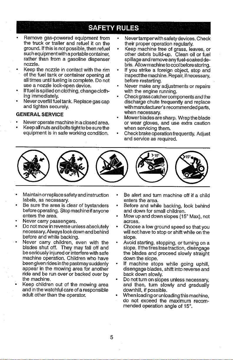
• Mow up anddown slopes (15° Max), not
across.
• Choose a low ground speed so that you
will not have to stop or shift while on the
slope.
. Avoid starting, stopping, or turnir)g on a
slope, lfthe tires lose traction, dis6ngage
the blades and proceed slowly straight
down the stope.
• If machine stops while going uphill,
disengage blades, shift into reverse and
back down slowly.
• Do not turn on slopes unless necessary,
and then, turn slowly and gradually
downhill, if possible.
• When loading or unloadingthis machine,
do not exceed the maximum recom-
mended operation angle of 15°.
5
Page 6
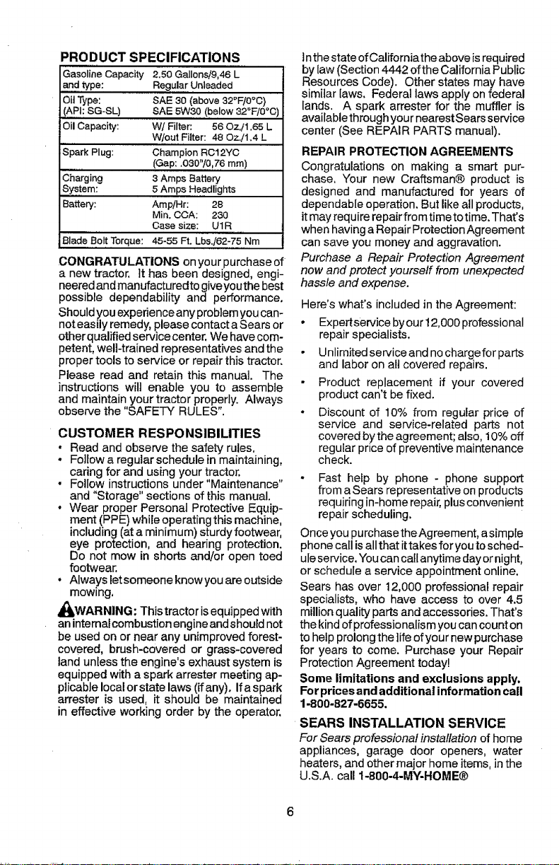
PRODUCT SPECIFICATIONS
Gasoline Capacity 2.50 Gallonsi9,46 L
and type: Regular Unleaded
Oil Type: SAE 30 (above 32°F/0°C)
(APh SG-SL) SAE 5W30 (below 32°F/0°C '
Oil Capacity: W/Filter: 56 Oz,i1,65 L
Spark Plug: Champion RC12YC
Charging 3 Amps Batlery
System: 5 Amps Headlights
Battery: Amp/Hr: 28
Blade Bolt Torque: 45-55 Ft. Lbs./62-75 Nm
W/out Filter: 48 OzJ1.4 L
(Gap: .030"/0,76 mm)
Mir_, CCA; 230
Case size: U1R
CONGRATULATIONS onyour purchase of
a new tractor, tt has been designed, engi-
neeredand manufacturedtogiveyouthe best
possible dependability and performance,
Shouldyou experience any problemyou can-
not easily remedy, please contact aSears or
other qualified service center. We havecom-
petent, well-trained representatives and the
proper tools to service or repair this tractor.
Please read and retain this manual. The
instructions will enable you to assemble
and maintain your tractor properly. Always
observe the "SAFETY RULES".
CUSTOMER RESPONSIBILITIES
• Read and observe the safety rules,
- Follow a regular schedule in maintaining,
caring for and using your tractor.
• Follow instructions under "Maintenance"
and "Storage" sections of this manual.
• Wear proper Personal Protective Equip-
ment (PPE) while operating this machine,
including (at aminimum) sturdy footwear,
eye protection, and hearing protection.
Do not mow in shorts and/or open toed
footwear.
• Always letsomeone knowyou are outside
mowing,
_WARNING: This tractor isequipped with
aninternal combustion engine andshould not
be used on or near any unimproved forest-
covered, brush-covered or grass-covered
landunless the engine's exhaust system is
equipped with a spark arrester meeting ap-
plicable local or state laws (if any). Ifa spark
arrester is used, it should be maintained
in effective working order by the operator,
Inthe state of Californiathe above isrequired
by law (Section4442 ofthe California Public
Resources Code). Other states may have
similar laws. Federal laws apply on federal
lands. A spark arrester for the muffler is
availablethrough your nearestSearsservice
center (See REPAIR PARTS manual).
REPAIR PROTECTION AGREEMENTS
Congratulations on making a smart pur-
chase, "four new Craftsman@ product is
designed and manufactured for years of
dependable operation. But like all products,
itmay require repairfrom time to time. That's
when having a Repair Protection Agreement
can save you money and aggravation.
Purchase a Repair Protection Agreement
now and protect yourself from unexpected
hassle and expense.
Here's what's included in the Agreement:
• Expertservice byour 12,000 professional
repair specialists.
• Unlimited service and nochargefor parts
and labor on all covered repairs.
Product replacement if your covered
product can't be fixed.
• Discount of 10% from regular price of
service and service-related parts not
covered bythe agreement; also, 10%off
regular price of preventive maintenance
check.
Fast help by phone - phone support
from a Sears representative on products
requiring in-home repair,plusconvenient
repair scheduling.
Onceyou purchase theAgreement, asimple
phone call isallthat ittakes for you tosched-
uleservice. Youcan callanytime dayornight,
or schedule a service appointment online.
Sears has over 12,000 professional repair
specialists, who have access to over 4.5
million quality parts and accessories, That's
the kind of professionalism you cancount on
to help prolongthe life of your new purchase
for years to come. Purchase your Repair
Protection Agreement today!
Some limitations and exclusions apply.
Forprices and additional information call
1-800-827-6655.
SEARS INSTALLATION SERVICE
For Sears professional installation of home
appliances, garage door openers, water
heaters, and other major home items, in the
U.S.A. call 1-800-4-MY-HOME®
Page 7
Keys
Slope Sheet
(1) QuickConnect
Key(s)
Your new tractor has been assembled at the factory with the exception of those parts left
unassembled for shipping purposes.
TOOLS REQUIRED FOR ASSEMBLY
A socket wrench set wil! make assembly
easier. Standard wrench sizes are listed.
(1) 1/2" wrench Tire pressure gauge
(2) 7/16" wrenches Utility knife
Pliers
When right or left hand is mentioned in this
manual,itmeanswhenyouareintheoperating
position (seated behind the steering wheel).
TO REMOVE TRACTOR FROM
CARTO N
UNPACK CARTON
• Remove all accessible loose parts and
partscartons from carton,
• Cut along dotted lines on all four panels
of carton. Remove end panels and lay
side panels flat.
• Check for any additional loose parts or
cartons and remove,
BEFORE REMOVING TRACTOR
FROM SKID
TO CHECK BATTERY
t. Lift seat to raised position.
NOTE: If this battery is put into service after
month and year indicated on label (label is
located between terminals) charge battery
forminimum ofone hour at 6-10 amps. (See
"BATTERY" in Maintenance section of this
manual for charging instructions).
• Forbattery and battery cable installation
see "REPLACING BATTERY" in the
"Service and Adjustments" section in
this manual.
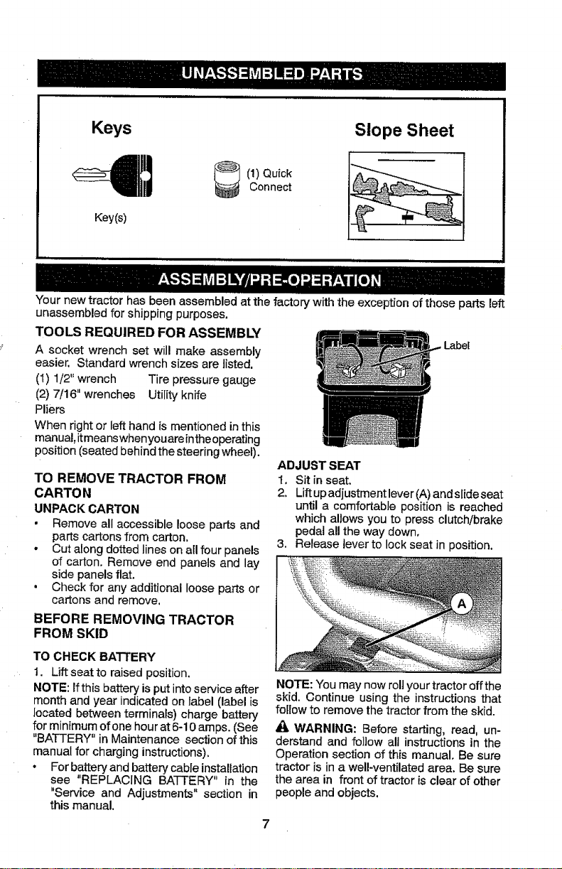
ADJUST SEAT
I, Sit in seat.
2. Liftupadjustment lever (A) and slide seat
until a comfortable position is reached
which allows you to press clutch/brake
pedal all the way down.
3. Release lever to lock seat in position.
NOTE: You may now roll yourtractor offthe
skid. Continue using the instructions that
fellow to remove the tractor from the skid.
WARNING: Before starting, read, un-
derstand and follow all instructions in the
Operation section of this manual. Be sure
tractor is in a well-ventilated area. Be sure
the area in front of tractor is clear of other
people and objects.
1
Label
Page 8
TO ROLL TRACTOR OFF SKID (See
Operation section for location and
function of controls)
I. Raise attachment lift lever to its highest
position.
2, Release parking brake by depressing
clutch/brake pedal,
3. Place gearshift lever inneutral position.
4. Roll tractor forward off skid.
5. Remove banding holding the deflector
shield up against tractor,
Continue with the instructions that follow.
CHECK TIRE PRESSURE
The tireson your tractor were ovednflated at
the factory for shipping purposes. Correct
tire pressure is important for best cutting
performance.
• Reduce tire pressure to PSI shown on
tires.
CHECK DECK LEVELNESS
For best cutting results, mower housing
should be properly leveled. See "TO LEVEL
MOWER" in the Service and Adjustments
section of this manual.
CHECK FOR PROPER POSITION
OF ALL BELTS
See the figures that are shown for replac-
ingmotion and mower blade drive belts in
the Service and Adjustments section of this
manual. Verify that the belts are routed
correctly,
CHECK BRAKE SYSTEM
After you learn how to operate your tractor,
check to see that the brake is operating
properly, See "TO CHECK BRAKE" in the
Service and Adjustments section of this
manual.
tt_ CHECKLIST
Before you operate your new tractor, we
wish to assure that you receive the best
performance and satisfaction from this
Quality Product.
Please review the following checklist:
J" All assembly instructions have been
completed.
vf No remaining looseparts in carton.
V" Battery is properly prepared and charged.
J" Seat is adjusted comfortably and tight-
ened securely.
vt All tires are properly inflated. (For ship-
ping purposes, thetires were overinflated
at the factory).
J Be sure mower deck is properlyleveled
side-to-sideifront-to-rear for best cutting
results. _ires must be properly inflated
for leveling).
J" Check mower and drive belts. Be sure
they are routed properlyaround pulleys
and insideall belt keepers.
V" Check wiring. Seethatall connections are
stillsecureandwiresareproperlyclamped,
Whilelearning howto useyourtractor,payex-
traattentiontothe following important items:
v_ Engine oil is at proper level.
J" Fuel tank is filled with fresh,clean, regular
unleaded gasoline.
J Become familiar with all controls, their
location and function. Operate them
before you start the engine.
v" Besure brake system is insafe operating
condition.
J" Be sure Operator Presence System and
Reverse Operation System (ROS) are
working properly (See theOperation and
Maintenance sections in this manual),
Page 9
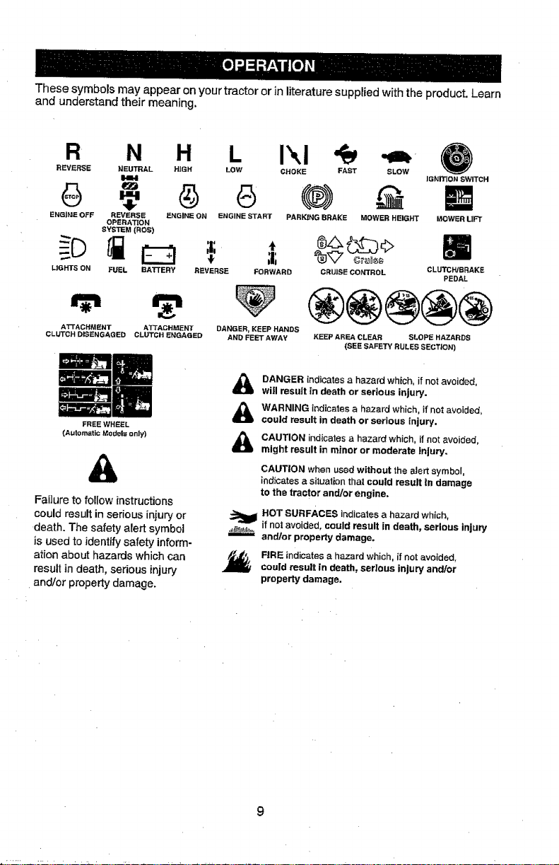
Thesesymbolsmayappearonyourtractororinliteraturesuppliedwiththeproduct.Learn
andunderstandtheirmeaning.
R N H L i_,1 _m-
REVERSE NEU'I3RAL HiGH LOW CHOKE FAST
_ZJ
SLOW
IGNmON SWITCH
6 G
ENGINE OFF REVERSE ENGINE ON ENGINE START
OPERATION
SYSTEM {ROS)
MOWER HEIGHTPARKING BRAKE MOWER LIFT
i
L1GHTS ON BAI'rERY REVERSE FORWARD CRUISE CONTROL CLUTCH/BRAKE
AI-rACHMENT ATTACHMENT DANGER, KEEP HANDS
CLUTCH DISENGAGED CLUTCH ENGAGED AND FEET AWAY
Failure to follow instructions
could result in serious injury or
death. The safety alert symbol
is used to identify safety inform-
atfon about hazards which can
result in death, serious injury
and/or property damage.
FUEL
FREE WHEEL
(Autort_ti¢ Mo_|a only)
KEEP AREA CLEAR SLOPI_ HAZARDS
(SEE SAFE'IV RULES SECTION)
DANGER indicates a hazard which, if not avoided,
&
will result in death or serious injury.
WARNING indicates a hazard which, if not avoided,
&
could result in death or serious injury.
CAUTION indicates a haza_t which, it not avoided,
&
might result in minor or moderate injury.
CAUTION when used without the _ert symbol
indicates a situation that could result in damage
to the tractor andlor engine,
HOT SURFACES indicates a hazard which,
if not avoided, could result in death, serious injury
andlor property damage.
FIRE indicates a hazard which, it not avoided.
could result in death, serious injury and/or
property damage,
PEDAL
Page 10
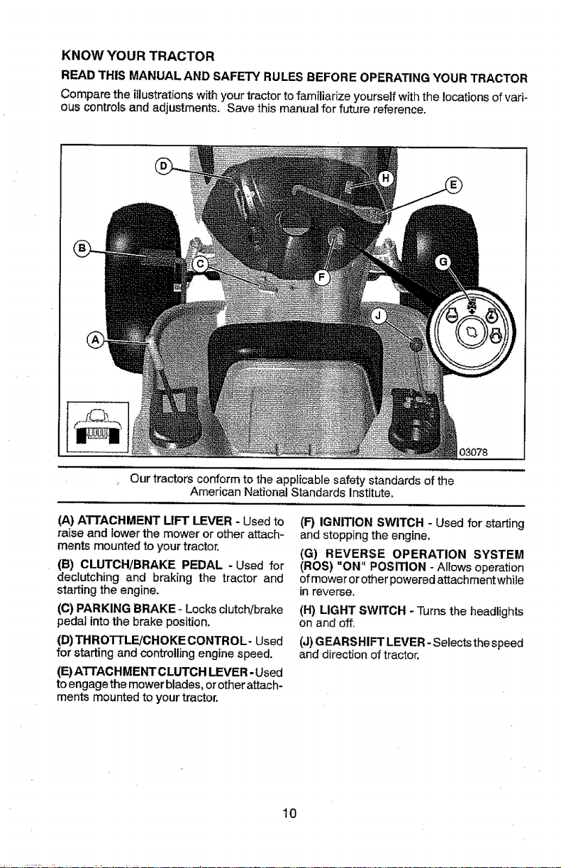
KNOW YOUR TRACTOR
READ THIS MANUAL AND SAFETY RULES BEFORE OPERATING YOUR TRACTOR
Compare the illustrationswithyour tractorto familiarize yourself withthe locationsof vari-
ous controls and adjustments. Save this manual for future reference.
03078
Our tractors conform to the applicable safety standards of the
American National Standards institute.
(A) ATTACHMENT LIFT LEVER - Used to
raise and lowerthe mower or other attach-
ments mounted to your tractor.
(B) CLUTCH/BRAKE PEDAL -Used for
decIutching and braking the tractor and
starting the engine.
(C) PARKING BRAKE - Locks clutch/brake
pedal intothe brake position.
(D)THROTTLF-JCHOKECONTROL- Used
for starting and controlling engine speed.
(E)ATTACHMENTCLUTGH LEVER-Used
to engage the mower blades, or other attach-
ments mounted to your tractor.
(F) IGNITION SWITCH - Used for starting
and stopping the engine.
(G) REVERSE OPERATION SYSTEM
(ROS) "ON" POSITION -Ailows operation
of mower or other powered attachment while
in reverse.
(H) LIGHT SWITCH - Turns the headlights
on and off.
(J)GEARSHIFT LEVER- Selects the speed
and direction of tractor.
10
Page 11
The operation of any tractor can result in foreign objects thrown into the eyes,I
which can result in severe eye damage. Always wear safety glasses or eye_
shields while operating your tractor or performing any adjustments or repairs.I
We recommend standard safety glasses or a wide vision safety mask worr_
over spectacles. |
HOW TO USE YOUR TRACTOR
TO SET PARKING BRAKE
Your tractor is equipped with an operator
presence sensing switch. When engine is
running, any attempt bythe operator toleave
theseat withoutfirst setting the parkingbrake
will shut off the engine.
1. Depress clutch!brake pedal (B) all the
way down and hold.
2. Pull parking brake lever ((3)up and hold,
release pressure from brake pedal (B),
then release parking brake lever. Pedal
should remain in brake position. Ensure
parking brake will hold tractor secure.
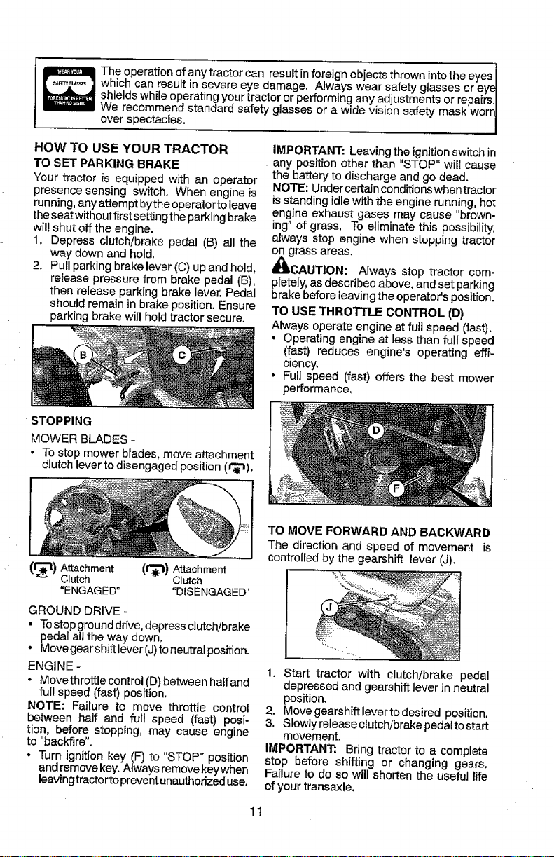
STOPPING
MOWER BLADES -
• To stop mower blades, move attachment
Clutch lever to disengaged position (¢_).
(t'_11) Attachment (1_) Attachment
Clutch Clutch
"ENGAGED .... DISENGAGED"
GROUND DRIVE -
• Tostop ground drive, depress clutch/brake
pedal all the way down,
° Move gear shiftlever (J)to neutral position.
ENGINE -
• Movethrottle control (D) between halfand
fulI speed (fast) position,
NOTE: Failure to move throttle control
between half and full speed (fast) posi-
tion, before stopping, may cause engine
to "bac_re".
• Turn ignition key (F) to "STOP" position
and removekey.Always removekey when
leavingtractor to preventunauthorized use.
IMPORTANT: Leaving the ignition switch in
any position other than "STOP" will cause
the battery to discharge and go dead.
NOTE: Under certainconditions when tractor
is standing idle with the engine running, hot
engine exhaust gases may cause "brown-
ing" of grass. To eliminate this possibility,
always stop engine when stopping tractor
on grass areas.
_bCAUTION: Always stop tractor com-
pletely, as described above, and set parking
brake before leaving the operator's position.
TO USE THROTTLE CONTROL (D)
Always operate engine at full speed (fast).
• Operating engine at less than full speed
(fast) reduces engine's operating effi-
ciency.
• Full speed (fast) offers the best mower
performance,
TO MOVE FORWARD AND BACKWARD
The direction and speed of movement is
controlled by the gearshift lever (J).
1. Start tractor with clutch/brake pedal
depressed and gearshift lever in neutral
position.
2. Move gearshift lever to desired position,
3. Slowly release clutch/brake pedal tostart
movement.
IMPORTANT: Bring tractor to a complete
stop before shifting or changing gears.
Failure to do so will shorten the useful life
of your transaxle.
11
Page 12
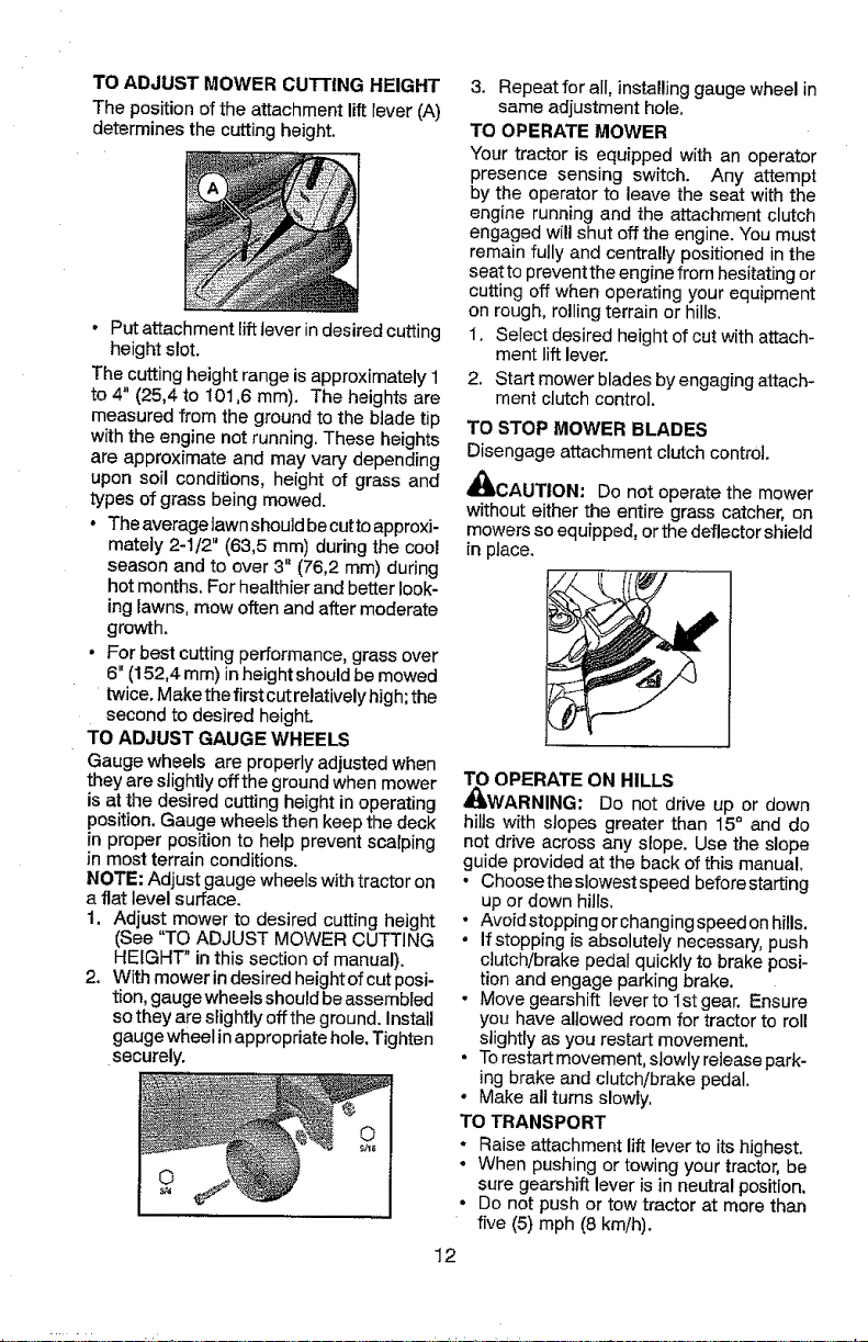
TO ADJUST MOWER CUTTING HEIGHT
The position of the attachment lift Fever(A)
determines the cutting height.
• Put attachment lift leverin desired cutting
height slot.
The cutting height range is approximately 1
to 4" (25,4 to t01,6 ram). The heights are
measured from the ground to the blade tip
with the engine not running. These heights
are approximate and may vary depending
upon soil conditions, height of grass and
types of grass being mowed.
° The averagelawn should becutto approxi-
mately 2-1/2" (63,5 ram) during the cool
season and to over 3" (76,2 ram) during
hot months. For healthier and better look-
inglawns, mow often and after moderate
growth.
• For best cutting performance, grass over
6" (152,4 ram) in height should be mowed
twice.Make the first cut relatively high;the
second to desired height.
TO ADJUST GAUGE WHEELS
Gauge wheels are properly adjusted when
they are slightly off the ground when mower
is atthe desired cutting height in operating
position. Gauge wheels then keep the deck
in proper position to help prevent scalping
in most terrain conditions.
NOTE: Adjust gauge wheels with tractor on
a flat level surface.
1. Adjust mower to desired cutting height
(See "TO ADJUST MOWER CUTTING
HEIGHT" in this section of manual).
2+ With mower indesired heightof cut posi-
tion, gauge wheels should beassembled
sothey are slightly offthe ground. Install
gauge wheel inappropriate hole, Tighten
securely.
3. Repeat for all, installinggauge wheel in
same adjustment hole.
TO OPERATE MOWER
Your tractor is equipped with an operator
presence sensing switch. Any attempt
by the operator to leave the seat with the
engine running and the attachment clutch
engaged will shut off the engine. You must
remain fully and centrally positioned in the
seat to prevent the engine from hesitating or
cutting off when operating your equipment
on rough, rolling terrain or hills.
1, Select desired height of cut with attach-
ment lift lever.
2. Start mower blades by engaging attach-
ment clutch control
TO STOP MOWER BLADES
Disengage attachment clutch control.
_.CAUTION: Do not operate the mower
without either the entire grass catcher, on
mowers so equipped, orthe deflector shield
in place,
N.-
TO OPERATE ON HILLS
_WARNING: Do not drive up or down
hills with slopes greater than 15+ and do
not drive across any slope. Use the slope
guide provided at the back of this manual,
• Choose the slowest speed before starting
up or down hills,
• Avoidstopping orchanging speed onhills,
• If stopping isabsolutely necessary, push
clutch/brake pedal quickly to brake posi-
tion and engage parking brake.
- Move gearshift leverto lstgear. Ensure
you have allowed room for tractor to roll
slightly as you restart movement.
• Torestart movement, stowly release park-
ing brake and clutch/brake pedal.
• Make all turns slowly,
TO TRANSPORT
- Raise attachment lift Feverto its highest.
• When pushing or towing your tractor, be
sure gearshift lever is in neutral position,
• Do not push or tow tractor at more than
five (5) mph (8 kin/h).
12
Page 13
NOTE: Toprotect hoodfrom damage when
transporting yourtractoron atruck oratrailer,
besure hood isclosed andsecured totractor,
Use an appropriate means of tying hood to
tractor (rope, cord, etc.).
TOWING CARTS AND OTHER ATTACH-
MENTS
Tow only the attachments that are recom-
mended by and complywith specifications
of the manufacturer of your tractor. Use
common sense when towing. Too heavy of
aload, while on aslope, isdangerous. Tires
can lose traction with the ground and cause
you to lose control of your tractor.
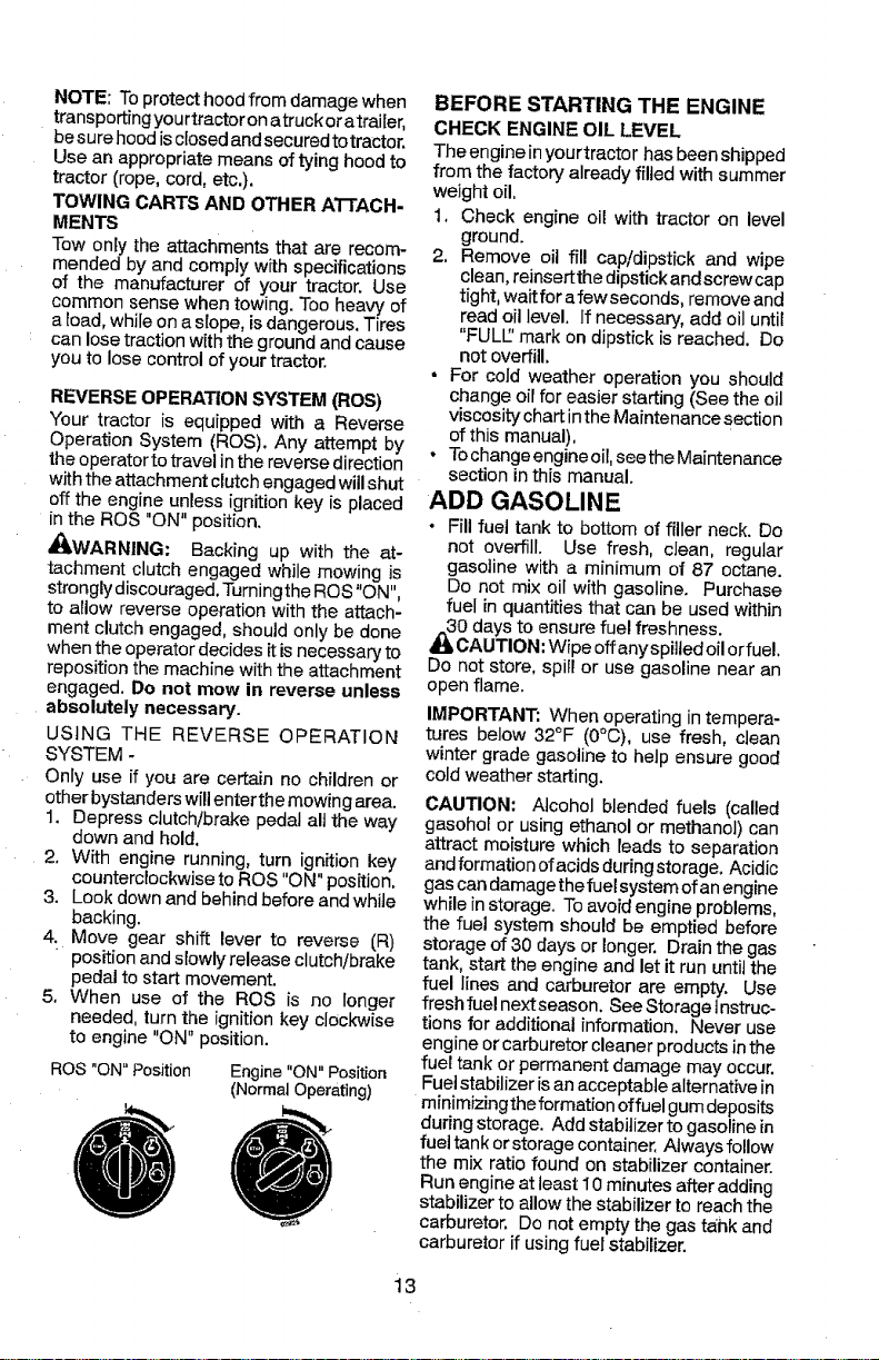
REVERSE OPERATION SYSTEM (ROS)
Your tractor is equipped with a Reverse
Operation System (ROS). Any attempt by
the operator to travel inthe reverse direction
with the attachment clutch engaged will shut
off the engine unless ignitionkey is placed
in the ROS "ON" position.
_kWARNING: Backing up with the at-
tachment clutch engaged while mowing is
strongly discouraged. Turningthe ROS"ON",
to allow reverse operation with the attach-
ment clutch engaged, should only be done
when the operator decides itisnecessary to
reposition the machine with the attachment
engaged. Do not mow in reverse unless
absolutely necessary.
USING THE REVERSE OPERATION
SYSTEM -
Only use if you are certain no children or
other bystanders will enter the mowing area.
1. Depress clutch/brake pedal aUthe way
down and hold.
2, With engine running, turn ignition key
counterclockwise to ROS "ON" position.
3. Look down and behind before and white
backing.
4. Move gear shift lever to reverse (R)
" position and slowly release clutchibrake
pedal to start movement.
5. When use of the ROS is no longer
needed, turn the ignitionkey clockwise
to engine "ON" position.
ROS "ON" Position
Engine "ON" Position
(Normal Operating)
BEFORE STARTING THE ENGINE
CHECK ENGINE OIL LEVEL
The engine inyourtractor has been shipped
from the factory already filied with summer
weight oil.
1. Check engine oil with tractor on level
ground.
2. Remove oil fil! cap/dipstick and wipe
clean,reinsertthe dipstick and screw cap
tight, wait for afew seconds, remove and
read oil level. If necessary, add oil until
"FULL:'mark on dipstick is reached. Do
not overfill,
• For cold weather operation you should
change oil for easier starting (See the oil
viscosity chart inthe Maintenance section
ofthis manual),
• Tochange engine oil, seethe Maintenance
section inthis manual.
ADD GASOLINE
• Fill fuel tank to bottom of filler neck. Do
not overfill. Use fresh, clean, regular
gasoline with a minimum of 87 octane.
Do not mix oit with gasoline. Purchase
fuel in quantities that can be used within
0 days to ensure fuel freshness.
CAUTION: Wipe offany spiItedoil orfuel,
Do not store, spill or use gasoline near an
open flame.
IMPORTANT: When operating in tempera-
tures below 32°F (0°C), use fresh, clean
winter grade gasoline to help ensure good
cold weather starting,
CAUTION: Alcohol blended fuels (called
gasohol or using ethanol or methanol) can
attract moisture which leads to separation
andformation ofacidsduring storage, Acidic
gas can damagethe fuel system ofan engine
while in storage. To avoid engine problems,
the fuel system should be emptied before
storage of 30 days or longer, Drain the gas
tank, start the engine and let it run until the
fuel lines and carburetor are empty. Use
freshfuel nextseason. See Storageinstruc-
tions for additional information. Never use
engine or carburetor cleaner products inthe
fuel tank or permanent damage may occur.
Fuelstabilizer is anacceptable alternative in
minimizingthe formation offuel gum deposits
during storage. Add stabilizer to gasoline in
fuel tank orstorage container, Always follow
the mix ratio found on stabilizer container.
Runengine atleast 10 minutes after adding
stabilizer to allow the stabilizer to reach the
carburetor. Do not empty the gas tahk and
carburetor if using fuel stabilizer.
13
Page 14
TO START ENGINE
When starting the engine for the first time or
if the engine has run out of fuel, it will take
extra cranking time to move fuel from the
tank to the engine.
1. Siton seatin operating position, depress
clutch/brake pedalandset parking brake.
2. Place gear shift lever in neutralposition.
3. Move attachment clutch to disengaged
position.
4. Move throttle control to choke position.
NOTE: Before starting, read the warm and
cold starting proceduresbelow,
5. Insert key into ignition and turn key
clockwise to start position and release
key assoon as engine starts. Do not run
starter continuouslyfor more than fifteen
seconds per minute. If the engine does
not start after several attempts, move
throttle control to fast position, wait a
few minutes andtry again, Ifengine still
does not start, move the throttle control
back to the choke position and retry.
WARM WEATHER STARTING
(50°F (10°C) and above)
6. When engine starts, move the throttle
control to the fast position.
• The attachments and ground drive
can now be used. tf the engine does
not accept the load, restart the engine
and allow itto warm up forone minute
using the choke as described above.
COLD WEATHER STARTING
(50°F (10°C) and below)
6. When engine starts, leavethrottle control
in choke position until engine warms up
and begins to run roughly. Once rough
running begins, immediately move the
throttle controlto thefast position. Engine
warm-up maytake from several seconds
to several minutes (the colder the tem-
perature, the longer the warm-up).
• The attachments can also be used
during the engine warm-up period.
MOWING TIPS
• DO NOT use tire chains when the mower
housing is attached to tractor.
• Mower should beproperty leveledforbest
mowing performance. See "TO LEVEL
MOWER HOUSING" in the Service and
Adjustments section of this manual.
• The left hand side of mower should be
used for trimming.
• Drive so that clippings aredischarged onto
the area that has already been cut. Have
the cut areatothe right ofthetractor. This
will result in a more even distribution of
clippings and more uniform cutting.
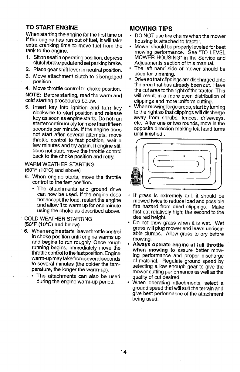
• When mowing large areas, start byturning
to the right so that clippings will discharge
away from shrubs, fences, driveways,
etc. After one or two rounds, mow inthe
opposite direction making left hand turns
until finished.
• If grass is extremely tall, it should be
mowed twice to reduce load and possible
fire hazard from dried clippings. Make
first cut relatively high; the second to the
desired height.
• Do not mow grass when it is wet. Wet
grass will plug mower and leave undesir-
able clumps. Allow grass to dry before
mowing.
• Always operate engine at full throttle
when mowing to assure better mow-
ing performance and proper discharge
of material. Regulate ground speed by
selecting a low enough gear to give the
mower cutting performance as well as the
quality of cut desired.
• When operating attachments, select a
ground speed that wil!suit the terrain and
give best performanceof the attachment
being used.
14
Page 15
v"
GENERAL RECOMMENDATIONS
The warranty on this tractor does not cover
items that have been subjected to operator
abuse or negligence. To receive full vague
from the warranty, operator must maintain
tractor as instructed in this manual.
Some adjustments will need to be made
periodically to properly maintain your tractor,
At least once a season, check to see if
you should make any of the adjustments
described in the Service and Adjustments
section of this manual.
• At least once a year you should replace
the spark plug, clean or replace air filter,
and check blades and belts for wear. A
new spark plug and clean air filter assure
proper air-fuel mixture and help your en-
gine run better and last ]onger.
BEFORE EACH USE
t, Check engine oil level,
2. Check brake operation.
3. Check tire pressure.
4. Check operator presence and
Roe systems for proper operation.
5, Check for loose fasteners.
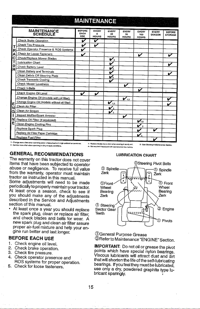
LUBRICATIONCHART
(_)SteeringPivotBolts
(_ Spind_e----__'_r---_ Spindle
Wheel _! _-_.j-_ vv .
@ Steering" _ _ _-_-_'_\_
SectorGear J_( _ J_t_J _ Engine
(_General Purpose Grease
(_Re_'er to Maintenance"ENGINE" Section.
IMPORTANT: Do not oil or grease thepivot
points which have special nylon bearings.
Viscous lubricants will attract dust and dirt
that willshorten the lifeofthe self-lubricating
bearings. Ifyou feet they must be lubricated,
use only a dry, powdered graphite type lu-
bricant sparingly.
15
Page 16
TRACTOR
Always observe safety rules when perform-
ing any maintenance.
BRAKE OPERATION
If tractor requires more than 5 feet (1,5 m)
to stop at highest speed in highest gear on
a level, dry concrete or paved surface, then
brake must be serviced. (See "TO CHECK
BRAKE" in the Service and Adjustments
section of this manual).
TIRES
• Maintain proper air pressure in all tires
(See the side of tires for proper PSI,)
° Keep tires free of gasoline, oil, or insect
control chemicals which can harm rubber.
• Avoid stumps, stones, deep ruts, sharp
objects and other hazards that may cause
tire damage.
NOTE: To seal tire punctures and prevent
flat tires due to slow leaks, tire sealant may
be purchased from your local parts dealer.
Tire sealant also prevents tire dry rot and
corrosion.
OPERATOR PRESENCE SYSTEM AND
REVERSE OPERATION SYSTEM (ROS)
Be sure operator presence and reverse
operation systems are working properly. If
your tractor does not function as described,
repair the problem immediately.
• The engine should not start unless the
brake pedal is fully depressed, and the
attachment clutch control is in the disen-
gaged position.
CHECK OPERATOR PRESENCE SYSTEM
• When the engine is running, any attempt
by the operator to leave the seat without
first setting the parking brake should shut
off the engine.
• When the engine is running and the at-
tachment clutch is engaged, any attempt
by the operator to leave the seat should
shut off the engine.
• The attachment clutch should never oper-
ate unless the operator is in the seat.
CHECK REVERSE OPERATION (ROS)
SYSTEM
• Whenthe engine isrunningwith theignition
switch inthe engine"ON" position andthe
attachment clutch engaged, any attempt
by the operator to drive in reverse should
shut off the engine.
• When theengine isrunningwiththe ignition
switch in the ROS "ON" position and the
attachment clutch engaged, any attempt
bythe operator to drive in reverse should
NOT shut off the engine.
Ros "On" Engine "On" Position
Position (Normal Operating)
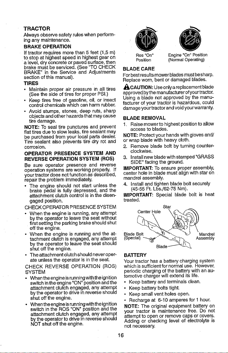
BLADE CARE
Forbestresults mower bladesmustbesharp.
Replace worn, bent or damaged blades.
CAUTION: Useonly a replacementblade
approved bythe manufacturer of yourtractor.
Using a blade not approved by the manu-
facturer of your tractor is hazardous, could
damage your tractor andvoidyourwarranty.
BLADE REMOVAL
1. Raise mower to highest positionto allow
access to blades,
NOTE: Protect your hands with gloves and!
or wrap blade with heavy cloth.
2. Remove blade bolt by turning counter-
clockwise,
3. Install new bladewith stamped "GRASS
SIDE" facing the ground.
IMPORTANT: To ensure proper assembly,
center hole in blade must align with star on
mandrel assembly.
4. Install and tighten blade bolt securely
(45-55 Ft. Lbs./62-75 Nm).
IMPORTANT: Special blade bolt is heat
treated.
Center Hole
8lade Bolt Mandrel
Star
(Special)_-_'" Assembly
Blad_
BATTERY
Your tractor has a battery charging system
which issufficient for normal use. However,
periodic charging of the battery with an au-
tomotive charger will extend its life.
° Keep battery and terminals clean.
• Keep battery bolts tight.
• Keep small vent holes open.
• Recharge at 6-10 amperes for 1 hour.
NOTE: The original equipment battery on
your tractor is maintenance free. Do not
attempt to open or remove caps or covers.
Adding or checking level of electrolyte is
not necessary.
16
Page 17
TO CLEAN BATTERY AND TERMINALS
Corrosion anddirt onthe batteryand terminals
can cause the battery to "leak" power.
1. Remove terminal guard.
2. Disconnect BLACK battery cable first
then RED battery cable and remove
battery from tractor,
3. Rinse the battery with plain water and
dry.
4. Clean terminals and battery cable ends
with wire brush until bright.
5. Coatterminals with grease or petroleum
jelly,
6. Reinstall battery(See"REPLACING BAT-
TERY" in the Service and Adjustments
section of this manual).
TRANSAXLE MAINTENANCE
Keep transaxle free from build-up of dirt and
chaff which can restrict cooling.
Do not attempt to clean transaxle while
engine is running or while the transaxle is
hot. To prevent possible damage to seals,
do not use high pressure water or steam to
clean transaxle.
V-BELTS
Check V-belts fordeterioration and wear after
100 hours of operation and replace ff neces-
sary. The belts are not adjustable, Replace
belts if they begin to slip from wear.
ENGINE
LUBRICATION
Only use high quality detergent oil rated with
API service classification SG-SL. Selectthe oil's
SAE viscosity grade according to your expected
operating temperature.
F *_0 0 3O 32 48 SO 80 _OO
_EM_ ERt*TLIRER#,NG£At,rrlCi'_,ATEOBEFOREN_3_qOILC_tGE
NOTE: Although multi-viscosity oils (5W30,
10W30 etc,) improve starting in cold weather,
they will result in increased oif consumption when
used above 32°F/0_C, Check your engine oillevel
more frequentlyto avoid possible engine damage
from running low on oil.
Change the oil after every 50 hours of operation
or at least once a year if the tractor is not used
for 50 hoursin one year.
Check the crankcase oil level before starting the
engine and after each eight (8) hours ofoperation.
Tighten oilfill cap/dipstick securely each time you
check the oil level.
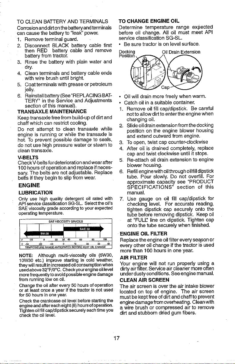
TO CHANGE ENGINE OIL
Determine temperature range expected
before oil change. All oil must meet API
service classification SG-SL.
• Be sure tractor is on [evel surface.
Docking Oil Drain Extension
Positi
• Oil will drain more freely when warm.
• Catch oil ina suitable container.
1. Remove oil fill cap/dipstick. Be careful
not to allow dirt to enterthe engine when
changing oil.
2. Slide oildrain extension from thedocking
position on the engine blower housing
and extend outward from engine.
3. To open, twist cap counter-clockwise
4. After oil is drained completely, replace
cap and twist clockwise until it stops.
5. Re-attach oil drain extension to engine
blower housing.
6. Refillengine with oilthrough oilfill dipstick
tube. Pour slowly. Do not overfill For
approximate capacity see "PRODUCT
SPECIFICATIONS" section of this
manual.
7. Use gauge on oil fill cap/dipstick for
checking level. For accurate reading,
tighten dipstick cap securely onto the
tube before removing dipstick, Keep oil
at "FULl.'.'line on dipstick. Tighten cap
onto the tube securely when finished.
ENGINE OIL FILTER
Replace the engine oilfilter every season or
every other oil change if the tractor is used
more than 100 hours in one year,
AIR FILTER
Your engine will not run properly using a
dirty air filter. Service air cfeaner more often
underdusty conditions. See engine manual,
CLEAN AIR SCREEN
The airscreen is overthe air intake blower
located on top of engine, The air screen
must be keptfree of dirt and chaffto prevent
engine damagefrom overheating. Cleanwith
a wire brush or compressed air to remove
dirt and stubborn dried gum fibers.
17
Page 18
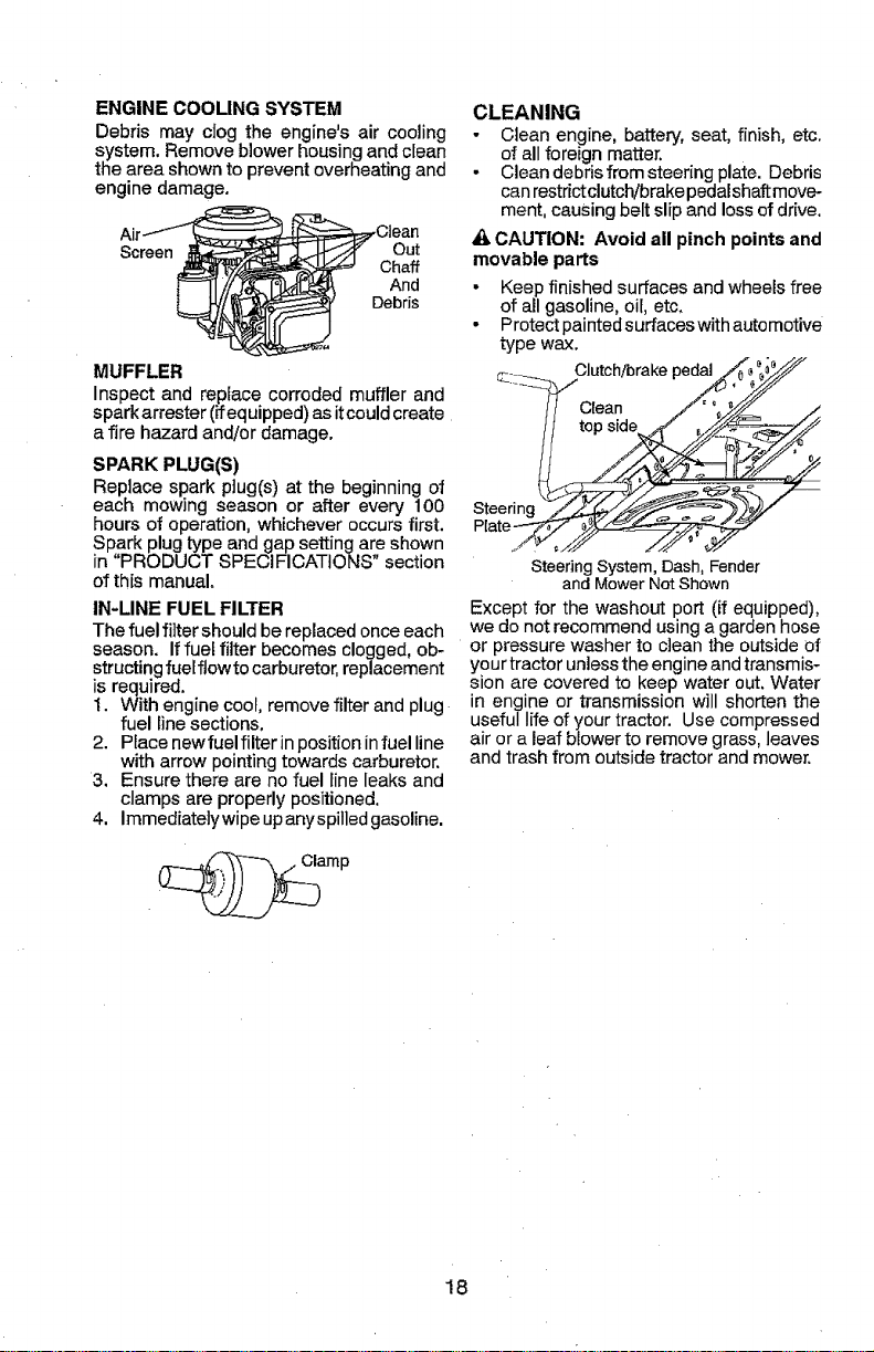
ENGINE COOLING SYSTEM
Debris may clog the engine's air cooling
system, Remove blower housing and clean
the area shown to prevent overheating and
engine damage.
A_ _..-X Out
;_ Cha_
MUFFLER
Inspect and replace corroded muffler and
spark arrester (ffequipped)asitcouldcreate
afire hazard and/or damage.
SPARK PLUG(S)
Replace spark plug(s) at the beginningof
each mowing season or after every 100
hours of operation,whichever occursfirst.
Spark plug type and gap setting are shown
in "PRODUCT SPECIFICATIONS" section
of this manual.
IN-LINE FUEL FILTER
The fuel filter should be replaced once each
season. Iffuef filter becomes clogged, ob-
structing fuelflowto carburetor, replacement
is required.
1. With engine coot, remove filter and plug
fuel line sections.
2. Place newfuelfilter inposition infuel line
with arrow pointing towards carburetor.
3. Ensure there are no fuel line leaks and
clamps are properly positioned.
4. Immediatelywipe upanyspilled gasoline.
CLEANING
• Clean engine, battery, seat, finish, etc.
of all foreign matter.
• Clean debris from steering plate. Debris
can restrictclutch/brake pedalshaft move-
ment, causing belt slip and loss of drive.
& CAUTION: Avoid all pinch points and
movable parts
• Keep finished surfaces and wheelsfree
of all gasoline, oil, etc.
- Protect painted surfaces with automotive
type wax.
Clutch/brakepedal
SteeringSystem,Dash,Fender
andMowerNotShown
Except for the washout port (if equipped),
we do not recommend usinga garden hose
or pressure washer to clean the outside of
your tractor unless the engine and transmis-
sion are covered to keep water out, Water
in engine or transmission will shorten the
useful life of your tractor. Use compressed
air or a leaf blower to remove grass, leaves
and trash from outside tractor and mower.
_amp
18
Page 19
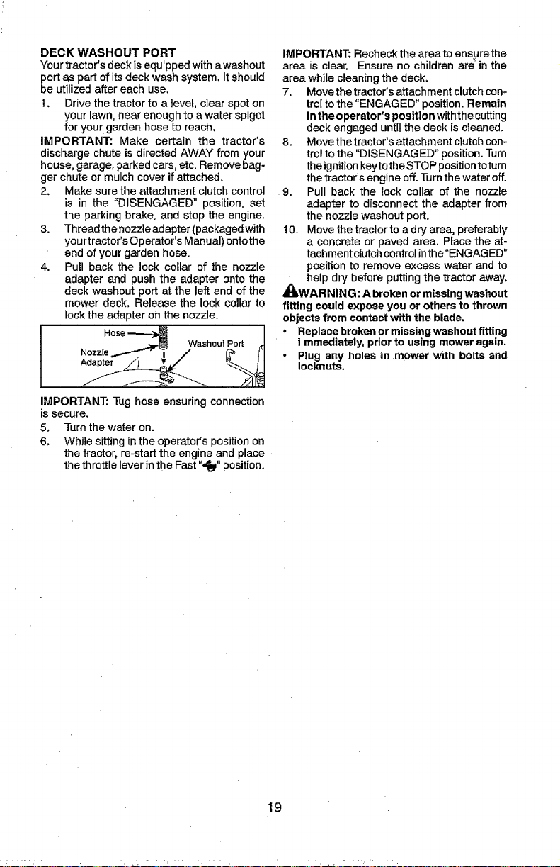
DECK WASHOUT PORT
Your tractor'sdeck is equipped with awashout
port as part of itsdeck wash system. It should
be utilized after each use.
1. Drive the tractor to a level, clear spot on
your lawn, near enough to a water spigot
for your garden hose to reach,
IMPORTANT: Make certain the tractor's
discharge chute is directed AWAY from your
house, garage, parked cars, etc. Remove bag-
ger Chute or mulch cover if attached.
2. Make sure the attachment clutch control
is in the "DISENGAGED" position, set
the parking brake, and stop the engine.
3. Threadthenozzleadapter(packagedwith
your tractor's Operator's Manual) ontothe
end of your garden hose.
4. Pull back the lock collar of the nozzle
adapter and push the adapter onto the
deck washout port at the left end of the
mower deck, Release the lock collar to
lockthe adapter on the nozzle.
Hose
N°zzle---"'_ i ......._'" _I
IMPORTANT: Tug hose ensuring connection
is secure.
5, Turn the water on.
6, While sitting in the operator's position on
the tractor, re-start the engine and place
the throttle lever in the Fast ",_" position.
IMPORTANT: Recheckthe areato ensurethe
area is clear. Ensure no children are' in the
area while cleaning the deck.
7. Move the tractor's attachment clutch con-
tro[ to the "ENGAGED" position. Remain
in the operator's position withthe cutting
deck engaged until the deck is cleaned.
8. Move the tractor's attachment clutch con-
trol to the "DISENGAGED" position. Turn
theignition keytothe STOP positiontoturn
the tractor's engine off. Turn the water off.
9. Pull back the lock collar of the nozzle
adapter to disconnect the adapter from
the nozzle washout port.
t0. Move the tractor to adry area, preferably
a concrete or paved area, Place the at-
tachment clutch control inthe"ENGAGED"
position to remove excess water and to
help dry before putting the tractor away,
,_k,WARNING: A broken or missing washout
fitting could expose you or others to thrown
objects from contact with the blade,
, Replace broken or missing washout fitting
i mmediately, prior to using mower again.
- Plug any holes in mower with bolts and
Iocknuts.
19
Page 20
WARNING: TO AVOID SERIOUS INJURY, BEFORE PERFORMING ANYSERVICE OR ADJUSTMENTS:
1. Depress clutch/brake pedal fully and set parking brake,
2. Place gearshift lever in neutral position.
3. Place attachment clutch in "DISENGAGED" position.
4. Turn ignition key to "STOP" and remove key.
5. Ensure the blades and all moving parts have completely stopped.
6. Disconnect spark plug wire from spark plug and place wire where it cannot
come in contact with plug,
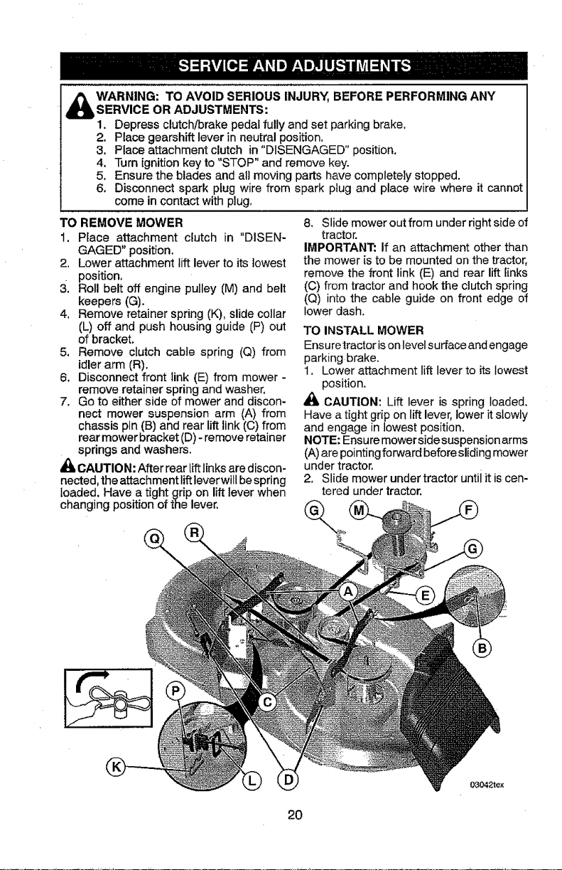
TO REMOVE MOWER
1. Place attachment clutch in "DISEN-
GAGED" position.
2, Lower attachment lift lever to its lowest
position.
3. Roll belt off engine pulley (M) and belt
keepers (G).
4, Remove retainer spring (K), slide collar
(L) off and push housing guide (P) out
of bracket.
5. Remove clutch cable spring (Q) from
idler arm (R).
6. Disconnect front link (E) from mower -
remove retainer spring and washer.
7. Go to either side of mower and discon-
nect mower suspension arm (A) from
chassis pin (B) and rear lift link (C) from
rear mower bracket (D)- remove retainer
springs and washers.
_1_CAUTION: After rear liftlinks are discon-
nected, the attachment lift leverwill bespring
loaded. Have a tight grip on lift lever when
8. Slide mower out from underright side of
tractor.
IMPORTANT: If an attachment other than
the mower is to be mounted on the tractor,
remove the front link (E) and rear lift links
(C) from tractor and hook the clutch spring
(Q) into the cable guide on front edge of
lower dash.
TO INSTALL MOWER
Ensuretractor ison levelsurface and engage
parking brake.
1. Lower attachment lift lever to its lowest
position.
_, CAUTION: Lift lever is spring loaded.
Have a tight grip on lift lever, lower it slowly
and engage in lowest position.
NOTE: Ensure mower sidesuspension arms
(A)are pointingforward beforesliding mower
under tractor.
2. Slide mower under tractor until it is cen-
tered under tractor.
changing position of the lever.
2O
03042tex
Page 21

3. ATTACH MOWER SIDE SUSPENSION
ARMS (A) TO CHASSIS - Position hole
in arm over pin (B)on outside of tractor
chassis and secure with retainer spring.
4. Repeat on opposite side of tractor.
7. Insert end of link (E) into hole in front
mower bracket (H) and secure with
washer and retainer spring {J).
5,
ATTACH REAR LIFT LINKS (C) - Lift
rear corner of mower and position slot
in link assembly over pin (D) on rear
mower bracket and secure with washer
and retainer spring.
6, ATTACH FRONT LINK (E) - Work from
left side of tractor, Insert rod end of link
assembly through front hole in tractor
front suspension bracket (F).
8. Hook end of clutch cable spring (Q) into
hole in idler arm (R).
9. Push clutch cable housing guide (P) into
bracket, slide collar (L) onto guide and
secure with retainer spring (K).
10. Install belt onto engine pulley (M) and belt
keepers (G).
IMPORTANT: Check belt for proper routing
in all mower pulley grooves.
11.Raise attachment lift lever to highest
position.
t2. If necessary, adjust gauge wheels before
operating mower as shown in the Opera-
tion section of this manual.
21
03042te×
Page 22

TO LEVEL MOWER
Ensure tires are properlyinflated to the PSI
shown on tires. If tires are over or under
inflated, it may affect the appearance of your
lawn and lead you to think the mower is not
adjusted properly.
VISUAL SIDE-TO-SIDE ADJUSTMENT
t. With all tires properly inflated and if your
lawn appears unevenly cut, determine
which side of mower is cutting lower.
2, With a 3/4" or adjustable wrench, turn
lift link adjustment nut (A) to the left to
lower LH side of mower, or, to the right
to raise LH side of mower.
Turn nut
rightto
raise
mower
Turn nut
leftto
lower
mower
NOTE: Each full turn of adjustment nut will
change mower height about 3/16" (4,7 mm),
3. Test your adjustment by mowing some
uncut grass and visually checking the
appearance, Readjust, ifnecessary, until
you are satisfied with the results,
PRECIS!ON SIDE-TO-SIDE ADJUSTMENT
1. With alttires properlyinflated, parktractor
on level ground or driveway.
_;_CAUTION: Blades are sharp. Protect
your hands with gloves and/or wrap blade
with heavy cloth.
2. Raise mower to its highest position.
3. At both sides of mower, positionblade
at side and measure distance "A" from
bottom edge of blade to ground. The dis-
tance should bethe same on bothsides.
4. Ifadjustment is necessary, see steps in
Visual Adjustment instructions above.
5, Recheck measurements; adjust ifneces-
sary until both sides are equal.
FRONT-TO-BACK ADJUSTMENT
IMPORTANT: Deck must be level side-
to-side.
To obtainthe best cutting results, the mower
blades should be adjusted so the front tip
is 1/8 to 1/2" (3,t to 12,7 ram) (lower than
the rear tip when the mower is in its highest
position,
_lh,CAUTION: Blades are sharp. Protect
your hands with gloves and/or wrap blade
with heavy cloth.
• Raise mower to highest position.
• Position any blade so the tip is pointing
straight forward. Measure distance "B" to
the ground at front and rear tip of blade.
• If front tip of blade is not 1/8 to 1/2" (3,1
to 12,7 mm) lower than the rear tip, go to
the front of tractor.
• With an 11/16" or adjustable wrench,
loosen jam nut "A" several turns to clear
adjustment nut "B".
• With a 3/4" or adjustable wrench, turn
front link adjustment nut"B" clockwise (r_)
(tighten) to raise the front of mower, or,
counterclockwise (_-_) (loosen) to lower
the front mower.
Tighten adjust Loosen adjust
nut "B" to nut "B" to
raise mower lower mower
Loosen jam nut "A" first
NOTE: Each full turn of adjustment nut will
change mower height about 1/8" (3,1 ram).
• Recheck measurements, adjust if neces-
sary until front tip of blade is 1/8 to 1/2"
(3,1 to 12,7 mm) lower than the rear tip.
• Hold adjustment nut in position with
wrench and tighten jam nut securely
against adjustment nut.
22
Page 23

TO REPLACE MOWER BLADE DRIVE
BELT
The mower bladedrive belt may be replaced
without tools. Park the tractor on level sur-
face, Engage parking brake.
BELT REMOVAL -
t. Remove mower from tractor (See "TO
REMOVE MOWER" in this section of
manual).
2. Work belt off both mandrel pulleys and
idler pulleys.
3. Pull belt away from mower,
BELT INSTALLATION -
1. Work belt around both mandrel pulleys
and idler pulleys
2. Ensure belt is in all pulley grooves and
inside all belt guides,
3. Install mower (See "To Install Mower" in
this section of this manual).
Mandrel Idler
Pulleys
Mandrel
TO REPLACE MOTION DRIVE BELT
Park the tractor on level surface. Engage
parking brake. For assistance, there is a
belt installation guide decal on bottom side
of [eft footrest.
BELT REMOVAL -
1, Remove mower (See "TO REMOVE
MOWER" in this section of manual),
NOTE: Observe entire motion drive belt
and position of all belt guides and keepers.
2. Remove belt from stationary idler (A)and
clutching idler (B),
3. Pull belt slack toward rear of tractor,
Remove belt upwards from transaxle
input pulley (D).
4. Remove belt downward from engine
pulley (E).
5. Slide belt toward rear of tractor, off the
steering plate (F)and remove from tractor.
TO CHECK BRAKE
Iftractor requires more than five (5)feet (1,5
m)to stop at highest speed in highest gear
on a level, dry concrete or paved surface,
then brake must be serviced.
You may also check brake by:
1, Park tractor on a level, dry concrete or
paved surface, depress clutch/brake
pedal all the way down and engage
parking brake.
2. Place gear shift lever in neutral position.
The rear wheels must lock and skid when
you try to manually push the tractor forward.
If the rear wheels rotate, then the brake
needs to be serviced. Contact a Sears or
other qualified service center.
BELT INSTALLATION -
1. Install new beltfrom tractor rear to front,
over the steering plate (F) and above
clutch brake pedal shaft (G).
2, Pull belt toward front of tractor and roll
belt onto engine pulley (E).
3. Pull belt toward rear of tractor. Carefully
work belt down around transaxle input
pulley (D). Ensure belt is inside the belt
keeper.
4. Install belt through stationary idler (A)
and clutching idler (B).
5. Ensure belt is in all pulley grooves and
inside all belt guides and keepers.
6. Install mower (See "TO INSTALL MOW-
ER" in this section of manual).
23
Page 24

TRANSAXLE GEAR SHIFT LEVER NEU-
TRAL ADJUSTMENT
The transaxfe shouldbe in neutral when the
gear shiftlever is in neutral (N) (lock gate)
position. The adjustment is preset at the
factory; however, if adjustment is needed,
proceed as follows:
1. Ensure transaxle is in neutral (N).
NOTE: When the tractor rear wheels move
freely, the transaxle is in neutral.
2. Loosen adjustment bolt in front of the
right rear wheel.
3. Fositionthe gear shift lever inthe neutraf
(N) position.
4. Tighten adjustment bolt securely.
NOTE: If additional clearance is needed to
get to adjustment bolt, move mower deck
height to the lowest position.
GearshiftLever
AdjustmentBolt Gate
TO REMOVE WHEEL FOR REPAIRS
1, Block up axle securely.
2. Remove axle cover, retaining ring and
washers to allow wheel removal (rear
wheels have asquare key-Do not lose),
3. Repair tire and reassemble.
NOTE: On rearwheels only: align grooves in
rear wheel hub andaxle. Insert square key.
4. Replacewashers and snap retaining ring
securely in axle groove,
5. Replace axle cover.
NOTE: To seal tire punctures and prevent
flat tires due to slow leaks, purchase and
use tire sealant from Sears. Tire sealant also
prevents tire dry rot and corrosion.
Washers
FRONT WHEEL TOE-IN/CAMBER
Your new tractor front wheel toe-in and
camber is set at the factory and is normal.
The front wheel toe-in and camber are not
adjustable. If damage has occurred to
affect the factory set front wheel toe-in or
camber, contact a Sears or other qualified
service center.
TO START ENGINE WITH A WEAK BAT-
TERY
_WARNING: Lead-acid batteries gener-
ate explosive gases. Keep sparks, flame
and smoking materials away from batteries.
Always wear eye protection when around
batteries.
Ifyour battery is too weak to start the engine,
itshould be recharged. (See "BATTERY" in
the MAINTENANCE section of this manual),
If "jumper cables" are used for emergency
starting, follow this procedure:
IMPORTANT: Yourtractor is equipped with
a12volt system. The othervehicle must also
be a !2 volt system, Do not use your tractor
battery to start other vehicles,
TO ATTACH JUMPER CABLES -
1. Connect one end of the RED cable to the
POSITIVE (+)terminal of each battery(A-
B),taking care notto short against tractor
chassis.
2. Connect one end of the BLACK cable
to the NEGATIVE (-) terminal (C) of fully
charged battery.
3. Connect the other end of the BLACK
cable (D) to good chassis ground, away
from fuel tank and battery.
TO REMOVECABLES, REVERSE ORDER-
1. BLACK cable first from chassis andthen
from the fully charged battery.
2. RED cable lastfrom both batteries.
'_ _, a i_-_i
Retaining
Ring \\"\'X
Axle Cover
Weak or Dead Fully Charged
Battery Battery
i
_Square Key (Rear
Wheel Only)
24
Page 25

REPLACING BATTERY
_JlLWARNING: Do not short battery termi-
nals by allowing awrench orany otherobject
to contact both terminals at the same time,
Before connecting battery, remove metal
bracelets, wristwatch bands, rings, etc.
Positive terminal must be connected first to
prevent sparking from accidental grounding.
1. Lift seat pan to raised position.
2. Remove terminal cover,
3. Disconnect BLACK battery cable then
RED battery cable andcarefully remove
battery from tractor.
4. Install new battery withterminals insame
position as old battery.
5. Reinstall terminal cover.
6. First connect RED battery cable to posi-
tive (+) battery terminal with bolt and nut
as shown. Tighten securely.
7. Connect BLACK grounding cable to
negative (-)battery terminalwith remain-
ing bolt and nut, Tighten securely
8. Lower seat pan.
TO REPLACE FUSE
Replace with 30 amp automotive-type plug-
in fuse. The fuse holder is located behind
the dash.
TO REMOVE HOOD AND GRILL
ASSEMBLY
1. Raise hood.
2. Unsnap headlight wire connector.
3. Stand in front of tractor. Grasp hood at
sides, tilt toward engine and lift off of
tractor.
4. When replacing hood, ensure to recon-
nect the headlight wire connector,
Headlight Wire
Connector
Terminal
C0ver_,x " Negative
Positive
(Red)
(Black)
Nut
Bolt
TO REPLACE HEADLIGHT BULB
1. Raise hood.
2. Remove bulb holder from the hole inthe
backside of the grill,
3. Replace bulb in ho[der and install bulb
holder securely back into the hole in the
backside of the grill,
4. Close hood.
INTERLOCKS AND RELAYS
Loose or damaged wiring may cause your
tractor to run poorly, stop running, or prevent
it from starting.
• Check wiring.
ENGINE 'i_
TO ADJUST THROTTLE CONTROL
CABLE
The throttle control has been preset at
the factory and adjustment should not be
necessary Check adjustment as described
below before loosening cable. If adjustment
is necessary, see engine manual,
TO ADJUST CHOKE CONTROL
The choke control has been preset at the
factory and adjustment should notbe neces-
sary. If adjustment is necessary, see engine
manual.
25
Page 26

Immediately prepare yourtractor for storage
at the end of the season or if the tractor will
not be used for 30 days or more.
,_WARNING: Never store the tractor with
gasoline in the tank inside a building where
fumes may reach an open flame or spark.
Allow the engine to cool before storing in
any enclosure.
TRACTOR
Remove mower from tractor for winter stor-
age. When mower isto bestored for aperiod
of time, clean it thoroughly, remove all dirt,
grease, leaves,etc. Store inaclean,dry area,
1. Clean entire tractor (See"CLEANING" in
the Maintenance section ofthis manual),
2. Inspect and replace belts, if necessary
(See belt replacement instructions in the
Service and Adjustments section ofthis
manual).
3. Lubricate as shown in the Maintenance
section of this manual.
4. Ensure that all nuts, bolts and screws
are securely fastened. Inspect moving
parts for damage, breakage and wear.
Replace if necessary.
5. Touch up all rusted or chipped paint
surfaces; sand lightly before painting.
BATTERY
• Fully charge the battery for storage.
• After a period of time in storage, battery
may require recharging.
• To help prevent corrosion and power
leakage during long periods of storage,
battery cables should be disconnected
and battery cleaned thoroughly (see "TO
CLEAN BATTERY AND TERMINALS" in
the Maintenance section of this manual).
• After cleaning, leave cables disconnected
and place cables where they cannot come
in contact with battery terminals.
• If battery is removed from tractor for
storage, do not store battery directly on
concrete or damp surfaces.
• If unit is equipped with battery indicator/
charging plug, an optional charging unit
may be purchased and connected to the
unitto charge the battery during long term
storage. Inspect and clean the battery
terminals as needed prior to long term
storage with charger connected.
ENGINE
FUEL SYSTEM
IMPORTANT: It is importantto prevent
gum deposits from forming in essential fuel
system parts such as carburetor, fuel hose,
or tank duringstorage, Also, alcoholblended
fuels (called gasohol or using ethanol or
methanol) can attract moisture which leads
to separation and formation of acids during
storage, Acidic gas can damage the fuel
system of an engine while in storage.
- Empty the fuel tank bystarting the engine
and letting it run until the fuel lines and
carburetor are empty,
• Never use engine or carburetor cleaner
products in the fuel tank or permanent
damage may occur.
• Use fresh fuel next season,
NOTE: Fuel stabilizer is an acceptable al-
ternative in minimizing the formation of fuel
gum deposits during storage. Add stabilizer
to gasoline infuel tank or storage container.
Alwaysfollowthe mixratiofound onstabilizer
container. Run engine at least 10 minutes
after adding stabilizerto allowthe stabilizer to
reach the carburetor, Do not empty the gas
tank and carburetor if using fuel stabilizer.
ENGINE OIL
Drain oil (with engine warm) and replace
with clean engine oil. (See "ENGINE" inthe
Maintenance section of this manual).
CYLINDER(S)
1. Remove spark plug(s).
2. Pour one ounce (29,5 mL) ofoil through
spark plug hole(s) into cylinder(s).
3. Turn ignition key to "START" position for
a few seconds to distribute oil.
4. Replace with new spark plug(s).
OTHER
• Do notstore gasoline from oneseason to
another.
• Rep]aceyour gasolinecan ifyour canstarts
to rust. Rust and/or dirt in your gasoline
will cause problems.
• If possible, store your tractor indoors and
coveritto give protectionfrom dustand dirt,
° Cover your tractor with a suitable protec-
tive cover that does not retain moisture.
Do not use plastic. Plastic cannot breathe
whichallows condensation toform and will
cause your tractor to rust,
IMPORTANT: Never cover tractor while
engine and exhaust areas are still warm,
26
Page 27

TROUBLESHOOTING CHART:
See appropriate section in manual unless directed to Sears service center
PROBLEM CAUSE
Will not start 1 Out of fuel.
2 Engine not "CHOKED" properly.
Engine flooded.
4 Bad spark plug.
i 5 Dirty air filter.
6 Dirty fuel filter.
7 Water in fuel.
8 Loose or damaged wiring. 8
9 Engine valves out of adjustment. 9
Hard to start
.............,,,,,,,,
Engine will not
turn over
Engine clicks but
will not start
1 Ditty air filter.
2 Bad spark plug.
3 Weak or dead battery.
4 Dirty fuel filter.
5 Stale or dirty fuel.
6 Loose or damaged wiring.
7 Engine valves out of adjustment.
1 Clutch/brake pedal not depressed
2 Attachment clutch is engaged.
3 Weak or dead battery.
4 Blown fuse.
5 Corroded battery terminals.
6 Loose or damaged wiring.
7 Faulty ignition switch.
8 Faulty solenoid Orstarter.
9 Faulty operator presence
switch(as).
1 Weak or dead battery.
2 Corroded battery terminals.
3 Loose or damaged wiring.
4 Faulty solenoid or starter.
CORRECTION
1
! Fill fuel tank.
2
See "TO START ENGINE" in
Operation section.
Wait several minutes before
attempting to start.
4
Replace spark plug.
5
Clean/replace air filter.
6
Replace fuel filter.
7
Empty fuel tank and carburetor.
refill tank with fresh gasoline and
replace fuel filter.
Check all wiring. ':i
Contact a Sears or other qualified
service center.
1
Clean!replace air filter.
2
Replace spark plug.
3
Recharge or replace battery.
4
Replace fuel fifter.
5
Empty fuel tank and refill tank witl
fresh, clean gasoline.
6
Check all widng.
7_
Contact a Sears or other qualified
service center,
1
Depress clutch/brake pedal.
2
Disengage attachment clutch.
3
Recharge or replace battery.
4
Replace fuse.
5
Clean battery terminals.
6
Check all wiring.
7
Check/replace ignition switch.
8
Check/replace solenoid or starter.
9
Contact a Sears or other qualified
service center.
1
i Recharge or replace battery.
2
, Clean battery terminals.
3
Check all widng.
4
Check/replace solenoid or starter.
27
Page 28

TROUBLESHOOTING CHART:
See appropriate section in manual unless directed to Sears service center
PROBLEM
Lossof power
Excessive vibration
i....
Engine continues to
run when operator
leaves seat with
attachment clutch
engaged
Poor cut - uneven
cutting
:ICAUSE ..............CORRECTION ....
Cutting too much grass/too fast. 1 Raise cutting height!reduce
2
ThrottIe in "CHOKE" position. 2 Adjust throttle control.
3
Build-up of grass, leaves and 3 Clean underside of mower
trash under mower, housing.
4
Dirty air filter, 4 Clean/replace air filter.
5
Low oil level/dirty oiI. 5 Check oil level/change oil.
!6
Faulty spark plug. 6 Clean and regap or change spark
7
Dirty fueI fiIter. 7 RepIace fueI filter.
8
Stale or dirty fuel. 8 Empty fuel tank and refill tank with
Water in fuel. 9 Empty fuel tank and carburetor,
10
Spark plug wire loose, 10 Connect and tighten spark piug
11
Dirty engine air screenffins. 11 Clean engine air screen/fins.
12
Dirty/clogged muffler. 12 Clean/replace muffler.
13
Loose or damaged wiring, 13 Check all wiring.
;I4
Engine valves out of adjustment. 14 Contact a Bears or other qualified
......i"'"' Worn, bent or loose biade.
i 2 Bent blade mandrel.
Loose/damaged part(s). 3 Tighten toose part(s).
,, , ,, ........ ,,,,,,,,,,,
Faultyo'pe_:aioJ::safe_pr-es_c-e ...... 1--'-C;leck wiring, switches and
il
control svstem, connections. Ifnot corrected,
I 1 Worn, bent or loose blade. 1 Replace blade. Tighten blade bolt.
2 Mower deck Pot leveI. 2 Level mower deck,
3 Buildup of grass, leaves, and 3 Clean underside of mower
trash under mower, housing,
4 Bent blade mandrel. 4 Contact a Sears or other
5 Clogged mower" deck vent from 5 Clean around mandrels to
build-up of grass, leaves, and open vent holes,
trash around mandrels,
" i '". ....
speed.
plug,
fresh, clean gasoline.
refill tank with fresh gasoline and
replace fuel filter.
wire.
eervtce center.
I Replace blade.Tighten'bladeboIt.
2 Contact a Sears or other
quarified service center.
Replace damaged parts,
contact a Bears or other qualified
service center.
CAUTION; DO NOT
operate machine until
problem is corrected,
qualified service center,
28
Page 29

TROUBLESHOOTING CHART:
See appropriate section in manual unless directed to Sears service center
PROBLEM
Mower blades will
not rotate
Poor grass
discharge
Headlight(s) not
working
(if so equipped)
Battery will not
charge
Loss of drive
Engine "backfires"
when turning
engine "OFF"
J_
CAUSE CORRECTION
1 Obstruction in clutch mechanism. 1 Remove obstruction.
2 Worn]damaged mower drive belt
3 Frozen {dler pulley.
4 Frozen blade mandrel.
1 Engine speed too slow.
2 Travel speed too fast.
3 Wet gross.
4 Mower deck not level.
5 Low/uneven tire air pressure.
6 Worn, bent or Joose b{ade.
7 Buildup of grass, leaves and
trash under mower.
8 Mower drive belt worn.
9 Blades improperly installed.
10 Improper blades used.
11 Clogged mower deck vent holes
frombuildup of grass, leaves, and
trash around mandrels.
......._..... ,,,,
1 Light switch is "OFF".
2 Bulb(s) or lamp(s) burned out.
3 Faulty light switch.
4 Loose or damaged wiring.
5 Blown fuse.
1 Bad battery ceil(s).
2 Poor cable connections.
3 Faulty regulator (if so equipped).
4 Faulty alternator.
1 Debris on steering plate (if
equipped).
2 Motion drive belt worn, damaged,
or broken.
3 Axle key missing.
Engine throft[e control not Se
between half and full speed (fast
position before stopping engine
......... ,,,u,,
w,,,,,,,,,,
2 Replace mower drive belt,
3 Replace idler pulley.
4 Contact a Sears or other
qualified sew(co center.
1 Place throttle control in "FAST"
position.
2 Shift to slower speed.
3 Allow grass to dry before mowing.
4 Level mower deck.
5 Check tires for proper PSI.
6 Replace/sharpen blade. Tighten
blade bolt.
7 Clean underside of mower
housing.
8 Replace mower drive belt.
9 Reinstall blades sharp edge down.
10 Replace with blades listed in
this manual.
11 Clean around mandrelsto
open vent holes.
1 Turn light swltch "ON';I
2 Replace bulb(s) or lamp(s).
3 Check/replace light switch.
4 Check wiring and connections.
5 Replace fuse.
1 Replace battery.
2 Check/clean all connections.
3 Replace regulator.
4 Replace alternator.
1 See "CLEANING" in the
maintenance section.
2 Replace motion drive belt.
3 Install axle key at rear wheel. See
"TO REMOVE WHEEL" in the
Service and Adiustments section.
1 Move throttle Control between
half and full speed (fast) position
before stopping engine.
u,,,,,,,,
29
Page 30

TROUBLESHOOTING CHART:
See appropriate section in manual unless directed to Sears service center
PROBLEM CAUSE CORRECTION
Engine dies when _1 Rever_e operationsystem (ROS) 1 Turnignitionkeyto ROS "ON"
tractor is shifted is not"ON" whilemower or other position.See Operationsection.
into reverse attachment is engaged.
NEED MORE HELP?
You°[_find the answer and more on managemyhome.com - for free!
, Find th.is and a[[ your other product manuaL_online.
• Get answers from our team of home experts.
i " Get a personalized maintenance plan for your home.
i , Find information and tooLs to he[p with home projects.
3O
Page 31

SUGGESTED GUIDE FOR SIGHTING SLOPES FOR SAFE OPERATION
ONLY RIDE UP AND DOWN HILL,
co
NOT ACROSS HILL
15 DEGREES MAX.
1
down the face of slopes,'never across the face. Do not mow
WARNING: To avoid serious injury, operate your tractor up and
slopes greater than 15 degrees. Make turns gradually to prevent
tipping or loss of control, Exercise extreme caution when
changing direction on slopes.
1. Fold this page along dotted line indicated above.
2. Hold page before you so that its left edge is vertically parallel to a tree
trunk or other upright st_cture.
3. Sight across the fold in the direction of hill slope you want to measure.
4. Compare the angle of the told with the slope of the hilt.
Page 32

Garantia .......................................................... 32
Reglas de Seguridad ...................................... 33
Especificaciones del Producto ........................ 36
MontajeiPre Operaci6n ................................... 37
Operaci6n ....................................................... 39
Mantenimtento ................................................ 45
Programa de Mantenimiento .......................... 45
Servicio y Ajustes ........................................... 50
Almacenamiento ............................................. 56
Identificaci6n de Problemas ........................... 57
Servicio Sears ............................. Contraportada
Garantia para equipos tractores Craftsman
GARANTiA COMPLETA DE CRAFTSMAN
PeR DOS ANUS desde la fecha de compra_ lodes las partes no sustituibles de este equipo vector est_n
garantizadas centre cuaJquier defecto de matedal o mane de obra. Una parle no sustituible defectuosa
recibir& reparaei6n o reemplazo gratuito encasa si |a reparacifin es imposible.
PeR GINGO AtqOS desde la re€ha de comps, el bastidor y el eje delantero de eate eqL_po tractor est&n
garantizadoe centre cualquier defecto de material o mane de obra. Un baslidor o eje delantero defectuoso
recibir& reparaci6n o reempIazo 9ratuito en case sila reparaci6n es impoeibIe.
DURANTE 90 DiAS desde Ia fecha de compra, ta bateria (una parle suetituible) de este equine trac_or
est_ garantizada centre cualquier defecto de material o mane de obra (nuestra pnJeba comprueba que no
contendr_ carga}. Una bater[a defectuosa recibir_ un r_emplazo gratuito encasa.
GARANTtA LIMITADA DE PeR VIDA ADIC|ONAL en el EJE DELANTERO DE HIERRO COLADO (el
estb provisto)
DURANTE EL TIEMPO EN QUE SE USE per el propietario original despu_s del quinto afio a partir de la
fecha de compra, el eje delantero de hiarro colado (st est_ provJsto) de este equipo tractos est_ garantizado
centre oualquier defecto de material o mane de obra. Con el comprobante de compra, un eje delantero de
hierro colado recibir& on reemplazo gratuito en casa.
SERVICIO DE GARANTiA
Pare conocer los detalles de la cebertura de garantfa pare obtener una reparacf6n o reemplazo gratuito,
llama al 1-600-659-5917 6 visite el sitio web: www. craftsman.corn
En lodes los cases anteriores, si el reemplazo es imposible, el equine tractor ser& sustituido sin cargo con
el mismo modelo o uno equivalente.
Toda la cobertura de garant(a anterior sea nula si este equipo tractor se utilize algur_ vez pare brindar
servicios comerciales o si se alquila a otra persona.
Esta garantia cubre UNICAMENTE defectos de material y mane de obra. La cobectura de garantfa NO
incluye:
• Partes sustituibles (excepto la baterfa) qua se puedan desgastar per el use normal dentro del perfodo de
garantia incluso, peru sin limitarse a0 cuchilias, bujias, fi_ros de aire, correas y _iltros de ace}to.
• Servicios de mantenimiento est_ndar, cambios de aceite o a_naciones.
- Reemplazo o reparaci6n de nauru&titus per pinchazos causados per objetos e×ternos come c]avos,
espinas, toe,ones o vidrios.
• Reemp[azo o reparaci6n de nauru&rices o ruedas per desgaste normat, accidentes o per operaci6n o
mantenimiento incorrectos.
• Reparaciones necesarias per abuse del operador inoluso, peru sin Iimitarse a, darius causados per
remolcar objetos qua superen la capacidad del equine tractor, chocar centre objetos que doblen et
baat_dor, et ensemble del eje o el oigOefia! o sobrepasar la velocidad del motor.
• Reparaci_nesnecesariasp_rnegfigenciade_perador_inc_uso(_er_sin_imitarseae_da_se_ctric_s
y mec_nioos causados per el a|maoenamiento incorrecto, per no user el grade y |a eantidad correctes de
aceite de motor, per no mantener del mueIle libra de residues inftamables o per no mantener el equipo
tractor de acuerdo con las instrucciones qua confiene e! manual del operador.
• LJmpieza o reparaciones deI motor (sistema de combustible) cuando se delermina qua se us6
combustible contaminado y oxidado (sarro). En general= el combustible debe usarse dentro de los 30
d(as po_teriores a su compra.
• Deter_oro y desgaste normal de los acabados exteriores o sustituci6n de r6tutos de productos.
Esta garantia le otorga detaches Iegales especffioos, y usted tambi_n puede tenor otros detaches qua
varian de un estado a otto.
Sears Brands Management Corporation, Hoffman Estates, IL 60179
32
Page 33

_PELIGRO: Esta Maquina cortadora es capaz de emputar las manosy los pies y de !anzar
objetos, si no se observan las instrucciones de seguridad siguientes se pueden producir
lesiones graves o la muerte,
_DVERTENCIA: Siempre desconecte el alam-
bre de la bujia y p6ngaloderide no pueda entrar
en contacto con la bujia, para evitar el arranque
per accidente, durante la preparaci6n, el trans-
porte, el ajuste o cuando se hacen reparaciones.
_I=ADVERTENCIA: Noavancecuestaabajoapun-
tomuerto ya que podrfa perderelcontrol del tractor.
_,DVERTENOIA: Remolque solamente los
accesorios recomendados y conformes alas
caracteristicas indicadas per el fabricante de su
tractor. Tenga cuidado y prudencia al utitizar el
tractor. Cuando se encuentre en un declive, oper
utilizando exclusivamente lavelocidad m&s baja.
En case de un declive una carga excesiva po-
drfa resuitar peIigrosa, Los neum&ticos pueden
perder la traccibn con el suelo y hacerle perder
el control de su tractor.
_DVERTENClA: Eltube de escape del motor,
algunos de sus constituyentes y algunos com-
ponentes del vehiculo contienen o desprenden
preductos quimicos conocidos en el Estado de
California come causa de c&ncer y defectos al
nacimiento u otros dar_os reproductivos.
_,DVERTENOIA: Los barnes, terminales yac-
cesorios relatives de la baterfa contienen plomo
o compuestos de piomo, productos quimicos
conocidos en el Estado de California come oausa
de c&ncer y defectos al nacimiento u otros dahos
repreductivos. Lavar las manes despu_s de
manipulartos.
I; FU NCIONAMIENTO GENERAL
• Leer, entender y seguir todas las instrucciones
sabre la m&quina yen el manual antes de
empezar.
• No porterIas manes o los pies cerca de partes
giratodas o debajo de Ia m&quina, mantener
siempre limpia la abertura de descarga,
• Permitirel funcionamiento de la m&quina s61o
a adultos que tengan familiaridad con Ias
instrucciones,
• Limpiar el &rea de objetos come piedras,
juguetes, cables, etc, que pueden ser recogi-
dos y disparados con Ias cuchillas.
• Asegurarse de que el &rea est_ libre de otras
personas antes de poneda en marcha. Parar
la m&quina si alguien entra en el _.rea.
• Nunca llevar pasajeros.
• No cortar marcha atr&s al no ser absolu-
tamente necesario. Mirar siempre abajo y
delante mientras se precede atr&s.
• Nunca dirigir el material descargado hacia na-
die. Evitar descargar material contra paredes
u obstrucciones, Et material podda rebotar
hacia el operador. Parar Ias cuchillas cuando
se pasan superficies de grava.
• No maneje la m&quina si no tiene [a trampa
parac6sped completa, la canaleta de descarga
u otros dispositivos de seguridad en su Iugar
y en funcionamiento.
- Ralentizar antes de girar,
• Nunca deiar una mAquina encendida sin vigi-
lancia, Apagar siempre las cuchillas, poner el
freno de estacionamiento, parar el motor, y
quitar Ias Ilaves antes de bajar.
• Desenganche las hojas cuando no este
cortando c_sped. Apague el motor y espere
hasta que todas las partes se detengan per
complete antes de Iimpiar Ia m_.quina, retirar
la trampa para c_sped o destapar la canaleta
de descarga.
-Hacer funcionar la m&quina s6Jocon [a luz del
dia e [uz artificial buena.
° No hacer funcionar la m&quina estando bajo
losefectos de alcohol o droga,
° Poner atenci6n al tr&fico cuando se opera
cerca de caUes o se cruzan.
°Poner la m_ima atenci6n al cargar o descar-
gar Ia m&quina en una caravana o cami6n.
• Uevar siempre gafas de protecci6n cuando se
hace funcionar la m&quina.
- Los dates indican que los operadores a partir
de los 60 aSos est&n afectados per un gran
porcentaje de heridas relativas ala conducci6n
del cortac6sped, Estos operadores tendrian
que evaluar su habilidad de hacer funcionar
el cortac@sped de mode lo bastante seguro
para proteger a sl mismos y a otras personas
de heddas graves.
• Seguir las recomendaciones deI fabdcante
para los pesos y contrapeses de las ruedas.
• Mantener Ia m&quina libre de hierba, hojas u
arras escombros que pueden tocar ei tube de
escapeipartes del motor ca]ientes y quemarse.
No permitir que el puente del cortac_sped
cargue hojas u otros residues que pueden
causar acumulaciones, Limpiar toda salpica-
dura de aceite o carburante antes d_hacer
operaciones sabre la m_quina o guardada.
Dejarla enfriar antes de guardarla.
II. FUNCIONAMIENTO EN PENDIENTES
Laspendientessonel mayor factor deaccidentes
relatives a Ia p@rdida de control y vue[co, que
pueden causar severas heridas o muerte. Elfun-
cionamiento en pendientes requiere una atenci6n
extra. Si no es posible hacer marcha atr&s en una
pendiente o si te sientes incomodo, no ]a cortes.
• Cartar hacia arriba y abajo de una pendiente,
no de mode horizontal.
• Poner atenciones a los hayes, las ra[ces, los
buttes, fas piedras u otros objetos escondidos,
El terreno irregular puede volcar la m&quina.
L_ hierba alta puede esconder obst_,cu[os,
33
Page 34

* Escoger una velocidad de marcha baja de
mode que nosea necesario pararse o cambiar
estando en una pendiente.
. No cortar la hierba mejada. Las ruedas pueden
perder tracciSn.
Porter siempre una marcha cuande se est,.
en pendientes. No poner en punto muerto eir
cuesta abajo.
- Evitar arrancar, pararse o girar en una pendien-
te. Si las ruedas pierdentraccibn, desconectar
las cuchillas y preceder despacio cuesta abajo
en la pendiente.
. Mantener todo los movimientos en las Den-
dientes lentos y gradual. No hacer cambios
repentinos de velocidad o direcci6n, ya que
pueden causar el escape de la m&quina.
•Poner la maxima atenci6n cuando la m_quina
funciona con captadores de hiarba u otros
dispositivos enganohados; pueden afectar Ia
estabi[idad de la m&quina. No usar en pendi-
entes empinados,
- No intentar estabilizar la m&quina poniendo el
pie en el terreno,
. No cortar cerca de bajadas, cunetas y orillas.
Las m&quina puede volcarse improvisamente
si una rueda est& en el borde o se hunde.
IlL NII_IOS
_ILADVERTENC|A: LOS NII_IOS PUEDEN
SUFRIR DANES CON EL use DE ESTE EQUI-
PO. La Academia Estadounidense de Pediatria
(American Academy of Pediatrics) recomienda
que s61ose perm_taaniSos con una edad mini-
ma de 12 a5os manejar m_.quinas cortac6sped
manuales, y al menos de 16 aSes para manejar
tractores cortac@sped.
Si el operador no pone atenci6n a la presencia
de los niSos pueden ocurrir accidentes tr&gicos.
Los nir_osa menudo est&n atraidos per Ia m&qui-
nay las actividad de cortar. No dar per hecho
de que los nifios se queden adonde estaban la
_ltima vez que los vistes.
• Mantener los niSosfuera del area de corte y
vigilados per unadulto responsable que no sea
el operador,
* Estar alerta y apagar [a m_.quina si un niSos
entra en el area.
. Antes y durante la marcha atT&s,mirar adelante
y abajo para ver si hay ni5os peque_os.
o Nunca Ilevar nifios, incluso si hay lascuchillas
apagadas. Podrian caer y herirse seriamente
o interferir con el funcionamiento seguro de la
m&quina, los niSos que se han I]evado prec-
edentemente pueden aparecer de prontoen el
area de corte per OtTOpaseo yset atropel[ados
o tumbados per la m&quina.
- Nunca dejar que los ni_os manipulen la m_,-
quina.
- Tenet el m_imo cuidado cuando se acerca
a cantos ciegos, arbustos, &rboles u otros
objetos que pueden impedir {avista de niSos.
iV. REMOLQUE
• Remolcar s61ocon una m&quina que tenga un
gancho dise_ado para remolcar. Enganchar el
equipo o remolcar s6[o en el punto dispuesto
al efecto.
• Seguir las recomendaciones del productor con
respectoa los Ifmites del equipo per remolcar
y el remolque en pendientes.
• Nunca permitir que nifios u otras personas
estL=ndentro del equipo per remolcar.
• En pendientes, el peso del equipo remolcado
puede causar la p@rdidade tracci6n y Ia p_r=
dida de control.
• Viajar despacio y dejar m&s distancia para
frenar.
V. SERVICIO
MANIPULACI6N SEGURA DE LA GASOLINA
Para evitar heridas personales o daSos a [as
cosas, poner e! m_ximo cuidado a la hera de
manipular ]a gasolina. La gasolina es extrema-
mente inflamable y los vapores son explosives,
• Apagar todos los cigarrillos, cigarros, pipas y
otras fuentes de ignici6n,
• Usar s61ocontenedores para gasolina aproba-
dos.
• Nunca quitar el tap6n de Iagasolina o aSadir
carburante con el motor en marcha, dejar
enfriar el motor antes del abastecimiento de
la gasolina.
• Nunca abastecer la m&quina al interiorde un
local,
- Nunca guardar Ia m&quina o el contenedor
del carburante deride haya una llama abierta,
chispas o una ]uz piloto come un calentador
de agua u otros dispositivos.
• Nunca llenar los contenedores al interiorde
un vehiculo o en una caravana e cami6n
recubiertos con un forte de pl&stico. Colocar
siempre los contenedores en el terreno lejos
det vehiculo cuando se est& Ilenando,
• Quitar el equipo de gas del cami6n o caravana
y abastecerlo en el terreno. Si no es posible,
abastecer dicho equipo con un contenedor por-
t,tit, m&s bien que de un surtidor de gasolina.
• Mantener la boquUla a contacto del borde
deI dep6sito de carburante o la abertura del
contenedor durante toda la operaci6n de
abastecimiento. No utilizar un dispositivo con
boquilla cerrada-abierta.
° Si se vierte carburante sobre la ropa, cambi-
arse la ropa inmediatamente.
• Nunca I]enar el dep6sito m&s de lo debido.
Velvet a colocar el tap6n del gas y cerrar de
mode firme,
34
Page 35

OPERAC1ONES DE SERVICIO GENERALES
• Nunca hacer funcionar la m&quinaen un &rea
cerrada.
- Mantener todas las tuercas y pernos apretados
para asegurarse de quetrabaja en condiciones
seguras.
• Nunca modificar los dispositivos de seguridad.
Controtar su correcto funcionamiento regular*
mente.
• Mantener la m&quina Iibre de hierba, hojas
u otros residues acumulados. Limpiar las
salpicaduras de aceite o carburante y quitar
cualquier cosa mojada con carburante. Dejar
que la m&quina se enfde antes de guardarla.
• Si se golpea un objeto ajeno, hay que pararse
e inspeccionar Ia m&quina. Reparar, si es
necesario, antes de volver aporter en marcha.
- Nunca hacer ningSn ajuste o reparaci6n con
el motor en funci6n.
• Verifique los componentes de la trampa para
c_sped y la canaleta de descarga con frecuen-
cia y sustituya con repuestos recomendados
por el fabricante cuando sea necesario.
• Las cuchillas del cortac6sped son afiladas.
Envolver la cuehilta, ponerse guantes y porter
la m&xima atenci6n cuando se hacen opera-
clones en elias.
@@@@@
• Controlar elfuncionamiento delfreno frecuent-
emente, Ajustar y hacer ]as operaciones de
mantenimiento cuando eso sea necesario,
• Mantener y sustituir lasetiquetas de seguddad
e instrucci6n, cuando sea necesario.
• Asegurarse de que el _,reaest6 libre de otras
personas antes de ponerla en marcha, para Ia
m&quina si atguien entra en el &tea.
- Nunca llevar pasajeros,
• No cortar marcha atr_s aI no serabsolutamente
necesario. Mirar siempre abajo y delante
mientras se procede atr_.s.
• Nunca Ifevar nifios, incluso sihay las cuchillas
apagadas. Podrian caer y herirse seriamente
o interferir con e[ funcionamiento seguro de la
m&quina, los ni5os que se han Ilevado prec-
edentemente pueden aparecer de pronto en el
&tea de corte porotro paseo y ser atropellados
o tumbados por Ia m&quina.
• Mantener los niSos fuera del _rea de corte y
vigi_adospor un adulto responsab[eque nosea
el operactor.
. Estar alerta y apagar la m&quina si un niSos
entra en el &rea.
• Antes y durante lamarcha atr&s, mirar adelante
y abajo paraver si hay niSos pequeSos,
• Cortar hacia arriba y abajo de una pendiente
(15° M&x), no de modo horizontal.
° Escoger una velocidad de marcha baja de
modo que nosea necasario pararse o cambiar
estando en una pendiente.
• Evitar arrancar, pararseo girar en una pendien-
te. Si las ruedas pierdentracci6n, desconectar
las cuchiUas y proceder daspacio cuesta abajo
en la pendiente.
- Si la m&quina se para mientras va cuesta
arriba, desconectar las cuchillas, pdner la
mareha atr&s y ir hacia atr&s despacio.
• No girar estando en pendientes si no es nece-
sario, y luego girar despacio y gradualmente
cuesta abajo, si es posible,
• AI cargar odescargar la m_quina, no sobrepase
el &ngulo m_.ximo recomendado de 15°.
35
Page 36

ESPECIFICACIONES DEL PRODUCTO
Capacidad y Tipo 2.50 Galenas/9,46L
de Gaso(ina: Regular Sin P[omo
Tipo de Aceite SAE 3{3(sobre 32°F/0°0)
_PI: SG-SL): SAE5W30 (deabajo82°F/0°C)
Capacidad de Con Filtro: 56 0z./1.65 L
Aceite: Sin Filtro: 48 Oz./1.4 L
Bujia Champion RC12YC
8istema de 3 Amps Bateria
Carga: 5 Amps Luces
Bateda: AmpiHr: 28
Torsi6ndel Perno
de IaCuchilla: 45-55 Ft LbsJ62-75 Nm
FELICITAC1ONES por la compra de su tractor.
Ha sido disefiado, planificado y fabricado para
darle la mejor confiabilidad y el rnejor rendimiento
posible.
En el caso de qua se encuentre con cuaIquier
problema que no pueda solucionar f&cilmente,
haga el favor de ponerse en contacto con un
centro de servicio Sears 0 con un otto centre de
servicio cualificado. Cuenta con representantes
bien capac_tados y competentes y con las her-
ramientas adecuadas para dade servicio o para
reparar este tractor.
Haga el favor de leer y de guardar este manual.
Estas instruc-ciones le permitirAn montar y man-
tenor su unidad en forma adecuada. Siempre
observe Ias "REGLAS DE SEGURIDAD."
RESPONSABILIDADES DEL CLIENTE
• Lea y observe las reglas de seguridad.
• Siga un programa regularde mantenimiento,
cuidado y use de su tractor.
• Siga tas instrucciones descritas en las sec-
ciones "Mantenimiento" y 't&lmacenamiento"
de este manual.
• Utilice prendas de seguridad adecuadas aI
manejar la m,'_quina,incluidos (come minimo)
calzado de seguridad, gafas protectoras y pro-
tecci6n auditiva. No uti[ice pantalones cortes
y/o calzado abier_o cuando torte la hierba.
• lnforme siempre a alguien de que se dispone
a cortar la hierba en el exterior.
_kDVERTENCIA: Este tractor viene equipado
con un motor decombustiSn internay nose debe
usar sobre,o cerca,de unterreno no desarrollado
cubierto de bosques, de arbustos o de c6sped,
o manes qua el sistema de escape deI motor
venga equipado con un amortiguador de chispas
que cumpla con las leyes locales o estatales (si
existen). Si se usa un amortiguador de chispas,
el operador debe mantenedo en cond[ciones de
trabajo eficientes.
(Abertura: .030"/0,76 ram)
Min. CCA: 230
ModeloTamaS.o: U1R
En el estado de California, la ley exige toanterior
(Secci6n 4442 deI "California Public Resources
Code"). Otros estados pueden contar con otras
Ieyes parecidas. Las Ieyes federales se aplican
en latierras federales. Su centro de Servicio m&s
cercanotiene disponible amortiguadores de chis-
pas para elsilenciador. (Vea la secci6n dePartes
de Repuesto en el manual Ingles deI duefio.)
ACUERDOS DE PROTECOI()N PARA
LA REPARACION
CongratuJaciones per su buena compra. Su
nuevo producto Craftsman@ est& diseSado y
fabricado para funcionar de mode fiable per
muchos aries. Pore come redes los productes,
puede necesitar alguna reparaci6n de tanto en
tanto. En este case tenor un Acuerdo de Protec-
ci6n para la Reparaci6n puede hacerles ahorrar
dinero y fastidios.
Compre ahora un Acuerdo de Protecci6n para la
Reparaci6n y prot6gese de molestias y gastos
inesperados.
Un Acuerdo incluye los puntossiguientes:
• Serv_cio experto de nuestros 12.000 espe-
cialistas profesionales en la reparaci6n.
° Servicio ilimitado sin cargo alguno para
las partes y la mano de obra sobre todas las
reparaciones garantizadas.
• Sustituci6n del producto si su producto
garantizado no puede ser arregtado.
• Descuento de110% sobreel precio cordente
deI servicio y de laspartes relativasaI servicio
no cubiertas por el acuerdo; tambi_n el 10%
menos sobre el preciocorriente de uncontrol
de rnantenimiento preventivo.
• Ayuda r&pida por tel_fono _soporte telef6ni-
co por partede un representante Sears sobre
productos que requieren unarreglo en casa, y
adem&s una programaci6n sobre los arreglos
m&s convenientes.
Cuando se ha comprado el Acuerdo, basta con
una}Iamada telef6nica para programarelservicio.
Puede Ilamar cuando quiera, dia y noche o fijar
en linea una cita para obtener el servicio. Sears
tiene m&s de 12.000 especialistas profesionales
en la reparaci6n, que tienen acceso a m&s de
4.5 millones de partes y accesorios de calidad.
Este es el tipo de profesionafidad Conque puede
contar para ayudar a alargar la vida del pro-
ducto que acaba de comprar, per touches amos.
iCompre hey su Acuerdo de Protecci6n para la
Reparaci6n!
Se aptican algunas limitaciones y exclusiones.
Para conocer !os precios y tener rods Irlfor-
maci6n, Ilame al 1-800-827-6655.
SERVICIO DE INSTALACION SEARS
Para la instalaciSn profesionat Sears de apara-
tos de casa, puertas de garaje, calentadores de
agua y otros importantes articulos para Ia casa,
en U,S.A Ilamar a
1-800-4-MY-HOME@
36
Page 37

Llaves
Hoja de pendiente
Llaves
Su tractor nuevo ha sido montado en la f&brica con Ia excepci6n de aqueltas pares que no se han
montado por razones de envio.
HERRAMIENTAS NECESARIAS PARA
EL MONTAJE ueta
Un juego de Ilaves de tubo faciI_ar& el montaje.
A continuaci6n se enumeran los tamaSos de las
llaves est_ndar.
(1) Llave de 1/2" CuchilIo
(2) Llaves de 7/16" Medidor de presi6n
Pinzas
Cuando en este manual se mencionan los t@rmi-
nos "manoderecha" o"mano izquierda" serefiere a
cuando usted se encuentra en Iaposici6n de oper-
aci6n (sentado/a detr_.sdel volante de direcci6n).
PARA REMOVER EL TRACTOR DE
LA CAJA DE CARTON
DESEMPAQUE LA CAJA DE CARTON
• Remueva todas Iaspartes sueltas que est_n
accesib[es, y las cajas de partes, de la caja
de cart6n grande.
Cortar a [o largo de las Iineas de puntos en
todos los cuatropane[es de cartbn, Remover
los pane[es de cierre y aplanar [os paneles
[aterales.
• Revise si hay partes sueltas adicionales o
cart6n y remu_valas.
ANTES DE REMOVER ELTRACTOR DE
LA CORREDERA
VERIFIQUE LA BATERiA
1, Levante de1asiento a Ia posici6n levantada.
AMISO: Si esta bateria esta utilizada despu6s del
rues yaSo indicado sobre [aetiqueta (la etiqueta
que seencuentra entre los terminales), cargue [a
baterla por un minimo de una hora a 6-10 amps.
(Vea "BATERIA_'en la secciSn de Mantenimento
de este manual).
• Para instale la baterla, y cable de la
bateria, realice el procedirn_entodeserito en
"REEMPLAZAR LA BATERI_' deI cap[tulo de
Servicio y Ajustes de este manual.
(1) Accesorio del conexi6n
AJUS3"E EL AS1ENTO
1. Si@ntesesobre el asiento.
2. Levante ]a palanca del ajuste (A) hacia arriba
3. Desconecte la palanca para trabar el asiento
AVISO: Ahora puedesacar elb'actorde latadma,
ContinOe usando las instrucciones que siguen
para retirar e_tractor de la tarima.
=(ILADVERTENQ|A: Antes de empezar, leer,
entender yseguir todas las instruccionespresen-
tes en la secci6n Operaciones de este manual.
Asegurarse que el tractor est_ en un &rea bien
ventilada. Asegurarse que la zona de[ante det
tractor est6 libre de otras personas y objetos.
y mueva el asiento hasta que alcance una
posici6n c6moda que le permita presionar
completamente sobre el pedat del embrague/
freno.
en la posici6n.
37
Page 38

PARA HACER RODAR EL TRACTOR FUERA
DE LA CORREDERA (MEA LA SECCI6N DE
LA OPERACION PARA LA LOCALIDAD Y LA
FUNCI(_N DE LOS CONTROLES)
1. Levante la palanca de levantamiento deI ac-
cesorio a su posici6n m&s alta.
2. Suelte et freno de estacionamiento presion-
ando el pedal deI embrague/freno.
3. Ponga la palanca de cambios en la posici6n
de neutro.
4. Haga rodar el tractor hacia detante fuera de
la corre-dera.
5. Remueva las bandas que sujetan la protec-
ci6n contra Ia descarga en contra del tractor.
Continuar con las siguientes instrucciones.
REVISION DE LA PRESION DE LAS
LLANTAS
Las llantas en su unidad fueron infladas de-
masiado en Ia f&brica por razones de envio. La
presi6n de las Ilantas correctas es importante
para obtener el mejor rendimiento en el corte.
• Reduzca [a presiOn de los neum_.ticos a la PSi
que se indica en estos.
REVISION DE LA NIVELACION DEL
CON JUNTO
Para obtener los mejores resultados en el corte,
la eaja de la segadora tiene que estar nivelada
en la forma adecuada. Vea "PARA NIVELAR
LA OAJA DE LA SEGADOR_' en la secci6n de
Servicio y Ajustes de este manual.
REVISION DE LA POSIClON ADECUADA
DE TODAS LAS CORREAS
Vea las figuras que aparecen para cambiar [as
correas de impulsion de la cuchilla de la sega-
dora y de movimiento en IasecciOn de Servicio y
Aiustes de este manual. Verifique que lascorreas
slgan su paso oorrecto.
REVISION DEL SlSTEMA DE FRENO$
Una vez que usted haya aprendido a manejar su
tractor, vedfique que el freno funcione correcta-
mente. Vet "PARA VERIFICAR SI FUNCIONA
BIEN EL FRENO" en el capitulo de servicio y
ajustes de este manual.
t/fLISTA DE REVISION
Antes de operaryde distrutardesutractornuevo,
le desearnosquereciba el mejor rendimientoy la
mayorsatisfaccionde este productode calidad.
Haga el favor de revisar la tista a continuacion:
•,/"Se han completado todas las instrucciones
de montaje.
/No quedan partes sueltas en lacaja de carton.
Labateria est& preparada y cargada en forma
adecuada,
t/ El asiento ha sido ajustado en forma c6moda
y apretado en forma segura.
vI Todas las Ilantas han sido infladas en forma
adecuada. (Parafines de envio, ]as]lantasse
inflarondemasiado en ta f&brica.)
J Aseg_rese que el conjunto segador est_
nivelado en forma adecuada, de lado a lado
y desde adelante hacia atr_.s,para obtener los
mejores resultados en et corte. (Las Ilantas
tienen que estar inftadas en forma adecuada
para la nivelaciOn.)
t/ Revise las correas de impulsion y de ta
segadora. Aseg_rese que recorran el paso
adecuado alrededor de las poleas y dentro
de todos los fijadores de las correas.
_" Revise el alambrado. Ffjese que todas las
conexiones todavia estOn seguras yque los
atambres est_n sujetos en forma adecuada,
AI mismo tiempo que aprende a come usar su
tractor, preste atenci6n extra a los puntos de
importanciaque se presentan a continuaci6n:
_" El aceite del motor tiene que Ilegar al nivel
adecuado,
t/" Elestanquede combustible tieneque estar Ileno
con gasolina sin plomo regular, nueva ylimpia.
vf Familiaricese con todos los controles - su
ubicaciOn y su funci6n. Op_relos antes de
hacer arrancar el motor.
v/ AsegOrese que el sistema de frenos est@en
una condici6n de operaci6n segura,
_' Asegurarse de que el Sistema de Presencia
del Operador y el Sistema de Funcionamiento
Atr_.s (ROS) funcionan de modo adecuado
(Ver las Secciones de Funcionamiento y
Mantenimiento en este manual).
38
Page 39

Estos sJmbolos pueden aparecer sobre su tractor o en la Iiteratura proporcionadacon el producto.
Aprenda y comprenda sus signh'icados,
R N H L I'.,!
MARCHAATR/_,S NEIJTRO ALTO BAJO ESTRAI_IGU- RAPIDO LENTO
i.ll,I
MOTOR MOTOR MOTOR FRENODE ALTURADE LA LEVANTAMIENTO
APAGADO SISTEMA ENOEND]DO ENMARCHA ESTAClONAMIENTO SEGADORA DELASEGADORA
FUNCIONAMIENTO
ATRAS(ROS)
LACION
E.SE.DtOASCOMBUSTIBLE MARC."AMA.O.A _A_"GADEMA"DO_EO*'OEFRE"0I
ACCESORIODEL ACCESORIODEL PEL1GRO,GUARDEt.AS
EMBRAGUE EMBRAGUE MANOSY LOSPIESLEJOS MANTENGAEL PEUGROSDE
ENGANCHADO OESENGANCHADO AREADESPEJADA PENOI_ENTES
RUEOA LBRE
(Solamet_tepara los
modatos au_rnatico)
&
No seguir las sigu[entes instrucciones
puede provocarheridas o muerte, Los ,_I_5=,_=_,._,___=,
simbolos de arise de seguridadse utilizan
para identificarinformaciones de seguddad /_,_,_,
retativas a psligros qua puedenprovocar la
muerte, heridas graves y!o dafios a {a
m_quina.
ATRAS HAOIAAOELANTE C:RUCERO DE EMBRAGUE
PEL|GRO indica un peligro que, si no se evita,
&
provoca muerte o lesiones graves.
ADVERTENCIA indica un peligro qae, si no se evita,
&
puede provocar muerte o lesiones graves,
PRECAUCION indica un peligro que, si no se evita,
&
puede prove€at lesiones tlgeras o mederadas.
PRECAUCION cuando se utiliza sin el s_mbol0de aviso,
indica una situaci6n qua puede provocar daSes al
tractor y/o a| motor.
SUPERFICIES CALIENTES indica un peligro qua,
si nose evita, puede provocar la muerte, lesiones
graves y/o danes a [a m_quina.
FUEGO indica un peligro que, si no se evita, puede
provocar la muerte, lesiones graves y!o danes
a la m_.quina.
,
_ea la secci6nde las reglasdeseguridad)
39
Page 40

FAMILIARICESE CON SU TRACTOR
LEA ESTE MANUAL Y LAS REGLAS DE SEGURIDAD ANTES DE OPERAR SU TRACTOR
Compare las ilustraciones con su tractor para familiarizarse con Jas ubicaciones de los diversos
controles y ajustes. Guarde este manual para referencia en el futuro.
Nuestros tractores cumplen conlosest&ndaresde seguridad deIAmerican National Standard Institute.
(A} PALANCA DEL LEVANTAMIENTO DEL
ACCESORIO - Se usa para levantar, bajar y
ajustar el conjunto segador o los dem&s acce-
sodos montados en su tractor.
(B) PEDAL DEL EMBRAGUEiFRENO - Se usa
paradesembragar y frenar el tractory para hacer
arrancar el motor.
(C) PALANCA DEL FRENO DE ESTACIONA-
MIENTO - Asegura el pedal deI embraguetfreno
en la posici6n del freno.
(D) CONTROL DE ACELERACI6N/ESTRAN-
GULACION - Se usa para hacer arrancar y
controlar la veloc[dad del motor.
(E) PALANCA DEL EMBRAGUE DEL AC-
CESORtO - Se usa paraenganchar las cuchillas
segadoras, o los demds accesorios montados
en su tractor.
(F) INTERRUPTOR DE |GNICION - Se usa para
hacer arrancar o hacer parar el motor.
(G) S ISTEMA DE FUNCIONAMIENTO HACIA
ATRAS (ROS) EN POStCION "ON" - Permite la
operaci6n del conjunto segador o otroaccesorio
accionado mientras queen rev@s.
(H) INTERRUPTOR DE LA LUZ - Enciende y
apaga las luces de]anteras.
(J) PALANOA DE CAMBIO - Selecciona la ve-
Iocidad y la direcci6n del tractor.
4O
Page 41

La operacion de cualquier tractor puede hacer que salten objetos extra_os|
' dentro de sus ojos, !o que puede producir da_os graves en 6stos. Siempre use|
anteojos de seguridad o protecciones para los ojos mientras opere su tractor|
o cuando haga ajustes o reparaciones. Recomendamos galas de seguridad oI
una m_scara de visi6n amplia de seguridad usada sobre las gafas. |
COMO USAR SU TRACTOR
PARA AJUSTAR EL FRENO DE ESTACIO-
NAMIENTO
Sutractorviene equipado con un interruptorsen-
sor que exige Iapresencia del operador. Cuando
e]motor est&fu ncionando, si el operador trata de
bajarse de1asiento sin primero apUcare! freno de
esta¢ionamiento, se apagar_, el motor.
1. Presione el pedal (D) deI freno/embrague
comptetamente y sostengalo.
2. Jale haciaarriba la palanca del freno de mano
(H)y mant6ngala en esa posici6n; suelte grad-
ualmente el pedal deI embragueflreno (D), y
Iuego suelte la palanca del freno de mano.
Et pedal tiene que quedar en Ia posici6nde
freno. Aseg_rese que el freno de estaciona-
miento va a sujetar eltractor en forma segura.
PARADA
CUGHILLAS DE LA SEGADORA -
• Mueva eIinterruptor delembrague deI accesorio
a la posici6n "DESENGANCHADO" (l'_t),
IMPORTANTE: Dejando el interruptor de la
ignici6n en cualquier posici6n otra que "STOP"
causar i que Ia bateria se descargue (muerta).
AVISO" Bajo ciertas condiciones, cuando el trac-
tor est& parado con el motor andando en vacio,
los gases de escape del motor catiente pueden
hacer que el c_sped se ponga "caf6." Para
eliminar esta posibitidad, siempre pare el motor
cuando pare el tractor en &reas con c_sped.
_PRECAUCI6N: Siempre pare el tractor com-
pletamente, segSn se ha descrito anteriormente,
antes de abandonar la posiei6ndel operador,
PARA USAR EL CONTROL DE LA ACELER-
ACI6N (D)
Siempre opere el motor a una aceleraci6n
completa,
• Si el motorfunciona a una velocidadinferiora
la m&xima (r_.pida),su rendimiento disminuye.
° E1rendimiento6ptimo se obtienea lavelocidad
m_xima (r&pida),
1
(1_) Palanca Del (1_) Palanca De[
Embrague Embrague
Del Accesorio Del Accesorio
"ENGANCHAR .... DESENGANCHADO"
iMPULSION DE RECORRIDO -
• Para parar el mecanismo impulsor,presione
el pedal del freno/embrague completamente.
* Mueva la palanca de cambios a la posici6n (J)
de neutro.
MOTOR -
• Mover ta palanca (J) de mando entre la
posici6ndevelocidad mediay m_ima (r,_tpida).
AVISO:Si no se mueve la palanca de mando
entre la posici6n de velocidad media y m&xima
(r&pida), antes de pararse, se puede causar un
"retorno de llama" deI motor.
- Gire la Ilave de ignici6n (F) a la posici6n de
apagado "STOP" y remueva Ia Ilaveal aban-
donar el tractor para evitar el uso no autorizado.
PARA MOVERSE HACIA ADELANTE Y
HACtA ATRAS
La direcci6n y Ia velocidad del movimiento son
controladaspormedio de la pafanca de cambio.
1. Haga arrancar e[ tractor con el pedal deI
embrague/freno presionado y con la palanca
de cambio en la posici6n de neutro (J). ^i6n
2. Mueva ta palanca de cambio a la pos
deseada.
3. Lentamente suelte el pedal de embraguei
freno para empezar con el movimientb.
IMPORTANTE: Haga que el tractor pare comple-
teamente antes de hacer cambios o de cambiar
de engranajes. Si no se hace 1oanterior se acor-
tara la duraci6n util de su transeje.
41
Page 42

PARA AJUSTAR LA ALTURA DE CORTE DE
LA SEGADORA
La posici6n de]a palanca elevadora(A)determina
a qu_ attura se c_ortar_,el c@sped.
• Coloque rapalanca elevadora en la ranurs de
[a alturs deseada.
La gama de la altura de corte es de aproximada-
mente 25,4 to 101,6 mm (1 a 4 pulgadas). Las
alturss se miden desde el suelo a Ia punta de la
cuchilta cuando el motor no est& funcionando.
Estas alturas son aproximadas y pueden variar
dependiendo de las condiciones del suelo, de la
alturs det c_sped y del tipo del c_sped que se
est& segando.
• El cesped promedio debe cortarse aproxi-
madamente a 63,5 mm (2-1/2 pulgadas)
durante ]a temporada #ta y sobre 76,2 mm
(3 pulgadas) durante los meses calurosos.
Para obtener un c@spedm_.ssaludabie y de
mejor apariencia, siegue a menudo y despu_s
de un crecimiento moderado.
• Para obtener el mejor rendimiento de corte, el
c@spedquetiene m_s de 152,4 mm (6 pulga-
das) de altura debe segarse dos veces. Haga
el primer corte relativamente alto; el segundo
a la altura deseada.
PARA AJUSTAR LAS RUEDAS CALIBRA-
DORAS
Las ruedas calibradorss est&n bien ajustadas
cuando se encuentran un poco a distancia de]
terreno al mismo tiempo que la segadora est_ a
la altura de corte deseada. Entonces las ruedas
calibrsdoras mantienen el conjunto segador en
posici6n para prevenir el corte raspeo en casi
todos los terrenos.
AVISO: Ajuste las ruedas calibradoras con el
tractor en una superficie nivelada plana.
1. Ajuste la segadora a Ia altura de corte de-
seada con ]a manilla de ajuste de altura (Vea
"PARA AJUSTAR LA ALTURA DE CORTE
DE LA SEGADOR_' en la secciSn de Oper-
aciSn de este manual).
2. Con la segadora a la altura deseada para la
posici6n de corte, se tienen que montar las
ruedas calibradoras de modo que queden
un poco sobre el suelo, instale las ruedas
calibradoras en el agujero adecuado con el
perno con resalto, la arandela de 3/8, y Ia
tuerca de seguddad de 3/8-16 y apd_telos
en forma segura.
3. Repita el procedimientopara el tado opuesto
instalando ]a rueda calibrsdora en el mismo
agujero de ajuste.
PARA OPERAR LA SEGADORA
Su tractor viene equipada con un interruptor
sensor que exige ta presencia del operador. Si
el motor est,. funcionando y el embrague del ac-
cesorio est_ enganchado y el operador trata de
bajarse del asiento, se apagar_ el motor. Tiene
que mantenerse sentado completa y central-
mente en el asiento pars impedir que e] motor
vacile o se apague cuando se opere su equipo
en terreno disparejo, Aspero o en cerros.
1. Efija a qu6 alturs cortar& et c@spedpor medio
de la palanca elevadors.
2. Haga arrsncar las cuchillas de la segadora
enganchando el control del embrague deI
accesorio.
PARA PARAR LAS CUCHILLAS DE LA SEGA-
DORA
Desenganche el control del embrague del ac-
cesorio.
_t=PRECAUCI6N: No opere la segadora sin,
ya sea, el recogedor de c@spedcompleto en las
segadorss asi equipadas o con la protecci6n
contra la descarga en su lugar.
PARA OPERAR EN CERROS
_J_DVERTENCIA: No maneje hacia arriba o ha-
ciaabajo en cerros con pendientessupedores a
15°y no maneje atravesando ningunapendiente.
Utilicela guia de Iapendiente proporcionadaen
laparte posteriora de este manual.
* Escoja Ia velocidad mds lenta antes de ar_
rancar hacia arriba o hacia abajo en certes.
, Evite parar o eambiar la vetocidad en cerros.
" Si es absolutamente necesario el parar,empuje
el pedal det embragueifreno rdpidamente a
]a posicidn de freno y enganche el freno de
estacionamiento.
• Mueva la palanca de cambio a primera.
Aseg_rese que hadejado suficiente lugar para
que el tractor pueda rodar un poco cuando
vuelva a empezar e]movimiento.
, Pars volver a empezar el movimiento, suette
lentamente el freno de estacionamiento y el
pedal del embrague/freno.
o Gire siempre lentamente.
42
Page 43

PARA TRANSPORTAR
• Levante la palanca de levantamiento del ac-
cesorio a su posici6n m&s alta.
° Cuando empuje o arraslyesu tractor aseg_rese
que la paIanca de cambio est_ en ta posici6n
neutro.
- No empuje o arrastre le tractor arobs de cinco
(5) MPH.
AVISO: Para proteger el cap6 contra el daSo
cuando transporte su tractor en un carni6n o
remolcador,aseg_rese que el cap6 est_ cerrado
y asegurado al tractor. Use los medios apro-
piados para amarrar el cap6 al tractor (euerdas,
cordeles, etc.).
REMOLQUE DE CARRETILLAS O OTROS
ACCESORIOS
Remolque solamente los accesorios recornenda-
dos y especificados per el fabricante deI tractor.
Use sentido comSn cuado este remolcando. Las
cargas pesadas, cuando este yendo sobre una
pendiente, son ,peligrosas, las Ilantas pueden
perder su traccion con e! terreno y pueden oca-
sionar que pierda el control de su tractor.
FUNC[ONAMIENTO ATRAS
Tu tractor est& equipado con el Sistema de Fun-
cionamiento Atr_,s(ROB). Cualquier tentativa deI
operador deviajar marcha atr_.scon elembrague
puesto apagar& el motor a menos que IaIlave de
ignici6n se ponga enla posici6n de "ON" de1ROS.
ATENCtON: lr marcha atr&s con el embrague
puesto para cortar, no es recomendable. Po-
n{endo el ROSen posici6n "ON", para permitir el
funcionarniento atr&s con elernbrague puesto, se
tiene que hacer s61ocuando e! operador Io consi-
dera necesario para reposicionar ]a m_quina con
el dispositivo embragado. No siegue en rev_s
a menos que sea absolutamente necesario.
USAR EL SISTEMA DE FUNCIONAMIENTO
ATRAS -
Utilice el tractor solamente siest& seguro de que
no ingresar_n nir_osni otras personas oanimales
al _,readeride se va a cortar el c_sped.
1. Presionar el pedal embrague_eno hasta el
rondo y mantenedo apretado.
2. Con el motor en marcha, girar _aIlave del
interrupter de la ignici6nen elsentido inverse
aI de las agujas Gel retoj hasta la posiciOn
"ON".
3. Mire hacia abajo y hacia atrbs no s61oantes
de ir marcha atr&s, sine mientras est_ yendo
marcha atr&s.
4. Mover la palanca de! cambio en la posiciSn
atrbs (R) y soltar despacio el pedal del em-
brague/freno para ernpezar el movimiento.
5, Cuando el use deI ROSes m&s necesario,
d@vuelta a la Ilave de ignici6n en el sentido
de ]asagujas delreloj hasta la posici6n "ON".
Posici6n ROS "ON" Motoren posici6n"ON"
ANTES DE HACER ARRANCAR EL
MOTOR
REVISE EL NIVEL DE ACEITE DEL MOTOR
Elmotor desu tractor se envia de f_brica ya Iteno
con aceite de peso para verano.
1. Revise el aceite del motor con el tractor en
terreno nivelado.
2. Remueva la tapaJvaritlaindicadora de nivel de
relleno del aceite y limpielas, vuelva a insertar
lavarilla indicadorade nively atornille Iatapa
hasta que quede apretada, espere per unos
cuantos segundos, remu6vala y lea el niveI
del aceite. Si es necesario, agregue aceite
hasta que se haya alcanzado la marca Ileno
(FULL) en la varilla indicadora de nive[ No
Io ]lone demasiado.
* Para Ia operaci6n en clima it(o, debe cambiar
el aceite para poder arranear m,_sf_cilmente
(Vea "Tabla de Viecosidad DeI Aceite" en Ia
secci6n de Mantenimento de este manual).
• Para cambiar el aceite detmotor, vea la secci6n
de Mantenirnento en este manual
AGREGUE GASOLINA
• Uene el tanque de combustible hasta la parte
inferiordel cuetlo de relleno. No to Ilenede m_s°
Use gasolina normal nueva y limpia con un
minimo de 87 octanes. No mezcle aceite con
gasolina. Compre combustible en cantidades
que se puedan usar en 30 dias para asegurar
la frescura deI combustible.
_IbPRECAUCI6N: Limpie el aceite o el com-
bustible derramade. No a_rnacene, derrame o use
gasolina cerca de una llama expuesta.
IMPORTANTE: Cuando se opere en temperatu-
ras per debajo de 32°F (0°C) use gasolina de
invierno Iimpia y nueva para auedar a asegurar
un buen arranque en clima frio.
PREOAUOION: Los combustibles mezclados con
alcohol (llamados gasoho] o que usan etanol o
metanoI) pueden atraer la humedad, Ioque pro-
voca la separaci6n y formaei6n de a.cidosdurante
eI almaeenarniento. El gas ,_eidopuede dat_arel
sistema de combustible de un motor mientras se
encuentra en almacenarniento. Para evitar prob-
lemas conel motor, el sistema de combustible se
debe vaciar antes deI almacenamiento durante
30 dlas o m&s. Drene el tanque de gasolina, ar-
ranque el motor y h&galo funcionar hasta que las
tubeMas de combustible y del carburador est_n
vacias Use combustible nuevo en la temporada
siguiente. Consulte las Instrucciones de Aima-
cenamiento para obtener informacibn adicional.
Nunca use productos timpiadores para motor o
carburador en el tanque de combustible porque
puede provocar dafios irreparables, El estabiliza-
dor de combustible es una alternativa aceptable
para minimizar la formaci6n de depbsitos de
goma de cornbustible durante el almacenamiento.
Agregue estabilizador a la gasolina en el tanque
de combustibleo recipJente de aImacenamiento,
Siga siempre la proporci6n de mezola que se
encuentra en elrecipiente del estabilizador. Deje
funcionar el motor aI menos durante 10 minutes
despu_s de agregar el estabilizador para permitir
que elestabilizadorIlegueal carburador. Novacie
et tan_ue de gasolina y el carburador si utiliza
estabillzador de combustible.
43
Page 44

PARA HACER ARRANCAR EL MOTOR
AI hacer arrancar el motor perla primeravez o si
se ha acabado el combustibledel motor,se necesi-
tar& tEempo para el arranque extra para mover el
combustible desde el estanque hasta el motor.
1. Si_ntase en el sill6n en la posici6n de oper-
aci6n, suelte el pedal deI embrague/freno y
ponga el freno de estacionamiento.
2. Penga [a palanca de cambio en la posici6n
de neutro.
3. Mueva e! embrague del accesodo a la
posici6n desenganchado.
4. Mueva ia palancade controI dela aceleraci6n
a la posici6n de estrangulaci6n.
AVISO: Antes de arrancar, lea tas instrucciones
siguientes paraelarranque enclima frlo ytemplado.
5. tnserte la Ilave en la ignici6n y gire la Ilave
en et sentido que giran tas maniIIas deI reloj
a la posici6n de arranque start, y sue[te la
flave tan pronto come arranque el motor. No
haga funcionar el arrancador continuamente
per m&s dequince segundos per minute. Si el
motor no arranca despu_s de intentarlovarias
veces, mueva el control de Iaace[eraci6n ata
posici6n de r&pido, espere unos cuantos min-
utes y trate de nuevo. Si e[motor sigue sinfun-
cionar, mueva el control de laaceleraci6n a_a
posici6n de estrangulaci6n y intente de nuevo.
ARRANQUE CON TIEMPO TEMPLADO
(50° F/IO°C y re&s)
6. Cuando arranque el motor, mueva el control
de la aceleracibn a la posici6n de r&pido.
, Los accesorios y el embrague ahora pueden
set utilizados. Si el motor no acepta esta car-
ga,vuelva a arrancar el motor pare permitirle
que se caliente per un minute utilizando el
estrangutador come describ[do arriba.
ARRANQUE CON TIEMPO FRiO
(50° F/tO°C y menos)
6. AI hacer arrancar el motor, mantenga el
controlde Iaaceleraci6n a Iaposici6n de es-
trangulaci6n basra que el motor se caliente y
empieze funcionar mal. Una vez que empieze
a funcionar real, mueva inmediatamente el
control de la aceleraci6n a la posici6n rApida.
El calentamiento deI motor puede tomar a
partir de varies segundos a varies minutes
(cuanto m_Lsfria es la temperatura, m&s largo
es el calentamiento).
• Los accesorios pueden set utilizados durante
el periodo del recalentamiento.
CONSEJOS PARA SEGAR
• NO use cadenas de Ilanta cuando la carcasa
de la cortadora de c6sped est_ colocada en el
tractor.
• La segadora debe estar nive[ada en forma
adecuada para obtener el meier rendimiento
aI segar. Vea "PARA NIVELAR LA CAJA DE
LA SEGADOF_' en Ia secci6n de Servicio y
Ajustes de este manual.
• Et lade izquierdode la segadora se debe usar
para recorte.
• Maneje de mode que los recortes se descar-
guen en e] Area que ya ha side cortada. Man-
tenga el Area de corte a la derecha del tractor.
Esto producir&una distribuci6n m&s pareja de
los recortes y un corte m&s uniforme.
• Al segar fas Area grandes, empiece girando a
Ia derecha de mode que los recortes se des-
carguen, alej&ndose de los arbustos, cercos,
entradas de autom6vUes, etc. Despu_s de una
o dos vueltas, siegue en Ia direcci6n opuesta,
haciendo virajes a la izquierda, hasta que
1
* Si el c_sped est& demasiado alto, se debe
segar dos veces para reducir la carga y los
posibles peligros de incencl[o debido a los
recortes secos. Haga el primer corte relativa-
mente alto; el segundo a la altura deseada.
• No siegue el c_sped cuando estA mojado. El
c_sped mojado taponar& la segadora y dejar&
montones indeseables. Permita que se seque
el c_sped antes de segarlo.
• Siempre opereel motor con una aceleracibn
completa cuando siegue para asegurarse
de conseguir un meier rendimiento y una
descarga apropiada de los materiales. Regule
Ia veIocidad de recorrido seleccionando un
cambio Iosuficientemente bajo paraobtener un
rendimiento de corte de parte de su segadora
y tambi_n la calidad del corte deseada.
• Cuando opere con accesorios, seleccione una
velocidad de recorrido que se acomode al ter-
reno y Eepermita obtener el mejor rendimiento
del accesodo que se est& usando.
44
Page 45

PROGRAMA DE MAh_fENIMIENTO _ DE CA.OA GADA CAOA CADA CAOA _,TJENTH
, ,i ,i, i ll,,,,i i,H
,,,,,,,, ,,,,,,,,J...............
¢;_A U,SO 8 HOP,AS _ P_RAS SOHOP,AS t0_HORAS _k_PORAI_A
R _o_o_'_'_ ...........
-_'_,'_i'o',_ ...... ' ........ ,.... V 'V'
_,_. ,_o,,_..,,,.o_,,_,._.,,_ ,,, '...... ,_ ,,,
"_ .............,_ .......... t" ......
O_ ,,_;;;;_........,, _ ........
T _=' _''°_'_'_y_ _/_ ........
R c°_o, elfiI=_ d_ _ceffe [s_ _q_I_ado} i_,2
_; _o_, _oo_,_,o '.......
_,._ __° ' I/ _/,,,
Camb_ el _o de ce_bl_
, fill
,,v
RECOMENDACIONES GENERALES
La garantia de este tractor nocubre Ios articulos
que han estado sujetes al abuse o a la negligen-
cia del operador. Para recibir rode el valor de
Ia garantia, el eperador tiene que mantener Ia
segadora seg6n las instrucciones descritas en
este manuaL.
Hay atgunos ajustes que se tienen que hacer en
forma peri6dica para poder mantener su tractor
adecuadamente,
A1menos una vez cada estaciSn comprobar si es
necesario efectuar los adjustes descritos en las
secciones de Servicio y Ajustes de este manual.
- Una vez al aSo, cambie la bujla, limp[e o
cambie el fiItro de aire y revise si las cuchillas
y Ias correas est&n desgastadas. Una buj_a
nueva y un filtro de aire limpio aseguran una
mezcla de aire combustible adecuada y le
ayudan a que su motor funcione meier y que
dure rn&s.
ANTES DE CADA use
1. Revise el nivel del ace_tedel motor.
2. Revise la operaci6n de los frenos.
3. Revise la presi6n de Ias Ilantas.
4, Verifique que el sistema de presencia det
operado y ROS funoionen adecuatamente.
5. Revise si hay sujetadores sueltos.
LUBRICATION CHART
)Pemo art{culado del volant
• Accesorio --
de Grasa del
Arbol
(J) Accesorio
deGrasadel ,_
Rodam{ento de/
la Rueda [
Accesorio
de Grasa
del Arbol
de Grasa del
Rodamiento de
Delantera /_
0 Plancha/
del engranaje j
deSectorde I
Direcci6n L
(J_)Grasa de proposito general
q_ Refi_rase atasecci6n tier'MOTOR" en Mantenimisnto
I
de Cambio
IMPORTANTE: No aceite o engrase los puntos
pivotes, los que tienen rodamientos de niI6n
especiales. Los lubricantes viseosos atraerdn
polvo y mugre, Io que acortara Ia duracibn de
los rodamientos. SI cree que lubricarse, use
solamente un lubricante tipo grafito de pofvoseco
en forma moderada.
45
Accesodo
la Rueda
Delantera
Motor
Pivote
Page 46

TRACTOR
Siempre observe {as reglas de seguridad
cuando d_ mantenimiento.
OPERACION DEL FRENO
Si el tractor necesita m&sde cinco (5) pies (1,5 m)
para detenerse a lam_c_mavelocidad al cambio
m&salto en una superficie nivelada, de hormigSn
o pavimentada, hay que hacerfe el servicio aJ
freno. Vet "PARA VERIFICAR SI FUNC1ONA
BIEN EL FRENO" en el capitulo de Servicioy
ajustes de este manual.
LLANTAS
• Mantenga redes los neum&ticoscon la
presi6n de aire adecuada (Ver la PSI que se
indica en estos).
• Mantenga las IIantas sin gasolina, aeeite o
substancias qu|mLcas para control de insec-
tos que pueden daSar la goma.
• Evite lostocones, las piedras,las grietas
profundas, los objetos afilados y otros pelig-
ros que pueden daSar alas llantas.
AVISO: Para arreglar las Ilantas perforadas
y p6ra prevenir que tenga I[antas pinchadas a
causa de pequeSas fugas, puede comprar el
setlo para liantas de su comerciante de partes
de repueste m&s cercano. Elsello previene que
las Ilantas se sequen y tambi_n la corrosi6n.
SISTEMA PRESENCIA OPERADOR Y SISTE-
MA FUNCIONAMIENTO ATRAS (ROS)
Asegurarse de que el sistema de presencia
del operador y el sistema funcionamiento arras
funeionen bien. Si tu tractor no funci6n come
descrito,reparar el problema inmediatamente.
• El motor no arrancar& si el pedal de embra-
gue/freno est_ completamente presionado y
el mando deI embrague del accesorioest&
desconectado:
VERIFIC:Z SISTEMA PRESENCIA OPERADOR
. Cuando el motor est& en marcha, cualquier
tentativa del operador de abandonar el
asiento sin haber puesto el freno de estacio-
narniento primero, apagar& el motor.
• Cuando el motor est& en marcha y el embra-
gue deJaccesorio est& conectado, cualquier
tentativa deI operador de abandonar el
asiento, apagar& el motor.
• El embrague del accesorio no tendrla que
funcionar nunca si et operador no est& en su
asiento.
Posici6n ROS "ON" Motor en posici6n "ON"
VERIFIEZ SISTEMA FUNCIONAMIENTO ATR,_S
(Ros)
• Cuando el motor est,. en marcha con el
interrupter de Ilave en posici6n de motor
"ON" y el embrague del accesodo conecta-
do, cualquier tentativa dei operador de viaiar
marcha atr_.s,apagar_, el motor.
• Cuando el motor esta en marcha con el
interrupter de Ilave deI sis_emade funcio-
namiento atr&s (ROS) en la posici6n "ON" y
e! embrague del accesorio conectado, cual_
quier tentativa deI operador de ,Aajarmarcha
atr&s, NO apagar& el motor.
CU|DADO DE LA CUCHILLA
Para obtener resu]tados 6ptimos, fas cuchiI-
las de ]a cortadora deben estar afiladas.
Reemplace las cuchillas que est_n gastadas,
dobladas o daSadas.
REMOCION DE LA CUCHILLA
1. Levante la segadora a su posici6nrods alta
para permitirel acceso alas cuchilFas.
AVISO: Protejasus rnanos con guantesy/o
envuelva la cuchilracon una tela gruesa.
2. Remueva el perno de Ia cuchilladandole
vueltas en el sentido inverse a{ de las agu-
jas de] reloj.
3. Instale una hoja que sea nueva o se
haya vuelto a afilar, con el lade que tiene
"GRASS SIDE" grabado orientado al suelo.
IMPORTANTE: Para asegurar [a instalacion
apropiada, posicione el agujero central de la
cuchilla con Ia estrella del conjunto del mandril.
4. lnstale y apriete el perno de la cuchiila
firmemente (Par 45-55 Ft.-Lbsi62-75 Nm).
IMPORTANTE: El perno especial de la cuchilla
es termotratado.
Agujero EstrelIa
Central
de la
Cuchilla
BATERiA
Su tractorcuenta con un sistema de cargade
Ia bater{a que es suficiente para eI use normal.
Sin embargo, si se carga la bateria peribdica-
monte, con un eargador de automSviles, se
pro]ongar&su duraci6n.
• Mantenga la bateria y los terminales limpios.
• Mantenga los pernos de la bateda apreta*
dos.
• Mantenga los agujeros de ventilaci6n peque-
5os abiertos.
• Vuelva a cargar de 6-10 amperes per I hera.
Con}unto del
Mandril
46
Page 47

AVISO: La bateria del equipo original de su
tractor no becesita servicio. No intente abrir o
remover las tapas o cubiertas. No esnecesario
aSadir o verificar el nivel deI electrSlito.
PARALIMPIAR LABATERiAYLOSTERMINALES
La corrosi6n y la mugre de la bateria y de
los terminales pueden producir "escapes" de
potencia en Ia bateria.
t. Remueva la protecci6n de los terminales.
2. Desconecte el cable de la bateria NEGRO
primero y luego el cable de la bateria
ROJO y remueva la bateria del tractor.
3. Enjuague la bater[a con agua corriente y
s6quela.
4. Limpie los terminales y los extremes del
cable de la bateria con un cepillo de alam-
bre hasta que queden brillantes.
5, Cubra los terminales con grasa o parafina.
6, Reinstale la bateria (Vea "Reemplazar Ia
Bateria" en la secci6n de Servicio y ajustes
de este manual).
ENFRIAMIENTO DEL TRANSEJE
Mantenga el transeje sin acumutacibnde mugre
o paja que puede restringir el enfdamiento.
No trate de Iimpiar el ventilador o latransmisi6n
cuando el motor est_ funcionando o mientras la
transmisi6n est_ caliente.
CORREAS V
Revise las correas V para verificar si existe
deterioro y desgaste despu_s de 100 horas de
operaci6n y c&mbielas si es necesario. Lascor-
reas no son ajustables. Cambie las eorreas si
empiezan a deslizarse debido al desgaste.
MOTOR
LUBR|CACION
Use setamente aceite de detergente de alta
calidad clasiflcado con la clasificaci6n SG-SL de
servicio AP1.Seleccione la calidad de viscosidad
del aceite SAE segOn su temperatura de oper-
aci6n esperada,
CALtDADES DE VISCOSIDAD DE SAE
AVISO: A pesar de que los aceites de multivisco-
sidad (5W30, 10W30, etc.) mejoran el arranque
en climafrio, estos aceites de multiviscosidad van
a aumentar el consume de aceitecuando se usan
en ternperaturas sobre 32° F (0° C), Revise el
nivel deI aceite del motor m&s a menudo, para
evitar un posible daSo en el motor, debido a qua
no tiene suficiente aceite.
Cambie el aceite despu_s de 50 horas de oper-
aci6n o per 1omanes una vez al aSo si el tractor
se utiliza manes 50 horas el afio,
Revise el nivel del aceite del c_rter antes de ar-
rancar el motor y despu6s de cada echo (8) horas
de use continuado, Apriete la tapa del relleno!
varilla indicadora de nivel deI aceite en forma
segura cada vez que revise el nivel del aceite.
PARA CAMBIAR ELACEITE DEL MOTOR
Determine la gama de la temperatura esperada
antes de cambiar el aceite. Todoel aceite debe
cumplirconlaclasificaci6n deservicioAP1SG-SL.
• AsegSresequeeltractorest_enunasuperficie
nivelada.
• Elaceite se drenar& m&s f&citmentecuando
est_ caliente.
• Reoojael aceite en un envase adecuado.
1. Remueva la tapa!varilla indicadora de nivel
para relleno del aceite. Tenga cuidadode no
permitirqueia mugre entreenel motorcuando
cambie el aceite.
2. Desliceelaccesoriodepurgadelaceitedesde
la posici6n de ensamblaje en el alojamiento
de la turbina deI motor y sep&relode!;motor.
3. Para abrirlo, gire la tapa hacia la izqL_ierda.
4. Unavez qua haya vaciado completamente el
aceite, vuelva a colocar la tapa y girela hacia
la derecha hasta el tope.
Posici6nde
Extensorde drenajedelaceite
Ensam__
5. Vue[va afijar el accesorio de purgadeI aceite
en el alojamiento de la turbina del motor.
6. Vuelva a Ilenar el motor con aceite a trav_s
del tube de la varilla indicadorade nivel para
reI]eno det aceite. Vacielo lentamente. No 1o
!Iene demasiado. Para la capacidad aproxi-
mada vea fas"Especificaciones del Producto"
secoi6n de este manual,
7. Use un medidor en la tapajvarilla indicadora
del nivel para re]leno del aceite para revisar
el nivel. Mantenga el aceite en la linea de
Ileno (FULL) en la varilla indicadora de nivel,
Apdete Ia tapa en el tube en forma segura
cuando termine.
FtLTRO DE ACEITE DEL MOTOR
Cambie el fiftro de aceite del motor Cadatempo-
rada o vez per medio que cambie el aceite, siel
tractorse usa m&s de 100 horas en unaSo.
FILTRO DEL AIRE
Su motor puede sufrir averias y funcionar de
manera incorrecta con un filtro del aire sucio. D_le
servicio al fittro de aire m&s a menudo si se usa en
condiciones polvorosas. Vea la manual de la motor.
47 -t
Page 48

LIMPIEZA DE LA REJILLA DE AIRE
La rejilla de aire debe mantenerse sin mugre
y paja para evitar el daSo al motor debido al
sobrecalentamiento. Limpiela con un cepillo de
alambre o con aire compdmido para remover
la mugre y las fibras de goma secas, pegadas.
SISTEMA DE ENFRIAMIENTO DE AIRE
Losescombros puedenatascar elsistema de en-
friamientode aim de motor. Remueva lacubierta
del sopladoryiimpieel ,_reamostrada para evitar
el recalentamiento y dafios al motor.
_L_L_-_S/_¢" desper- automotriz.
Limpie el * Proteja Ias superficies pintadas con cera tipo
_/_i__ dicio y los
//_ escombros
SILENCIADOR
Inspeccione y cambie elsilenciador corro|do y el
amortiguador de chispas(sivieneequipado) pues
pueden crear un peligrode incendio yio daSos.
BUJiA(S)
Cambie las bujJa(s) al comienzo de carla tern-
porada de siega o despu@sde carla 100 horas
de operaci6n, Io que suceda primero. E] tipo de
bujJay el ajuste de Ia abertura aparecen en "ES*
PECIFICAC]ONES DEL PRODUCTO" secci6n
de este manual.
FILTRO DE COMBUSTIBLE EN LINEA
EIfiltro de combustible debe cambiarse una vez
cada temporada. Si el filtro de combustible se
tapona,obstruyendoelflujo delcombustiblehacia
elcarburador, es necesariocambiarlo.
1. Con el motorfrio, remueva el filtro y tapone
Ias secciones de la Iinea de combustible,
2. Ponga el filtro de combustible nuevo en su
posici6n en ta linea de combustible con la
flecha eefialando hacia el carburador.
3. Aseg_rese de que no hayan fugas en Ia
linea de1combustibley que las grapas est@n
colocadas en forma adecuada.
4. Inmediatamente limpie toda la gasolina der-
ramada.
LIMPIEZA
• Limpie rode material extraSe del motor, la
bateria, el asiento, e] pulido, etc.
° Limpie los desechos de la placa guia. Los
desechos pueden timitarel movimiento deIeje
del pedal delfreno/embrague, 1oque har& que
patine la correa y que se pierda la tracci6n.
__PRECAUCI6N: Evite todos los puntos de
enganche y las piezas mSviles.
• Mantenga las superficies pulidasy las ruedas
sin derrames de gasolina, aceite, etc.
Pedal Del Embraguet .f_ _ _,
__Freno _ _,J/
Lirnpiar /, .y.;,,Yii
! PasteSuperior '5 _ -
SISTEMA DE DIRECCION, SALPICADERO,
GUARDABARRO$ Y SEGADORA NO MOSTRADOS
Excepto per el puerto de lavado (si est&inclui-
do), se recomienda no utilizar una manguera de
jardin ni el lavado a presi6n para limpiar la parte
externa de su tractor, a menos que el motor y la
transmisi6n est_n cubiertos para proteger]os deI
agua. Si entra agua en e] motor o Ia transmisi6n
se reducir_. Ia vida fltil deI tractor. Utilice aim
comprimido o un soplador de hojas para retirar el
c6sped, tas hojas y la basura de la parte externa
de! tractor y de Ia cortadora de cesped.
Abrazadera
48
Page 49

PUERTO DE LAVADO DE LA CUBIERTA
La plataforma deI tractor est& equipada con un
puerto de lavado come parte del sistema de Ia-
vado de la p]ataforma. Se debe utilizar despu6s
de cada use.
1. Lleve eltractor aun lugar horizontal y despejado
de su c6sped, Io bastanle cerca de una boca
de riego come para que llegue la manguera del
jardin.
IMPORTANTE: Aseg_rese de que Ia boca de des-
carga del tractor est_ orientada LEJOS de su casa,
garaje, coches aparcados, etc. Quite la boca de
ensacado o cubierta de mantillo si est_ aceplada.
2. Mueva el control deI embrague del acceserie
a la posici6n "DESENGANCHADO", ponga el
freno de estacionamiento y apague el motor.
3. Enrosque el adaptador de la boquilla (empa-
quetado con el manuat del operador del trac-
tor) en el extreme de la manguera deI jardin.
4. Eche hacia atr_.s la abrazadera de cierre del
adaptador de la boquilla y empuje _ste en el
puerto de lavado de la cubierta en el extreme
izquierdo de ta cubierta de lasegadora. 8uelte
]a abrazadera de cierre para fijar el adaptador
en Ia boquilla.
_.,Manguera
Adaptado, de oqu Ia.-_ PaUvado
B i l Puerto de
IMPORTANTE: Tire de la manguera para asegu-
rarse de que la conexi6n est& bien fija.
5, Abra (a Itave del agua.
6. Desde la posici6n det operador del tractor,
vueiva a arrancar el motor y ponga la palanca
de aceleraci6n en ta posici6n "Fast" (r,_pido).
IM PORTANTIS: Vuelva a revisar el &rea para ase-
gurar que est& despejada. Aseg0rese de que no
haya niSos en el &tea mientms Iimpia la plataforma.
7. Mueva el control del embrague de] aocesorio a
la posici6n "ENGANCHAR". Mant6ngase en la
posici6n del operador con Ia cubierta de corte
acoplada hasta que la cubierla est_ limpia.
8. Mueva el control deI embrague del accesorio a
Ia posici6n "DESENGANCHADO'. Gire la Ilave
de encendido a la posiciSn STOP para apagar
e_ motor del tractor. Cierre la Ilave del agua.
9, Tire hacia atr,_s Ia abrazadera de cierre del
adaptador de Ia boquilIa para desconectar el
adaptador del puerto de lavado de la cubierta.
10. Lleve el tractor a una zona seca, preferente-
mente de cemento o pavimentada. Mueva el
control delembrague delaccesorie ala posici6n
"ENGANCHAR" paraquitar elexceso de aguay
ayudar aque se seque antes deguardar eltractor.
_ DVERTENC_:Slelaccesododelavadoest_t" 1
rotoo noest_,Ud,yotraspersonasestar&n
expuestos a clue la hola ies lance aquellos I
oh|eros conlos que entre en contacto, I
• Sustituya inmedtal_mente el sccesorio de I
lavado roto o que falta antes de volver a usar I
la segadora. I
• Tape todos los orlficlos de la segsdora con ]
pemos y tuercas de seguridad, t
49
Page 50

,_ ADVERTENCIA:PARA EVITAR LESIONES SERIAS, ANTES DE DAR CUALQUIER
SERVICIO O DE HACER AJUSTES:
1, PresJoneel pedal del embrague/freno completamente y aplique el freno de estacionamiento,
2, Ponga la paranca de cambios en ta posici6n de neutro.
3, Ponga el embrague deI accesorio en la posiciSn desenganchado (DISENGAGED).
. Ponga la Ilave de ignici6nen la posici6n de apagado (STOP) y remu_vala.
• AsegSresequelascuchillasyquetodaslaspartesmovib]essehayandetenidocompletamente,
6. Desconecte el alambre de Jabujia y p6ngato en donde no pueda entrar en contacto con esta.
PARA DESMONTAR LA CORTADORA DE
CESPEO
1. Suelte elembrague ponidndoloenta posJci6n
"DISENGAGED" ("DESACTIVADO"),
2, Baje ta palanca elevadora de montaje a la
posici6n de m&s abajo,
3. Ruede la correa de polea del motor (M) y
fijadors de la correa (G).
4, Retire el resorte de sujeci6n (K), desJice la
abrazadera (L) hasta quitada, y saque a
presi6n la gu_a de la caia (P) hasta que se
salga dei soporte.
5. Retire el reserte del cabJedel embrague (Q)
deI brazo del engranaje (R).
6, Desconecte la pieza de uni6n anterior (E) de
la cortadora - retire el resorte de contenci6n
y faarande]a,
7, Por uno de los lados de la cortadora, desco-
necte el brazo de suspensi6n de la cortadora
€A) deichasis y la pieza de uni6n posterior ((3)
dela barra posterior deta cortadora (D) -retire
los resortes de contenci6n y las arandelas,
_ OUIDADO: Una vez que se desconecten ]as
piezas de uni6nposteriores, ]a palancae|evadora
funcionar& a resorte. Sujete confuerza tapalanca
elevadora al cambiarla de posiciSn.
8, Deslice la cortadora pot debajo del lado
derecho de! tractor,
IMPORTANTE: Si se monta un accesorio dife-
rente del cortac_sped al tractor, hay que quitar
el estdbo frontal (E) y los estribos traseros de
etevaciSn (C) del tractor y enganchar el resorte
de embrague (Q) en la guia deIcable enei borde
frontal del salpicadero m,_sbajo.
!NSTALE LA SEGADORA
Aseg_rese de que el tractorse encuentreen una
superficie nivelada, y ponga eJfreno de mane.
1. Haga descender fa palanca elevadora a su
posiciSn m&s baja,
CUIDADO: La palanca elevadora funciona
a resorte. Suj_tela con fuerza, h&galadescender
lentamente y tr&nquela en la posici6n mas baja,
NOTA: CerciSrese de que los brazos de sus-
pensiSn de los lados de la segadom (A) est_n
dirigidos hacia adelante antes de deslizarta por
2, Deslice [aSEGADORA pordebajo del tractor
hastaque quede biencentradadebajo de _ste.
3, FIJE LOS BRAZOS DE SUSPENS]6N LATE-
RALES DE LA CORTADORA (A)AL CHASIS-
Ubique el orificio deI brazo encima de lactavija
(8) que hay en laparte exterior deIchasis del
tractor, y fijelo con una resorte de contenci6n.
5O
®
Page 51

4.
Realice el mismo procedirnientoen el otto
lado de| tractor,
FtJE LAS PIEZAS DE PROPULSION POS-
5.
TER]ORES ((3) - Levante la parte posterior
de la cortadora, ubiqueta ranurade Ia pieza
de uni6n (D) por encima de laclavija que hay
en la barra posterior de la cortadora y fijela
con una arandela y un resorte de contenci6n.
6. FfJE LA PiEZA DE UNION ANTERIOR (E)
- Trabare pot el lado izquierdo del tractor.
Introduzca el extremo de la barra de la pieza
de unidnpot el orificioanterior de la barra de
suspensi6n anterior deI tractor (F).
7. !ntroduzca el otto extrerno de la pieza de
uni6n (E) en el orificio que se encuentra en
Ia barra anterior de la cortadora (H), y fijelo
pot medic de una arandela y un resorte de
contenci6n {J).
8. Retire el resorte del cable del embrague (O)
del brazo del engranaie (R).
9. Retire el resorte de sujeci6n (K), desIice la
abrazadera (L) hasta quitarla, y saque a
presiSn la guia de ta caja (P) hasta que se
salga deI soporte.
10. tnstale la correa pas&ndola pot encima de la
polea del motor (M) y filadors de Iacorrea (G).
IMPORTANTE: Verifique que la correa encaje
bien en todas las ranuras de las poleas de la
cortadora.
11. Suba la palanca elevadora a la posicidn de
m&s arriba,
12_Si es neoesario,ajuste las rued]]as del calibre
antes de porter en funcionarniento la corta-
dora, como se ilustra anel capitulo de Manejo
de este manual.
®
51
• k k_
Page 52

PARA NIVELAR LA SEGADORA
Aseg_rese de que los neum&ticos est@ninflados
a la PSI que se indica en estos. Si est&n de-
masiado inflades o poco inflados, el c_sped no
le quedar_,bien certado, Io cual podr&Ilevarlo a
pensar que la segadora no est& bien regulada.
REGULACION VISUAL DE LADO A LADO
1. Si todos los neum&ticos est&n correctamente
inflados y el c@sped parece haber quedado
cortado desparejo, determine qu_ lado de la
cortadora est,. oortando m&s ai ras.
2. Con una IlaveingJesade 3/4" ode calibre regu-
labIe, haga girar hacia la izc]uJerdala tuerca
de ajuste de la pieza de union (A) para bajar
lado izquierdo lacortadora, o bienh_.galagirar
hacia Eadoderecho la derecha para subida.
AJUSTE DE DELANTE A ATR,g.S
IMPORTANTE: El piso debe quedar bien nive-
lado de Jado a lado.
Para que e] c_sped le quede perfectamente cor-
tade, Iascuchi]las de tacortadora deben ajustarse
de tal manera que la punta anterior quede 3,1 a
12,7 mnm(1/8 a 1/2 pulgadas) m&s abajo que Ia
punta posterior cuando lacortadora se encuentre
en su posici6n m_s alta.
,_ CUIDADO: Las cuchillas sen afiladas. Prot6-
jase las manos con guantes o envuelva lascuchit-
las con te[a gruesa, o bien haga ambas cosas.
* Suba la segadora a ]a posici6n m&s alta.
• Ubique cualquiera de las hoias de Ia cuchilla
de tal manera que la punta quede apuntando
directamente hacia adetante. Mida Iadistancia
(B) que hay entre la punta anterior y el suelo y
entre la punta posterior y el suelo.
Haga girar la Haga gimr la
tuerca hacia tuerca hacia
la derecha ia izqu{erda
para subir Ia ,para bajar ]a
segadora segadora
NOTA: Cada vuelta completa de la tuerca de
ajuste har,_variar la altura de tacortadora aproxi-
madarnente 4,7 mm (3/16 pulgadas).
3. Pruebe la regulaci6n realizada cortando
c_sped que aOnno haya cortado y observando
cbmo queda. Vuelva a ajustar, en caso nece-
sario, hasta obtener resuitados satisfactorios.
FIEGULACION DE LA PRECISION DE LADO
A I.ADO
I. Con todos los neum&ticos correctamente
inflados, estacione el tractor a nivel del suelo
o en la entrada a la casa.
A_, CUIDADO: Las cuchiilasson afiladas. Prot_-
jase _asmanos con guantes o envuelva Iascuchil-
las con tela gruesa, o bien haga ambas cosas.
2. Suba la segadora a la posici6n m__salta.
3. A ambos [ados de la cortadora, ubique la
cuchilla hacia un lado y mida ladistancia CA)
que hay entre el borde inferiorde la cuchilla
y el suelo. Dicha distancia debe ser la misma
a ambos [ados.
4. En caso que sea necesario realizar un ajuste,
lea de las instrucciones de Regulaci6n visual
que aparecen m&s ardba.
5. Vuelva a vedficar las medidas y ajuste nueva-
mente, en caso necesado, hasta que ambos
lados queden iguales.
........
• Si la punta anterior de lahoja de tacuchillano
est& 3,1 a 12,7 mm (1/8 a t/2 pulgadas) m&s
abajo que la punta posterior, dirfjase a Ia parte
de adelante deI tractor.
• Con una Ilave inglesa de 11/16"o de calibre
regulable, afloje la tuerca A, d_.ndole varias
vueltas para despejar la tuerca de ajuste B.
• Con una llave ajustable de 3/4",gire Ia tuerca
de ajuste de eslab6n frontal (B) hacia ta dere-
cha (f-,_) (apriete) para elevar el frente de la
cortadora de c@sped,o hacia la izquierda (_)
(afloje) pare bajar el frente de la cortadora
de c@sped.
Ajuste la AfJoje la
tuerca de tuerca de
regutaci6n de regula_ci6n
altura "B" de altuta "B"
para ievantar para bajar la
la segadora segado_a
Afioje la tuerca "A" primero
NOTA: Carla vuelta completa de Ia tuerca de
ajuste hat&vadar Iaaltura de ]acortadora (3,I mm
(1/8 pulgadas).
• Vuelva avedficar Ias medidas y ajuste nueva-
mente, en caso necesario, hasta que la punta
anterior de la hoja de Iacuchilia quede 3,1 a
12,7 mm (1/8 a 1/2 pulgadas) m&s abajo que
la punta posterior.
• Mantenga en la posici6n la tuerca de ajuste
per medio de una Uaveinglesa, y apriete bien
la tuerca contra dicha tuerca de ajuste.
52
Page 53

VERIFIQUE EL FRENO
Si el tractor exige m_s de 1,5 m {cinco (5) pies)
para pararse a una velocidad rods alta en el
cambio mds alto en una superficie nivelada de
hormig6n seco o pavimentada, entonces ee debe
controlar y ajustar el freno.
CONTROL DEL FRENO
1. Aparcar el tractor en una superficie nivelada
de hormigSn seco o pavimentada, presionar
el pedal del freno hasta el rondo y accionar el
freno de estacionamiento.
2. Ponga lapalanca de cambios en puntomuerto.
Las ruedas traseras tiene que bloquearse y pa-
tinar cuando se intenta empujar hacia adelante
el tractor manualmente. Sustituir las zapatas del
freno o contactar con Sears o con un otro centro
de servicio cualificado.
PARA CAMBtAR LA CORREA DE IMPULSI6N
DE LA CUCHILLA SEGADORA
La correa de impu]siSn de la cuchilla segadora
se puede cambiar sin herramientas.Estacione el
tractor en una superficie nivelada. Enganche e]
freno de estacionamiento.
REMOCION DE LA CORREA
1. Remueva la segadoradel tractor (Vea "PARA
REMOVER LA SEGADORht' de esta secci6n
de este manual).
2. Hagasalir la correa de las poleas delmandril
y de Ias poleas de guia.
3. Tire la correa alejdndola de la segadora.
INSTALACION DE LA CORREA
1. Haga rodar Ia correa alredeor de ambas
poleas del mandrin y de Ias poleas-guias.
2. Aseg_rese las correas esten en todas tas
.... ' ranuras de las pe[eas y al interior todas las
guJas de la correa.
3. Instale la segadora (v_a" PARA INSTALAR
LA SEGADORA " en esta secci6n de este
manual).
Polea deI Poleas de
Mandril Guia
PARA CAMBIAR LA CORREA DE
IMPULSI6N DE MOVIMIENTO
Estacione el tractor en una supe_cie nivelada.
Pongaelfrenodemano. En casoque necesiteasis-
tencia, del lado de aba_odelapoyapi_s izquierdo
hayuna guiaprdcticaparael montaje de ]acorrea.
DESMONTAJE DE LA CORREA
1. Desmonte la segadora (Ver "PARA DES-
MONTAR LA SEGADORi_' en este capitulo
deI manual).
NOTA: Obsewe bien toda la correa de impulsi6n
de movirniento, asi como tambi6n la posici6n
de las guias y los dispositivos de protecci6n o
guardacorreas.
2. Retire la correa deI pi56n estacionario (A) y
de1piSdn de embrague (B).
3. Jale elcable deIa correa hacia laparte deatr&s
del tractor. Retire ta correa movi_ndola hacia
arriba desde la polea de entrada deI eje (D).
4. Retire la correa movi_ndola hacia abajo
desde la polea del motor (E).
5. Deslice Jacorrea hacia la parte de atrztsdel
tractor, retirela del dispositivo de direcci6n (F)
y s&quela deI tractor.
MONTAJE DE LA CORREA
1. Pase la correa nueva desde la parte deatr&s
a la parte de adeJantedet tractor, porencima
de Ia placa de direcci6n (F) y del v&stago del
pedal de embrague / freno (G).
2. Jale lacorrea haciala partede adelantedeltrac-
toryp&selaperencimadelapoleadelmotor (E).
3. Jale facorrea haeia la parte de atr,_sdel trac-
tor. Con mucho cuidado,dirijala haeia abajo y
p&sela alrededor de la polea de entrada al eje
(D). Aseg_rese deque ta correa encajedentro
del dispositivo de protecci6no guardacorrea.
4. Pase Iacorrea atraves del piSdn estacionado
(A) y det pir_6n de] embrague (B).
5. AsegSrese de que la correa encaje en todas
Ias ranuras de las poleasyen todos losdeles
y protecciones.
6. Instale la SEGADORA (Ver"PARA INSTALAR
LACORTADOR/_'en este cap_alo de]manual).
Polea del
Mandril
53
Page 54

REGULACI6N DE LA PALANCA DE VELOCI-
DADES NEUTRO DEL CAMBIO MECANICO
Elcambio mec&nico condiferencialy traccibn ante-
riortiene que estar on posici6n neutro cuando la
retativapalanca est,_en posici6n (cierre met&lice.
La regulaci6n ya est& predefinida por la Casa
constructora, pero si es necesario efectuar rn&s
regulaciones, proceder de la siguiente manera:
1. A3egumm,eque elcambiomec,_nicocond_ren-
cial ytracci6n antedor est_ en posici6n neutro.
AVlSO: Cuando las ruedas posteriores deI trac-
tor se mueven libremente, el cambio mec&nico
est& en neutro.
2. Soltar el perno de regulacibn en la parte
anterior de la rueda posteriorderecha.
3, Colocar la palanca de velocidades en posiciSn
neutro.
4. Apretar a rondo el perno de regulaciSn.
AVISO: Desplazar el piano de trabajo de Iasega-
dora hasta la posiciSn m&s baja para aumentar
el juego al fin de acceder al perno de regulaci6n.
PalancadeVelocidadesdel NeLrtroCierre
PARA REMOVER LAS RUEDAS PARA
HACER REPARACIONES
1, Bloquee el eje en forma segura.
2. Remueva lacubiertadel eje, elani!lo de reten-
............ de las ruedas (la rueda trasera contiene una
ci6n y las arandelas para permitir la remoci6n
Ilave cuadrada - no Ia pierda).
3, Repare la ilanta y vu_Ivala a montar.
Arandelas
Anillo de
Retenck_n
Cubierta
del eje "\\
IMPRESt6N/INCLINACION DE LAS RUEDAS
DELANTERAS
La impresi6n e inclinaciSn de tas ruedas del-
anteras de su nuevo tractor vienen asi de f_.brica
y son normales. La impresi6n y la inctinaciSn de
lasruedas delanteras no son regulabies. En caso
que se produzca algfin dar]o que afecte la irnpre-
siSn o ia inclinaciSnde las ruedas detanteras tal
como vinieron de f&brica, pSngase en contacto
con un centro de ser¢icios Sears u otto centro de
servicios autorizado.
PARA HACER ARRANCAR EL MOTOR CON
UNA BATERIA BAJA
_I_ADVERTENCIA: Las baterias de dcido-plo-
mo generan gases explosivos, Mantenga tas
chispas, las llamas y los materiales para fumar
alejados de Jas baterias. Siempre use una pro-
tecciSn para los ojos alrededor de Ias baterlas.
Si su bateria est& demasiado baja como para
hacer arrancar el motor tiene que volverSe a
cargar. (Vea "Bateria" en la secciSn de Manten-
imientode este manual).
Si so usan "cables de empalme" para un ar-
ranque de emergencia, siga este procedimiento:
IMPORTANTE: Su tractor esta equipado con
un sistema de 12 volts. El otto vehiculo tambi6n
tjene que tener un sistema de 12 volts. No use
la bateria de su tractor para hacer arranear a
otros vehiculos.
PARAADJUNTAR LOS CABLES DE EMPALME-
1. Conecte cada extremo deIcable ROJO cone!
terminal (A-B) POSITtVO (+)de cada bateria,
preocup&ndose de no haeer cortecircuito en
el chasis.
2. Conecte un extremo del cable NEGRO con
el terminal (C) NEGATIVO (-) de una bateda
completamente cargada,
3. Conecte el otto extremo del cable (D) NEGRO
con un buena CONEXION A TIERRA DEL
CHASIS, alejado del estanque de combus-
tible y de la bater[a.
PARA REMOVER LOS CABLES, INVIERTA EL
ORDEN
1. El cable NEGRO primero del chasis y luego
de la bateria completamente cargada.
2. El cable ROJO al 01timode ambas baterias.
AVISO: En las ruedas traseras solamente: alinee
Ias ranuras en el cubo de Ia rueda trasera en el
eje. Inserte la Ilave cuadrada.
4. Vuelva a colocar Ias arandelas e inserte el
anillo de retenci6n en forma segura en la
ranura del eje.
5. Vueiva a colocar la cubierta del eje.
AVISO: Para arreglar las Itantas perforadas y
p_ra prevenir quetenga llantas pinchadas a causa
depequeSas fugas, compmr desu commereiante
Sears y utilizarel selropara Ilantas.Etsellopreviene
que lasIlantas se sequen y tarnbi_n la corrosiSn.
54
E]ateria D_biI Bateria
oDescargada Completamente
Cargada
Page 55

REEMPLAZARLABATERIA
,i_ADVERTENCIA: No hagacortocircuitocon los
terminales de la bateria al permitir que una llave
de tuerca o cualquier otro objeto entre en contacto
con ambos terminales a la misma vez. Antes de
instalar la bateria remueva las pulseras de metal,
los retojes de pulsera de metal, los anillos, etc.
Elterminal positivo tiene que conectarse primero
para evitar las chispas debido a la conexiSn a
tierra por accidente.
1. Levante el asiento a Ia posici6n elevada.
2. Remueve la proteccibn de losterminales,
3. Desconecte el cable de Ia bateria NEGRO
primero y luego el cable de la bateria ROJO
y remueva la bateria del tractor.
4. Instale Ia nueva bateria con los t_rminos en
misma posiciSn como ]a bateria vieja,
5, Reemplazamos cubierta terminal.
6. Primero, conecte el cable de la bateda ROJO
con e] terminal positivo (+) con el perno
hexagonal y la tuerca segfln se muestra.
Apri_telos en forma segura.
7. Conecte el cable de conexi6n a tierra NE-
GRO aI terminal negativo (-) con el perno
hexagonal y la tuerca que queden. Apri(_telos
en forma segura.
8. Cerramos la asiento.
Base
Del Asiento
ENTRECIERRE Y RELF-S
Elalambrado sueltoo daSado puede producirel
realfuncionamiento de su tractor,o que deje de
funcionar,o Ie impida e] arrancar.
• Revise el alambrado.
PARA CAMBIAR EL FUSIBLE
C_.mbielopor un fusible tipo enchufable de 30
arnps, tipo automotriz. El sujetador del fusible
est,. ubicado detr&s de1tablero.
PARA REMOVER EL CONJUNTO DEL CAPO
Y DEL ENREJADO
1. Levante e] cap6.
2. Desabroche el conector del alambre de Ias
luces delanteras.
3. P&rese delante del tractor, Agarre el cap6 en
los lados, incline[o un poco hacia el motor y
s&quelo deI tractor.
4. Para volver a instalar el cap6, asegSrese de
volver a conectar el conector deI alambre de
las luces,
Conector del
alarnbrede
las Lutes
Delanteras
Cubierta Tuerca
Terminal
Cable
(positivo)
Cable Negr Perno
(negaiivo)
PARA CAMBIAR LA BOMBILLA DE LA LUZ
DELANTERA
1. Levante el cap6.
2. Tire et sujetador de ta bombiUa fuera del
agujero en la parte trasera deI enrejado.
3. Cambie la bombilla en el sujetador y empuje
el sujetador de Ia bombilla,en forma segura,
hacia atr&s en el agujero en Ia partetrasera
del enrejado.
4. Cierre el cap6.
MOTOR
PARA AJUSTAR EL CABLE DE CONTROL DE
LA ACELERACI6N
El control de la acaleraci6n ha sido preajustado en
la f&brica y no deberia necesitar ajustes. Revise
losajustes que se describen a continuaci6n, antes
de soltar el cable. Si el ajuste es necesario, yea
de manual de motor.
PARA AJUSTAR EL CONTROL DE
ESTRANGULACION
El control de la estrangulaci0n ha sido preajusta-
do en la f_brica y no deberia necesitar ajustes.
55
Page 56

lnmediatamente prepare su tractor para el aima-
cenamientoa| final de |atemporada o sf el tractor
no se va a usar pot 30 dias o re&s.
_ADVERTENOIA: Nunoa almacene el tractor
con gasotina en el estanque dentro de un edificio
en donde los gases pueden alcanzar una llama
expuesta o una oh|spa. Permita que el motor se
en#[e antes de almacenado en cualquier recinto
privado.
TRACTOR
Remueva la segadora del tractor para e] alma-
cenamiento por el invierno. Cuando la segadora
se va a almacenar por cierto periodo de tiempo,
|_mpiela cuidadosamente, quite toda la mugre,
Ia grasa, las hojas, etc. Gu&rdela en una ._rea
fimpiay seca,
1. Limpie todo el tractor (vea "UMPIEZ_' en la
secci6n de Mantenimiento en este manual).
2, Inspeccione y cambie [as correas, si esnece-
sario (vea las fnstruccfonespara el cambio de
Ias correas en ]aseccfSn de Servicio y Ajustes
de este manual).
3. Lubdquelo, seg_n se muestra en ta secci6n
de Mantenimiento de este manual.
4. AsegOrese que todas lastuercas, lospernos y
los tornitlos est_n sujetados en forma segura.
Inspeccione las partes movibles para verificar
si hay daho, rotura o desgaste. C&mbielas si
es necesario.
5. Retoque todas superficies phtadas oxidadas
o picadas; aplique Iija antes de pintar.
BATERiA
, Cargue la baterfa completamente antes de
guardarla.
• Despu_s de cierto periodo de t[empo en alma-
cenamiento, ta bateria puede necesitar volver
a cargarse.
° Para ayudar a evitar la corrosiSn y las fugas
de potenc[a durante largos per(odos de alma-
cenamiento, se deben desconectar los cables
de IabaterJa y se debe limpiar cuidadosamente
(vea"PARA LIMPIAR LA BATERIA Y LOSTER-
MINALES" en ]a secciSn de Mantenimientode
este manual).
• Despu6s de Iimpiarla, deje los cables desco-
nectados y p6ngalos en donde no puedan
entrar en contacto con los terminales de |a
bater[a.
• Si se remueve la bateria del tractor para el
almacenamiento, no la guarde directamente
sobre concreto o sobre superficies h5medas.
• Si la unidad est& equfpada con indicador de
bateria!conector de carga, se puede adquirir
una unidad de carga opc[onal y conectarse
a la unidad para cargar ta bateda durante un
almaoenamiento prolongado. ]nspeccione y
fimpie fasterminaIes de la bater|a conforme sea
necesario antes de almacenarse durante un
tiempo proIongado con el cargador conectado.
MOTOR
SISTEMA DE COMBUSTIBLE
tMPORTANTE: Es important evitar que se
forman depositos de goma en partes funda-
mentales del sistema de combus-tible tales
como el carburador, el filtro del combustible,
la manguera del combustibles mezcIados con
alcohol (conocido como gasoho] o que tienen
etanoI o metanol) pueden atraer humedad, Io
que conduce a ]a separaci6n y a JaformaciSn
de acudos durante elalmacenamiento. La
gasolina acidica puede dar_ar el sistema de
combustible de un motor durante el perfodode
almacenamiento.
° Vaciar e| dep6sito deI carburante poniendoen
marcha el motor y dej&ndo]o funcionar hasta
queel carburante term|he el carburador est_
vac]o.
° Nunca use tos productos para limpJeza del
cerburador o det motor en el estanque de
combustible pues se pueden producir da_os
permanentes.
, Use combustible nuevo la pr6xima temporada.
AVISO: El estabilizador de combustible es una
alternativa aceptable para reducir a un minimo
_aformaciSn de dep6sitos de goma en el com-
bustible durante el periodo de almacenamiento.
Agregue estabilizador a ia gasolina en el es-
tanque de combustible oen el envase para el
aimacenarniento. Siempre siga ]aproporci6n de
mezcla que se encuentra en el envase del esta-
bJlizador.Haga funcionar el motor por Iomenos
10 minutes despu_s de agregar el estabilizador,
para permitir que este Ilegue al carburador. No
vaciar ta gasolfna del estanque de gasolina y el
carburador si se est& usando estabilizador de
combustible.
ACEITE DEL MOTOR
Drene el aceite (con el motor caliente) y c&mbie_o
con aceite de motor [impio. (Vea "MOTOR" en
Ia secci6n de Mantenimiento" de este manual.)
CILINDRO(S)
1. Remuevala(s) bujfa(s).
2. Vac(e 29.5 mL (1 Oz.) de aceite atrav6s
del agujero(s) de la bujia en el cilindro(s).
3. Gire la Ilave de fgnici6na la posici6n de
'ARRANQUE (START), pot unos cuantos
segundos para distribuir el ace|re.
4. Cambie por bujia(s) nueva(s).
OTROS
• No guarde la gasolina de unatemporada a Ia
otra.
• Cambie el envase de la gaso[ina si se emp-
ieza a oxidar. La oxidaci6n yio la mugre en
su gasolina producir_.n problemas.
• Si es posible, guarde su unidad en un recinto
cerrado y c_brala para protegerla contra e]
polvo y la mugre.
° Cubra su unidad con un forro protector ad-
ecuado que no retenga la humedad. No use
pl_.stico. El pI_stico no puede respirar, fo que
permits la formaciOn de condensaci6n, 1oque
produeir&la oxidacibn de su unidad.
IMPORTANTE: Nunca cubra el tractor mientras
el motor y las areas de escape todavla est_n
calientes.
56
Page 57

IDENTtFICACION DE PROBLEMAS:
Vea lasecci6n apropiada en el manual a menos que estd dirigido a un centre de servicio Sears.
PROBLEMA CAUSA
No arranca _. Sin combuslible.
Dificil de
arransar
iE1 motor no
ila vue_a
iEImotor
suena pore
ins arranca
2, Motor sin [a "ESTRANGULACION"
(CHOKE) adecuada,
3_ Motor ahogado.
4. Bujia male.
5. Fi{tro de airs sucio,
6. Filtro do combustible sucim
7. Agua an el combustible.
8. Alambrado suelto o daSado.
9. V&lvulas deI motor desajustadas,
1. Filtm de aire sucio,
2. Buj{a mala.
3. Bateria baja o descargada.
4. Filtro de combustible sucie,
5. Combustible rancio e sucio.
6. Alambrado suelto o dafiado.
7. V&lvulas deI motor desafustadas.
1. Pedal def freno no presionado,
2, Elembraguedelaccesorioest&enganchado.
3, Bater{a baja o descargada,
4. Fusible quemado.
5. Terminales de Iabaterta cor_oidos.
6. Alambrado suelto o daf_ado.
7, Interrupter de la [gnici6nfallado.
e, Solenoide o arrancadorfa]lados.
9. Interruptor(es) que exige(n) Ia presencia
deI operador fallade.
1. Batefia baja 0 descargada
2. Terminaleede la bateria corroidos,
3. Alambrado suelto o daSado,
4. Solenoids o arrancadorfallados.
1. Corta mucho c_sped, muy r_pido,
2, Acelerac[6n en la posiei6n de "ESTRAN-
GULACION" (CHOKE),
3. Acumulaci6n de e6sped, hojas y basura
debajo de [a segadora.
4. Filtrode airs sucim
5. Nivel de aceite bajo!aceite sucio.
6, Sujiafallada,
7. Filtrode combustiblesucio,
e. Combustible rancio o sucio.
CORRECCION
1. Liens el estanque de combustible,
2, Vea"PARA HACER ARRANCAR EL MO-
TOR" en Iasecci6n de operaci6n,
3. Espere vados minutos antes detratar de
arrancar.
4. Cambie la bujia.
5. Limpieicambie el filtro de aire,
6_ Cambie el tiltro de combustible,
7. Vaciar ei estanque de combustible y el
carburador, vue]va a Ilenar el estanque
con gasolina nueva cambia e[ filtro de
combustible,
8. Revise todo el alambrado.
9. Pongase en contacto con un centro de
sewicio cualificado "SEARS".
1. Limpieieambie el filtro de aire.
2. Cambie la buj{a,
3. Vuelvaa cargaro camb[ela bateria,
4. Cambie e[ f_itrode combustible.
5. Vaciarelestanquedecombustibleyvuelva
a llenarlo con gasolina nueva,
6. Revise todo el alambrado,
7. Pongase en contacto con un centro de
servicio cualificado "SEARS".
1. Presione el pedal delfreno.
2, Desenganche eI embrague deI aecesorio,
3, Vue[va a cargar o cambie Ia beret{a,
4. Cambie el fusible.
5. Umpie los terminales de la bateri'a.
6, Revise todo el alambrado,
7. Revise/cambieelinterruptordeJaignici6n,
e, Revise/eatable elsolenoide o arrancador.
9. Pongase en contacts con un centre de
servicio cualificado "SEARS".
_, Vuetva a cargar0 camb{eta bateria.
2, Limpie los terminales de la bateria,
3, Revise todo el alambrado,
4, Revise,/cambie elsolenoids o arrancador.
1, Elevelaaltutadscorte/reduzcalavelocid_,d
2_ Ajuste el control de laaceleraci6n,
3. Umpie la parle inferior de la cajade la
segadora,
4, Limpie/cambie el filtro de airs.
5. Revise el nivel de aceite/cambie el aceite,
6. Umpie y vue_a a ajustar ta abertura o
eatable la bujia,
7, Cambie ef f_itrode combustible.
8. Vaciar elestanque de combustible yvuetva
a Itenarlo con _asolina nueva,
57
Page 58

iDENTIFICACION DE PROBLEMAS:
Vea la secci6n apropiada en el manual a menos que est_ dirigido a un centre de servicio Sears,
PROBLEMA
P_rdida de
fuerza
(sigue)
Vibraclbn
exceslva
El motor ¢ont-
]n_s funclona-
r_to cuando et
operador se
baja del asia-
nto con el em-
brague de[
ac¢_or|o
enganchado
,,,,,
iE| carte
!disparejo
Las
cuchillas
segadoras
no re|art
Mala des-
earga de|
c_$ped
CAUSA ! CORRECCI6N
9. Ague en el combustible. 9. Vaciarelestanquedecombustibreyelcarbu-
radar, vuelva alienar eiestanque con gaso-
lo. Alambrado de ta bujia suelto.
11. Rejiflajalelas de aire det minor sucias.
12. Si[enciadorsuclo/taponado.
13. Alambrado suelto o da_ado.
t5. V&lvulas del motor desajustadas.
1. CuchiHadesgastada, doblada o suelta.
2. Mandril de la euchil[adobJado.
3. Parle(s) sueRa(s)/dafiada(s).
1. Sistema de controlqua exige Ia presencia
def opemdor -seguridad fatlado.
,,,,,,,,, ,,,,,,,
1.
Cuchifla desgastada, doblada o sueila.
2,
El conjunto segad_r no est&nivelado.
3.
Acumulaci6n de c6sped, hojas y basura
debaio de la segadora.
4,
Mandril de la cuehiJla dab|ado.
5.
i Los aguieros de ventitaciSn del conjunto
segador taponadosdebido ala acumu-
lac_bn dace-sped, hojas y basura aired-
edorde los mandriles.
Obstruccibnenelmecanismodelembrague.
La cotcea de impufsi6n de [asegadora est_
' desgastada/daSada.
Poles de guia atascada.
Mandril de la cuchi|Ja atascado.
1.
Velocidad deI motor muy lenta.
2,
Ve]ocidad de recorddo demasiado r&pida,
3,
C6sped mojado.
4,
Et conjunto segador no est&nivelade.
5.
Presi6n de airs de las Ilantas baja o
dispareja.
6,
Ouchi/fadesgastada, doblada o suelta.
7,
Aeumulaei6n de c_sped, hoias y basura
debajo de Ia segadom.
8.
Lace|reade impulsi6nde lasegaderaast&
desgastada o desajuatada.
9,
Las cuchil]as est,4n maI coninstaladas.
10,
Cuchittas inadec_Jadas en t_so.
Los aguieros de ventlIaci6n de| conjunte
agujeros segador taponados debido ala
acumu]acibn de c_sped, hojas y basura
alrededor de los mandriles.
line nueva y eatable eHiltmde combust_te.
lo. Console y apriete el alambre de [a bujia.
"_1. Limpie |as rejittaialetas de airs de| motor.
12. Limpieicambie el silenciador.
13 Revise lode el alambrado.
15. Pongase en contacto con un con|re de
ser_bio cualificado "SEARS".
1. Cambie Eacuchi]Ja.Apriete el perno de
la cuchilla.
2. Cambie Ja mandril de la cuchilla.
3. Apriete Is(s) paRe(s). Gamble las pades
daSadas.
I. Revise el a]ambrado, los ]nterruptores
y fa ¢enexiones.Si no est&n correctas,
Pongase en contacto con un centre de
servicio cualificado "SEARS".
_ RECAUCI6N: NO opereta
m_quina sine haste haber
corregido el problems.
1. Cambie _acuchilla. Ap_|ete el peme de
la cuchil]a.
2, Nive_e eI conjueto segador.
3. Limpie la parle inferior de la cajade Ia
segadota.
4. Oambie la mandril de la cuchilla.
5. Limpie alrededor de tea manddles pars
abrir lea de ventiJac}6n.
,,,,............ ,,,,,,,,,
t. Remueva [a obstruceidn.
2. Cambie Ia correa de impufsi6n de la
segadora.
3, Gamble fa po/ea de gu_a.
4. Cambie Ia mandril de Ia cuchiJla.
1. Ponga el contrplde la aceleraciSn en ta
posici6e de "FtAPIDO" {fast).
2. Gamble a una velocidad mas tents.
3. Permita qua se seque et c_spedantes
de segar.
4. NiveIe el conjuntesegador.
5. Revise tas Ilantas pars vedficarque tienen
{a presi6n de airs.
6. Cambie/afile Ia cuchilIa. Apdete el pemo
de Ia¢uchilia.
7. Limpie la parts inferior de la caiade Ia
segadora.
e. Cambie/ajuste Ia correa de impulsiSn de
la segadora.
9. Vuelva a ins|slat ]ascuchilJaseborde a6"lado
haciaaba]o.
_o. Camble per tas cuchiltas enume_das en
este manual.
1-L Umpie alrededor de los maeddies pars
abdr los de vantilaci6n.
58
Page 59

IDENTIFICACION DE PROBLEMAS:
Vea lasecci6n apropiada en et manual a menos qua estd dirigido a un centre de servicio Sears,
PROBLEMA CAUSA
Las ]uz 1. El interrupto'rest& '_PAGADO"(OFF). 1. "ENCIENDA_"iON) el interrupter.
(ces) de 2: B0mbilla(s) o I_mpara(s) quemada(s). 2. Cambie labombilla(s) o l_mpara(s).
lantera(s)
no funcio- -3. InterpJpter de la luz falIado, s. Reviset'cambieel interrupt0r de ta luz.
nando 4. Alambrado suelto o dafiade. 4. Reviseelalambrado y lasconsxiones.
La bateria 1. Elemento(s) de Ia bateHa rnaJo(s). 1. Cambie la bateria.
no carga 2. Male.sconexionesdecab[as. 2. ReviseiEimpie todas las cables.
P_rdida de 1. Residues es en de laplaca de direcci6n 1. Vea"LIMPIEZ_*en lasecci6nde Manteni-
[rnpulsibn (Si los tiene), mento de-este manual.
ElrnetorUen t. Elconttoldelaaceleraci6ndeImotornofue 1. Mueva el control de la aceleraci6n a Ia
"contraex- ajustadoenlaposici6ndevelocidadmedia posici6n de velocidad media y m_ima
plosiones" y m_xima (r&pida) antes de parael motor. (r&pida) antes de pare el motor.
cuaNdo ss
"APAGA"
El tractor
se ponen
marcba
atr=is
5. Fusible quemado. 5. Oambie el fusible.
3. Regulador fallado (si equipado). 3. Gamble el regulador.
4. Aiternadorfallado. 4. Gamble el alternador.
2. La correa de movimiento es gastado e 2. Reemplacelacormademovimien-toesta
quebrado, gastada, daSada o rata.
3_ Llave cuadrada de eje es ausente. 3. Vea "PARA REMOVER I-AS RUEDAS"
,,,,,,,,
1. EIsistemadefuncionarnientoatr__s (ROS) 1. Girar el RO$ en la posici6n "ON°.Vea Ia
no est& "ON", cuando enganche la sega- secci6n de eperaci6e:
dora o otro accesorio.
....... ,,,,,,,,,,, ,, ,
.....,,,,,
en ]a secci6n de 8ervicio y Ajustes de
este manual.
................... ,J....
59
Page 60

Page 61

61
Page 62

62
Page 63

GUtASUGERIDAPARAMEDIRLASPEND1ENTESCONLA VISTAPARAUNA
OPERACIONSEGURA
03
_0
ADVERTENCIA: Para evitar da_os graves, haga func]onar su tractor arriba J
_y abajo de las pendIentes0 nunca transversalmente con respecto a Fas !
pend]entes. No cotter pendientes mayores de 15 grados. Haga los I
vlraj'es gradualmente pera evitar volcarse o la p_rdida de control. I
1. Plagar es_a p_gina a to largo de la l_nea punteada ardba |ndicada.
2. Tenet la p._iginaante de s( re|amos de modo qua au horde Fzqulerdo .sea vertical
paralelo a! tronco de| drbo| u otra estru_ura vertical.
3. Miter a traY,s de] pllegue en direcci6n de la pendlente qua se qufere medir.
4. Comparar el dngu[o del pliegue con [a pendlente da_ terreno.
i
Page 64

=Findthis andat| yourotherproduct manuaL_online,
• Getanswersfromour team of homeexperts.
. Geta personalizedmaintenanceplan fo_yourhome.
=Findinformation andtootsto hetpwith homeproject_,
i manage[_home
i bra_ght t_ y_u by Sears
Your Home
For repair - in your home - of all major brand appliances,
lawn and garden equipment, or heating and cooling systems,
no matter who made it, no matter who sold it!
For the replacement parts, accessories and
owner's manuals that you need to do-it-yourself.
For Sears professional installation of home appliances
and items like garage door openers and water healers,
1-8004_MY-HOME ® Anytime,dayornight
(%800.-469-4663) (U+S.A.andCanada)
www.sears,com www.sears.ca
Our Home
For repair of carry-in products like vacuums, lawn equipment,
and electronics, call or go on-line for the nearest
Sears Parts and Repair Center.
%800-488-1222 Anytime,dayor night (U.S+A,only)
WWW,SeatS ,corn
05.17.13 BD
or maintenance agreement (Canada) on a product serviced by Sears:
To purchase a protection agreement (U.S.A.)
1-800-827-6655 (U.S.A.} 1,.800-36!_6665 (Canada)
Para pedir servicio de reparaciBn
a domicilio, y pare ordenar piezas:
1-888-SU-HOGAR ®
(1.888-7844_27)
@,_'_ats Brands, LLC
® Registered TrademsfP, l TM Tradem;_rk t s= _ervlce Ma¢_ of Sear_ Brands. LLC
® Marca Regist_ada ! TM Ma_ca _e FP,bdc8 t su Marca de Servicio de Sears Brands, LLC
_c Marque de commerce ! uo Marque d(_pos_e de ,Sears Brands, LLC
Au Canada pour service en frano._is: _
i.800.LE.FOYEW_a
(1_O0-533-6937) _
WWW+sea;s.c_t _
 Loading...