

Page 1
Operator's Manual
I
cRn n#°
II III
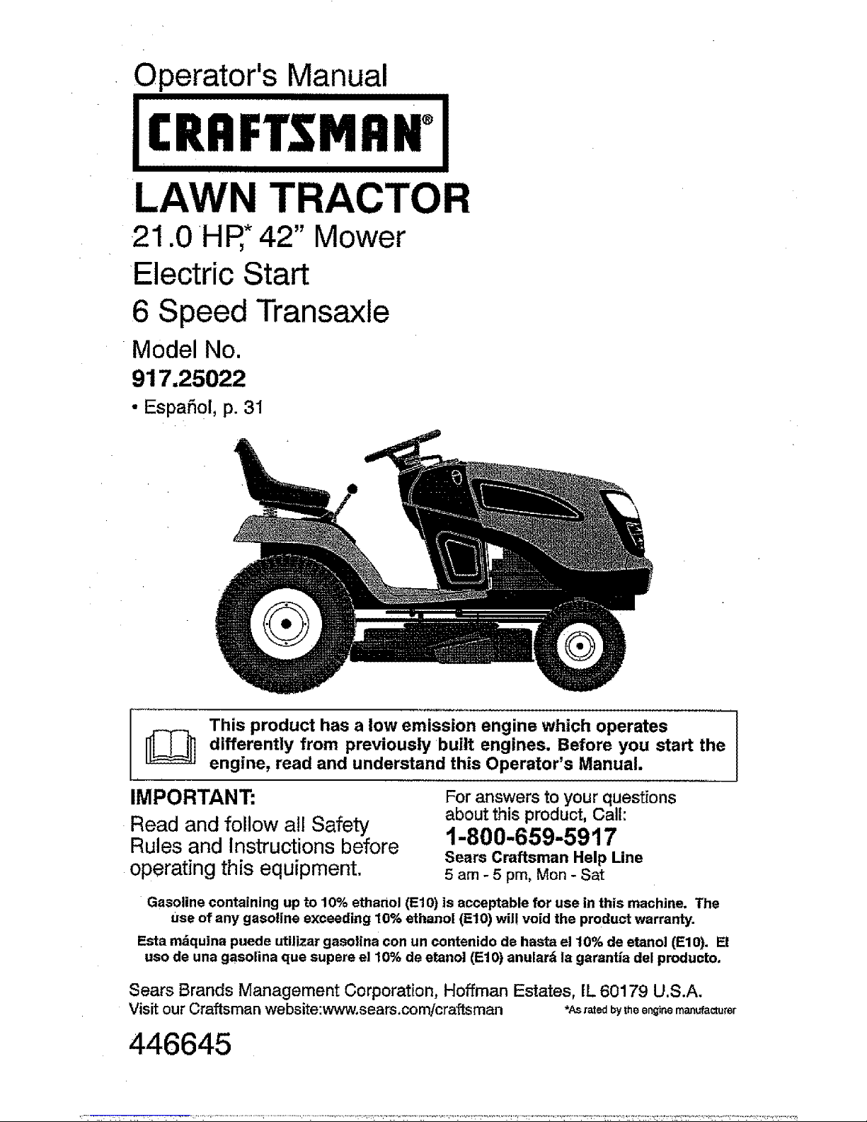
LAWN TRACTOR
21.0 HR*42" Mower
Electric Start
6 Speed Transaxle
Model No.
917.25022
• EspaSol, p. 31
_ This product has a low emission engine which operates
differently from previously built engines, Before you start the
engine, read and understand this Operator's Manual.
IMPORTANT: For answersto yourquestions
Read and follow all Safety about this product, Call:
Rules and Instructions before 1-800-659-5917
Sears Craftsman Help Line
operating this equipment. 5 am - 5 pm, Mon - Sat
Gasoline containing up to 10% ethanol (El0) is acceptable for use in this machine. The
use of any gasoline exceeding 10% ethanol (El0) wil! void the product warranty.
Esta m&quina puede utilizar gasolina con un contenido de haste el 10% de etanol (El0). El
uso de una gasolina qua supere el 10% de etanol (El0) anular6 la garantie del producto,
Sears Brands Management Corporation, Hoffman Estates, IL 60179 U.S.A.
Visit our Craftsman website:www.sears.com/craftsman *As rated bytheenginemanufacturer
446645
Page 2
Warranty .................................................. 2
Safety Rules ............................................ 3
Product Specifications ............................. 6
Assembly/Pre-Operation ......................... 7
Operation ................................................. 9
Maintenance .......................................... 15
Maintenance Schedule .......................... t5
Service and Adjustments ....................... 19
Storage .................................................. 25
Troubleshooting ..................................... 26
Sears Service .......................... Back Cover
Craftsman Riding Equipment Warranty
CRAFTSMAN FULL WARRANTY
FOR TWO YEARS from the date of purchase, all non-expendable parts Ofthis ridingequipment are
warranted against any defects in material or workmanship. A defective non-expendable part will
receive free in-home repair or replacement if repair is impossible.
FOR FIVE YEARS from the date of purchase, the frame and front axle of this riding equipment are
warranted against any defects in material or workmanship. A defective frame or front axle will receive
free in-home repair or replacement if repair is impossible.
FOR 90 DAYS from the date of purchase, the battery (an expendable part) of this riding equipment
is warranted against any defects in material or workmanship (our testing proves that it will not hold a
charge). A defective battery will receive free in-home replacement.
ADDITIONAL LIFETIME LIMITED WARRANTY on CAST IRON FRONT AXLE (if equipped)
FOR AS LONG AS IT IS USED by the original owner after the fifth year from the date of purchase, the
cast iron front axle (ifequipped) ofthis riding equipment iswarranted against any defects in mateda] or
workmanship. With proofof purchase, a defective cast front axle will receive free in-home replacement.
WARRANTY SERVICE
For warranty coverage details to obtain free repair or replacement, call 1-800-659-5917 or visit the
web site: www.craftsman.com
In alI cases above, if part repair or replacement is impossible, the riding equipment wilt be replaced
free of charge with the same or an equivalent model.
All of the above warranty coverage is void if this riding equipment is ever used while providing
commercial services or if rented to another person.
This warrantycovers ONLYdefects in material andworkmanship.Warranty coverage does NOTinclude:
• Expendable parts (except battery) that can wear out from normal use within the warranty period,
including but not limited to blades, spark plugs, air cleaners, belts, and oil filters.
- Standard maintenance servicing, oil changes, or tune-ups.
• Tire replacement or repair caused by punctures from outside objects, such as nails, thorns,
stumps, or glass.
• Tire or wheel replacement or repair resultingfrom normal wear, accident, or improper operation or
maintenance.
° Repairs necessary because of operator abuse, including but not limited to damage caused by
towing objects beyond the capability of the riding equipment, impacting objects that bend the
frame, axle assembly or crankshaft, or over-speeding the engine.
• Repairs necessary because of operator negligence, including but not limited to, electrical and
mechanical damage caused by improper storage, failure to use the proper grade and amount
of engine oil, failure to keep the deck clear of flammable debris, or failure to maintain the riding
equipment according to the instructions contained in the operator's manual.
• Engine (fuel system) cleaning or repairs caused by fuel determined to becontaminated oroxidized
(stale). In general, fuel should be used within 30 days of its purchase date.
• Normal deterioration and wear of the exterior finishes, or product label replacement.
This warranty gives you specific legal rights, and you may also have other rights which vary from
state to state.
Sears Brands Management Corporation, Hoffman Estates, IL 60179
Page 3
_DANGER: This cutting machine is capable of amputating hands and feet and
throwing objects. Failure to observe the following safety instructions could result
in serious injury or death.
_WARNING: Inorder to prevent acciden-
tal starting when setting up, transporting,
adjustingor making repairs, always discon-
nect spark plug wire and place wire where
it cannot contact spark plug.
_kWARNING: Do not coast down a hill in
neutral, you may lose control of the tractor.
_[_WARNING: Tow only the attachments
that are recommended by and comply with
specifications of the manufacturer of your
tractor. Use common sense when towing.
Operate only at the lowest possible speed
when on a slope. Tooheavy of a load,while
on a slope, is dangerous. Tires can lose
traction with the ground and cause you to
lose control of your tractor,
_WARNING: Engine exhaust, some of
its constituents, and certain vehicle compo-
nents contain or emit chemicals known to
the State of California to cause cancer and
birth defects or other reproductive harm,
,_WARNING: Battery posts,terminals and
related accessories contain lead and lead
compounds, chemicals known tothe Stateof
California to cause cancer and birth defects
or other reproductive harm. Wash hands
after handling.
I. GENERAL OPERATION
• Read, understand,and followall instruc-
tions on the machine and in the manual
before starting.
• Do not put hands or feet near rotating
parts or under the machine. Keep clear
ofthe discharge opening at all times.
° Only allow responsible adults, who are
familiar with the instructions, to operate
the machine.
° Clear the area ofobjects such as rocks,
toys, wire, etc., which could be picked
up and thrown by the blades.
° Be sure the area is clear of bystanders
beforeoperating. Stopmachine ifanyone
enters the area,
• Never carry passengers.
• Do not mow in reverse unless absolutely
necessary, Always Iookdown andbehind
before and while backing.
• Never direct discharged materialtoward
anyone. Avoid discharging material
against a wall or obstruction. Material
may ricochet back toward the operator.
Stop the blades when crossing gravel
surfaces.
• Do not operate machine without the en-
tire grass catcher, discharge chute, or
othersafety devices in placeand working.
• Slow down before turning.
• Never leave a running machine unat-
tended. Always turn off blades, set
parking brake, stop engine, and remove
keys before dismounting.
• Disengage blades when not mowing.
Shut off engine and wait for all parts to
cometo a complete stop before cleaning
the machine, removing the grass catcher,
or unclogging the discharge chute.
° Operate machine only indaylight or good
artificial light.
• Do not operate the machine while under
the influence of alcohol or drugs.
• Watch for traffic when operating near or
crossing roadways.
• Useextra carewhen loading orunloading
the machine into atrailer or truck.
• Always wear eye protectionwhen operat-
ing machine.
• Data indicates that operators, age 60
years and above, are involved in a large
percentage of riding mower-related inju-
ries. These operators should evaluate
their ability to operate the riding mower
safely enough to protect themselves and
othersfrom serious injury.
° Followthe manufacturer's recommenda-
tion forwheelweights orcounterweights.
• Keep machine free of grass, leaves or
other debris build-up which cantouch hot
exhaust / engine parts and burn. Do not
allow the mower to plow leaves or other
debris which can cause build-up to oc-
cur. Clean any oil or fuel spillage before
operating or storing the machine. Allow
machine to cool before storage.
8
Page 4
II, SLOPE OPERATION
Slopes are a major factor related to loss of
control and tip-over accidents, which can
result in severe injury or death. Operation
on all slopes requires extra caution. If you
cannot back upthe slopeor ifyoufeel uneasy
on it, do not mow it.
• Mow up and down slopes, not across,
• Watch for holes, ruts, bumps, rocks, or
other hidden objects, Uneven terrain
could overturn the machine. Tall grass
can hide obstacles.
Choose a low ground speed sothat you
will not have to stop or shift while on the
slope.
• Do notmow onwet grass.Tires may lose
traction.
Always keep the machine in gear when
goingdown slopes. Donotshiftto neutral
and coast downhill,
• Avoid starting, stopping, or turning on a
slope, lfthetireslosetraction, disengage
the blades and proceed slowly straight
down the slope,
• Keep all movement on the slopes slow
and gradual. Do not make sudden
changes in speed or direction, which
could cause the machine to roll over.
• Use extra care while operating machine
with grass catchers orother attachments;
they can affect the stability of the ma-
chine, Do no use on steep slopes.
• Do not try to stabilize the machine by
putting your foot on the ground.
• Do not mow near drop-offs, ditches,
or embankments. The machine could
suddenly roll over if a wheel is over the
edge or ifthe edge caves in.
!11.CHILDREN
_WARNING: CHILDREN CAN BE INJURED
BY THIS EQUIPMENT. The American Acade-
my of Pediatrics recommends that children
be a minimum of 12 year of age before op-
erating a pedestrian controlled lawn mower
and a minimum of 16 years of age before
operating a riding lawn mower.
Tragic accidents can occur ifthe operator
is not alert to the presence of children.
Children are often attracted to the machine
and the mowing activity. Never assume
that children will remain where you last
saw them.
4
- Keep children out of the mowing area
and in the watchful care ofa responsible
adult other than the operator.
• Be alert and turn machine off if a child
enters the area.
• Before and while backing, look behind
and down for small children.
• Never carrychildren,even withthe blades
shutoff. They mayfaUoffand beseriously
injured or interfere with safe machine
operation. Children who have beengiven
rides inthe past may suddenly appear in
the mowing area for another ride and be
run overor backed over by themachine.
• Never allow children to operate the ma-
chine,
• Use extra care when approaching blind
corners, shrubs, trees, or other objects
that may block your view of a child,
IV. TOWING
• Tow only with amachine that has ahitch
designed for towing. Do notattach towed
equipment except at the hitch point.
• Followthe manufacturer's recommenda-
tion forweight limits for towed equipment
and towing on slopes.
• Never allow children or others in or on
towed equipment.
• On slopes, theweight ofthe towedequip-
ment may cause loss oftraction and loss
of control.
• Travel slowly and allowextra distance to
stop.
V. SERVICE
SAFE HANDLING OF GASOLINE
To avoid personal injuryor property dam-
age, use extreme care in handling gasoline.
Gasoline is extremely flammable and the
vapors are explosive,
• Extinguish all cigarettes, cigars, pipes,
and other sources of ignition.
• Use only approved gasoline container.
• Never remove gas cap or add fuel with
the engine running. Allow engine to cool
before refueling.
. Never fuel the machine indoors.
• Neverstorethe machine orfue]container
where there is an open flame, spark, or
pilot light such as on a water heater or
other appliances.
• Never fill containers inside a vehicle or
on atruck ortrailer bed with plastic liner.
Always place containers on the ground
away from your vehicle when filling.
Page 5
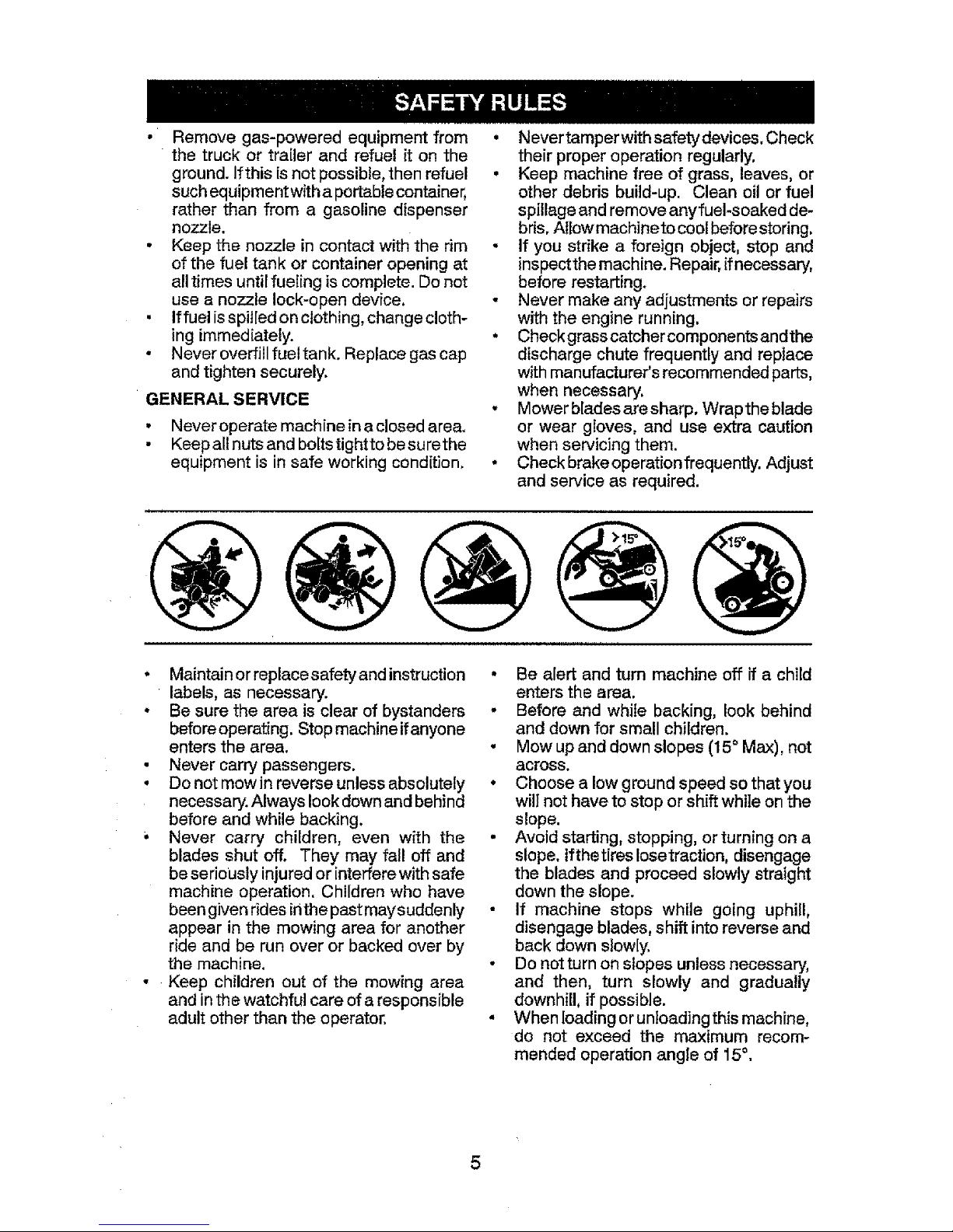
• Removegas-poweredequipmentfrom
thetruckortrailerandrefuelitonthe
ground.Ifthis[snotpossible,thenrefuel
suchequipmentwithaportablecontainer,
ratherthanfromagasolinedispenser
nozzle.
• Keepthenozzleincontactwiththerim
ofthefueltankorcontaineropeningat
alltimesuntilfuelingiscomplete.Donot
useanozzlelock-opendevice.
• iffuelisspilledonclothing,changecloth-
ingimmediately.
• Neveroverfillfueltank.Replacegascap
andtightensecurely.
GENERAL SERVICE
• Never operate machine in a closed area,
• Keep all nuts and boltstightto be surethe
equipment is in safe working condition.
• Never tamperwith safety devices. Check
their proper operation regularly.
• Keep machine free of grass, leaves, or
other debris build-up. Clean oil or fuel
spillage and remove anyfuel-soaked de-
bris, Allow machineto coot beforestoring.
• If you strike a foreign object, stop and
inspectthe machine. Repair,ffnecessary,
before restarting.
• Never make any adjustments or repairs
with the engine running.
• Checkgrass catcher components andthe
discharge chute frequently and replace
with manufacturer's recommended parts,
when necessary.
- Mowerbladesaresharp, Wraptheblade
or wear gloves, and use extra caution
when servicing them.
• Check brakeoperationfrequently. Adjust
and service as required.
, Maintain or replacesafety and instruction
labels, as necessary.
o Be sure the area is clear of bystanders
beforeoperating. Stopmachine ifanyone
enters the area,
• Never carry passengers.
• Do not mow inreverse unless absolutely
necessary.Always look downand behind
before and while backing,
• Never carry children, even with the
blades shut off. They may fall off and
be seriously injured or interfere withsafe
machine operation. Children who have
beengiven rides inthe past maysuddenly
appear in the mowing area for another
ride and be run over or backed over by
the machine.
• Keep children out of the mowing area
and inthe watchful care of aresponsible
adult other than the operator.
• Be alert and turn machine off if a child
enters the area.
° Before and while backing, look behind
and down for small children.
• Mow up and down slopes (15°Max), not
across,
° Choose a low ground speed so that you
will not have to stop or shift while on the
slope.
• Avoid starting, stopping, or turning on a
slope, lfthetires Iosetraction, disengage
the blades and proceed slowly straight
down the slope.
• If machine stops while going uphill,
disengage blades, shift into reverse and
back down slowly.
• Do not turn on slopes unless necessary,
and then, turn slowly and gradually
downhill, if possible.
• When loading orunloading this machine,
do not exceed the maximum recom-
mended operation angle of 15°,
Page 6

PRODUCTSPECIFICATIONS
Gasoline Capacity 2.50 Galtons19,46 L
and type: Regular Unleaded
Oit Type: SAE 30 (above 32°F/0°C)
_PI: SG-SL) SAE 5W30 (below 32°F/0°C
Oil Capacity: WJ Filter: 56 Oz.!1,65 L
W/out Filter: 48 OzJ1,4 L
Spark Plug: Champion RC12YC
(Gap: .030"/0,75 ram)
Ground Speed Forward: 1st t,0/1,6
(Mph/Kph): 2nd 1,4/2,3
3rd 2,1/3,4
4th 3,1/5,1
5_h 4.0/8,4
6th 5.4/8,2
Reverse: 0 - 2.9/4,7
Charging 3 Amps Battery
System: 5 Amps Headlights
Battery: Amp!Hr: 28
Min. CCA: 230
Case size: U1R
Blade Bolt Torque: 45-55 Ft, LbsJ62-75 Nm
CONGRATULATIONS on your purchase of
a new tractor. It has been designed, engi-
neered and manufactured to give you the best
possible dependability and performance.
Should you experience anyproblem you can-
not easily remedy, please contact a Sears or
other qualified service center. We have com-
petent, well-trained representatives and the
proper tools to service or repair this tractor.
Please read and retain this manual. The
instructions will enable you to assemble
and maintain your tractor properly. Always
observe the "SAFETY RULES".
CUSTOMER RESPONSIBILITIES
• Read and observe the safety rules.
o Foliow a regular schedule inmaintaining,
caring for and using your tractor,
• Follow instructions under "Maintenance"
and "Storage" sections of this manual.
° Wear proper Personal Protective Equip-
ment (PPE)while operating this machine,
including (at aminimum) sturdy footwear,
eye protection, and hearing protection.
Do not mow in shorts and/or open toed
footwear.
• Always letsomeone know you are outside
mowing.
_JlLWARNING: This tractor isequipped with
aninternal combustion engine and shouldnot
be used on or near any unimproved forest-
covered, brush-covered or grass-covered
land unless the engine's exhaustsystem is
equipped with a spark arrester meeting ap-
plicable local or state laws (if any). Ifaspark
arrester is used, it should be maintained
in effective working order by the operator.
Inthestate of Ca[ffomiathe aboveis required
bylaw (Section4442 ofthe California Public
Resources Code). Other states may have
similar laws. Federal laws apply onfederal
lands. A spark arrester for the muffler is
availablethrough your nearestSears service
center (See REPAIR PARTS manual).
REPAIR PROTECTION AGREEMENTS
Congratulations on making a smart pur-
chase. Your new Craftsman@ product is
designed and manufactured for years of
dependable operation. But like all products,
itmay require repair from time totime. That's
when having a Repair Protection Agreement
can save you money and aggravation.
Purchase a Repair Protection Agreement
now and protect yourself from unexpected
hassle and expense.
Here's what's included in the Agreement:
• Expertservice byour 12,000 professional
repair specialists.
• Unlimited serviceand no chargefor parts
and labor on all covered repairs.
• Product replacement if your covered
product can't be fixed.
• Discount of 10% from regular price of
service and service-related parts not
covered bythe agreement; also, 10%off
regular priceof preventive maintenance
check.
• Fast help by phone - phone support
from a Sears representative onproducts
requiring in-home repair,plusconvenient
repair scheduling.
Onceyou purchasethe Agreement, asimple
phone calt isall that ittakesfor youto sched-
uleservice. Youcan cattanytime dayor night,
or schedule a service appointment online.
Sears has over 12,000 professionalrepair
specialists, who have access to over 4.5
million quality parts and accessories. That's
the kind ofprofessionalism you cancount on
to help prolong the life ofyour new purchase
for years to come. Purchase your Repair
Protection Agreement today!
Some limitations and exclusions apply.
For pricesand additional information call
1-800-827-6655.
SEARS INSTALLATION SERVICE
For Sears professional installation of home
appliances, garage door openers, water
heaters, and other major home items, inthe
U.S.A, call 1-800-4-MY-HOME@
Page 7
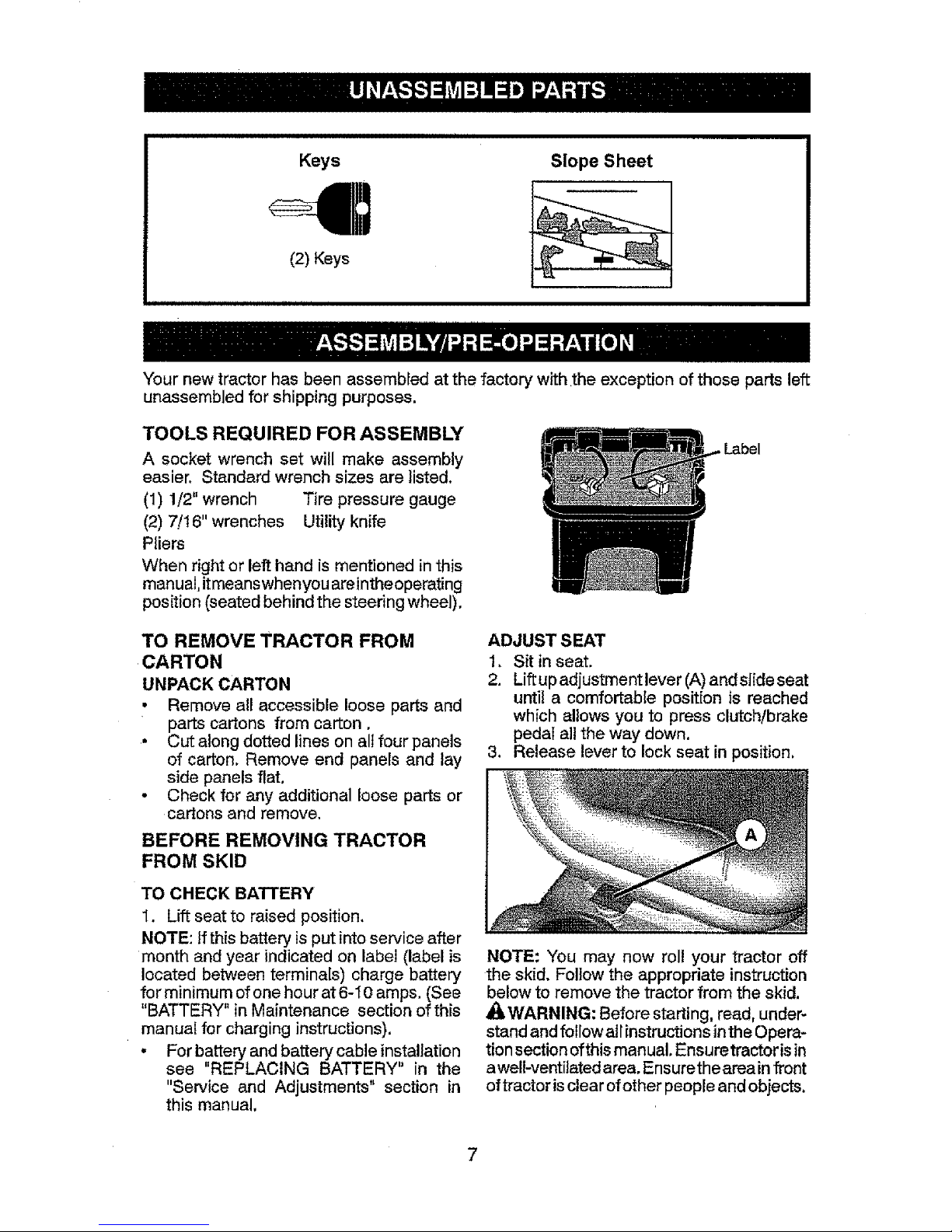
Keys Slope Sheet
(2) Keys
i,iiiL.J.lluJJJlJH ILLuJu,i.JLiii i/i/iLlLI/i H/i/ i1_/ii ill i i
Your new tractorhas been assernbledat the factory with the exception ofthose parts left
unassembled for shipping purposes.
TOOLS REQUIRED FOR ASSEMBLY
A socket wrench set will make assembly
easier. Standard wrench sizes are listed.
(1) 1/2" wrench Tire pressuregauge
(2) 7/t 6" wrenches Utility knife
Pliers
When right or left hand is mentioned in this
manual,itmeanswhenyou areintheoperating
position (seatedbehind the steering wheel).
TO REMOVE TRACTOR FROM
CARTON
UNPACK CARTON
• Remove all accessible loose parts and
parts cartons from carton.
• Cut along dotted lines on all four panels
of carton. Remove end panels and lay
side panels flat.
o Check for any additional loose parts or
cartons and remove,
BEFORE REMOVING TRACTOR
FROM SKID
TO CHECK BATTERY
1. Lift seat to raised position,
NOTE: Ifthis battery is put intoservice after
month and year indicated on label (label is
located between terminals) charge battery
for minimum of onehour at 6-I0 amps. (See
"BATTERY" in Maintenance section of this
manual for charging instructions).
, For battery and battery cable installation
see "REPLACING BATTERY" in the
"Service and Adjustments" section in
this manual.
ADJUST SEAT
1, Sit inseat.
2. Liftupadjustment lever(A)andsiide seat
until a comfortable position is reached
which allows you to press clutch!brake
pedal a]]the way down,
3. Release lever to lock seat in position.
NOTE: You may now roll your tractor off
the skid. Foliow the appropriate instruction
below to remove the tractor from the skid.
Al_WARNING: Before starting, read, under-
stand andfollowall instructions inthe Opera-
tionsection ofthis manual. Ensuretractoris in
awell-ventilatedarea, Ensurethearea infront
oftractor isclear ofother people and objects.
7
Page 8
TO ROLL TRACTOR OFF SKID
(See Operation section for location
and function of controls)
1. Raise attachment liftlever to its highest
position.
2. Release parking brake by depressing
clutch/brake pedal.
3. Place gearshift lever in neutral position.
4. Roll tractor forward off skid.
5. Remove banding holding the deflector
shield up against tractor.
Continue with the instructionsthat follow.
CHECK TIRE PRESSURE
Thetires on yourtractor were overinflated at
the factory for shipping purposes. Correct
tire pressure is important for best cutting
performance.
• Reduce tire pressure to PSI shown on
tires.
CHECK DECK LEVELNESS
For best cutting results, mower housing
should be properly leveled. See"TO LEVEL
MOWER" in the Service and Adjustments
section of this manual.
CHECK FOR PROPER POSITION
OF ALL BELTS
See the figures that are shown for replac-
ing motion and mower blade drive belts in
the Service and Adjustments section of this
manual. Verify that the belts are routed
correctly.
CHECK BRAKE SYSTEM
After you learn how to operate your tractor.
check to see that the brake is operating
properly. See "TO CHECK BRAKE" in the
Service and Adjustments section of this
manual.
t/f LISTA DE REVISION
Antes de operarydedisfrutar desu tractor nuevo,
le deseamos que reciba el mejor rendimiento y [a
mayor satisfaccion de este preducto de calidad.
Haga el favor de revisar ta lista a continuacion;
J Se ban comp]etado todas las instrucciones de
montaje.
vt Noquedan partessueltas enlacaja decart6n.
J La bater{a est&preparadaycargada enforma
adecuada.
I/El asiento ha side ajustado en forma c6moda
y apretado en forma segura.
,/Todas Ias tlantas han side infladas en forma
adecuada. (Para fines de envio, Ias Ilantasse
inflaron demasiado en Ia f&bdca.)
v( Asegt3rese que el conjunto segador est_
nivelado en forma adecuada, de lade a lade
y desde adelante hacia atr&s, para obtener los
mejores resultados en el corte. (Las ]lantas
tienen que estar infladas en forma adecuada
para la nivelaci6n.)
V_ Revise las correas de imputsi6n y de la
segadora. Asegt_rese que recorran el paso
adecuado alrededor de fas poleas y dentro
de lodes los fijadores de las correas.
J Revise el alambrado. Fijese que todas ]as
conexiones todavia est6n seguras y que los
atambres est6n sujetos en forma adecuada.
A1mismo tiempo que aprende a come usar su
tractor, preste atencion extra a los puntos de
importancia que se presentan a continuacion:
V( El aceite deI motor tiene que ilegar at nive]
adecuado.
_" Elestanque decombustible tiene queestarlleno
con gasolina sin pfomo regular,nueva y Iimpia.
_" Familiaricese con todos los controles - su
ubicaci6n y su funci6n. Op6relos antes de
hacer arrancar el motor.
vf Aseg(Jrese9ue el sistema de frenos est_ en
una condicion de operaci6n segura.
_' Asegurarse de que el Sistema de Presencia
del Operador y el Sistema de Funcionamiento
Atr_.s (ROS) funcionan de mode adecuado
(Vet Ias Secciones de Funcionamiento y
Mantenimiento en este manual).
8
Page 9
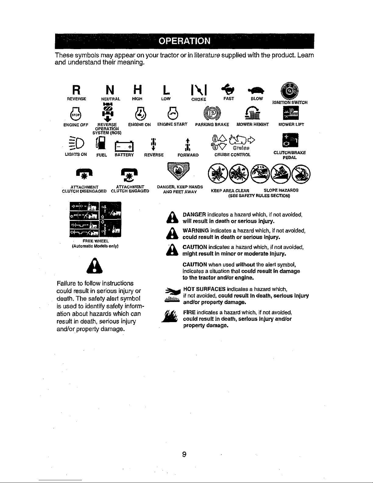
Thesesymbolsmayappearonyourtractororinliteraturesupplied with the product, Learn
and understand their meaning.
R N H L
REVERSE NEUTRAL HIGH LOW
ENGINE OFF REVERSE ENG|NE ON ENGINE START
OPERATION
SYSTEM (ROe)
U GHT,3 ON FUEL BATI'ERY REVERSE FORWARD
ATTACHMENT ATTACHMENT DANGER, KEEP HANDS
CLUTCH DISENGAGED CLUTCH ENGAGED AND FEET AWAY
FREE WHEEL
(Automatic Models only)
Failure to follow instructions
could result in serious injury or
death, The safety alert symbol
is used to identify safety inform-
ation about hazards which can
result in death, serious injury
and/or proper_ damage.
i\!
CHOKE FAST SLOW
PARKING BRAKE MOWER HEIGHT
IGNITION SWITCH
MOWERLIFT
CRUISE CONTROL CLUTCWBRAKE
PEDAL
KEEP AREA CLEAR SLOPE HAZARDS
(SEE SAFETY RULES SECTION}
DANGER indicates a hazard which, if not avoided.
will result in death or serious injury.
WARNING indicates a hazard which, if not avoided,
could result in death or serious injury.
CAUTION indicates a hazard which, if not avoided,
might result in minor or moderate Injury.
CAUTION when used without the alert symbol,
indicates a situation that could result In damage
to the tractor and/or engine.
HOT SURFACES indicates a hazard which,
if not avoided, could result In death, serious Injury
and/or property damage.
FIRE indicates a hazard which, if not avoided.
could result In death, serious injury and/or
proPerty damage.
9
Page 10

KNOW YOUR TRACTOR
READ THIS MANUAL AND SAFETY RULES BEFORE OPERATING YOUR TRACTOR
Compare the illustrations with your tractor to familiarize yourself withthe locations of vari-
ous controls and adjustments. Save this manual for future reference.
03078
Our tractors conform to the applicable safety standards of the
American National Standards Institute,
(A) ATTACHMENT LIFT LEVER - Used to
raise and lower the mower or other attach-
ments mounted to your tractor.
(B) CLUTCH/BRAKE PEDAL -Used for
declutching and braking the tractor and
starting the engine,
(C) PARKING BRAKE - Locksclutch/brake
pedal into the brake position,
(D) THROTTLE/CHOKE CONTROL- Used
for starting and controlling engine speed.
(E) ATTACHMENT CLUTCH LEVER- Used
toengagethe mower blades, or otherattach-
ments mounted to your tractor,
(F) IGNITION SWITCH - Used for starting
and stopping the engine.
(G) REVERSE OPERATION SYSTEM
(ROS) "ON" POSITION -Allows operation
ofmower or other powered attachment while
in reverse.
(H) LIGHT SWITCH - Turns the headlights
on and off,
(J) GEARSHIFT LEVER- Selects the speed
and direction of tractor.
10
Page 11
The operation of anytractor can result inforeign objects thrown into the eyes,t
which can result in severe eye damage. Always wear safety glasses or eye{
shields while operating your tractor or performing any adjustments or repairs.I
We recommend standard safety glasses or a wide vision safety, mask wornl
over spectacles. /
HOW TO USE YOUR TRACTOR
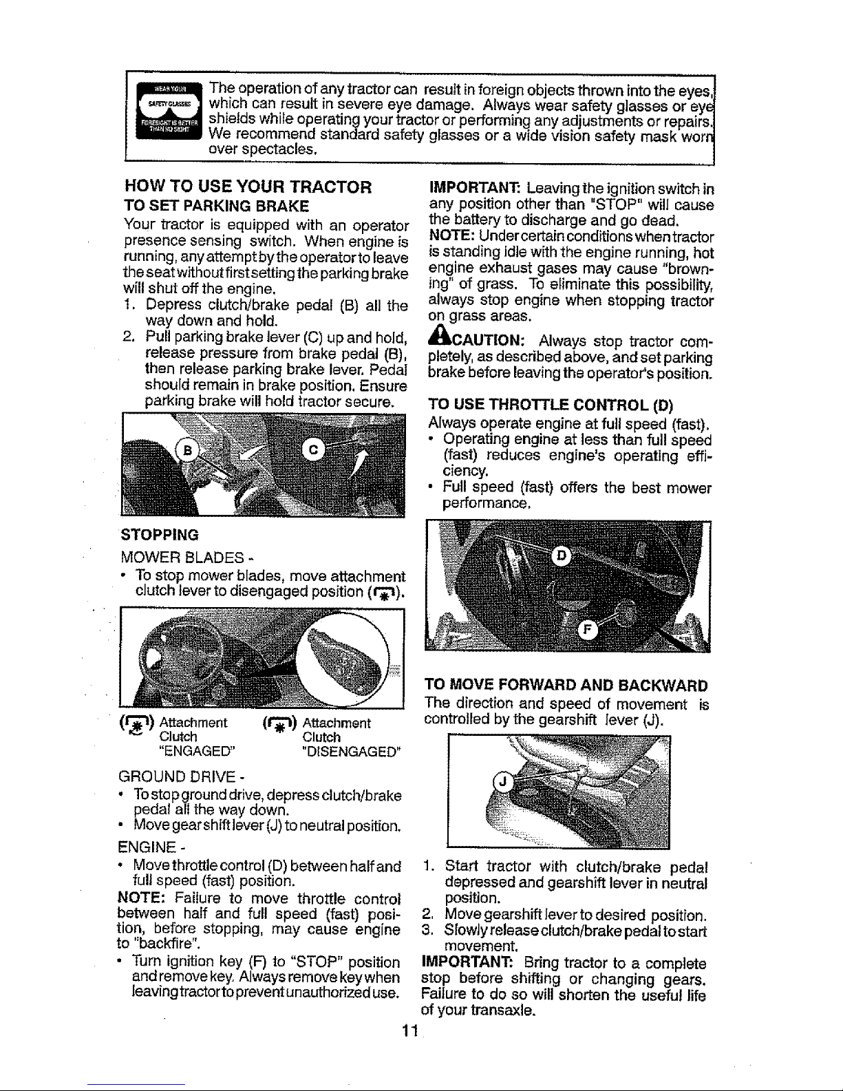
TO SET PARKING BRAKE
Your tractor is equipped with an operator
presence sensing switch. When engine is
running, anyattempt bythe operator toleave
the seat withoutfirst settingthe parking brake
will shut off the engine.
1. Depress clutch/brake pedal (B) all the
way down and hold.
2. Pull parking brake lever (C) up and hold,
release pressure from brake pedal (B),
then release parking brake lever, Pedal
should remain in brake position. Ensure
parking brake will hold tractor secure.
IMPORTANT: Leavingthe ignition switch in
any position other than "STOP" will cause
the battery to discharge and go dead.
NOTE: Undercertain conditionswhen tractor
isstanding idle with the engine running, hot
engine exhaust gases may cause "brown-
ing"of grass. To eliminate this possibility,
always stop engine when stopping tractor
on grass areas.
_CAUTION: Always stop tractor com-
pletely,as described above, and set parking
brake before leavingthe operator's position.
TO USE THROTTLE CONTROL (D)
Always operate engine at full speed (fast).
• Operating engine at less than full speed
(fast) reduces engine's operating effi-
ciency.
• Full speed (fast) offers the best mower
performance.
STOPPING
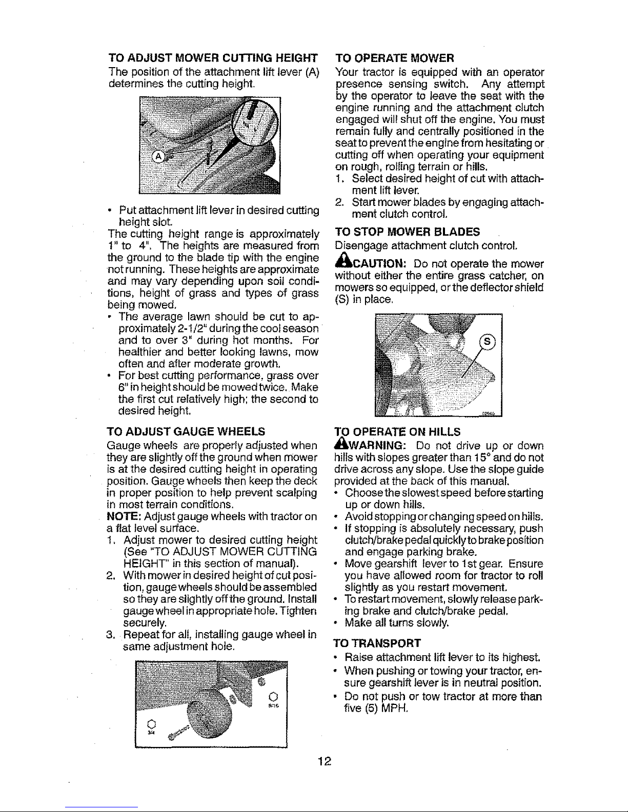
MOWER BLADES -
• Tostop mower blades, move attachment
clutch lever to disengaged position (t_).
(1"_t) Attachment (1_) Attachment
Clutch Clutch
"ENGAGED .... DISENGAGED"
GROUND DRIVE -
• Tostop ground drive, depress clutch!brake
pedal all the way down,
• Move gearshiftlever (J)to neutralposition,
ENGINE -
• Movethrottle control (D) between half and
full speed (fast) position.
NOTE: Failure to move throttle control
between half and full speed (fast) posi-
tion, before stopping, may cause engine
to "backfire",
• Turn ignition key (F) to "STOP" position
and removekey. Always remove keywhen
leavingtractorto preventunauthorized use.
11
TO MOVE FORWARD AND BACKWARD
The direction and speed of movement is
controlledbythe gearshift lever (J).
1. Start tractor with clutch/brake pedal
depressed and gearshift lever inneutral
position.
2, Move gearshift leverto desired position.
3. Slowly release clutch/brake pedalto start
movement,
IMPORTANT: Bring tractor to a complete
stop before shifting or changing gears.
Failure to do so will shorten the useful life
of your transaxle.
Page 12
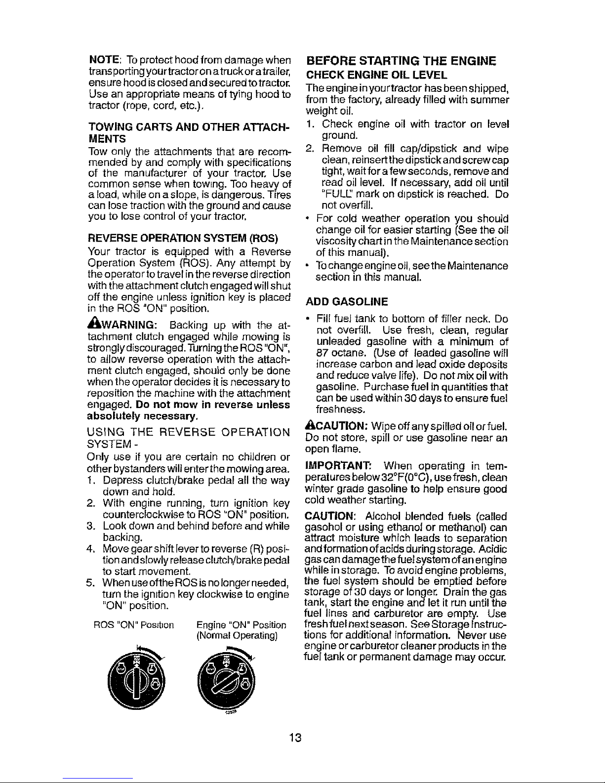
TO ADJUST MOWER CUTTING HEIGHT
The position of the attachment liftlever (A)
determines the cutting height.
• Put attachment lift lever indesired cutting
height slot.
The cutting height range is approximately
1" to 4". The heights are measured from
the ground to the blade tip with the engine
not running. These heights areapproximate
and may vary depending upon soil condi-
tions, height of grass and types of grass
being mowed,
• The average lawn should be cut to ap-
proximately 2-1/2" during the cool season
and to over 3" during hot months. For
healthier and better looking lawns, mow
often and after moderate growth.
• For best cutting performance, grass over
6"in heightshouid bemowedtwice. Make
the first cut relatively high; the second to
desired height.
TO ADJUST GAUGE WHEELS
Gauge wheels are properly adjusted when
they are slightly off the ground when mower
is at the desired cutting height in operating
position. Gauge wheels then keep the deck
in proper position to help prevent scalping
in most terrain conditions.
NOTE; Adjust gauge wheels with tractor on
a flat level surface.
1, Adjust mower to desired cutting height
(See "TO ADJUST MOWER CUTTING
HEIGHT" in this section of manual).
2. With mower in desired height of cut posi-
tion, gaugewheels should beassembled
so they are slightly offthe ground. Install
gauge wheel in appropriate hole. Tighten
securely.
3. Repeat for all, installing gauge wheel in
same adjustment hole.
TO OPERATE MOWER
Your tractor is equipped with an operator
presence sensing switch, Any attempt
by the operator to leave the seat with the
engine running and the attachment clutch
engaged will shut off the engine. You must
remain fully and centrally positioned in the
seat to preventthe engine from hesitating or
cutting off when operating your equipment
on rough, rolling terrain or hills.
1. Select desired height of cut withattach-
ment lift lever.
2. Start mower blades by engaging attach-
ment clutch control.
TO STOP MOWER BLADES
Disengage attachment clutch control.
_kCAUTION: Do not operate the mower
without either the entire grass catcher, on
mowers so equipped, or the deflector shield
(S) in place.
TO OPERATE ON HILLS
,_kWARNING: Do not drive up or down
hills with slopes greater than 15° and do not
drive across anyslope. Use the slope guide
provided at the back of this manual.
° Choose the slowest speed before starting
up or down hills.
• Avoidstopping or changingspeed onhills.
• If stopping is absolutely necessary, push
clutch/brake pedalquicklyto brakeposition
and engage parking brake.
• Move gearshift lever to 1st gear. Ensure
you have allowed room for tractor to roll
slightly as you restart movement.
. Torestart movement, slowly release park-
ing brake and clutch!brake pedal,
• Make all turns slowly.
TO TRANSPORT
• Raise attachment lift lever to its highest.
• When pushing or towing your tractor,en-
sure gearshift lever isin neutral position.
• Do not push or tow tractor at more than
five (5) MPH.
12
Page 13
NOTE: To protect hood from damage when
transporting yourtractor on atruckor atrailer,
ensure hood is closed and secured to tractor.
Use an appropriate means of tying hood to
tractor (rope, cord, etc.).
TOWING CARTS AND OTHER ATTACH-
MENTS
Tow only the attachments that are recom-
mended by and comply with specifications
of the manufacturer of your tractor. Use
common sense when tow=ng. Too heavy of
a load, while on a slope, is dangerous. Tires
can lose traction with the ground and cause
you to lose control of your tractor.
REVERSE OPERATION SYSTEM (ROS)
Your tractor is equipped with a Reverse
Operation System (ROS). Any attempt by
the operator to travel in the reverse direction
with the attachment clutch engaged will shut
off the engine unless ignition key is placed
in the ROS "ON" position.
_kWARNING: Backing up with the at-
tachment clutch engaged while mowing is
strongly discouraged. Turning the ROS "ON",
to allow reverse operation with the attach-
ment clutch engaged, should only be done
when the operator decides it is necessary to
reposition the machine with the attachment
engaged. Do not mow in reverse unless
absolutely necessary.
USING THE REVERSE OPERATION
SYSTEM -
Only use if you are certain no children or
other bystanders will enter the mowing area.
1. Depress clutch/brake pedal all the way
down and hold.
2. With engine running, turn ignition key
counterclockwise to ROS "ON" position.
3. Look down and behind before and while
backing.
4. Movegearshiftleverto reverse (R) posi_
tion and slowly release clutch!brake pedal
to start movement.
5. When useofthe ROS is nolonger needed,
turn the ignition key clockwise to engine
"ON" position.
ROS "ON" PosJt_on Engine "ON" Position
(Normal Operating)
ee
BEFORE STARTING THE ENGINE
CHECK ENGINE OIL LEVEL
The engine inyourtractor has beenshipped,
from the factory, already filled with summer
weight oil.
1. Check engine oil with tractor on level
ground.
2. Remove oil fill cap/dipstick and wipe
clean, reinsert the dipstick and screw cap
tight, wait for afew seconds, remove and
read oil level. If necessary, add oil until
"FULE' mark on dipstick is reached. Do
not overfill.
• For cold weather operation you should
change oil for easier starting (Seethe oi_
viscosity chart inthe Maintenance section
of this manual).
• Tochange engine o11,see the Maintenance
section in this manual.
ADD GASOLINE
• Fill fuel tank to bottom of filler neck. Do
not overfill. Use fresh, clean, regular
unleaded gasoline with a minimum of
87 octane. (Use of leaded gasoline will
increase carbon and lead oxide deposits
and reduce valve life). Do not mix oil with
gasoline. Purchase fuel in quantities that
can be used within 30 days to ensure fuel
freshness.
&CAUTION: Wipe off any spilled oil or fuel.
Do not store, spill or use gasoline near an
open flame.
IMPORTANT: When operating in tem-
peratures below 32°F(00C), usefresh, clean
winter grade gasoline to help ensure good
cold weather starting.
CAUTION: Alcohol blended fuels (called
gasohol or using ethanol or methanol) can
attract moisture which leads to separation
and formation of acids during storage. Acidic
gas can damage the fuel system of an engine
while instorage. To avoid engine problems,
the fuel system should be emptied before
storage of 30 days or longer. Drain the gas
tank, start the engine and let it run until the
fuel lines and carburetor are empty. Use
fresh fuel next season. See Storage Instruc-
tions for additional information. Never use
engine or carburetor cleaner products inthe
fuel tank or permanent damage may occur.
13
Page 14
TO START ENGINE
When starting the engine for the first time or
if the engine has run out of fuel. it will take
extra cranking time to move fuel from the
tank to the engine.
1. Sit on seat in operating position, depress
clutch/brake pedal and set parking brake.
2. Place gear shift lever in neutral position.
3. Move attachment clutch to disengaged
position.
4. Move throttle control to choke position.
NOTE: Before starting, read the warm and
cold starting procedures below.
5, Insert key into Ignition and turn key
clockwise to start position and release
key as soon as engine starts. Do not run
starter contin uously for mo rethan fifteen
seconds per minute. If the engine does
not start after several a_empts, move
throttle control to fast position, wait a
few minutes and try again. If engine still
does not start, move the throttle control
back to the choke position and retry.
WARM WEATHER STARTING
(50 ° F/10 ° C and above)
6. When engine starts, move the throttle
control to the fast position.
• The attachments and ground drive can
now be used. If the engine does not accept
the load, restart the engine and allow itto
warm up for one minute using the choke
as described above,
COLD WEATHER STARTING
(50 _ F/10 ° C and below)
7. When engine starts, reave throttle control
in choke position until engine warms up
and begins to run roughly. Once rough
running begins, immediately move the
throttle control to the fast position. Engine
warm-up may take from several seconds
to several minutes (the colder the tem-
perature, the longer the warm-up).
• The attachments can also be used during
the engine warm-up period,
NOTE: Ifat a high altitude (above 3000 feet)
or in cold temperatures (below 32°F/0°C)
the carburetor fuel mixture may need to be
adjusted for best engine performance (see
"TO ADJUST CARB URETO R" in the Service
and Adjustments section of this manual).
MOWING TIPS
• Tire chains cannot be used when the
mower housing is attached to tractor.
• Mowershould be properly leveledforbest
mowing performance. See "TO LEVEL
MOWER HOUSING" in the Service and
Adjustments section of this manual.
, The left hand side of mower should be
used for trimming,
• Dnve sothat clippings are discharged onto
the area that has already been cut, Have
the cut areato the right of the tractor. This
will result in a more even distribution of
clippings and more uniform cutting.
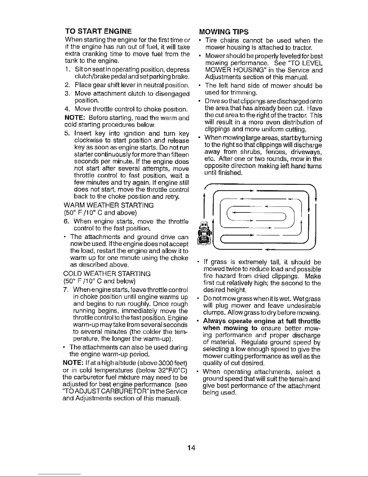
• When mowing large areas, start bytu rning
to the right so that clippings will discharge
away from shrubs, fences, driveways,
etc. After one or two rounds, mow in the
opposite direction making left hand turns
until finished.
f
JJ
J
• If grass is extremely tall, it should be
mowed twice to reduce load and possible
fire hazard from dried clippings. Make
first cut relatively high; the second to the
desired height.
• Do not mow grass when it is wet. Wet grass
will plug mower and leave undesirable
clumps. Allow grass to dry before mowing.
• Always operate engine at full throttle
when mowing to ensure better mow-
ing performance and proper discharge
of material. Regulate ground speed by
selecting a low enough speed to give the
mower cutting performance as well as the
quality of cut desired.
• When operating attachments, select a
ground speed that will suit the terrain and
give best performance of the attachment
being used.
14
Page 15
MAINTENANCE
SCHEDULE
9EFORE
_a_C:H
USE
Check Brake IOpe.ratten
ohe.ok ,e.P....... ,,"
Check Operatar Presence & NON Systems V"
iA Check fe.rLoe.se Fasteners V'
C Ch_cWRe.p[ace Mower B[ade.e
T Lubr=cation Chz, rt
0 Check B_t;e.ry Level
R Clean Batten/andTermma_s
Ore.an Debris Off Steering Plate
Cheek Traes,,axle Ce.e.hng
Check Mowe.r Levelness
Cheek V-Be.Its
i
Check Enqlne O=[ Level
Chz_C.qe. Eni,}ine. O=| (WLth e.zlh_ter)
Chancle En_l_e Od (wFthout o_ filter)
E Clean Air Filter
G Cle.an ALr ScTee.n
| Inspect Muter/SPark Armorer
U' Replr_ce Oil F=lter !If eClu_ppB_ )
E Cl_an En_me Co_ln 9 Fins
Re.p_aee. Spark Plug
Replace Atr Filter Paper C_r_r_d_ie
Rep|a_ce Fur:l Fdter
I_VERY
B
HOURS
EV£RY EVERY EVERY EVERY BEFORE
2_ 50 100 sEASO_ STORAGE
_OURS HQURS HOURS
v',
v'
i| i m If H i|1
v',_ v"
V',, is'
v" . V
Lv',
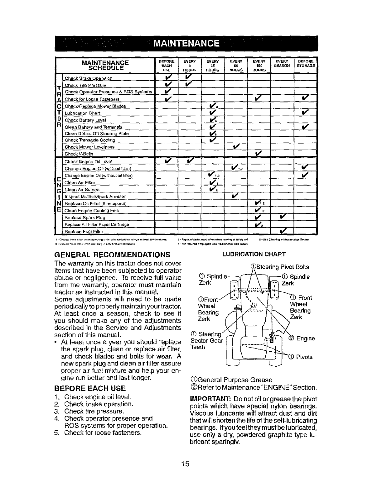
GENERAL RECOMMENDATIONS
The warranty on this tractor does not cover
items that have been subjected to operator
abuse or negligence. To receive full value
from the warranty, operator must ma=ntain
tractor as instructed in this manual
Some adjustments wilt need to be made
pe riodically to properly maintain your tractor.
At [east once a season, check to see if
you should make any of the adjustments
described in the Service and Adjustments
section of this manual.
• At least once a year you should replace
the spark plug, clean or replace air filter,
and check blades and belts for wear. A
new spark plug and clean air filter assure
proper a=r-fuel mixture and help your en-
gine run better and last longer.
BEFORE EACH USE
1. Check engine oil level.
2. Check brake operation.
3, Check tire pressure.
4. Check operator presence and
ROS systems for proper operation.
5. Check for loose fasteners.
LUBRICATION CHART
(f_)SteeringPivot Botts
Spindie__l_--_ Spindle
(_Front! _Lc2__ %; \ I _ _ Front
__;: X_ Wheel
Wheet 4;
_- ....._ Bearing
Bearing
_erk
Zerk /(_
(1).Steering"
Sector Gear I I Engine
Teeth _ Pivots
OGeneral Purpose Grease
@Refer to Maintenance"ENGINE" Section.
IMPORTANT: Do net oilor grease the pivot
points which have special nylon bearings.
Viscous lubricants will attract dust and dirt
thatwill shorten the lifeofthe self-lubricating
bearings. Ifyou feel they must be lubricated,
use only a dry, powdered graphite type lu-
bricant sparingly.
15
Page 16
TRACTOR
Alwaysobservesafetyruleswhenperform-
inganymaintenance.
BRAKE OPERATION
If tractor requires more than five (5) feet to
stop at highest speed in htghest gear on a
level, dry concrete or paved surface, then
brake must be serviced. (See "TO CHECK
BRAKE" in the Service and Adjustments
section of this manual).
TIRES
• Maintain proper air pressure in all tires
(See PSI on tires).
• Keep tires free of gasoline, oil, or insect
control chemicals which can harm rubber.
• Avoid stumps, stones, deep ruts, sharp
objects and other hazards that may cause
tire damage.
NOTE: To seal tire punctures and prevent
flat tires due to slow Ieaks, tire sealant may
be purchased from your local parts dealer.
Tire sealant also prevents tire dry rot and
corrosion.
OPERATOR PRESENCE SYSTEM AND
REVERSE OPERATION SYSTEM (ROS)
Ensure operator presence and reverse
operation systems are workmg properly. If
your tractor does not function as described,
repair the problem immediately.
• The engine should not start unless the
brake pedal is fully depressed, and the
attachment clutch control is in the disen-
gaged position.
CHECK OPERATOR PRESENCE SYSTEM
• When the engine is running, any attempt
by the operator to leave the seat without
first setting the parking brake should shut
off the engine.
• When the engine Is running and the at-
tachment clutch is engaged, any attempt
by the operator to leave the seat should
shut off the engine.
• The attachmentclutch should neveroper-
ate unless the operator is in the seat.
ROS "ON" Position Engine "ON" Position
(Normal Operating)
CHECK REVERSE OPERATION (ROS) SYSTEM
• Whenthe engine is running with the ignition
switch in the engine "ON" position and the
attachment clutch engaged, any attempt
by the operator to drive in reverse should
shut offthe engine.
• When the engineis running withtheignition
switch in the ROS "ON" position and the
attachment clutch engaged, any attempt
by the operator to drive in reverse should
NOT shut off the engine.
BLADE CARE
For best results mower blades must be sharp.
Replace worn, bent or damaged blades.
_kCAUTION: Use only a replacement blade
approved bythe manufacturer ofyourtractor.
Using a blade not approved by the manu-
facturer of your tractor is hazardous, could
damage your tractor and void your warranty.
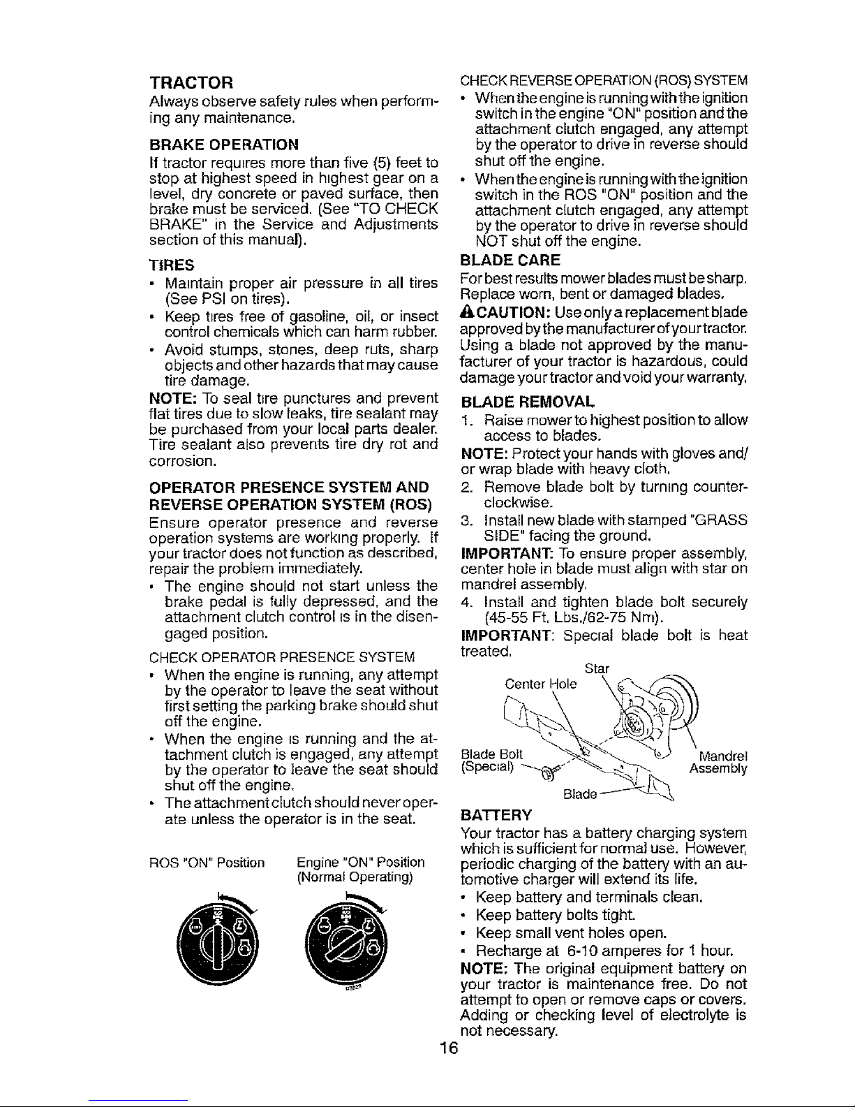
BLADE REMOVAL
I. Raise mowerto highest positionto allow
access to blades.
NOTE: Protect your hands with gloves and/
or wrap blade with heavy cloth,
2. Remove blade bolt by turning counter-
clockwise.
3. Install newblade with stamped "GRASS
SIDE" facing the ground.
IMPORTANT: To ensure proper assembly,
center hole in blade must align with star on
mandrel assembly,
4. Install and tighten blade bolt securely
(45-55 Ft, Lbs.!62-75 Nm).
IMPORTANT; Special blade bolt is heat
treated,
Star
Center Hole
\
Blade Bolt Mandrel
(Special) "_'" Assembly
BA'f-I'ERY
Your tractor has a battery charging system
which is sufficient for normal use. However,
periodic charging of the battery with an au-
tomotive charger will extend its life.
• Keep battery and terminals clean.
• Keep battery bolts tight.
• Keep small vent holes open.
• Recharge at 6-10 amperes for 1 hour.
NOTE: The original equipment battery on
your tractor is maintenance free. Do not
attempt to open or remove caps or covers.
Adding or checking level of electrolyte is
not necessary.
16
Page 17
TOCLEANBATTERYANDTERMINALS
Corrosionanddirtonthebatteryandterminals
cancausethebatteryto"leak" power.
1. Disconnect BLACK battery cable first
then RED battery cable and remove
battery from tractor.
2. Rinse the battery with plain water and dry.
3. Clean terminals and battery cable ends
with wire brush until bright.
4. Coat terminals w{th grease or petro{eum
jelly.
5. Reinstall battery (See "REPLACING
BATTERY" in the SERVICE AND AD-
JUSTMENTS section of this manual).
TRANSAXLE MAINTENANCE
Keep transaxte free from build-up of dirt and
chaff which can restrict cooling.
Do not attempt to clean transaxle while
engine is running or while the transaxle is
hot. To prevent possible damage to seals,
do not use high pressure water or steam to
clean transaxle.
V-BELTS
Check V-belts for deterioration and wear after
100 hours of operation and replace if neces-
sary. The belts are not adjustable. Replace
belts if they begin to slip from wear.
ENGINE
LUB RICATION
Only use high quality detergent oil rated with
AP[ service classification SG-SL. Selectthe
oil's SAE viscosity grade according to your
expected operating temperature.
£AE V_SCOSR'Y GRADES
NOTE: Although multi-viscosityoils (5W30,
] 0W30 etc.) improve starting in cold weather,
they will result in increased oil consumption
when used above 32°F/0°C. Check your
engine oil level more frequently to avoid pos-
sible engine damage from running low on oil
Change the oil after every 50 hours of opera-
tion or at {east once a year if the tractor is
not used for 50 hours in one year,
Check the crankcase oil level before starting
the engine and after each eight (8) hours
of operation. Tighten oil fill cap[dipstick
securely each time you check the oil level.
TO CHANGE ENGINE OIL
Determine temperature range expected
before oil change. All oil must meet API
service classLfication SG-SL.
• Be sure tractor is on level surface.
17
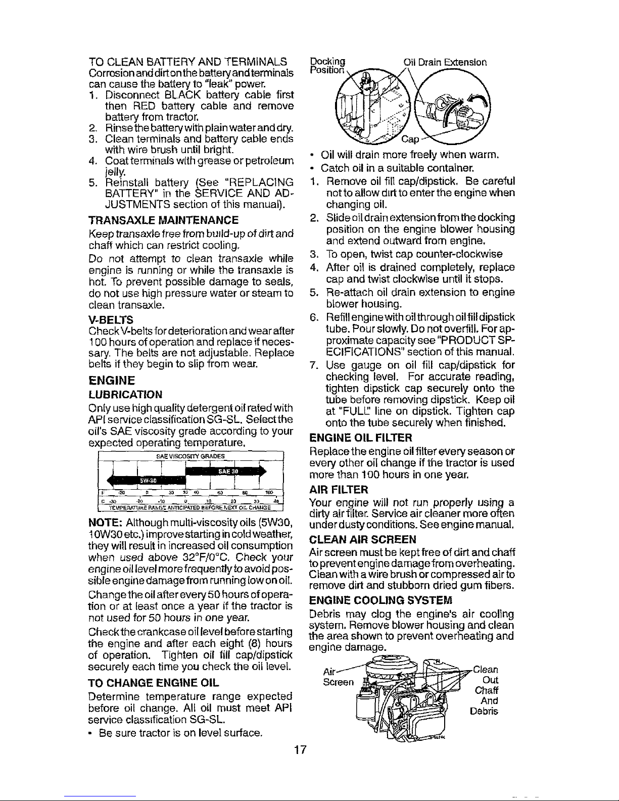
Docking Oil Drain Extension
• Oil will drain more freely when warm.
* Catch oil in a suitable container.
1. Remove oil ill] capldipstick, Be careful
not to allow dirt to enter the engine when
changing oil.
2. Stide oil drain extension from the docking
position on the engine blower housing
and extend outward from engine,
3, To open, twist cap counter-clockwise
4. After oil is drained completely, replace
cap and twist clockwise until it stops.
5. Re-attach oil drain extension to engine
blower housing.
6, Reffil enginewith oil through oilfill dipstick
tube. Pour slowly, Do not overfill, For ap-
proximate capacity see "PRODUCT SP-
ECIFICATIONS" section of this manual.
7. Use gauge on oil fill cap/dipstick for
checking level. For accurate reading,
tighten dipstick cap securely onto the
tube before removing dipstick. Keep oil
at "FULL_ line on dipstick. Tighten cap
onto the tube securely when finished.
ENGINE OIL FILTER
Replace the engine oil filter every season or
every other oil change if the tractor is used
more than 100 hours in one year.
AIR FILTER
Your engine will not run properly using a
dirty air filter. Service air cleaner more often
under dusty conditions. See engine manual.
CLEAN AIR SCREEN
Air screen must be kept free of dirt and chaff
to prevent engine damagefrom overheating.
Clean with a wire brush or compressed air to
remove dirt and stubborn dried gum fibers.
ENGINE COOLING SYSTEM
Debris may clog the engine's air cooling
system. Remove blower housing and clean
the area shown to prevent overheating and
engine damage.
Air--Clean
/_ Debris
Page 18
MUFFLER
Inspect and replace corroded muffler and
spark arrester (if equipped) as itcould create
a fire hazard and/or damage.
SPARK PLUG(S)
Replace spark plug(s) at the beginning of
each mowing season or after every 100
hours of operation, whichever occurs first.
Spark plug type and gap setting are shown
in "PRODUCT SPECIFICATIONS" section
of this manual.
IN-LINE FUEL FILTER
The fuel filter should be replaced once each
season, If fuel filter becomes clogged, ob-
structing fuel flow to carburetor, replacement
is required.
1. With engine cool, remove filter and plug
fuel line sections.
2. Place newfuel filter in position in fuel line
with arrow pointing towards carburetor.
3. Ensure there are no fuel line leaks and
clamps are properly positioned.
4. Immediatelywipe up any spilled gasohne.
amp
CLEANING
• Clean engine, battery, seat, finish, etc,
of all foreign matter.
• Clean debrisfromsteering plate. Debris
can restrictclutch!brake pedal shaft move-
ment, causing belt slip and loss of drive.
/i, CAUTION: Avoid all pinch points and
movable parts
_- _. Clutch/brake pedal
4/ ."
f,' Clean _o_+
I/ topside _ ._//-."
Steerlngplate_,.-;" "_ ....
Steering System, Dash,
Fender and Mower Not Shown
/i"" ¢
CAUTION: I
Pinch I
41_ Points I
• Keep finished surfaces and wheels free
of all gasohne, oil, etc.
• Protect painted surfaces with automotive
type wax.
We do not recommend using a garden hose
or pressure washer to clean your tractor
unless the engine and transmission are
covered to keep water out. Water in engine
or transmission will shorten the useful life of
your tractor. Use compressed air or a leaf
blower to remove grass, leaves and trash
from tractor and mower.
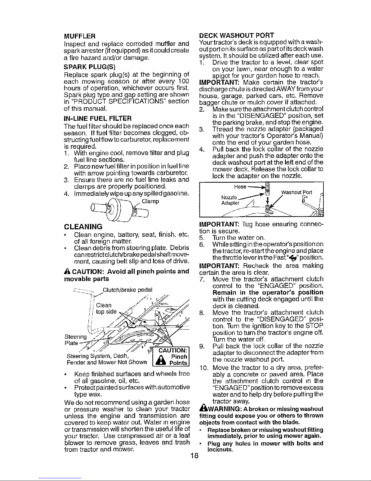
DECK WASHOUT PORT
Your tractor's deck is equipped with a wash-
out port o nits surface as part of its deck wash
system. It should be utilized after each use.
1. Drive the tractor to a level, clear spot
on your fawn, near enough to a water
spigot for your garden hose to reach.
IMPORTANT: Make certain the tractor's
discharge chute is directed AWAY from your
house, garage, parked cars, etc. Remove
bagger chute or mulch cover if attached.
2. Make surethe attachment clutch control
is in the "DISENGAGED" position, set
the parking brake, and stop the engine.
3. Thread the nozzle adapter (packaged
with your tractor's Operator's Manual)
onto the end of your garden hose.
4. Pull back the lock collar of the nozzle
adapter and push the adapter onto the
deck washout port at the left end of the
mower deck. Release the lock collar to
lock the adapter on the nozzle.
Hose_ /
_._._ WashoutPort 4-1
Nozzlo/_ "i / r_ _1
IMPORTANT: Tug hose ensuring connec-
tion is secure.
5. Turn the water on.
6. While sitting inthe operator's position on
the tractor, re-start the engine and place
thethrottle lever in the Fast",_" position.
IMPORTANT: Recheck the area making
certain the area is clear.
7, Move the tractor's attachment clutch
control to the "ENGAGED" position.
Remain in the operator's position
with the cutting deck engaged until the
deck is cleaned.
8. Move the tractor's attachment clutch
control to the "DISENGAGED" posi-
tion. Turn the ignition key to the STOP
position to turn the tractor's engine off.
Turn the water off.
9. Pull back the lock collar of the nozzle
adapter to disconnect the adapter from
the nozzle washout port.
10. Move the tractor to a dry area, prefer-
ably a concrete or paved area. Place
the attachment clutch control _n the
"ENGAGED" position to remove excess
water and to help dry before putting the
_ll tractor away.
WARNING: A broken or missing washout
fitting could expose you or others to thrown
objects from contact with the blade.
• Replace broken or missing washout fitting
immediately, prior to using mower again.
* Plug any holes in mower with bolts and
Iockn uts.
18
Page 19

WARNING: TO AVOID SERIOUS INJURY, BEFORE PERFORMING ANYSERVICE OR ADJUSTMENTS:
1. Depress clutch/brake pedal fully and set parking brake.
2. Place gearshift lever in neutral position,
3. Place attachment clutch in "DISENGAGED" position.
4. Turnignitionkey to "STOP" and remove key.
5. Ensure the blades and all moving parts have completely stopped,
6. Disconnect spark plug wire from spark plug and place wire where it cannot
come in contact with plug.
TO REMOVE MOWER
1, Place attachment clutch in "DISEN-
GAGED" position.
2, Lower attachment lift lever to its lowest
position.
3. Roll belt off engine pulley (M) and belt
keepers ((3).
4. Remove retainer spring (K), slide collar
(L) off and push housing guide (P) out
of bracket.
5. Remove clutch cable spring (Q) from
idler arm (R).
6. Disconnect front link (E) from mower -
remove retainer spring and washer.
7. Go to either side of mower and discon-
nect mower suspension arm (A) from
chassis pin (B) and rear lift link (C) from
rear mower bracket (D) -remove retainer
springs and washers,
A_kCAUTION: After rear lift links are discon-
nected, the attachment li_ leverwill be spring
loaded. Have a tight grip on lift lever when
changing position of the lever,
8. Slide mower outfrom underrights!de of
tractor.
IMPORTANT: If an attachment other than
the mower is to be mounted on the tractor,
remove the front link (E) and rear lift links
(C) from tractor and hook the clutch spring
(Q) into the cable guide on front edge of
lower dash.
TO INSTALL MOWER
Ensure tractor ison level surface and engage
parking brake.
I. Lower attachment lift lever to its lowest
position.
CAUTION: Lift lever is spring loaded.
Have a tight grip on lift lever, lower it slowly
and engage in lowest position.
NOTE: Ensure mower side suspension arms
(A) are pointing forward before sliding mower
under tractor,
2. Slide mower under tractor until it is cen-
tered under tractor.
03042te×
19
Page 20

3. ATTACH MOWER SIDE SUSPENSION
ARMS (A) TO CHASSIS - Position hole
in arm over pin (B) on outside of tractor
chassis and secure with retainer spring.
4. Repeat on opposite side of tractor.
5. ATTACH REAR LIFT LINKS (C) - Lift
rear corner of mower and position slot
in link assembly over pin (D) on rear
mower bracket and secure with washer
and retainer spring.
7. Insert end of link (E) into hole in front
mower bracket (H) and secure with
washer and retainer spnng (J).
8. Hook end of clutch cable spring (Q) into
hole in idler arm (R).
9. Push clutch cable houstng guide (P) into
bracket, slide collar (L) onto guide and
secure with retainer spnng (K).
t0. install belt onto engine pulley (M) and belt
keepers (G).
6. ATTACH FRONT LINK (E) - Work from
left side of tractor. Insert rod end of link
assembly through front hole in tractor
front suspension bracket (F).
IMPORTANT: Check belt for proper routing
tn all mower pulley grooves.
11. Raise attachment lift lever to htghest
position.
12. Ifnecessary, adjus_ gauge wheels before
operating mower as shown in the Opera-
tion section of this manual.
03042[ex
2O
Page 21

TO LEVEL MOWER
Make sure tires are properly inflated to the
PSI shown ontires. If tires are over or under
inflated, it may affect the appearance of your
lawn and lead you to think the mower is not
adjusted properly.
VISUAL SIDE-TO-SIDE ADJUSTMENT
1. With all tires properly inflated and if your
lawn appears unevenly cut, determine
which side of mower is cutting lower.
2. With a 3/4" or adjustable wrench, turn lift
link adjustment nut (A) to the left to lower
LH side of mower, or, to the right to raise
LH side of mower.
NOTE: Each full turn of adjustment nut wilt
change mower height about 3/16".
Turn nut ri Turn nut left
to raise mower to lower mower
3. Test your adjustment by mowing some
uncut grass and visually checking the
appearance. Readjust, ifnecessary, until
you are satisfied with the results.
PRECISION SIDE-TO-SIDE ADJ USTMENT
1. With all tires properly inflated, park tractor
on level ground or driveway.
CAUTION: Blades are sharp. Protect
your hands with gloves and/or wrap blade
with heavy cloth.
2. Raise mower to its highest position.
3. At both sides of mower, position blade at
side and measure the distance (A) from
bottom edge of blade to the ground. The
distance should be the same on both
sides.
4. If adjustment is necessary, see step 2 in
V_sual Adjustment instructions above.
5. Recheck measurements, adjust if neces-
sary until both sides are equal.
At
21
FRONT-TO-BACK ADJUSTMENT
IMPORTANT: Deck must be level side-
to-side.
To obtain the best cutting results, the mower
blades should be adjusted so the front tip is
1/8" to 1/2" lower than the rear tip when the
,_ower is in its highest position.
CAUTION: Blades are sharp. Protect
your hands with gloves and/or wrap btade
with heavy cloth.
• Raise mower to highest position.
• Position any blade so the tip is pointing
straight forward, Measure distance (13)
to the ground at front and rear tip of the
blade.
• If front tip of blade is not 1/8" to 1/2" lower
than the rear tip, go to the front of tractor.
• With an 11/16" or adjustable wrench,
loosen jam nut A several turns to clear
adjustment nut B.
• With a 3/4" or adjustable wrench, turn
front link adjustment nut (B) clockwise
(tighten) to raise the front of mower, or,
counterclockwise (loosen) to lower the
front mower.
Tighten adjust nut Loosen adjust
B to raise mower nut B to lower
mowel"
Loosen jam nut A first
NOTE: Each full turn of the adjustment nut
willchange mower height about 1/8%
• Recheck measurements, adjust ifneces-
sary until front tip of blade is 1/8" to t/2"
bowerthan the rear tip.
• Holdadjustment nutin positionwith wrench
and tighten jam nut securely against ad-
justment nut.
Page 22

TO REPLACE MOWER BLADE DRIVE
BELT
The mower blade drive belt may be replaced
without tools, Park the tractor on level sur-
face. Engage parking brake.
BELT REMOVAL -
1. Remove mower from tractor (See "TO
REMOVE MOWER" in this section of
manuat).
2. Work belt off both mandrel pulleys and
idler pulleys.
3. Pull belt away from mower.
BELT tNSTALLATIO N -
1. Work belt around both mandrel pulleys
and idler pulleys
2. Ensure belt is in all pulley grooves and
inside all belt guides.
3. Install mower (See "To Instal] Mower" in
this section of this manual).
Idler
Pulleys
Mandrel
,Pulley
TO REPLACE MOTION DRIVE BELT
Park the tractor on level su#ace. Engage
parking brake. For assistance, there is a
belt installation guide decal on bottom side
of left footrest,
BELT REMOVAL -
1. Remove mower (See "TO REMOVE
MOWER" in this section of manual).
NOTE: Observe entire motion drive belt
and position of all belt guides and keepers.
2. Remove beltfrom stationary idler (A) and
clutching idler (B).
3. Pull belt slack toward rear of tractor.
Remove belt upwards from transaxle
input pulley (D).
4. Remove belt downward from engine
pulley (E).
5. Slide belt toward rear of tractor, off the
steering plate (F) and remove from tractor.
TO CHECK BRAKE
If tractor requires more than five (5) feet to
stop at highest speed in highest gear on a
level, dry concrete or paved surface, then
brake must be serviced.
You may also check brake by:
1. Park tractor on a Jevel, dry concrete or
paved surface, depress clutch/brake
pedal all the way down and engage
parking brake,
2, Place gear shift lever in neutral position.
The rear wheels must lock and skid when
you try to man ualiy pus h the tractor forward.
If the rear wheels rotate, then the brake
needs to be serviced. Contact a Sears or
other qualified service center.
BELT INSTALLATION -
1. Install new belt from tractor rear to front,
over the steering plate (F) and above
clutch brake pedal shaft (G).
2, Pull belt toward front of tractor and roll
belt onto engine pulley (E).
3. Pull belt toward rear of tractor. Carefully
work bell down around transaxle input
pulley (D). Ensure belt is inside the belt
keeper.
4. Install belt through stationary idler {A)
and clutching idler (B).
5. Ensure belt is in all pulley grooves and
inside all belt guides and keepers.
6. Install mower (See "TO INSTALL MOW-
ER" in this section of manual).
22
Page 23

TRANSAXLE GEAR SHIFT LEVER NEU-
TRAL ADJUSTMENT
The transaxle should be in neutral when the
gear shift lever is in neutral (N) (lock gate)
position. The adjustment is preset at the
factory; however, if adjustment is needed,
proceed as follows:
1. Ensure transaxle is in neutral (N).
NOTE: When the tractor rear wheels move
freely, the transaxle is in neutral.
2. Loosen adjustment bolt in front of the
right rear wheeL.
3. Position the gear shift lever in the neutral
(N) position.
4. Tighten adjustment bolt securely.
NOTE: If additional clearance is needed to
get to adjustment bo]t, move mower deck
height to the lowest position.
Gearshift Lever
Neutral
Lock
Adjustment Bolt Gate
TO REMOVE WHEEL FOR REPAIRS
1. Block up axle securely.
2. Remove axle cover, retaining ring and
washers to allow wheel removal (rear
wheels have a square key - Do net lose).
3. Repair tire and reassemble.
NOTE: On rearwheels only: align grooves in
rearwheel hub and axle. Insert square key.
4. Replace washers and snap retaining ring
securely in axle groove.
5. Replace axle cover.
NOTE: To seal tire punctures and prevent
flat tires due to slow leaks, purchase and
use tire sealant from Sears. Tire sealant also
prevents tire dry rot and corrosion.
Retaining
#
AxleCover "_8qu;_re Key (Rear
Wheel On]y)
FRONT WHEEL TOE-IN/CAMBER
Your new tractor front wheel toe-in and
camber is set at the factory and isnormal,
The front wheel toe-in and camber are not
adjustable. If damage has occurred to
affect the factory set front wheel toe-in or
camber, contact a Sears or other qualified
service center.
TO START ENGINE WITH A WEAK BAT-
"FIERY
_WARNING: Lead-acid batteries gener-
ate explosive gases. Keep sparks, flame
and smoking materials away from batteries.
Always wear eye protection when around
batteries.
Ifyour battery istoo weak to start the engine,
it should be recharged. (See "BATTERY" in
the MAINTENANCE section ofthis manual).
If "jumper cables" are used for emergency
starting, follow this procedure:
IMPORTANT: Your tractor is equipped with
a 12volt system. The other vehicle must also
be a 12 volt system. Do not use your tractor
battery to start other vehicles.
TO ATTACH JUMPER CABLES -
1. Connectoneend ofthe RED cabletothe
POSITIVE (+) terminal of each battery(A-
B), taking care notto short againsttractor
chassis.
2. Connect one end of the BLACK cable
to the NEGATIVE (-) terminal (C) of fully
charged battery.
3. Connect the other end of the BLACK
cable (D) to good chassis ground, away
from fuel tank and battery.
TO REMOVECABLES, REVERSEORDER-
1. BLACK cabIe first from chassis and then
from the fully charged battery.
2. RED cable last from both batteries,
Weak or Dead Fully Charged
Battery Battery
23
Page 24

REPLACING BA'I-I'ERY
n_asWARNING: Do not short battery termi-
by altowi nga wrench or any other object
to contact both terminals at the same time.
Before connecting battery, remove metal
bracelets, wristwatch bands, rings, etc.
Positive terminal must be connected first to
prevent sparking from accidental grounding.
1. Lift seat pan to raised position.
2. Remove terminal cover,
3, Disconnect BLACK battery cable then
RED battery cable and carefully remove
battery from tractor,
4. Install new battery with termtnals _nsame
position as old battery.
5. Reinstall terminal cover.
6. First connect RED battery cable to posi-
tive (+) battery terminal wtth bolt and nut
as shown, Tighten securely.
7. Connect BLACK grounding cable to
negative (-) batteryterminal with remain-
ing bolt and nut. Tighten securely
8. Lower seat pan.
Terminal
Ceverx Negative
(Black)
Nut
Bolt
Positive
(Red)
TO REPLACE FUSE
Replace with30 amp automotive-type plug-
in fuse, The fuse holder is located behind
the dash.
TO REMOVE HOOD AND GRILL
ASSEMBLY
1. Raise hood.
2. Unsnap headlight wire connector.
3. Stand in front of tractor. Grasp hood at
sides, tilt toward engine and lift off of
tractor.
4. When replacing hood, ensure to recon-
nect the headlight wire connector.
Headlight Wire
Connector
ENGINE
TO ADJUST THROTI-LE CONTROL
CABLE
The throttle control has been preset at
the factory and adjustment should not be
necessary Check adjustment as described
below before loosening cable. Ifadjustment
is necessary, see engine manual.
TO REPLACE HEADLIGHT BULB
1. Raise hood.
2. Remove bulb holder from the hole in the
backstde of the grill.
3. Replace bulb m holder and install bulb
holder securely back into the hole in the
backside of the grill.
4. Close hood.
INTERLOCKS AND RELAYS
Loose or damaged wiring may cause your
tractor to run poorly, stop running, or prevent
it from starting.
• Check wiring.
TO ADJUST CHOKE CONTROL
The choke control has been preset at
the factory and adjustment should not be
necessary. If adjustment is necessary, see
engine manual.
TO ADJUST CARBURETOR
You r carburetor has been preset at the factory
and adjustment should not be necessary.
However, m=nor adjustment may be required
to compensate for differences in fuel, tem-
perature, altitude or load. If the enginedoes
need adjustment, see engine manual.
24
Page 25

immediatelyprepareyourtractorforstorage
attheendoftheseasonorifthetractorwill
notbeusedfor30daysormore.
A_, WARNING: Never store the tractor with
gasoline in the tank inside a building where
fumes may reach an open flame or spark.
Allow the engine to cool before storing in
any enclosure,
TRACTO R
Remove mower from tractor for winter stor-
age. When moweristo bestored foraperiod
of time, clean it thoroughly, remove all dirt,
grease, leaves, etc. Store in aclean, dry area.
1, Clean entire tractor (See"CLEANING" in
the Maintenance section of this manuaf).
2. Inspect and replace belts, ff necessary
(See belt replacement instructions in the
Service and Adjustments section of this
manual).
3. Lubncate as shown in the Maintenance
section of this manual.
4, Be sure that all nuts, bolts and screws
are securely fastened. Inspect moving
parts for damage, breakage and wear.
Replace if necessary.
5. Touch up all rusted or chipped paint
surfaces; sand lightly before painting.
BATTERY
• Fully charge the battery for storage.
• After a period of time in storage, battery
may require recharging.
• To help prevent corrosion and power
leakage during long periods of storage,
battery cables should be disconnected
and battery cleaned thoroughly (see "TO
CLEAN BATTERY AND TERMINALS" m
the Maintenance section of this manual).
• Aftercleaning, leave cables disconnected
and place cables where they cannot come
in contact with battery terminals.
• If battery is removed from tractor for
storage, do not store battery directly on
concrete or damp surfaces.
ENGINE
FUEL SYSTEM
IMPORTANT: It is important to prevent
gum deposits from forming in essential fuel
system parts such as carburetor, fuel hose,
or tank duringstorage. Also, alcoholblended
fuels (called gasohol or using ethanol or
methanol) can attract moisture which leads
to separation and formation of acids during
storage. Acidic gas can damage the fuel
system of an engine while in storage.
• Emprythe fuel tank by starting the engine
and letting it run until the fuel lines and
carburetor are empty.
• Never use engine or carburetor cleaner
products in the fuet tank or permanent
damage may occur.
• Use fresh fuel next season.
NOTE: Fuei stabilizer is an acceptable al-
ternative in minimizing the formation offuel
gum deposits during storage. Add stabilizer
to gasoline in fuel tank or storage container.
Alwaysfollow the mixratiofound onstabilizer
container. Run engine at least 10 minutes
afteradding stabilizer toal[owthestabilizer to
reach the carburetor. Do not empty the gas
tank and carburetor if using fuel stabilizer,
ENGINE OIL
Drain oil (with engine warm) and replace
with clean engine oil (See "ENGINE" inthe
Maintenance section of this manual).
CYLINDER(S)
1. Remove spark plug(s).
2. Pour one ounce ofoil through spark plug
hole(s) into cylinder(s).
3. Turn ignition key to "START" position for
afew seconds to distribute oil.
4, Replace with new spark plug(s).
OTHER
• Do not store gasoline from one season to
another.
• Reptaceyourgasoline can ifyourcanstarts
to rust. Rust and/or dirt in your gasoline
will cause problems.
• tf possible, store your tractor indoors and
cover itto giveprotection from dustanddirt.
• Cover your tractor with asuitable protec-
tive cover that does not retain moisture.
Do not use plastic. Plastic cannot breathe
which allows condensation to form andwill
cause your tractor to rust.
IMPORTANT: Never cover tractor while
engine and exhaust areas are still warm.
25
Page 26

TROUBLESHOOTING CHART:
See appropriate section in manual unless directed to Sears service center
PROBLEM
Will not start
Hard to start
Engine will not
turn over
1
2
4
5
6
7
8
9
10
CAUSE
Out of fuel. 1
Engine not"CHOKED" properly. 2
Engine flooded.
Bad spark plug.
Dirty air fitter.
Dirty fuel filter.
Water in fuel.
4
5
6
7
Loose or damaged wiring. 8
Carburetor out of adjustment_ 9
Engine valves out of adjustment.
1 Dtrty atr filter. 1
2 Bad spark plug. 2
3 Weak or dead battery. 3
4 Dirty fuel filter. 4
,5 Stale or dirty fuel. i 5
1D
Loose or damaged wiring_ i 6
Carburetor out of adjustment. 7
Engine valves out of adjustment_ 8
6
7
1 Clutch/brake pedal not depressed. I
2 Attachment clutch is engaged. 2
3 Weak or dead battery. 3
4 Blown fuse 4
5 Corroded battery terminals. 5;
6 Loose or damaged wiring. 6
7 Faulty ignition switch. 7
8 Faulty solenotd or starter. 8
! 9 Faulty operator presence 9
switch(es).
CORRECTION
F=llfuel tank.
See '_TO START ENGINF in
Operation section.
Wait several minutes before
attemptmg to start.
Replace spark plug.
Clean!replace air filter.
Replace {uel filter.
Empty fuel tank and carburetor,
refill tank with fresh gasoline and
replace fuel filter.
Check all wiring.
See "To Adjust Carburetor" in
Service end Adjustments section.
Contact a Sears or other qualified
service center.
Clean]replace air filter.
Replace spark pEug.
Recharge or replace battery.
Replace fuel filter.
Empty fuel tank and refill tank wttL
fresh, clean gasoline.
Check all winng.
See "To Adiust Carburetor" in
Service and Adjustments sectton.
Contact a Sears or other qualified
service center.
Depress clutch/brake pedal
Disengage attachment clutch.
Recharge or replace battery.
! Replace fuse.
i Clean battery terminals.
Check all wtfing.
i Check/replace ignition switch.
Check/replace solenoid or starter.
Contact a Sears or other qualified
service center.
26
Page 27

TROUBLESHOOTING CHART:
See appropriate section in manual unless directed to Sears service center
PROBLEM
Engine clicks but
will not start
Loss of power
1
2
3
4
1
2
3
4
5
6
CAUSE
Weak or dead battery.
Corroded battery terminals.
Loose or damaged wiring.
Faulty solenoid or starter.
Cutting too much grass]too fast.
Throttle in "CHOKE" position.
Build-up of grass, leaves and
trash under mower.
Dirty air filter.
Low oil revel/dirty oil.
Faulty spark plug.
7 D_rty fuel filter.
8 Stale or d_rty fuel.
9 Water infue[
10
11
12
13
14
15
iExcessive vibration 1
2
Engine continues to 1
run when operator
leaves seat with
attachment clutch
engaged
Spark plug wire loose.
Dirty engine air screen/fins.
Dirty/clogged muffler.
Loose or damaged wiring.
Carburetor out of adjustment.
Engine valves out of adjustment.
Worn, bent or loose blade.
Bent blade mandrel.
Loose]damaged part(s).
Faulty operator-safety presence
control system.
CORRECTION
1 Recharge or replace battery.
2 Clean battery terminals.
3 Check all wiring,
4 Check/repEace solenoid orstarter.
1 Raise cutting height]reduce
speed.
2 Adjust throttle control.
3 Clean underside of mower
housing.
4 ClearV'replace air filter.
5 Check oil level!change oil.
6 Clean and regap or change spark
p{ug.
7 Replace fuel filter.
8 Empty fuel tank and refill tank witl"
fresh, clean gasotine.
9 Empty fuel tank and carburetor,
refill tank with fresh gasol{ne and
replace fuel filter.
10 Connect and tighten spark plug
wire.
11 Clean engine air screen!fins.
12 Clean/replace muffler.
13 Check all wiring.
14 See _ToAdjust Carburetor" in
Service and Adjustments section.
15 Contact a Sears or other qualified
service center.
I Replace blade. Tighten blade bolt.
2 Contact a Sears or other
qualified service center.
3 Tighten loose part(s).
Replace damaged parts.
1 Check widng, switches and
connections. If not corrected,
contact a Sears or other
27
Page 28

TROUBLESHOOTING CHART:
See appropriate section in manual unless directed to Sears service center
PROBLEM CAUSE CORRECTION
Poor cut - uneven 1 Worn, bent or loose b_ade. 1 Replace blade. Tighten blade boJ
cutting 2 Mower deck not level. 2 Level mower deck.
3 Butldup of grass, leaves, and 3 Clean underside of mower
i trash under mower, housing.
4 Bent blade mandrel. 4 Contact a Sears or other
qualified service center.
5 Clogged mower deck vent from 5 Clean around mandrels to
build-up of grass, leaves, and open vent hates.
trash around mandrels
Mower blades will 1 Obstruction in clutch mechamsm. 1 Remove obstruction.
inot rotate
2 Worn/damaged mower drive belt. 2. Replace mower drive belt.
3 Frozen Idler pulley. 3 Replace idler pulley.
4 Frozen blade mandrel. 4 Contact a Sears or other
qualified service center.
Poor grass 1 Engine speed too sEow. 1 Place throttle control in "FAST"
discharge )oslhon
2 Travel speed too fast. 2 Shift to slower speed.
3 Wet grass. 3 Allow grass to dry before mowing,
4 Mower deck not level, 4 Level mower deck.
5 Low/uneven t=reair pressure. 5 Check tires for proper PSI.
6 Worn, bent or loose blade. 6 Replace/sharpen blade. Tighten
blade bolt.
7 Buildup of grass, leaves and 7 Clean underside of mower
trash under mower housing.
8 Mower drive belt worn. 8 ! Replace mower drive belt.
9 Blades improperly installed. 9 Reinstall blades sharp edge down,
:I0 Improper blades used. 10 Replace with blades listed in
this manual.
11 Clogged mower deck vent holes I1 Clean around mandrels to
from buildup of grass, leaves, and open vent holes.
trash around mandrels.
Headlight(s) not 1 L=ghtswitch is "OFF". 1 Turn light switch "ON".
working
(if so equipped) ;z Bulb(s) or lamp(s) burned out. 2 Replace bulb(s) or lamp(s).
3 Faulty light switch. 3 Check/replace light switch
4 Loose or damaged winng. 4 Check wiring and connections.
S Blown fuse. 5 Replace fuse.
Battery will not 1 Bad battery cell(s), 1 Replace battery
charge 2 Poor cable connections. 2 Check!clean allconnecttons.
3 Faulty regulator (_fso equipped). 3 Replace regulator_
4 Faulty alternator. 4 Replace alternator.
28
Page 29

TROUBLESHOOTING CHART:
See appropriate section in manual unless directed to Sears service center
PROBLEM CAUSE CORRECTION
Loss of drive i I Debris on steedng plate [if 1 See "CLEANING" in the
equipped), maintenance section,
2 Motion drive belt worn, damaged, 2 Replace motion drive belt.
or broken.
Engine"backfires" I
when turning
engine "OFF"
Engine dies when 1
tractor is shifted
into reverse
3 Axle key missing.
Engine throttle control not set
between half and full speed/fast)
position before stopping engine,
Reverse operation system (ROS)
is not "ON" while mower or other
attachment is engaged.
3 Instal] axle key at rear wheel. See
"TO REMOVE WHEEL" in the
Service and Adjustments section.
1 Move throttle control between
half and full speed (fast) position
before stopping engine.
1 Turn ignition key to ROS "ON"
position. See Operation section.
NEED MORE HELP?
YouQ[ find the answer and more on managemyhome.com - for free!
• Find this and air your other product manuals online.
• Get answers from our team of home experts.
• Get a personalized maintenance pLanfor your home.
• Find information and tools to help with home projects.
manage home
brought to you by Seaz_
29
Page 30

SUGGESTED GUIDE FOR SIGHTING SLOPES FOR SAFE OPERATION
CO
c_
,.....
...,=
ONLY RIDE UP AND DOWN HILL,
NOT ACROSS HILL
15 DEGREES MAX.
_b ARNING: To avoid serious injury, operate your tractor up and
down the face of slopes, never across the face. Do not mow
slopes greater than 15 degrees. Make turns gradually to prevent
tipping or loss of control. Exercise extreme caution when
changing direction on slopes.
1. Fold this page along dotted line indicated above.
2. HoEdpage before you so that its left edge is vertically parallel to a tree
trunk or other upright structure.
3. Sight across the fold in the direction of hill slope you want to measure.
4. Compare the angle of the fold with the slope of the hill.
Page 31

Garant{a .......................................................... 31
Reglas de Seguridad ...................................... 32
Especificaciones det Producto ........................ 35
Montaje/Pre Operaci6n................................... 36
Operaci6n ....................................................... 38
Mantenimiento ................................................ 44
Programa de Mantenimiento .......................... 44
Servicio y Ajustes ........................................... 48
Almacenamiento ............................................. 54
Identificaci6n de Problemas ........................... 55
Servicio Sears ............................. Contraportada
Garantia para equipos tractores Craftsman
GARANTiA COMPLETA DE CRAFTSMAN
POR DOS ANOS desde la fecha de compra, todas los partes no sustituibles de este equipo tractor est_n
garantizadas contra cualquier defecto de material o mano de obra. Una parts no sustituible defectuoSa
recibir& reparaci6n o reemplazo gratuito en case sila reparaci6n es imposible.
POR OINCO AltOS desde la fecha de compra, el bastidor y el eje delantero de este equipo tractor est_,n
garantizados contra cualquier defecto de material o mano de obra. Un bastidor o eje delantero defectuoso
recibir& reparaci6n o reemplazo gratuito en case si la reparaci6n es imposible,
DURANTE 90 DiAS desdg la fecha de compra, la bater{a (una parts sustituible) de este equipo tractor
est,= garantizada contra cualquier defecto de material o mano de obra (nuestra prueba compruaba que no
contendr& cargo). Una bater_a defectuosa recibirz_ un reemplazo gratuito en case.
GARANTiA LIMITADA DE POR VIDA ADICIONAL en el EJE DELANTERO DE HIERRO COLADO (el
est_ provisto)
DURANTE EL TIEMPO EN QUE SE USE pot ef propietario original despu_s de[ quinto aSo a partir de la
fecha de compra, el eje delantero de hierro colado (siest& provisto) de este equipo tractos est,'_garantizado
contra cualquier defecto de material o mano de obra. Con el comprobante de compra, un eje delantero de
hisrro colado recibir& un reemplazo gratuRo en c_sa.
SERVICIO DE GARANTiA
Pare conocer k)s detalles de la cobertura de garantla para obtener una reparaci6n o reemplazo gratuito,
llama aI t-800-659-5917 6 visits e] sitio web: www. craftsman.com
En todos los casos anteriores, si el reemplazo es imposible, el equipo tractor ser__sustituido sin cargo con
el mismo modelo o uno equiva[ente.
Toda la cobertura de garantia anterior set& nula sieste equipo tractor se utilize alguna vez pare brindar
servicios comerciales o sise alquila aotra persona.
Esta garantia cubre UNICAMENTE defectos de material y mano de obra. La cobertura de garantfa NO
inciuye:
• Partes sustituibles (excepto la bateria) qua se puedan desgastar por e] uso normal dentro del per{odo de
garantia incluso, pero sin limitarse a, cuchi[]as, bujias, filtros de airs, correas y filtros de aceite,
• Servicios de mantenimiento est_ndar, cambios de aceite o afinaciones.
• Reemplazo o reparaci6n de neum&ticos pot pinchezos causados por objetos extemos como clavos,
espinas, tocones o viddos.
, Reemp[azo o reparaci6n de neum&ticos o ruedas por desgaste normal, accidentes o por operaci6n o
mantenimiento incorrectos.
• Reparaciones necesarias por abuso del operador inc[uso, pero sin limitarse a, daSos causados pot
remolcar objetos qua superen la capacidad del equipo tractor, chocar contra objetos qua doblen el
bastidor, el ensamb{e del eje o el cigt3eSal o sobrepasar la velocidad del motor.
• Reparaciones necesarias por negligencia del operador, incluso (pero sin [imitarse a silo) daSos eI6ctdcos
y mec&nicos causados pot el almacenamiento incorrecto, por no usar el grado y la cantidad correctos de
aceite de motor, por no mantener deI mueI[e libra de residuos inflamab]es o por no mantener el equipo
tractor de acuerdo con los instruccionss qua contiene el manual de]-operador.
• Limpieza o reparaciones del motor (sistema de combustible) cuando se determine qua se us6
combustible contaminado y oxidado (sarro). En general, el combustible debe usarse dentro de los 30
d{as posteriores a su campra.
• Deterioro y desgaste normal de los acabados extedores o sustituci6n de r6tulos de productos.
Esta garant{a Ie otorga derechos legales especfficos, y usted tambi_n puede tenet otroe derechos que
varian de un estado a otro.
SearsBrandsManagementCorporation, HoffmanEstates,IL60179
31
Page 32

_PELIGRO: Esta Maquina cortadora es capaz de amputar las manosy los pies y de lanzar
objetos, si no se observan los instrueciones de seguridad siguientes se pueden producir
lesiones graves o la muerte.
_DVERTENCIA: S=empre desconecte el alam-
bre de la bujia y p6ngalo donde no pueda entrar
en contacto con la bujia, para ewtar el arranque
per accidente, durante la preparaciSn, el trans-
porte, el aiuste o cuando se hacen reparac_ones.
_DVERTENClA: No avarice cuestaabajo a pun-
to muerto ya que podria perder el control def tractor.
_,DVERTENCIA" Remolque solamente los
accesorios recomendados y conformes a ras
caracterist=cas ind=cadas par el fabricante de su
tractor. Tonga cuidado y prudencia al utihzar e[
tractor Cuando se encuentre en un declive, oper
utt hzando excluslvamente la veloctdad m_s baja_
En case de un dechve una carga excesiva po-
drfa resultar pehgrosa Los neum_tieos pueden
pettier la tracct6n con el sueto y hacerle perder
el control de su tractor
_ADVERTENClA: El tuba de escape del motor,
algunos de sus const=tuyentes y algunos com-
ponentes del vehiculo contienen o desprenden
productos qulmtcos conocidos en el Estado de
Calfforn=a coma causa de c_ncer y defectas al
nac_mlento u otros dafios reproductivos
_ADVERTENCIA: Los barnes, terminales y ac-
cesonos relatives de la bateria contienen plomo
o compuestos de plomo, productos quimicos
conocidos en el Estado de Calffornta come causa
de c_.ncer y defectos al nac=m=ento u arras da_os
reproducttvos Lavar los manes despu6s de
manipularlos.
I. FUNCIONAMIENTO GENERAL
• Leer, entender y segu_r todas los instrucciones
sabre la m&quina yen el manual antes de
empezar.
• No porter las manes o los p=es cerca de partes
giratorias o debajo de la m_quina, mantener
siempre hmpta la abertura de descarga.
• Permitir el funclonamiento de la m&quina s61o
a adultos que tengan familiaridad con las
instrucciones.
• Limpiar el __rea de objetos coma piedras,
juguetes, cables, etc. que pueden set recog_-
dos y disparados con Ias cuchiHas.
• Asegurarse de que el &rea est_ Iibre de otras
personas antes de panerla en marcha. Parar
la m&quina si alguien entra en el _trea.
• Nunca Ilevar pasaleros.
• No cortar marcha atr&s al no ser absolu-
tamente necesario. Mirar siempre abajo y
delante mientras se precede atr&s.
• Nunca d{rigir el material descargado hacia na-
die. Evitar descargar material contra paredes
u obstrucc_ones. El material podria rebotar
hacia el operador. Parar los cuchlllas cuando
se pasan superficies de gravar
• No maneje la m#,quina si no tiene la trampa
para c.,_sped completa, la canaleta de descarga
u atlas dispositivos de seguridad en se lugar
y en funcionamiento.
• Ralentizar antes de girar.
• Nunca dejar una maquma encendida sin vigi-
lancia. Apagar siempre [as cuchillas, porter el
freno de estactonamiento, parar el motor, y
quitar las tlaves antes de bajar.
• Desenganche los halos cuando no est6
cortando cesped. Apague el motor y espere
hasta que todas [as partes se detengan par
complete antes de limpiar la m,iquina, retlrar
la trampa para c6sped o destapar [a cana[eta
de descarga.
• Hacer funclonar la m_.quina s61o con la luz del
dia o luz artificial buena.
• No hacer funcionar ia m_quina estando bajo
los efectos de alcohol o droga
• Porter atencl6n al tr_f[co cuando se opera
cerca de calles o se cruzan.
• Poner la m_xima atenciSn al cargar o descar-
gar la maquina en una caravana o camton.
• Llevar siempre gafasde proteccion cuando se
hace funcionar la m&quina.
• Los dates tndtcan que los operadores a partir
de los 60 a_es est_.n afectados par un gran
porcentale de heridas relatlvas a Ia conducci6n
del cortac6sped. Estos operadores tendrian
que evaluar su hab=lidad de hacer funcionar
el cortac6sped de mode Io bastante seguro
para proteger a si m=smos y a otras personas
de heridas graves.
• Seguir los recomendactones de[ fabricante
para los pesos y contrapesos de los ruedas.
• Mantener la m#,quina hbre de hierba, hojas u
otros escombros que pueden tocar el tuba de
escape/partes del motor catientes y quemarse.
No permltir que el puente del cortac_sped
cargue hojas u otros residues que pueden
causar acumulaciones Limpiar toda salpica-
dura de aceite o carburante antes de hacer
operactones sabre la m_.quina o guardarla.
Dejarla enfriar antes de guardarla.
I!. FUNCIONAMIENTO EN PENDIENTES
Los pendientes sen el mayor factor de accJdentes
relattvos a la p6rdida de control y vuelco, que
pueden causar severas heridas o muerte. El fun-
cionamiento en pendientes requiere una atenoi6n
extra. Si no es posibie hacer marcha atrAs en una
penal=onto o site sientes incomodo, no la cortes.
• Cortar hacia arriba y abajo de una pendiente,
no de mode horizontal.
• Porter atenciones a los hayes, los raices, los
bultos, los piedras u otros objetos escondidos.
El terreno =rregular puede volcar la mAquina.
La hierba alta puede esconder obsta.culos.
32
Page 33

° Escoger una velocidad de marcha baja de
mode que no sea necesario pararse o eambiar
estando en una pendiente.
• No cortar la hierba mojada. Las ruedas pueden
perder tracciOn.
Poner s_empre una marcha cuando se est'.
en pendientes. No poner en punto muerto e _r
cuesta abalo
• Evitar arrancar, pararse o girar en una pendlen-
te. Si las ruedas pierden tracc_On, desconectar
las cuchillas y preceder despacio cuesta abajo
en la pendiente.
• Mantener todo los movimientos en [as pen-
dientes lentos y gradual. No hacer cambios
repentinos de velocidad o direcc_0n, ya que
pueden causar e[ escape de la rn&qu_na.
• Poner la rn&xima atenci6n cuando la m&quina
funciona con captaderes de hierba u otros
dispositivos enganchados; pueden afectar ]a
estabdidad de la m&quina. No usar en pendi-
entes empinados.
• No intentar estab_lizar la rn&quina poniendo el
pie en el terreno.
• No cortar cerca de bajadas, cunetas y orillas.
Las m_tquina puede volcarse improvisamente
si una rueda est& en el horde o se hunde.
IlL NllTIOS
_,ADVERTENGIA: LOS NII_OS PUEDEN
SUFRIR DANES CON EL use DE ESTE EQU[-
PO. La Academia Estadeunidense de Pedlatria
(American Academy of Pediatrics) recomienda
que sOlo se permita a niOos con una edad mini-
ma de I2 ar_os manejar m&quinas cortac#sped
manuales, y al menos de 16 aOos para rnanejar
tractores cortac_sped.
Si el operador no pone atencidn ala presencia
de los niOos pueden ocurdr accidentes tr&gicos.
Los nlr_os a rnenudo est#.n atraidos per fa rn&qui-
nay las actividad de cortar. No dar per hecho
de que los nifios se queden adonde estaban la
_ltima vez que los vistes.
• Mantener los niOos fuera del #.rea de corte y
wgdados per un adulto responsable que no sea
el operador
•Estar aler[a y apagar la m#.quina si un niOos
entra en el &rea.
• Antes y durante la rnarcha atr&s, miter adelante
y abajo para vet si hay nifios pequeOos.
• Nunca flevar nlOos, incluso si hay las cuchil}as
apagadas. Poddan caer y herirse seriamente
o interferir con el funcionamiento seguro de la
m&quina los niOos que se han [levado prec-
edentemente pueden aparecer de pronto en el
&tea de corte per otro paseo y ser atropellados
o tumbados per la m_quina.
• Nunca dejar que los nifios rnanipulen la m_.-
quina.
• Tener el m_ximo cuidado cuando se acerca
a cantos ciegos, arbustos, _.rboles u otros
objetos que pueden impedir la vista de niOos,
IV. REMOLQUE
• Rernolcar s61ocon una m&quina quetenga un
gancho diseOado pare remolcaroEnganchar el
equipo o remolcar s61oen el punto dispuesto
al efecto.
• Segu_rlas recomendaciones del productor con
respecto a los lirnites de[ equipo per remo[ear
y el rernolque en pendientes.
• Nunca permitir que niOos u otres personas
estOndentro del equipo per remolcar.
• En pendientes, el peso del equipo remolcado
puede causer lapOrdida de tracciOn y la pOr-
dida de control.
• Viajar despacio y dejar rnAs distancia para
frenar.
V. SERVICIO
MANIPULACION SEGURA DE LA GASOLINA
Para evitar heridas personales o defies a las
cosas, porter el m&ximo euidado ala hera de
rnanipular la gasoline. La gasoline es extrema-
mente inflarnable y los vaperes son explosives.
• Apagar todos los cigarril}os, cigarros, pipas y
otras fuentes de igniciOn.
• Usar sOlocontenedores pare gasotina aproba-
dos.
• Nunca quitar el tap6n de la gasoline o a5adir
carburante con el motor en marcha, dejar
enfriar el motor antes del abastecimiento de
la gasoline.
• Nunca abastecer la m_.quina al interior de un
local.
° Nunca guarder la m&quina o el c_ntenedor
del carburante donde haya una llama abierta,
chispas o una luz piloto come un caientador
de ague u otros dispositivos.
• Nunca Ilenar los centenedores al interior de
un vehiculo o en una caravana o cami6n
recubiertos con un form de pl&stieo. Colocar
siempre los contenedores en el terreno lejos
del vehlculo cuando se est& llenando.
• Quoterelequ_pode gas delcarnion ocaravana
y abasteeedo en e[ terreno. Si no es posible,
abastecer dicho equipo con un contenedor por-
tAtil, m&s bien que de un surtidor de gasolina.
• Mantener la boquilla a contacto def borde
de[ depOsito de carburante o la abertura del
contenedor durante toda la operaciOn de
abastecirniento. No utilizer un dispositivo con
boquilta cerrada-abierta.
• Si se vierte carburante sobre la rope, cambi-
arse la ropa inmediatamente.
° Nunca flenar e[ depOsito m#.s de Io debido.
Velvet a colocar el tapOn del gas y cerrar de
mode firme.
33
Page 34

OPERACIONES DE SERVIC]O GENERALES
• Nunca hacer funcionar EamAquina en un __rea
cerrada.
• Mantener todas Jastuercas y pernos apretados
para asegurarse de que trabaja encondic=ones
seguras.
• Nunca modificar los d=spositivos deseguddad.
Cont[olar su correcto funcJonamiento regular-
mente.
• Mantener [a mAquina libra de hierba, hojas
u otros residuos acumulados, Limplar las
salpicaduras de acelte o carburante y quitar
cualqu_er cosa mojada con carburante. Dejar
qua Jam_quina se enfrie antes de guardarla.
• Si se golpea un objeto ajeno, hay qua pararse
e inspecc_onar la mAquina. Reparar, si es
necesario, antes de volver a porter en marcha.
• Nunca hacer ningL1n ajuste o reparaci6n con
el motor en funci6n.
• Ver[flque los componentes de la trampa para
c@sped y ]a canaleta de descarga con frecuen-
ciay sustituya con repuestos recomendados
por el fabricante cuando sea necesario.
• Las cuchillas del cortac_sped son afliadas.
Envolver la cuchilla, ponerse guantes y porter
la maxima atenci6n cuando se hacen opera-
clones en elias,
• Controlar el func_onam_ento def #eno frecuent-
emente, Ajustar y hacer las operaciones de
mantenimiento cuando eso sea necesario.
• Mantener y sustituir las etiq uetas de seguridad
e instrucci6n, cuando sea necesano.
• Asegurarse de que el Area est_ libre de otras
personas antes de ponerla en march& para la
mAquina si algu_en entra en el Area.
• Nunca Ilevar pasajeros.
• No cortar marcha atrAs al no set absolutamente
necesarJo. Mirar siempre abajo y delante
mientras se procede atrAs.
• Nunca Ilevar nlSos, incluso si hay las cuchitlas
apagadas. Podrian caer y herirse seriamente
o interfenr con el func_onam_ento seguro de la
mAquina, los nir_os qua se hart Ilevaclo prec-
edentemente pueden aparecer de pronto en el
_rea de corte per otro paseo y ser atropellados
o tumbados pot fa mAquina.
• Mantener los niSos fuera del Area de corte y
vigilados pot un adulto responsable que no sea
el operador.
• Estar alerta y apagar la mAqu[na si un niSos
entra en el _rea.
• Antes y durante la marcha atrAs, mirar adelante
y abaje para ver si hay nines pequehos
• Cortar hacia arriba y abajo de una pendiente
(I5 ° MAx), no de mode horizontal.
• Escoger una velocidad de marcha baja de
modo que no sea necesario pararse o cambiar
estando en una pendiente.
• Evitar arrancar, pararse o girar en una pendien-
te. S_las ruedas pierden tracci6n, desconectar
las cucMlas y proceder despacio cuesta abajo
en ia pendiente.
• Si la mAquina se para mientras va cuesta
arriba, desconectar las cuchillas, poner la
marcha atrAs y ir hac_a atrAs despacio.
• No girar estando en pend_entes s[ no es nece-
sario, y fuego girar despacio y gradualmente
cuesta abajo, si es posible.
• AI cargar o descargar la mAquina, no sobrepase
el angulo mAximo recomendado de 15 °.
34
Page 35

ESPECIFICACIONES DEL PRODUCTO
Capacidad y Tipo 2.50 Galones/9,46 L
!de Gasohna: Regular Sin Ptomo
Tape de Aceite SAE 30 (sobre 32°F/0°C)
API' SG-SL)' SAE 5W30 (deabajo 32"F/0°C)
Capacidad de Con Filtro: 56 Oz.!1.65 L
_,ceite: Sin Filtro: 48 Oz./l 4 L
Buj[a Champion RC12YC
(Abertura: .030"/0.76 ram)
Valocidad de Marcha 1st 1.0/1,6
Recarrido Adelante 2rid 1.4/2,3
(MphiKph). 3rd 2.1/3,4
4th 3.!/5,1
5th 4.0/6.4
6th 5.4/8,2
Arras" 0 - 2.9/4,7
Sistema de 3 Amps Bateria
Carga: 5 Amps Luces
Bateria: Amp/H r: 28
Min. CCA: 230
Mode!e Tamaho: UIR
Tors[6n del Perno
de la CuchiI{a: 45-55 Ft. Lbs.162-75 Nm
FEL|CITAC1ONES per la compra de su tractor.
Ha side diseSado, pLanificado y fabricado para
darle la mejor confiab]lidad y el mejor rendimiento
posible.
En el case de que se encuentre con cualquier
problema que no pueda solucionar f_.cdmente,
haga el favor de ponerse en contacto con un
centre de servie[o Sears o conun otto centre de
servicio cualificado. Cuenta con representantes
bien capacitados y competentes y con las her-
ramientas adecuadas para darle servicie o para
reparar este tractor.
Haga el favor de leer y de guardar este manual.
Estas instruc-ciones le permitir&n montar y man-
tener su unidad en forma adecuada. Siempre
observe las "REGLAS DE SEGURIDAD."
RESPONSABILIDADES DEL CLIENTE
• Lea y observe las reglas de segundad.
• Siga un programa regular de manten_miento,
cuidado yuse de su tractor.
• Siga las instrucc_ones descritas en las sec-
c]ones "Mantenimiento" y '_Jmacenamiento"
de este manual.
- Utilice prendas de seguridad adecuadas al
manejar la m&quma, incluidos(come minimo)
calzado de seguridad, galas protectoras y pro-
tecciSn auditiva. No utihcepantalones cortes
yio calzado abierto cuando corte Eahierba.
• Informe siempre a atguien de qua se dispone
a cortar la hierba en el exterior.
_DVERTENCIA: Estetractor v]ene equipado
con un motor de combusti6n interna yno se debe
usarsobre, o cerca, de unterreno no desarrollado
cub_erto de bosques, de arbustes o de c6sped,
o manes que el sistema de escape del motor
venga equipado con un amortiguado[ de chispas
que cumpla con las leyes locales o estatales (st
existen). Si se usa un amortiguador do ch]spas,
el operador debe mantenerlo en condic[ones de
trabajo et_cientes.
Enel estado de California, la lay exige ioanterior
(Secci6n 4442 del "California Public Resources
Code"). Otros estados pueden contar con otras
leyes parecidas. Las leyes federales se aplican
en latierras federales. Su centro de Servicio m_.s
cemano tiene disponibie amortiguadores de chis-
pas para elsilenciador. (Vea lasecci6n de Partes
de Repuesto en el manual Ingl6s del dueSo.)
ACUERDOS DE PROTECCION PARA
LA REPARACIC)N
Congratulaciones per su buena compra. Su
nueve producto Craftsman® est& disehado y
fabricado para funcionar de mode fiabLe per
touches aSos. Pero come redes los productos,
puede necesitar alguna reparacibn de tanto en
tanto. En este case tenor un Acuerdo de Protec-
ci6n para la Reparaci6n puede hacer[es ahorrar
dinero y fast|dies.
Compre ahora unAcuerdo de Protecci6n para La
Reparacibn y prot6gese de molest=as y gastos
inesperados.
Un Acuerdo incluye los puntos sigu_entes:
, Servicio experto de nuestros 12.000 espe-
cialistas profesionales en la reparaciSn.
• Servicio ilimitado sin cargo alguno para
las partes y la mane de obra sobre todas las
reparaciones garantizadas.
• Sustitucibn del producto si su producto
garantizado no puede set arreglado.
• Descuento de110% sobre el precio corriente
de[ servicio y de [as partes retativasa[servicio
no cubiertas per el acuerdo; tambi_n el 10%
manes sobre el precio corriente de un control
de mantenimiento preventive.
• Ayuda r_pida per tel_fono -soporte telefbnl-
co per partede un representante Sears sobre
productosque requieren unarregloen casa, y
ademAs una programaciSnsobre losarreglos
m&s convenientes.
Cuando se ha comprado el Acuerdo, basta con
una Ilamadatelef6niCapara programarel servicio.
Puede |iamar cuando quiera, diay noche o fljar
en linea una cita para obtener el servicio, Sears
tiene m&s de 12.000 especialistas profesionates
en la reparac_6n,qua tienen acceso a m&s de
4.5 millones de partes y accesorios de ca[idad,
Este es eltipo de profesionalidad con que puede
contar para ayudar a alargar la vida del pro-
duct(} que acaba de comprar, per rnuchos ar_os.
iCompre hey su Acuerdo de ProtecciSn para la
Reparaci6n!
Se aplican algunas limitaciones y exclusiones.
Para conocer los precios y tenet m&s [nfor-
macion, Ilarne a| 1-800-827-6655o
SERVIClO DE INSTALACION SEARS
Para la instalaei6n profesional Sears de apara-
tos de casa, puertas de garaje, calentadores de
agua y otros irnportantesarticulos para fa casa,
en U.S.A Ilamar a
1-800-4-MY-HOME®
35
Page 36

Llaves
Llaves (2)
Hoja de pendiente
Su tractor nuevo ha sido montado en la f,_brica con la excepci6n de aquellas partes que no se hart
montado por razones de envio.
HERRAMIENTAS NEOESARIAS PARA
EL MONTAJE Etiqueta
Un juego de Ilaves de tube facllitar_ el montaje.
A continuaci6n se enumeran los tamahos de las
Ilaves est__ndar.
(t) Llave de 1/2" Cuchillo
(2) Llaves de 7/16" Medidor de presi6n
Pinzas
Cuando en este manual se mencionan los termi-
nos "mano derecha" o "mane izquierda" se refiere a
cuando usted se encuentra en la poslci6n de oper-
aci6n (sentado!a detr&s del volante de direcci6n).
PARA REMOVER EL TRACTOR DE
LA CAJA DE CARTON
DESEMPAQUE LA CAJA DE CARTON
Remueva todas las partes sueltas que est_n
accesibles, y las cajas de partes, de la caja
de cart6n grande.
Co[tar a 1olargo de las lineas de puntos en
todos los cuatro paneles de cart6n. Remover
los paneles de clerre y apJanar los paneles
laterales.
• Revise si hay partes sueltas adicionales o
cart6n y remuevalas.
ANTES DE REMOVER EL TRACTOR DE
LA CORREDERA
VERIFIQUE LA BATERiA
1. Levante del aslento a la posici6n levantada.
AVISO. Siesta bateria esta utilizada despu#s del
mes y a5o indicado sobre la etiqueta (la etiqueta
que se encuentra entre los term=hales), cargue la
baterla por un minimo de una hora a 6-10 amps.
(Vea "BATERIAt' en la secci6n de Mantenimento
de este manual).
• Para instale la bateria, y cable de la
bateria, realice el procedimjento descrito en
"REEMPLAZAR LA BATERIi_' deJ capitulo de
Servicio y Ajustes de este manual.
AJUSTE EL ASIENTO
1_ Sl_ntese sobre el aslento.
2_ Levante [a palanca del ajuste (A) hacia arriba
y mueva el asiento hasta que alcance una
pos_ci6n c6moda que le perm_ta pres_onar
completamente sobre et pedal del em braguei
freno
3. Desconecte la palanca para trabar el asiento
en la poslciOn.
AVISO: Ahora puede rodar su tractor fuera de la
corredera. Siga las siguientes instrucciones para
remover el tractor de la corredera.
ADVERTENOIA. Antes de empezar, leer,
entender y segu# todas las instrucciones presen-
tes en la secciOn Operaciones de este manual.
Asegurarse que el tractor este en un #,rea bien
ventilada, Asegurarse que la zona delante del
tractor este libre de otras personas y objetos.
36
Page 37

PARA HACER RODAR EL TRACTOR
FUERA DE LA CORREDERA (Vea la set-
ci6n de la operacibn para la Iocalidad y
la funcion de los controles)
1. Levante la palanca de [evantamiento del ac-
cesorio a su posici6n m_.sa[ta.
2. Suelte el freno de estac=onamiento presion-
ando el pedal del embrague_eno.
3. Ponga la palanca de carabaosen la pos=c_Sn
de neutro.
4. Haga rociar el tractor hac_adelante fuera de
[a corredera.
5. Remueva las bandas que sujetan [a protec-
ci6n contra la descarga en contra del tractor.
REVISION DE LA PRESION DE LAS
LLANTAS
Las Ilantas en su unldad fueron inf[adas de-
masiado en la fz&bricaper razones de envio. La
presi6n de las flantas correctas es importante
para obtener el mejor rendimiento en el corte,
• Reduzca la presi6n de los neum&ticos ala PSI
que se =ndicaen estos.
REVISION DE LA NIVELACION DEL
CONJUNTO
Para obtener los mejores resu[tados en el corte,
la caja de la segadora tiene que estar nive[ada
en la forma adecuada. Yea "PARA NIVELAR
LA CAJA DE LA SEGADORA_' en la secci6n de
Servic[o y Ajustes de este manual.
REVISION DE LA POSICION ADECUADA
DE TODAS LAS CORREAS
Vea las figuras que aparecen para cambiar las
correas de impulsi6n de la cuchilla de la sega-
dora y de movimiento en la secci6n de Servicio y
Ajustes de este manual. Verifique que las conreas
sigan su paso correcto.
REVISION DEL SISTEMA DE FRENOS
Una vez que usted haya aprendido a manejar su
tractor, verifique que el freno func=one correcta-
mente. Vet "PARA VERIFICAR SI FUNCIONA
BIEN EL FRENO" en el cap[tulo de servicio y
ajustes de este manual.
LISTA DE REVISION
Antes de operary de disfrutar de su flatter nuevo,
le deseames que reciba e[meier rendimientoy la
mayor satisfaccion de este producto de calidad.
Haga e[favor de revisar la lista a continuacion:
t/" Se ban completado todas las instrucciones
de montaie.
/ No quedan panes sueltas en lacaja de cart6n.
/" La bateria est_ preparada y cargada enforma
adecuada.
/ El asiento ha side ajustado en forma c6moda
y apretado en forma segura.
/ Todas las Ilantas han side infEadasen forma
adecuada. (Parafines de env{o, las I}antas se
inflaron demaslado en la f_brica.)
_f AsegLirese que el conjunto segador este
niveiado en forma adecuada, de lade a lade
y desde adelante hacia atr&s, para obtener los
meiores resuffados en eEcorte. (Las Ilantas
tienen que estar infladas en forma adecuada
para la nivelaci6n.)
vf Revise las correas de impulsi6n y de ta
segadora. Asegerese que recorran el paso
adecuado alrededor de las poleas y dentro
de redes los fijadores de las eorreas.
/ Revise el alambrado. Fijese que todas las
conexiones todavia est6n seguras y que los
alambres est_n sujetos en forma adecuada.
AI mismo tiempo que aprende a come usar su
tractor, preste atenci6n extra a los puntes de
oortancia que se presentan a continuaci6n:
El ace[te del motor tiene que ilegar al nivel
adecuado.
/' Elestanque decombustibletiene que estarIleno
con gesolina sin plomeregular, nueva y limpia.
/" Familiarieese con todos los contro[es - su
ubicaci6n y su funci6n. Op6relos antes de
hacer arrancar el motor.
if Aseg_rese que el sistema de frenos est@en
una condici6n de operaci6n segura.
Vr Asegurarse de que el Sistema de Presencia
del Operador y el Sistema de Funcionamiento
Atr_s (ROS) funcionan de mode adecuado
(Ver las Secciones de Funcionamiento y
Mantenimiento en este manual).
37
Page 38

Estos s[mbofos pueden aparecer sobre su tractor o en la hteratura proporcionada con el producto.
Aprenda y comprenda sus significados.
R N H L I\!
MARCHA ATRAS NEUTRO ALTO BAJO ESTRAN. GU- R,&.PIDO LENTO
LACION
6 G (®)
MOTOR _ MOTOR MOTOR FRENO BE ALTURA DE LA LEVANTAMIENTO
APAGADO SISTEMA ENCENDIDO ENMARCHA ESTAC_ONAMIENTO SEGADORA DELASEGADORA
FUNCIONAMIENTO
LUCES
ENSENDIDAS
ACCESOR[O DEL ACCESORIO DEL
E['_BRAGUE EMBRAGUE
ENGANCHADO DESENGANCHADO
RUEDA LIBRE
(Solamente para los
madelos automatlco)
ATRAS IRES)
COMBUSTIBLE BATERIA MARC.HA MARCHA PALANCA DE MANDO PEDALDE FRENO [
ATRAS HACIA ADELANTE CRUCERO DE EMBRAGUE
PELIGRO, GUARDE LAS
MANES Y LOS PIES LEJOS MANTENGA EL PELIGROS DE
AREA DESPEJADA PENDIENTES
{Veala seccidndelasreglasdesegur_da_)
PELIGRO _ndtcaun peligro que, si no se evita,
provoca rnuerte o Eesiones graves.
ADVERTENCIA mdic_ un pehgro que, s=no se evtta,
puede prevocar muerte o lesiones graves.
PRECAUCII3N indica un pehgro que, si no se evita,
puede provocar leslones l[geras o moderadas.
&
No segutr las siguientes Enslruceiones
puede provecar hendas o muerte. Los
simbolos de arise de segundadse utdtzan
para identtficar informaciones de segundad /_.,_..
relaWas a pehgros que paedenprovocar la
muerte, hendas graves y!o elaSos a la
m_.quina.
PRECAUC|I3N cuando se utthza sin el simbolo de arise,
indlca una sduacisn que puede provocar daSos al
tractor ylo al motor.
SUPERFICIES CALIENTES iadica un pehgro que,
st no se evita, puede provocar la muerte, lesiones
graves y/o danes a la m_,quina,
FUEGO indlca un pefigro que, s_no se ewta, puede
provocar la muerte, lesiones graves ylo danes
a la mdquina.
38
Page 39

FAMILIARICESE CON SU TRACTOR
LEA ESTE MANUAL Y LAS REGLAS DE SEGUR1DAD ANTES DE OPERAR SU TRACTOR
Compare las tlustraciones con su tractor para familiarizarse con fas ubicaciones de los diversos
controtes y ajustes. Guarde este manual para referenciaen el futuro.
03078
Nuestros tractores cumplen con los est&ndares de segufidad det American National Standard Institute.
(A) PALANCA DEL LEVANTAM]ENTO DEL
ACCESORIO -Se usa para levantar, bajar y
ajustar el conjunto segador o los dem&s acce-
sorios montados en su tractor
(B) PEDAL DEL EMBRAGUE/FRENO - Se usa
para desembragar y frenar el tractor y para hacer
arrancar el motor,
(C) PALANCA DEL FRENO DE ESTACIONA-
MIENTO - Asegura el pedal del embrague]freno
en la posici6n det freno.
(D) CONTROL DE ACELERACION/ESTRAN-
GULACION - Se usa para hacer arrancar y
controlar la velocidad del motor.
(E) PALANCA DEL EMBRAGUE DEL AC-
CESORIO - Se usa para enganchar las cuchillas
segadoras, o Los dem&s accesorios montados
en su tractor.
(F) INTERRUPTOR DE IGNICI6N - Se usa para
hacer arrancar o hacor parar e[ motor.
(G) SJSTEMA DE FUNCIONAMIENTO HACIA
ATRAS (ROS) en posici6n "ON" - Permite la
operaci6n del conjunto segador o otto accesorio
accionado mientras queen rev_s.
(H) INTERRUPTOR DE LA LUZ - Enciende y
apaga las luces delanteras.
(J) PALANCA DE CAMBIO - Selecciona la ve-
Iocidad y Eadirecci6n del tractor,
39
Page 40

La operacion de cualquier tractor puede hacer que salten objetos extraEos
dentro de sus ojos, |o que puede producir da_os graves en _stos. Siempre use
anteojos de aeguridad o protecciones para los ojos mientras opere su tractor
o cuando haga ajustes o reparaciones. Recomendamos gafas de seguridad o
una mdscara de visi6n amplia de seguridad usada sobre las gafas.
COMe USAR SU TRACTOR
PARA AJUSTAR EL FRENO DE ESTAC|O-
NAMIENTO
Su tractor vlene equipado con un interrupter sen-
sor que exige la presencta del operador Cuando
el motor esta funcionando, st el eperador trata de
bajarse del asiento kin primero aplicar el freno de
estac_onamiento, se apagar& el motor.
1. Prestone el pedal (D) del frenolembrague
compEetamente y sostenga[o.
2. Jale hacla arnba la palanca del freno de mane
(H) y mant6ngala en esa posici6n; suelte grad-
ualmente el pedal de[ embragueifreno (D), y
Euego suefte la patanca del freno de mane.
El pedal tiene que quedar en [a posici6n de
freno. Asegurese qua ef freno de estactona-
miento va a sujetar el tractor en forma segura.
IMPORTANTE: Dejando el interrupter de la
ignicidn en cualquier peslci6n otra que "STOP"
causar i que la bateria se descargue (muerta).
AVlSO: Bajo ciertas condiciones, cuando el trac-
tor est,. parade con el motor andando en vacio,
los gases de escape del motor caliente pueden
hacer qua el cesped se ponga "caf_." Para
eliminar esta pos=bilidad, s_empre pare el motor
cuando pare el tractor en __reas con c6sped.
_I4_PRECAUCI6N: Siempre pare el tractor com-
pletamente, seg_n se ha descnto anteriormente,
antes de abandonar la postcl6n del operador
PARA USAR EL CONTROL DE LA ACELER-
ACION (D)
Slempre opere e_ motor a una aceleracl6n
completa.
• Si el motor functona a una ve[ecidad inferior a
la m_,xlma (r&pida), su rendlmiento dismlnuye.
• El rendimtente 6ptimo se obtiene a la velecidad
m&xima (r#,plda).
PARADA
CUCHILLAS DE LA SEGADORA -
• Muevaelinterruptordelembraguedelacceserio
a la pesicton "DESENGANCHADO" (I-_t).
(Ir_l) Palanca Del (1"_) Palanca Del
Ern brague Embrague
Del Accesorio Del Accesono
"ENGANCHAR .... DESENGANCHADO"
{MPULSK)N DE RECORRIDO -
• Para parar el mecan=smo impu[sor, presione
el pedal del freno/embrague completamente.
° Mueva la palanca de cambtos a la posici6n (J)
de neutro.
MOTOR -
• Mover ta palanca (J) de mando entre la
poslciSe de veEocidad media y m&xima (r&pida).
AV[SO:Si no se mueve la palanca de mando
entre la posict6n de velocidad media y m&xima
(r_pida), antes de pararse, se puede causar un
"retorno de llama" del motor.
• Gire la [lave de ignici6n (F) a ta posici6n de
apagado "STOP" y remueva la Ilave al aban-
donar el tractor para evltar el use no autortzado.
PAPA MOVERSE HACIA ADELANTE Y
HACIA ATR_,S
La direccl6n y la velocidad de[ movimtento son
contro]adas per medio de la palanca de camblo.
1. Haga arrancar e[ tractor con el pedal del
embrague/freno pres=onado y con la palanca
de cambio en la posici6n de neutro (J),
2. Mueva la palanca de cambto a ta posici6n
deseada.
3. Lentamente suelte el pedal de embrague/
freno para empezar con el movimiento.
IMPORTANTE: Haga que el tractor pare comple-
teamente antes de hacer cambios o de cambiar
de engranales. Si no se hace Io anterior se acor-
tara la duraci6n uttt de su transeje.
40
Page 41

PAPA AJUSTAR LA ALTURA DE CORTE DE
LA SEGADORA
La posici6n de la palanca elevadora (A) determina
a qu_ altura se cortar_t el c6sped.
• Goloque la palanca elevadora en la ranura de
la altura deseada.
La gama de la altura de corte es de aproxima-
damente 1 a 4 pulgadas. Las alturas se miden
desde el suelo a la punta de la cuchilla cuando
el motor no est& funcionando. Estas alluras son
aproximadas y pueden variar dependiendo de las
condLciones del suelo, de la altura del c6sped y
del tipo del cesped que se est& segando.
• El c6sped promedio debe cortarse aproximada-
mente a 2-1/2 pulgadas durante la temporada
fria y sobre 3 puigadas durante los meses
calurosos. Para obtener un c6sped m_.s salu-
dable y de mejor apariencia, siegue a menudo
y despu_s de un crecimiento moderado.
• Para obtener el mejor rendimiento de corte, el
c_sped que t_ene m_.s de 6 pulgadas de aLtura
debe segarsedos veces. Hagael primercorte rel-
atLvamente alto; el segundo a la altura deseada.
PAPA AJUSTAR LAS RUFDAS GALIBRA-
DORAS
Las ruedas calibradoras est_n bien ajustadas
cuando se encuentran un poco a distancia det
terreno al m[smo t_empo que la segadora est6 a
taaltura de corte deseada. Entonces tas ruedas
calibradoras mantienen el conjunto segador en
posici6n para prevenir el corte raspeo en casi
todos Losterrenos.
AMISO: Ajuste las ruedas calibradoras con el
tractor en una supe_cie nivelada plana.
1. Ajuste la segadora a la aftura de coffeede-
seada con tamanilla de ajuste de altura (Vea
"PARA AJUSTAR LA ALTURA DE CORTE
DE LA SEGADORh_' en la secciOn de Oper-
aci6n de este manual).
2. Con la segadora a la altura deseada para la
posic_6nde corte> se tienen que montar las
ruedas calibradoras de modo que queden
un poco sobre el suelo. Instale las ruedas
calibradoras en el agujero adecuado con e]
perno con resalto, la arandeta de 3/8, y la
tuerca de seguridad de 3i8-16 y apri6telos
en forma segura.
41
3. Repita el prcced_miento para el lado opuesto
instalando la rueda calibradora en el mismo
agujero de ajuste.
PARA OPERAR LA SEGADORA
Su tractor viene equipada con un interruptor
sensor que exige la presencLa det operador, Si
el motor est#.funcionando y el embrague del ac-
cesorio esterenganchado y el operador trata de
bajarse de1asiento, se apagar& el motor. Tiene
que rnantenerse sentado completa y central-
rnente en el asiento para impedir que el motor
vacile o se apague cuando se opere su equipo
en terreno disparejo, _,spero o en oerros.
1. Seleccione taaltura de corte deseada.
2. Baje ]a segadom con el control de tevanta-
miento del accesono.
3. Haga arrancar las cuchil]as de la segadora
enganehando el control del embrague del
accesorio.
PARA PARAR LAS CUCHILLAS DE LA
SEGADORA
Desenganche el control del embrague del ac-
cesorio.
• i_PREGAUOI(_N: No opere la segadora sin,
ya sea, el recogedor de c6sped comp]eto en ]as
segadoras asi equipadas o con la protecci6n
contra la descarga (S)en su lugar.
PARA OPERAR EN CERROS
_IIADVERTENCIA: No maneje haciaarriba o ha-
c[a abajo en cerros cen pendientes supefiores
15" y no maneje atravesando ninguna pendiente.
Utilice la gula de la pendiente proporcionada en
la parte posteriora de este manual,
• Escoja la ve[ocidad m#,s lenta antes de ar-
rancar hacia arriba o hacia abajo en cerros.
• Evite parar o cambiar la velocidad en cerros.
* Sies absolutamente necesario el parar,empuje
el pedal del embragueJfreno r_.pidamente a
la posiei6n de freno y enganche el freno de
estacionamiento.
, Mueva la palanca de cambio a primera.
Aseg0rese que ha dejado $uliciente lugar para
que et tractor pueda rodar un poco cuando
vue]va a empezar el movimiento.
• Para volver a empezar el movimiento, suelte
lentamente eTfreno de estacionamiento y el
pedal del embrague/freno.
• Gire siempre lentamente.
PARA TRANSPORTAR
• Levante la palanca de levantamiento del ac-
cesorio a su posici6n m#.salta.
Page 42

* Cuando empu]e o arrastre su tractor asegerese
que [a palanca de camb[o est6 en la posic]6n
neutro.
• No empuje o arrastre le tractor amAs de cinco
(5) MPH.
AVISO: Pare proteger el cap6 contra el daSo
cuando transporte su tractor en un eami6n o
remolcador, asegSrese que el cap6 est@ cerrado
y asegurado al tractor. Use los medics apro-
ptados para amarrar el cap6 al tractor (cuerdas,
cordeles, etc.)_
REMOLQUE DE CARRETILLAS O OTROS
ACCESORIOS
Remolque solamente los accesonos recomenda-
dos y especificados per el fabricante del tractor,
Use sentido com_n cuado este remolcando. Las
cargas pesadas, cuando este yendo sobre una
pendiente, son pe[igrosas, Ins Hantas pueden
perder su tracc_6n con el terreno y pueden oca-
sionar que plerda el control de su tractor.
FUNCIONAMIENTO ATRAS
Tu tractor est& equtpado con el Sistema de Fun-
clonamlento AtrAs (ROS). Cualquier tentative del
operador de viajar marcha atr&s con el embrague
puesto apagar& el motor a menos que la Ilave de
ignici6n se ponga en la posici6n de "ON" del ROS.
ATENCION: Ir marcha atr_s con eEembrague
puesto para co[tar, no es recomendable. Po-
niendo el ROSen posiciSn "ON", pare permit_r el
funcionamiento atr&s con el embrague puesto, se
tiene que hacer s61o cuando el operador Io consi-
dera necesano pare reposicionar la maquina con
el dlsposttivo embragado. No siegue en rev6s
a menos que sea absolutamente necesario.
USAR EL SISTEMA DE FUNCIONAM[ENTO
ATRAS -
Utihce el tractor solamente s_ esta seguro de que
no ingresaran n_r_osni otras personas o animales
al Area donde se vaa carter el c6sped.
1. Presionar el pedal embragueifreno haste et
rondo y mantenerlo apretado
2. Con el motor en mareha, girar [a Ilave del
interrupter de la _gnici6n en et sentido inverse
al de las agu]as del reloj haste la posicl6n
"ON".
3. Mire hacia abajo y hacia atr__s no s6[o antes
de ir marcha atr&s, sine mientras est_ yendo
marcha atr_.s.
4. Mover la palanca del cambio en la posici6n
atras (R) y soltar despacio el pedal del em-
bragueifreno pare empezar el movimlento.
5. Cuando el use def ROS es m,_s necesario,
d@ vuelta ala Ilave de [gnici6n en el sentldo
de Ins agu]as del reloj haste ta pos]ci6n "ON".
Posm_6n ROS "ON" Motor en pos_c]6n"ON"
ANTES DE HACER ARRANCAR EL
MOTOR
REVISE EL NIVEL DE ACEITE DEL MOTOR
El motor en su tractor ha stdo enviado desde la
f_.bncaIleno con aceite de calidad para verano.
1. Revise el aceite del motor con el tractor en
terreno nivelado.
2. Remueva Iatapa!varilla indicadora denivel de
relleno del acelte y limpielas, vuelva ainsertar
la vadl[a indicadora de nivel yatornille la tapa
hasta que quede apretada, espere per unos
cuantos segundos, remu6vala y lea el nivel
del aceite. Si es necesario, agregue aceite
hasta que se haya alcanzado ]amarca Ileno
(FULL) en la varilla indicadora de nivel. No Io
Ilene demasiado.
• Pare [aoperaci6n en citron fdo, debe cambiar
el aceite para poder arrancar mAsfa.cilmente
(Vea "Tabla de Viscosidad Del Aceite" en la
secci6n de Mantenimento de este manual).
• Paracambiarel aceite del motor, vealasecci6n
de Mantenimento en este manual.
AGREGUE GASOLINA
• Lfene el estanque de combustible. Llene
hasta la parte _nferior del cuello de relleno del
estanque de gasolina. No Io Ilene demasiado.
Use gasol_na regular, sin plomo, nueva y lira-
pie con el minima de 87 octanes. (El use de
gasolina con plomo aumentar& los dep6sitos
de 6xido de plomo y carbano y se reductrA ia
duraci6n de Ia vAIvula). No mezc[e e] aceite
con la gasolina. Pare asegurar que la gasohna
utilizada sea fresca compre estanques los cu-
ales puedan ser uttlizados durante los pdmeros
30 d[as.
_PRECAUCl6N: LimpJe el acelte o el combus-
ttble derramado. No almacene, derrame o use
gasohna cerca de una llama expuesta.
IMPORTANTE: Cuando se opere en temperatu-
ras per debajo de 32_F (0°C) use gasoline de
invierno limpia y nueva pare auedar a asegurar
un buen arranque en clime frio.
PRECALIClON. Combustibles mezclados con
alcohol (conocidos come gasohol, o el use de
etanol o metanol) pueden atraer la humedad,
la que conduce ala separaci6n y formaci6n de
Acidos durante el almacenamtento. La gasoline
acldica puede da6ar el sistema del combustible
de on motor durante el almacenamiento. Pare
evitar los problemas con el motor, se debe racier
el sistema de combustible antes de guardarlo per
un periodo de 30 alias o m&s. Vac{e el estanque
de combustible, haga arrancar el motor y h_tgale
functonar hasta que Ins linens del combustible y el
carburador queden vacios. La pr6x_ma tempora-
da use combustible nuevo. Vea Ins Instrucc_ones
pare el Almacenamiente para mAs informac_6n.
Nunca use productos de limpteza pare el motor o
pare el carburador en el estanque del combustible
pues se pueden producir daSos permanentes.
42
Page 43

PARA HACER ARRANCAR EL MOTOR
AI hacer arrancar el motor per la primera vez o
si se ha acabado eLcombustible de1 motor, se
necesitar_ tiempo para el arranque extra para
mover el combustible desde el estanque hasta
el motor.
1. Si_ntase en el sJll6nen la postc_6n de oper-
aci6n, suelte el pedal del embragueifreno y
ponga el freno de estacionamiento.
2. Ponga ia palanca de cambio en la posici6n
de neutro.
3. Mueva el embrague dot accesodo a la
posiciSn desenganchado disengaged.
4. Mueva la palanca decontrol de laaceleraci6n
a la posiciSn de estrangutaci6n.
AVISO: Antes de arrancar, lea las Lnstruccio-
nes siguientes para el arranque en clima frlo y
templado.
5. lnserte la Ilave en la igniciSn ygire la liave en
el sentide que giran las manillas del reloj a la
posiciSn de arranque start, y suelte la Ilave
tan pronto come arranque el motor. No haga
funcionar el arrancador continuamente per
m&s de quince segundos per minute. Si el
motor noarranca despu6s de intentarlo varias
veces, mueva el control de la aceleracL6n a
la posicl6n de rApido, espere unos cuantos
minutes ytrate de nuevo. Si el motor sigue sin
funcionar, mueva el control de ta aceleraci6n
a [a posiciSnde estranguleci6n y intente de
Ruevo.
ARRANQUE CON TIEMPO TEMPLADO
(50° Y I10 ° C MAS)
6. Cuando arranque el motor, mueva el control
de la ace[eraci6n a [aposici6n de rApido.
• Los accosorios y eL embrague ahora pueden
ser utihzados. Si el motor no acepta esta carga,
vuelva a arrancar el motor para permitirle que
se caliente par un minute utiiuzandoel estran-
gulador come describido arriba.
ARRANQUE CONTIEMPO FRiO
{50°Y/10 ° C MENOS)
7. At hacer arrancar el motor, mantenga el
control de la aceteraciSn a la posiei6n de
estrangulaci6n hasta que el motor secaliente
y empieze funcionar maL Una vez que emp-
ieze a funcionar real, mueva inrnediatamente
el centre[ de Ia aceleraci6n a la posici6n
rAp[da. El calentamiento del motor puede
tomar a partir de varies segundos a varies
minutes (cuanto mas fria es [a temperatura,
m_.slargo es el ca[entamiento).
• Los accesodos pueden set utilizados durante
el periodo del recalentamiento.
AVlSO: Si se encuentra a mueha altura (sobre
3000 pies) o en clima frio (per debajo de 32°F/
O°C), la mezcla del combustible del carburader
debe ser ajustada para el mejor rendimiento
del motor. _ea "PARA AJUSTAR EL CARBU-
RADOR" en la secci6n de Servicio y Ajustes de
este manual).
CONSEJOS PARA SEGAR
No se pueden usar las cadenas para las
llantas cuando la caja de la segadora est,.
adjunta al tractor.
La segadora debe estar nivelada en forma
adecuada para obtener el meier rendimiento
al segar. Vea "PARA NIVELAR LA CAJA DE
LA SEGADOR_' en ta secci_n de Servicio y
Ajustes de este manual.
• El lade izquierdo de ta segadora se debe usar
para reoorte.
• Maneje de mode quetos recedes se desc-
arguen en el Area que ya ha side eortada.
Mantenga el _[rea de corte a la derecha del
tractor. Esto pmducirA una dLstribuci6n m&s
pareja de los recortes y un corte m_s uni-
forme.
AI segar las Area grandes, empiece girando
a la derecha de mode que los recortes se
descarguen, alej_rldose de los arbustos, cot-
cos, entradas de automdvites, etc. Despu#s
de una o dos vueltas, siegue en ta direcciSn
opuesta, haciendo virajes a laizquierda, hasta
que termine.
00_72
• Si el c6sped est_ demasiado alto, se debe
segar dos veces para reducir la carga y los
posibles peligros de incendio debido a los
recortes secos. Haga el primer corte relati-
vamente alto; el segundo a la altura deseada.
No siegue el c6sped cuando est& mojado. El
c6sped mojado taponar& la segadora y dejar&
montones indeseables. Permita que se seque
et c_sped antes de segarZo.
Siempre opere el motor con una aceleraci6n
completa cuando siegue para asegurarse de
conseguir un meier rendimiento y una des-
carga aprepiada de los materiales. Regute
[a velocidad de recorrido seleceionando on
cambio losuficientemente bajo para obtener
un rendimiento de torte de parte de su sega-
dora y tambi_n tacalidad de1corte deseada.
• Cuando operecon accesorios, selecciene una
velocidadde recorrido que se aconqode alter-
reno y lepermita obtener el meier rendimiento
del accesorio que se est& usando,
43
Page 44

PROGRAMA DE ANTES DE GABDA CADA CADA CADA cAr.)A _.UC_£Eh',_MII_ErO
25 50 ID0 TEMPORADI
MANTENIMIENTO CADA USO HOP_S HORA_ HORAS HOFt.AS
. ..... =_o,o,=,_ _o!f.... V' l/
TIRi .... la pres,&rtd_ los =ra_ta_ if if
Ve r=Im_ la _omm_nde dO pm_ence V F I
R _'G_13teur el [e _lS{_ma d RC, S .,
A "_'_ .............. '_°_ V" V' V"
v'=
C A_ll_r/camb_rl_'cut;n_ll_:'d=3 I_segador_ , ,
R Ump_rlabaterray]ostermina, le= ' '' V r i_11#"'
Revisor _1 _nlnamlento _1_1 Ira_seje V _
L_mp,_ I_ te_=,du_ d_ la plata de 0_recclon V_
R _'.tl_'l r e[ n_l d_l acE4e _el motor I1_
CaE_br_r_'l ace_'_ _el meter (c_ Ill,re} VI_I 2 V_
Camber el ace,_e OeI motOI (stn fillro) _1_1 Z
OM L_mpL_r e[ hl'_o go p_r_ W_2
T L_mpmr I_ rOllll_ 0_; at_'e. If:}
R _mor0_ua_or _ chlsp_s
Camber el_lltrode _ce_te(s!e(_Ulpa{_;, _
Llmp_r la_ _.1_1_ de er',i;larl'll_i_lc, V _ 2
Camber la _Jla _
_bla r eLcan_cho d6 pa_t _I fdlrO _ al_ I_2
_amb_r el llltr_ d_ c_mbuskbte IV €
RECOMENDACIONES GENERALES
La garantia de este tractor no cubre los artioulos
que han estado sujetos al abuso o a la negligen-
o]a del operador. Para reclbir todo el valor de
la garanfia, el operador tlene que mantener la
segadora seg0n las instrucciones descritas en
este manual.
Hay algunos ajustes que se tlenen que hacer en
forrna periodica para pealer rnantener su tractor
adecuadamente.
At menos una vez coda estacl6n cornprobar si es
necesarlo efeetuar los adjustes descrltos en los
sect=ones de Serviclo y Aiustes de este manual.
• Una vez al abe, cambie la bujia, limpie o
carnbie el filtro de alre y revise si los cuch]llas
y las correas estan desgastadas. Una buiia
nueva yun flltro de a=re limpio aseguran una
mezcla de aire combustible adecuada y le
ayudan a que su motor funcione rnejor y que
dure m&s.
LUBRICATION CHART
_ articulado de] volant
(_) Accesorio ccesono
de Grasa de} de Grasa
Arbol del Arbol
(_) Accesorio ) Accesorio
"1 de Grasa del
de Grasa del 4.-...Rodamientode
Rodamiento de
la Rueda / I'R "_ la Rueda
Delantera /_ L,,.."R_ oelantera
L_ Plancha/l" ._._ _ Motor
[tel engranaje
de Sector de 1
Direcci6n 1 J I _ P[vete
k.__ _ de Cambio
(_) Grasa de proposlto general
@) Refi6rase alasecci6n deI"MOTOR" enMantenimiento
ANTES DE CADA USO
1. Revise el nivel del acelte del motor.
2. Revise la operaci6n de los frenos.
3. Revise la presl6n de [as Ilantas.
4. Verifique que el sistema de presencia del
operado y ROS funcionen adecuatarnente.
5. Revise si hay sujetadores sueltos.
IMPORTANTE: No aceite o engrase los puntos
pivotes, los que tienen rodamlentos de nil6n
especla[es. Los lubricantes viscosos atraer_.n
polvo y mugre, 1o que acortara la duraci6n de
los rodamientos. Si cree que [ubricarse, use
solamente un lubricante tipo grafito de poJvo seco
en forma moderada.
44
Page 45

TRACTOR
Siempre observe las reglas deseguridad cuando
d_ mantenimiento.
OPERACI()N DEL FRENO
Si el tractor neces,ta m&s de cinco (5) pies para
detenerse a la m_ima velocidad at cambio m&s
alto en una superficie nivelada, de hormigSn o
pavimentada, hay que hacerle elservicio alfreno.
Ver "PARA VERIFICAR SI FUNCIONA BIEN EL
FRENO" en el capitulo de Servicio y ajustes de
este manual.
LLANTAS
• Mantengatodos los neum_ticos con lapresi6n
de aire adecuada (Ver la PSi qua se indica en
estos).
• Mantenga los Ilantas sin gasol, na, aoeite o
substanoias quimicas para controlde insectos
que pueden dafiar la goma.
• Evite Lostocones, los piedras, las grietas pro-
fundas, los objetos afifados y etros peligros
qua pueden dafiar a los ILantas.
AV|SO: Para arregLar las llantas perforadas
y p6ra prevenir que tenga |lantas pinchadas a
eausa de pequefias fugas, puede comprar el
sello para Ilantas de su comerciante de partes de
repuesto m&s cercano. Elsello previene que los
!lantas se sequen y tambi@n la corrosi6n.
SISTEMA PRESENC1A OPERADOR Y SISTE-
MA FUNCIONAM|ENTO ATRAS (ROS)
Asegurarse de que el sistema de presencia
del operador y el sistema funcionamiento atr_s
funcionen bien. Si tu tractor no funci6n come
descrito, reparar el problema inmed=atamente.
• El motor no arrancar& si el pedal de embra-
gue/freno est& completamente presionado y
el mando del embrague del accesorio est&
desconectado:
VC:RtFI£:ZStSTEMA PRESENCIA OPEP,ADOR
• Cuando el motor est,. en marcha, cualquier
tentativa del operador do abandonar el asiento
sin haber puesto ei freno de estacionamiento
primero, apagar#, el motor.
* Cuando elmotor est& en marchay el embrague
del accesorie est& conectado, cualquier ten-
tativa del operador de abandonar el asiento,
apagar_ el motor.
• El embrague del accesorio no tendria qua
funcionar nunca si el operador no est& en su
asiento.
Pomci6n ROS'ON" Motor en pos_ci6n"ON"
VI_RIFIEZSISTEMA FUNCIONAMIENTO ATR/kS
(ROS)
• Cuando eLmotor est,, en marcha con el inte-
rrupter de |lave en posiciSn de motor"ON" y el
embrague del accesorio conectado, cualquier
tentativa del operador de viajar marcha atr&s,
apagar& el motor.
• Cuando el motor est& en marcha con el inte-
rrupterde l]ave del sistema de funcionamiento
atr&s {ROS) en la posici6n "ON" y el embrague
del accesorio conectado, cualquier tentativa
del operador de viajar marcha atr_.s, NO apa-
gar_.el motor.
CUIDADO DE LA CUCHILLA
Para obtener resultados 6ptimos, las cuchillas
de la cortadora deben estar aNadas. Reemplace
las cuchillas que est6n gastadas, dobladas o
dafiadas.
REMOCI(SN DE LA CUCHILLA
1. Levante la segadora a su posLci6n m&s alto
para permitirel acceso alas cuchillas.
AVISO: Proteja sus manes con guantes ylo
envuelva la cuchilla con una tela gruesa.
2. Remueva el pemo de la cuehilla dandole
vueltas en el sentido inverse al de las agujas
del reloj.
3. Lnstalela nueva cuchilla con el estampado
'qHIS SIDE UP" en la direccion de la eega-
dora y del conjunto del mandril.
IMPORTANTE: Para asegurar la instalaeion
apropiada, pesicione et agujero central de la
cuchilla con la estrel_ade1conjunto del mandril.
4. Instate y apriete el perno de la cuchilla firme-
monte (Par 45-55 piesllibras).
IMPORTANTE: Et pemo especial de la cuchilla
es termotratado.
Agu_ero Eslrella
Central
Perno
Conjunto
del
Mandril
Cuchilla "-'
Cucb.i]la .._
BATERJA
Su tractor cuenta con un sistema de carga de la
bateria que es suficiente para el use normal. Sin
embargo, si se carga ta bateria peribdicamente,
con un cargador de autom6viLes, se prolongar&
su duraci6n.
* Mantenga la bateria y los term|hales Iimpios.
• Mantenga los pemos de la bateria apretados.
Mantenga los agujeros de ventilaci6n peque-
fios abiertos.
• Vuelva a cargar de 6-10 amperes per 1 hera.
AVISO: La bateria del equipo original de su
tractor no becesita servicio. No intente abrir o
remover las tapas o eubiertas. No esnecesario
afiadir o verificar el nivel del electr61ito.
PARALIMPIAR LA BATERiA Y LOSTERMINALES
La corresiSn y la mugre de la bateda y de los
terminales pueden producir "escapes" de poten-
cia en la bateria.
1. Remueva la protecciSn de los term|hales.
2. Desconecte el cable de la bateria NEGRO
primero y luego el cable de la bater[a ROJO
y remueva [a baterla del tractor.
45
Page 46

3. Enjuague la baterla con agua corriente y
s6queia
4. Limpie los terminales y los extremes dei cable
de la bateria con un cepillo de alambre hasta
cjue queden briJfantes.
5. Cubra los terminales con grasa o parafina.
6. Re_nstale la baterfa (Vea "Reemplazar la
Bateda" en la secci6n de Servicio y ajustes
de este manual).
ENFRIAMIENTO DEL TRANSEJE
Mantenga el transeje sin acumulaci6n de mugre
o paja que puede restringir el enfriamiento.
No trate de limpiar el ventilador o la transm_si6n
cuando elmotor est_ funcionando o mientras ia
transmJsi6n est@ caliente.
OORREAS V
Revise las correas V para verificar s= existe
deterioro y desgaste despu@s de 100 horas de
operaci6n y camb_eras si es necesarie. Las cor-
teas no son ajustables. Cambie ras correas si
ernpiezan a deslizarse debido al desgaste.
MOTOR
LUBRICAClON
Use solamente ace_te de detergente de alta
cafidad clasificado con la clasificaci6n SG-SL de
servicio API. Seleccfone la calidad de viscosidad
del acelte SAE segt_n su temperatura de oper-
aci6n esperada.
AVISO: A pesar de que los aceites de muItivisso-
sidad (5W30, 10W30, etc.) mejoran el arranque
en cl_ma fflo, estos aceites de multiviseosidad van
a aumentar el consume de acelte cuando se usan
en temperaturas sobre 32 ° F (0_ C). Revise el
nivel det aceite dot motor m_s a menudo, para
evitar un posibte daSo en el motor, debido a que
no tiene euficiente aceite.
Cambie el aceite despu@s de 50 horas de oper-
aci6n o per Io mends una vez al arid si el tractor
se utiliza mends 50 horas el ado.
Revise el nivel de! aceite de[ carter antes de ar-
rancar el motor y despues de cada echo (8) horas
de use continuado. Apriete la tapa del relreno/
varilla Jndicadera de nivel del ace_te en forma
segura cada vez qua revise e! nivel def aceite.
PARA CAMBIAR ELACEITE DEL MOTOR
Determine la gama de Ja temperatura esperada
antes de cambiar el aceJte. Todd el aceite debe
cumplir con la crasificacJ6n de servicio API SG-SL
Aseg_rese clue eltractor est_ en una superficie
nivelada.
El aceite se drenara m_s f&cilrnente cuando
est_ caliente.
Recoja el aceite en un envase adecuado
46
1. Remueva la tapaivanlla indicadora de nivel
para relleno del aceite. Tenga cuidado de no
permitir que la mugre entre en el motor cuando
cambie el aceite
2. Deslice el aceesorio de purga del aceite desde
la poslci6n de ensamblaje en el arojarniento
de la turbina de[ motor y sol--reiD del motor.
3, Para abnrlo, gire la tapa hacia la izquierda.
4. Una vez que haya vaciado corn pletarnente el
aceite, vuelva a colocar ra tapa y girela hacia
la derecha hasta el tope.
Posici6n de
Ensa ' Extensor de drenaje de[ ace_te
Cast
5. Vuelva a fijar el accesorio de purga del aceite
en ef alojamiento de la turbina del motor.
6. Vuelva a llenar el motor con aceJte a trav@s
del tube de ra varilla indicadora de nivel para
relleno del aceite. Vacieto Ientameote. No Io
Ilene demasiado. Para la capaeidad aproxi-
mada yea las "Especificaciones de l Producto"
secci6n de este manual.
7. Use an medidor en la tapaivarilla indicadora
del nivel #ara relFeno del ace_te para revisar
el niver. Mantenga el aceite en la tinea de
Ileno {FULL) en la varilla indicadora de nivel.
Apriete la tapa en el tube en forma segura
cuando term_ne.
FILTRO DE ACEITE DEL MOTOR
Cambie el fiitro de ace=to del motor cada tem-
porada ovez po/medio que cambie eJ aceite, si
el tractor se usa m&s de 100 horae en un aSo.
FILTRO DEL AIRE
Su motor puede sufrir averlas y funcionar de
manera incorrecta con un ftltro del a_resucio. D6le
serviclo al flltro de alre mas a menudo sl se usa en
cond_c_ones polvorosas. Vea la manual de la motor.
LIMPIEZA DE LA REJILLA DE AIRE
La rejilla de a_re debe mantenerse sin mugre
y paia para ewtar el dared al motor debido al
sobrecalentamiento, Limpiela con un cep_llo de
alambre o con aire comprimido para remove_
la mugre y las fibras de goma secas, pegadas.
SlSTEMA DE ENFRJAMtENTO DE AIRE
Los escombros pueden atascar el sistema de en-
friamiento de aire de motor. Rernueva la cubierta
del sopJador y ]impie el _.rea mostrada para evitar
el recalentamiento ', dahos ai motor.
Rejilla_ _ Limpie el
Page 47

SILENClADOR
Inspeccioneycambieelsilenciadorcorroidoyel
amortiguadordechispas(sJvieneequipado)pues
puedencrearunpeligrodeincendioy/odaSos.
BUJiA(S)
Cambielas bujia(s) al comienzo de cada tem-
porada de siega o despu_s de cada 100 horas
de operaci6n, le que suceda primere. El too de
bujfa y eEajuste de la abertura aparecen en "ES-
PECIFICACIONES DEL PRODUCTO" secci6n
de esto manual.
FILTRO DE COMBUSTIBLE EN LINEA
El filtro de combustible debe cambJarse una vez
cada temporada. Si ef fiEtro de combustible se
tapona, obstruyendo el flujo del combustible hacia
el carburador, es necesario cambiar[o.
1. Con ef motor fr[o, remueva el filtro y tapone
las secciones de la I_nea de combustible.
2. Ponga el filtro de combustible nuevo en su
pesiciSn en la linea de combustible con la
flecha seSalando hacia el carburador.
3. Asegdrese de que no hayan fugas en ta
|[nea dei combustib|e y que las grapes est@n
colocadas en forma adecuada.
4. Inmediatamente limpie toda la gasolina tier-
ramada.
Abrazaders
LIMPIEZA
Umpie todo material extraSe del motor, la
bateria, e| asJento, el puhdo, etc
Limpie los desechos de laplaca guia. Los
desechos pueden limitar el movimLento dei eje
deJ pedal del freno/embrague, [o que har_. que
patine la cerrea y que se pierda la tracci6n.
_PRECAUCI6N: Ewte todos los puntos de
enganche y las piezas m6viles.
Pedal De! EmbragueiFreno
r Parle ,I '2"__ /_
SISTP.MA DE DIRECCI_)N, SAL- A_, PRECAUGION:
PICADERO, GUARDABARROS Y ; _ PUI_TOS D F J
SEGADORANO MOSTRADOS _ ENGANCHE I
Mantenga las superficies pul(das y las ruedas
sin derrames de gasolina, aceite, etc.
Proteia las superficies pintadas con cera tipo
automotriz.
No recomendamos que se utilice una manguera
de jardin o ague a presibn pare limpiar e} trac-
tor a no ser que el motor y la transmisi6n est@n
cubiertos para preteger[os del agua. El agua en
el motor y la transmisibn aeortan la vida _til del
tractor. Utilizer airs compdmido o un sepJador de
hojas pare remover hiefba, hojas y basura del
tractor y eortac_spedes.
PUERTO DE LAVADO DE LA CUBIERTA
La cubierta de su tractor estd equipada con un
puerto de lavado sobre la supefficie que forma
parle del sistema de lavado de la cubierta. Se de-
beria utilizarcadavez que se haya usade eltractor,
1. Lleve ettrsctor e un lugar horizonta|y despejade
de su c6sped, Iobastante cercsde una boca de
riego come paraquelleguelamangueradeljsrd[n.
IMPORTANTE: Aseg_rese de que laboca de des-
carga del tractor est_.odentada LEJOS de su case,
garaje, eoches aparcados, etc. Quite la boca de
ensacado o cubierta de mantfllo si est_.acoplada.
2. Mueva et control del embrague del aeceso='lo
ala posiciSn "DESENGANCHADO", ponga el
irene de estscionamiento y spsgue el motor.
3. Enrosque el sdaptador de !s boquilla (empa-
quetado con el manual del opersdor del trac-
tor) en el extreme de Is manguera del jardin.
4. Eche hacia atr_s fa sbrazadera de cierre del
adaptador de la boquilla y empuje este en el
puerto de tavado de [a cubierte en el extreme
izquierdo de la cubierta de la segadora. Sue[re
!a abrazadera de cierre pare fijar eFadaptador
en la boquil[a.
,_,Manguera
Adaptador de Boquilla _ __.,_veart_ode
IMPORTANTE: Tire de lamanguera pare asegu-
rarse de que la conexi6n est& bien fija.
5. Abra la Ilave del ague.
6. Desde la posici6n del operador del tractor,
vuelva a arrancar el motor y ponga Is palsnca
de ace[eraci6n en la posici6n "Fast" (rdpldo).
IMPORTANTE: Vuelva a comprobar la zone pare
asegurarse de que est& despejada.
7. Mueva el control del embrague del accesono s
la posicibn "ENGANCHAR". Mant6ngase en la
posici6n del operador can la cubierta de corte
acoplada hssta que la cubierts est_ limpia.
8. Mueva el control del embrague del accesodo a
la pos_c_6n"DESENGANCHADO". Gire la llave
de encendido s Is posici6n STOP pare apagar
el motor del tractor. Cierre la flare del ague.
9. Tire hacis atr_=s]a abrazadera de cierre del
adaptador de la boquiUa pars desconeotar el
adaptador del puerto de lavado de la cubierta.
10. Lleve el tractor a uns zone secs, preferente-
mente de cemento o pawmentada. Mueva el
control del embrague dei sccesor[o s [a posic_6n
"ENGANCHAR" pare quitar el exceso de ague y
ayudar s que se seque antes degusrdsr el tractor.
_ADVERTENCIA:: Si el accesorlo de lavado est&
rote o no est,. Ud. y otras personas estar._n ex-
puestos a que la hoja les lance aquellos objetos
con los que entre en cogtscto.
Sustituya inmedlatamente et accesorlo de lavado
rote o que falta antes de velvet a user la segadora.
Tape todos los orHlcios de Is segadora con per-
nee y tuercas de seguridad.
47
Page 48

_, ADVERTENCIA:PARA EVITAR LESIONES SERfAS, ANTES DE DAR CUALQUIER
SERVICIO O DE HACER AJUSTES:
1. Presione ei pedal de[ embragueifreno completamente y aplique el freno de estac_onamiento.
2. Ponga la palanca de cambios en la posici6n de neutro.
3. Ponga el embrague def accesono en la poslc_6n desenganchado (DISENGAGED).
4. Ponga la tlave de igniclSn en ia posici6n de apagado (STOP) y remu6vala.
5. Asegt3rese que las cuchillas y que todas tas partes movlbles se hayan detenido comp[etamente.
6 Desconecte el alambre de la buj{a y p6ngalo en donde no pueda entrar en contacto con @sta.
PARA DESMONTAR LA CORTADORA DE
ClaSPED
I. Suelte ei embrague poni_ndolo en la posici6n
"DISENGAGED" ("DESACTIVADO").
2. Baje la palanca etevadora de montaje a la
pos[ci6n de m&s abajo.
3 Ruede ia correa de polea del motor (M) y
fijadors de la correa (G).
4. Retire el resorte de sujeci6n (K), deshce la
abrazadera (L) hasta quitarla, y saque a
presiSn la guia de la caja (P) hasta que se
salga del soporte.
5. Retire el resorte del cable del embrague (Q)
del brazo det engranaje (R).
6. Desconecte ta pieza de uniSn anterior (E) de
la eortadora - retire el resorte de contenci6n
y la arandela.
7. Por uno de los lados de la co_adora, desco-
necte el brazo de suspens_Sn de la cortadora
(A) del chasls y la pieza de uni6n posterior (C)
de Ja barra posterior de la cortadora (D) - retee
los resortes de contencion y las arandelas.
_1_ CUlDADO: Una vez que se desconecten las
piezas de uni6n posteriores, ]a palanca elevadora
funcionara a resor_e. Sujete con fuer-za la palanca
efevadora al cambiarla de posici6n.
8. Deslice la cortadora por debajo del lado
derecho del tractor.
IMPORTANTE: SI se monta un accesorio dife-
rente del cortac6sped al tractor, hay que qintar
el estribo frontal (E) y los estrlbos traseros de
elevaci6n (C) del tractor y enganchar el resorte
de embrague (Q) en la guia del cable en el borde
frontal del salpicadero m&s bajo.
INSTALE LA SEGADORA
Asegflrese de que el tractor se encuentre en una
superfic_e n_velada, y ponga el freno de mano
1. Haga descender la palanca elevadora a su
posicl6n mas baja
,_ CUlDADO: La palanca elevadora funciona
a resorte. Suj_tela con fuerza, hagala descender
lentamente y tr&nquela en la posiciSn m&s baja.
NOTA: Cerci6rese de que los brazos de sus-
pensiSn de los ]ados de la segadora (A) esten
dlrigidos hac=a adelante antes de desiizarla por
2. Deslice la SEGADORA por debajo del tractor
hasta que quede blen cent_ada debajo de _ste
3. FIJE LOS BRAZOS DE SUSPENSION LATE-
PALES DE LA CORTADORA CA)AL CHASIS -
Ubique el orificio del brazo encima de la clavija
(B) que hay en la parte exterior del chasis del
tractor, y fije[o con una resorte de contenciSn.
48
Page 49

4.
5.
Realice el mismo procedimiento en el otro
Eadodeltractor.
FIJE LAS PIIEZAS DE PROPULSION POS-
TERIORES (C) - Levante la parte posterior
de la cort_dora, ubique la ranura de la pJeza
de uni6n (D) por encima de ta clavija qua hay
en la barra posterior de la cortadora y fijela
con una arandela yun resorte de contencion.
9. Retire e[ resorte de sujecJSn (K), deslice la
abrazadera (L) hasta quitarla, y saque a
presi6n la gu{a de la caja {P) hasta que se
salga del soporte.
10. lnstale la correa pas&ndo[a por encima de la
polea del motor (M) y fijadors de la correa (G).
6. FME LA PIEZA DE UNION ANTERIOR (E)
- Trabaje por el lado izquierdo de] tractor.
Introduzca el extrerno de la barra de la pieza
de uniSn por el onficio anterior de la barra de
suspensi6n anterior del tractor (F).
7. Introduzca el otro extremo de la pieza de
uniSn (E) en el orificio que se encuentra en
la barra anterior de la cortadora (14), y fljelo
per medio de una arandeJa y un resorte de
contenci6n (J).
8. Retire el resorte der cable del embrague (Q)
del brazo del engranafe (RI.
IMPORTANTE: Verifique qua la correa encaje
bien en todas las ranuras de las poJeas de la
cortadora.
11. Suba la palanca elevadora a la posicidn de
m_s ardba.
12. Si es necesario, aiuste Jasrueditas del calibre
antes de poner en funcionamiento la corta-
dora, como se ilustra en el cap[tu[o de Manejo
de este manual.
49
Page 50

PARA NIVELAR LA SEGADORA
AsegSrese de que los neum_.ticos est_n inflados
a la PSF que se indlca en estos. Si est&n de-
masiado iafledos o poco inflados, el c_sped no
le quedar& bien cortado, Eocuai pedrO. Ilevarlo a
pensar que la SEGADORA no est,. bien regulada.
REGULACION VISUAL DE LADe A LADe
1 Sitodos los neum_ticos est&n correctamente
inftados yet c_sped parece haber quedado
cortado desparejo, determine que lade de la
cortadora est,_ cortando m&s al ras.
2. Con una [lave inglesa de 3/4" o de cahbre
regulabie, haga g_rar bacia la izqu_erda la
tuerca de a]uste de la pteza de unthn (A)
para bajar _ado tzquierdo la cortadora, o bien
h_.gala girar hacia lade derecho la derecha
para su bid&
NOTA: Cada vueJta eompleta de Ia tuerca de
ajuste har__variar la altu ra de la cortadora aproxi-
Haga girar ]a Haga girar la
tuerca hama Ja tuerca hacia la iz-
derecha para qt_ierda para bajar
subtr la segadora la segadora
3. Pruebe la regulaci6n realizada cortando
clasped que a,3n no haya cortado y observando
c6mo queda. VueJva a ajustar, en case nece-
sario, hasta obtener resultados sat_sfactorios.
REGULACION DE LA PRECISION DE LADe
A LADe
1_ Con redes los neum&t_cos correctamente
_nflados, estacione el tractor a nivel del suelo
o en la entrada a la casa.
CUIDADO: Las cuchlllas son affiadas_ Prot_-
jase Ias manes con guantes o envuelva las cuchil-
las con tela gruesa, o bien haga ambas cosas.
2. Suba la SEGADORA a la poslct6n m_s alta_
3. A ambos lades de la cortadora, ubique la
cuchil[a hacla un lade y mida la dtstancia (A)
que hay entre el borde inferior de la cuchilla
y el suelo. DJcha distancla debe ser Ia misma
a ambos lades.
4. En case que sea necesano realizar un aluste,
lea los paso 2 de las instrucciones de Regu-
laci6n Vtsual que aparecen m_.s arnba.
5. Vuelva a verificar las medidas y ajuste nueva-
mente, en case necesario, hasta que ambos
lades queden iguales.
AJUSTE DE DELANTE A ATR._,S
IMPORTANTE: El piso debe quedar bien hive-
Iado de lade a lade.
Para que el c#sped le quede perfectamente cor-
tado, las cuchillas de la cortadora deben ajustarse
de tal manera que la punta anterior quede 1/8" a
1/2" m&s abajo que la punta posterior cuando la
cortadora se encuentre en su posic_6n m&s a[ta.
_a_seGUIDADO: Las cucMlas son afiladas. Prote-
las manes con guantes o envuelvalas cuchil-
las con tela gruesa, o bien haga ambas cosas.
• Suba la SEGADORA a la posici6n mAs a[ta.
• Ubique cuatquiera de las hojas de la cuchilla
de tal manera que la punta quede apuntando
directamente hacia adelante. M[da la distancia
(B) que hay entre la punta anterior y el suelo y
entre la punta posterior y el suelo.
• Si la punta anterior de la hoja de la cuchilla no
est,. 1/8" a I/2' m_.s abajo que la punta poste-
rior, dJrijase a Ia parte de aclelante del tractor.
• Con una Ilave inglesa de I1/16" o de calibre
regulable, afloje la tuerca A, d&ndole varias
vueitas para despejar la tuerca de ajuste B.
• Con una Ilave mglesa de 3/4" o de calibre
regulable, haga girar Ia tuerca de ajuste de la
pieza de uni6n anterior (B) en sentldo horado
(ajustar) para elevar la parle de adelante de
la cortadora, o bien en sentido antihorario
(aflojar) para bajarla.
..r
Ajuste [a tueTca Allele la tuerca
de regulacioa de de regu]act6n de
altura B para le- altura B para bajar
vantar Iasegadora la segadora
,ie la tuerca A primero
NOTA: Cada vuelta cornp[eta de la tuerca de
ajuste bar& variar la aftura de la cortadora II8".
• Vuelva a veriflcar las medidas y ajuste naeva-
rnente, en case necesarie, hasta que la punta
anterior de Ia hoja de la cuchilla quede 1/8" a
I/2" mAs abajo que la punta posterior_
• Mantenga en la posici6n la tuerca de ajuste
per medio de una Ilave ingfesa, y apriete bien
la tuerca contra dtcha tuerca de ajuste.
5O
Page 51

CONTROLAR Y AJUSTAR EL FRENO
Si et tractor exige m_s de einco (5) pies para
pararse auna veJocidad m__s alta en el carnbio
m_s alto en una superficie nivelada de hormig6n
seco o pavimentada, entonces se debe eontrolar
y ajustar el freno.
CONTROL DEL FRENO
1. Aparcar el tractor en una superficie nivelada
de hormig6n seco o pavimentada, pres[onar
el pedal dei freno hasta el rondo y accionar
el freno de estac_onamiento.
2. Ponga la palanca de cambios en punto
muerto.
Las ruedas traseras tiene que bloquearse y pa-
tinar cuando se intenta empuiar hacia adelante
el tractor manualmente. Si [as ruedas traseras
giran, es necesario ajustar el freno o sust[tuir
las zapatas.
2.
3.
Po|ea d_l
Mandril
PARA CAMBIAR LA CORREA DE IMPULSION
DE LA CUCHILL.A SEGADORA
La correa de impulsi6n de [a cuchilla segadora
se puede cambiar sin herramientas. Estacicne el
tractor en una superficie niveJada. Enganche el
freno de estacionamiento.
REMOCI6N DE LA CORREA
1. Rernueva ta segadora de[ tractor (Vea"PARA
REMOVER LA SEGADOR/_' de esta secci6n
de este manual).
2. Haga sa[ir la correa de las poleas del mandriF
y de las poleas de guia.
3. Tire la correa alej_ndola de la segadora.
INSTALACION DE LA CORREA
1. Haga redar la correa alredeor de ambas
poleas del mandrin y de las poleas-gulas.
Aseg_rese las correas ester en todas las
ranuras de las peleas y al interior todas las
gu]as de ]a correa.
Instale la segadora (v_a" PARA INSTALAR
LA SEGADORA " on esta secci6n de este
manual).
Polea del
Mandril
PARA CAMBIAR LA CORREA DE
IMPULSION DE MOVIMIENTO
Estacione el tractor en una superficienivelada.
Pongae]freno de mane. En casequenecesiteasis-
tencia, del ladede abajo del apoyapi_s izquierdo
hay una guia pr_.eticaparael montaie delacorrea.
DESMONTAJE DE LA CORREA
1. Desmonte la segadora (Vor "PARA DES-
MONTAR LA SEGADORh:' erl este capitulo
del manual).
NOTA: Observe bien toda la correa de impulsiSn
de movimiento, asl come tambi@n ia posici6n
de tas guias y los dispositivosde protecci6n o
guardacorreas.
2. Retire la correa del pi56n estacionado (A) y
del pi56n de ernbrague (B).
3. Jaleel cabledelacorreahacialapartedeab'&s
del tractor, Retire la correa movi_ndola hacia
arriba desde la poiea de entrada de[ eje (D).
4. Retire la correa movi_ndola hacia abajo
desde ta polea det motor (E).
5. Deslice la cerrea hacia la parte de atr_.sdel
tractor,rotfrela deldispositivo de direccibn (F')
y s_.quola de[ tractor.
MONTAJE DE LA CORREA
1. Pase laeorma nueva desde la parte de atr&s
a laparte de ade[ante de] tractor, per encirna
de lap|aca de direccibn (F) y de| v&stago del
pedal de embrague /freno (G).
2. Jale [acorrea hacialaparte deadelante del_'ac-
tory p&selaporencima dola poleade[motor (E).
3. Jale la correa hacia laparte de atr&s del trac-
tor. Con touche cuidado, dirljala hacJaabaje y
p&sela alrededor de iapolea deentrada al eje
(D). AsogSresede que laCorreaencaje dentro
del dispositivo de protecci6n oguardacorroa.
4. Pase la correa a trav6s del pi56n estacionario
(A) y del pifi6n del embrague (B).
5. Aseg_rese de que la correa encaje en todas
las ranuras de [as poleas yen todos los deles
y protecciones.
6. Instale la SEGADORA (Ver"PARA INSTALAR
LACORTADOFIA'en estecapitulo del manuaJ).
51
Page 52

REGULACION DE LA PALANCA DE VELOC|-
DADES NEUTRO DEL CAMBIO MECANICO
Elcambio mer__.&n=cocon d=ferenc_al y traccisn ante-
rior tiene qua estaren posiciSn neutro cuando la
relativa palanca est,. en posici6n {cierre met&lice
La regulacion ya est,. predefinida per Ia Casa
constructora, pero si es necesario efectuar m__s
regulaclones, preceder de la siguiente manera:
1. Asegurarse queeFcambio mec&nico con diferen-
cial y tracc=Sn anterior est_ en posic_Sn neutro.
AM|SO: Cuando las ruedas posteriores del trac-
tor se mueven libremente, et cambio mec_nico
est& en neutro
2. Soltar el perno de regulac=Sn en la parte
anterior de la rueda posterior derecha.
3. Colocar ta palanca de veloc=dades en posic_6n
neutro.
4. Apretar a rondo el perno de regulaci6n.
AVlSO: Desplazar el plane de trabajo de la sega-
dora hasta la posiei6n m_is baja para aumentar
el juego al fin de acceder al perno de regulaci6n.
Palanca de Velecidades de[ Neutro Cier_e
Cambio 41co
Velocidades
PARA REMOVER LAS RUEDAS PARA
HACER REPARACIONES
1. Bloquee el eje en forma segura.
2. Remueva Jacub=erta del eje, el anillo de reten-
ci6n y las arandelas para permitir la remociSn
de las ruedas (la rueda trasera contiene una
Ilave cuadrada - no la pierda).
3. Repare la Ilanta y vuc_Evala a montar.
Arandelas
del eie
Llave Cuadrada (ru_, -_'
trasera solamer_e)
AVISO: En las ruedas traseras solamente' alinee
las ranuras en el cube de la rueda trasera en el
eje. Inserte [a Ilave cuadrada.
4. Vuelva a colocar las arandelas e inserte el
anil[o de retenciSn en fo_ma segura en la
ranura del eje.
5 Vue[va a colocar la cubierta del eje.
AVISO, Para arreglar las Ilantas perforadas y
pera prevenir que tenga Ilantas pmchadas a causa
de pequeSas fugas, comprar de su commerciante
Sears y utiJizar el sel[o para flantas. Elsel[o prevjene
qua las Ilantas se sequen y tambi6n la corrosiSn.
52
IMPRESION / INCLINACION DE LAS RUEDAS
DELANTERAS
La irnpresi6n e mchnacl6n de _as ruedas del-
anteras de su nuevo tractor vienen asi de _brica
y son normales. La impreslsn y la inclinaci6n de
las ruedas delanteras no son regu[ables. En case
que se produzca algt_n daSo qua afecte la impre-
sldn ora inclinaci6n de las ruedas delanteras tal
come vinleron de fabrica, p6ngase en contacto
con un centre de serv_c=os Sears u otro centre de
servicios autorlzado.
PARA HACER ARRANCAR EL MOTOR CON
UNA BATERiA BAJA
,_ADVERTENClA: I_as baterias de _cido-plo-
me generan gases exploswos. Mantenga las
chispas, las llamas y los materiales para fumar
alejados de las baterias. Siempre use una pro-
tecc=dn para los ojos alrededor de las baterias.
Si su bateria est& demasiado baja come para
hacer arrancar el motor tiene que volverse a
cargar. (Vea "Bateria" en la seccidn de Manten-
imiento de este manual).
S= se usan "cables de empalme" para un ar-
ranque de emergencia, s_ga este proced=miento:
]MPORTANTE, Su tractor esta equipado con
un sistema de 12 volts. El otro vehlculo tambi_n
t_ene qua tener un sistema de 12 volts No use
la bateria de su tractor para hacer arrancar a
otros vehlculos.
PARA ADJU NTAR LOS CABLES DE EM PALME -
1. Conecte cada extreme de[ cable ROJO con et
terminal (A-B) POSITtVO (+) de cada bater[a,
preocup&ndose de no hacer cortocircuito en
el chasis.
2. Conecte un extreme del cable NEGRO con
el terminal (C) NEGATtVO (-) de una bater{a
comp[etamente cargada.
3. Conecte el otro extreme del cable (D) NEGRO
con un buena CONEXION A TIERRA DEL
CHASIS, alejado del estanque de combus-
tibIe y de 3a bater[a.
PARA REMOVER LOS CABLES, INVIERTA EL
ORDEN
1. E_ cable NEGRO primero del chasms y luego
de la bateria completamente cargada.
2. Ei cable ROJO al _ltimo de ambas baterias.
£Sater[a D6bil Bateria
o Descargada Oompletamente
Cargada
Page 53

REEMPLAZAR LA BATERIA
,di_ADVERTENCIA: No hagacortomrcuitc con los
terminales de ]abateria al permitir que una liave
de tuerca o cualquier eve objeto entreen contacto
con ambos terminales a la misma vez. Antes de
instalar la baterla remueva las pulserasde metal,
los relojes de pulsera de metal, losanillos, etc.
El terminal positive tiene que conectarse pdmero
para evitar las chispas debido a la conexi6n a
tierra per accidente.
1. Levante e[ asiento a la posim6n elevada.
2. Remueve la protecci6n de los terminates.
3. Deseonecte ef cable de la bateria NEGRO
primero y luego el cable de la bater[a ROJO
y remueva la bateria del tractor.
4. Instale la nueva bateria con los t6rminos en
misma posici6n come la baterfa vieja.
5. Reemplazamos cubierta terminal.
6. Primero, conecte el cable de labateria ROJO
con el terminal positive (+) con el perno
hexagonal y la tuerca seg_n se muestra.
Apri6telos en forma segura.
7. Conecte el cable de conexiOn a tierra NE-
GRO al terminal negative (-) con el perno
hexagonal y ta tuerca que queden. Apri6telos
en forma segura.
8. Cerramoslaasiento
Base
Del As_ento
Oubierta Tuerca
Termina]
Gable Negro Pemo
(negative) _
PAPA CAMBIAR LA BOMBILLA DE LA LUZ
DFLANTERA
1. Levante elcap6.
2. Tire elsujetador de la bombilla fuera del
agujero en la parte trasera del enrejado.
3. Gamble JabombJlla en el sujetador y empuje
el sujetader de la bomb]lla, en forma segura,
hacia atr&s en el agujero en la parle trasera
del enrejado.
4. C]erre el cap6.
ENTRECIERRE Y RELES
El alambrado suelto o dahado puede producir e]
real funcionamiento de su tractor, o que deje de
funcionar, e le impida el arrancar.
• Revise el alambrado.
PARA CAMBIAR EL FUSIBLE
C&mbielo per un fusible ripe enchufable de 30
amps, tipo autemotriz. El suietador del fusible
esta ubiCado detr&s de] tablero.
PARA REMOVER EL CONJUNTO DEL CAP6
Y DEL ENREJADO
1. Levante el cap6.
2. Desabroche el eonector del alambre de las
Iuces delanteras.
3. P_rese delante deFtractor. Agarre el cap6 en
los lados, inclinelo un poco hacia el motor y
s_quelo del tractor.
4. Para volver a instalar el cap6, asegOrese de
volver a conectar el conector0ieialambre de
las luces.
Capo
Conector del
aJambre de
las Luces
as
MOTOR
PARA AJUSTAR EL CABLE DE CONTROL
DE LA ACELERACION
El control de la aceleraci6n ha side preaiustado
en la f&brica y no debeda necesitar ajustes. Re-
vise los ajustes que se describen a continuaci6n,
antes de so[tar el cable. Si el ajuste es necasario,
yea de rnanua| de motor,
PAPA AJUSTAR EL CONTROL DE
ESTRANGULACION
El control de laestrangulaci6n ha side preajusta-
do en la f&brica y no deberia necasitarajustes.
PAPA AJUSTAR EL CARBURADOR
El carburador ha side preajustado en la _brica
y no deberla necesffarajustes. Sin embargo, se
pueden necesitar ajustes de menor importancia
paracompensarperJasdfferenciasen el combus-
tible, temperatura, altura ocarga.Si el carburador
necesita ajustes, yea de manual de motor.
53
Page 54

lnmediatamente prepare su tractor para el a[ma-
cenamlento al final de la temporada o si el tractor
no se va a usar per 30 dias o m_s.
,L(_.DVERTENCIA: Nunca a[macene e[ tractor
con gasohna en el estanque dentro de un eddteio
en donde los gases pueden alcanzar una llama
expuesta o una chispa. Permita que el motor se
enfrie antes de almacenarlo en cualquier recinto
privado
TRACTOR
Cuando el tractor se va a almacenar per cierto
per[ode de t_empo, limpiela cuidadosamente,
quite toda la mugre, la grasa, las hojas, etc.
Gu&rdela en una &rea limpia y seca.
I. Limpie rode el tractor (vea "LIMPIEZ_._' en la
secciSn de Mantenimiento en este manual).
2. Inspeccione y cambie las correas, si es nece-
sane (vea las instrucciones para el carnbio de
las correas en la seccl6n de Servicio y Ajustes
de este manual)_
3. Lubdquelo, segrJn se muestra en la secciSn
de Mantenimlento de este manual.
4. AsegOrese quetodas lastuercas, los pernos y
los tornillos esten sujetados en forma segura.
]nspeccione las partes movibles para verfficsr
si hay daffo, rotura o desgaste. C&mbieEas si
es necesario.
5. Retoque todas superficies pintadas oxldadas
o picadas; aplique lija antes de pintar
BATERiA
• Cargue la bater[a completamente antes de
guardarla.
• Despu6s de cierto periodo de tiempo en alma-
cenamiento, la bateria puede necesitar volver
a cargarse.
• Para ayudar a evitar la corrosi6n y las fugas
de potencia durante largos perlodos de alma-
cenamlento, se deben desconectar los cables
de la bateria y se debe iimpiar cuidadosamen-
te (yea "PARA LIMP1AR LA BATERIA Y LOS
TERMtNALES" en la secci6n de Mantenimien-
rode este manual).
• Despu6s de hmpiarla, deje los cables desco-
nectados y pSngalos en deride no puedan
entrar en contacto con los term[nales de la
bateria
• Si se remueve la bateria del tractor para el
a[macenarniento, no la guarde directamente
sobre concrete o sobre superficies h6medas.
MOTOR
SISTEMA DE COMBUSTIBLE
IMPORTANTE: Es important evitar que se for-
man depositos de goma en partes fundamem
tales del sistema de combus-tible tales come e]
carburador, el filtro del combustible, la manguera
del combustibles mezclados con alcohol (cone-
cido come gasohol o que tienen etanol o meta-
nol) pueden atraer humedad, 1o que conduce a
[a separaciSn y a la formaci6n de acudos du-
rante elalmacenam_ento. La gasolina acidica
puede daffar el slsterna de combustible de un
motor durante el penodo de almacenamiento.
• Vaciar el dep0sito del carburante poniendo en
marcha el motor y dej&ndolo funcionar hasta que
el carburante termine e[ carburador est_ vacio.
• Nunca use los productos para limpieza del carbu-
rador o de[ motor en el estanque de combustible
pues se pueden producir daf3os permanentes.
• Use combustible nuevo [a pr6ximatemporada.
AVISO: El estabilizador de eombushble es una
alternat=va aceptable para reducer a un rain=me
EaformaciSn de dep6sitos de goma en el com-
bustible durante el periodo de almacenamiento.
Agregue estabilizador a la gasolina en el es-
tanque de combustible o en el envase para el
a]macenamiento. Siempre siga ]a proporci6n de
mezcla que se encuentra en el envase del estabi-
lizador. Haga funcionar eJ motor per 1omenos 10
minutes despu6s de agregar e[ estabilizador, para
permitir que _ste Ilegue alcarburador. No vaciar la
gaso[ina del estanque de gasolina y el carburador
si se est'. usando estabihzador de combustible.
ACEITE DEL MOTOR
Drene el aceite (con el motor caliente) y c_.mbielo
con acelte de motor hmpio. (Vea "MOTOR" en
la secci6n de Mantenimiento" de este manual.)
ClLINDRO(S)
1. Remueva la(s) bujia(s).
2. Vacie una onza de ace_te a tray,s del
agujero(s) de la bujia en el cilindro(s).
3. Gire la Ilave de ign_c=6n a [a posici6n de 'mr-
ranque" (Start), per unos cuantos segundos
para distnbuir el aceite.
4. Cambie per bujia(s) nueva(s).
OTROS
• No guarde lagasolina de unatemporada alaotra.
• Camble el envase de la gasolina si se emp-
ieza a oxidar La oxldaclSn y/o la mugre en su
gasolina producir&n prob_emas.
• SI es poslble, guarde su unidad en un recinto
cerrado y cRbzala para protegerla contra el
polvo y la mugre.
• Cubra su anidad con un forro protector ad-
ecuado que no retenga la humedad. No use
pl,_stico_ E[ pl_stlco no puede respirar, Io que
permite la formaciSn de condensaci6n, Io que
preducir__ [a oxidaciSn de su unidad.
IMPORTANTE: Nunca cubra el tractor mientras el
meter y las areas de escape todavta estan calientes.
54
Page 55

IDENTIFICACION DE PROBLEMAS:
Vea la secci6zl apropiada en el manual a menos que est_ didgido a uncentre de servlcio Sears.
PROBLEMA CAUSA
No arranca t.
2
3
Dificil de
arranger
Elmotor no
|avue[ta
El motor
Isuena pero
Ino arranea
!4
;5
7
10,
1
2
3
4
5.
6
7,
S'i'ncombustible.
Motor sin la "ESTRANGULAGION"
(CHOKE) adecuada.
Motor ahogado.
Bujia male,
Filtro de aire sucre.
F=ltrode combustible sucio.
Agua err el eombustib[e,
Alambrado suelto o dahado.
Carburador desajustado.
V_lvu[as del motor desajustadas.
Filtro de aire sueio,
Bujia male,
Bateria baja o descargada.
Filtro de combustible sums.
Combustible reacts o sucio.
Alambrado sue[to o daSado.
Carburador desajustado.
V_lvutas de[ motor desajustadas.
L Pedal del freno no presionado.
2 IElembraguede[accesodoest_,enganchado.
3 Batefia baja 0 descargada.
4, Fusible quemado.
5 Terminales de rebateda corroldos.
_. Alambrado suelto 0 daSado.
7, lnterruptor de la ignici6nfallado.
8 Selenoide o arraneador fallados.
9 Interrupter(as) qua exige(n) la presencia
del operador fallado.
Bateria baja o descargada
2 Termina[es de la bater_acorroJdos,
':3. Alambrado suefto o dahade.
4, So]enoide o arrancador fal[ados_
CORRECC|ON
1, Llano el estanque"_te combustible.
2, Vea "PARA HACER ARRANCAR EL
MOTOR" en Iasecci_,n de operac{#,o,
3, Espere varies minutes antes detratar de
arrancar.
4_ Cambia la buj[a.
s. Limpie/cambie el "_ltrode atre.
6 Cambie el fi[tro de combustible.
7, Vaciar el estanque de combustible y el
carburador, vuelva a Ilenar el estanque
con gasohna nueva cambie el fi[tro de
combustib]e.
8. Revise teda el alambrado.
9 Vea "PARAAJUSTAR EL CARBURADOR"
en la secclSn de Sarvicioy Ajustes.
10. Pongase en contacts con un centre de
servieio cuallficado "SEARS".
1 Lirnpie!camb=e el filtro de aire.
2. Cambie la buiia.
3 i Vu_ivaacargarocambielabateria.
4 Cambte elfiltro de combustible.
5 Vaciar el estanque de combustible y
vue[va a Ilenado con gasoiina nueva.
6 Revise todo e[ alambrado.
7. Vea "PARA AJUSTAR EL CARBURA-
DOR" on la seccldn de Servicioy Ajustes,
8 Pongase en contacts con un centro de
sewicio cualificado "SEARS".
1, Presione el pedal del freno.
2 Desenganche el embrague del accesono.
3_ Vuelva a cargar o cambie [a bateria.
4. Camble el fusible.
5 Utopia los terminales de la bateria.
6, Revise tsde el alambrado.
7. Revise/camble el interrupter de laigmctSn.
a. Revtse/cambie el solenoide 0 arrancador.
g Pongase en contacts con un centrode
servicio cualificado "SE.ARS".
1 VueJvaa cargaro cambie la baterla.
2, Utopia los terminales de la bater[a,
3 Rewse teals el alambrado.
4. Reviselcambie e[ solenoide o arfancador.
55
Page 56

IDENTIFICACION DE PROBLEMAS:
Vea la seccibn apropiada en el manual a menos que est_ dirigido a un centro de servicio Sears.
PROBLEMA CAUSA CORRECC[ON
P_rdlda de 1 Carla mucho c_sped, muy r_pido. 1.
fuerza 2 Ace[eram6n en la posicion de "ESTRAN- 2
GULACION" (CHOKE),
3 AcumulaciSn de c_sped, hojas y basura 3.
debalO de Ja segadora.
4 Filtro de aire sucre. 4
5 Nivel de aceite bajo!aceite sucio. 5
6 BuJia fallada. 6
P_rdida de
[uerza
(sigue)
Vibraci6n
ex_esiva
El motor
con_Jnl_a
funcionando
cuando el
operador
se baja del
asiento con
el embrague
de[ accesodo
enganohado
El corte
disparejo
Las
cuchillas
segadoras
no rotan
7 Fdtro de combusttbls sucio. 7
8 Combustible rancio o sucio 6
1
2
3
4.
2.
3
Agua en el combusttble.
Alambrado de la bujia suelta
Rejill_aletas de a=re del motor sucias.
Silenciador suctoitaponado.
Alambrado suelto o daSado.
Carburador desajustado
V_lvulas del motor des_justadas.
Cuchilta desgastada, doblada o suelta_ 1
Mandnl de la cuchdla doblade. 2
Parte(s) saelta(s)/da_ada(s). 3
Sistema de control que exige {a presen-
cta del operador -seguddad fallado.
Cuchi[la desgastada, doblada o suelta.
El conjunte segadoT no est&nive]ado.
AcumuEaci6n de c6sped, hojas y basura
debaio de la segadora.
Mandnl de la cuchdla dab[ado.
Los aguleros de ventdaci6n del con-
junto segador taponadosdebtdo a la
acumulaci6n dec6-sped, hoias y basura
alrededorde los mandriles.
1
2.
3
4
5.
Obstruccf6n enel mecan_smo delembrague. 1
La tarred de impuls_6n de la segadora 2
est_ desgastada.ida6ada.
Poled de guia atascada. 3.
Mandril de Ja cuchtBa atascada. 4.
Eleve la alt ura de corte/_'eduzca [avelocid,_.d
Ajuste el control de la aceleraci6n.
L=mp=e [a parte =ofenor de la cajade la
segadora.
Limple/camble el fdtro de aire.
Revise el hive! de acedeicambte el acette.
Limpie y vue!va a ajustar la abertura o
eambte la bu_a.
Cambie el 51tro de combustible.
Vaciar el estanque de combustible y
vuelva a Ilenarlo con gasohoa nueva,
Vaciarelestanquedecombustib}eyelcarbu-
radar, vuelva a Ilenarel estanque con gaso-
lind nueva y cambie el filtro de combusbble.
Conecte y apriete el alambre de I_ bujia.
Limp_e las repllaialetas de a_re del motor.
Dmpieicambie el silenciador.
Revise todo el alambrado.
Vea "PARA AJUSTAR EL CARBURA-
DOR" en la seccion de Servlclo y Ajustes.
Pongase en eontacto con un centre de
servicio cualificado "SEARS".
Cambie la c{_chdla Apr_ete el perno de
la cuchilla.
Cambte la mandrd de la cuchi]la.
Apriete la[s) parte(s). Cambie las partes
da6adas.
Revise et alambrado, los interruptores
y la conexiones.Si no est&n correctas,
Pongase en eontacto cod un centre de
servicio cuahhcado "SEARS".
Camb_e la cuchilla. Apriete el pernode
la cuchilla.
Nivele el conjunto segador.
Ltmpte la parte inferior de Ia cajade la
segadora.
Cambie la mandnl de la cuchdla.
Dmpie alrededor de [as mandnles pard
abnr los de venblac_6n.
Remueva la obstrucc_Sn.
Cambte la eorrea de tmpu[si6n de la
segadora.
Cambte Ia poled de guia.
Cambie la mandril de la cuchdla.
56
Page 57

IDENTIFICACION DE PROBLEMAS:
Vea la secctbn apropiada en el man ual a menos que est_ dirigido a un centro de servicio Sears.
PROBLEMA
Mala des-
carga del
c_sped
Las ]uz
(cos) de
lantera(s)
no funcio-
lando
La bateria
no carga
P_rdida de
impulsi6n
El motor tien
"contraex-
plosiones"
cuando se
"APAGA"
El tractor
se ponen
marcha
atr_s
CAUSA
1
2
3
4.
5.
6,
7
8
g.
10
11
Velocidad del motor rnuy lenta.
Velocidad de recorridodemastado r&ptda.
C_sped roulade.
El conjunte sugarier no es_mvelada.
Prest6n de airs de las Ilantas baja o
dtspareja.
Cuchil[a desgastada, doblada o sue]ta.
Acumulact6n de c6sped, hojas y basura
debafo de la segadora,
La curfea de impulsi6n de [asegadora
est& desgastada o desajustada.
Las cuch_llas estb,n maFconinsta[adas.
Guchlllas inadecuadas en use.
Los agujeros de veet=laci6n del conjunto
agujeros segador taponados debido ala
acumulaci6n de c_sped, hejas y basura
alrededor de los maednles.
1. El interrupter est& =APAGADO"{OFF). 1.
2. Bombilla(s) e l_.mpara(e) quemada(s). 2
3 Interrupter de la luz fallado. 3
4 Alambrado suelto o da5ado. 4
5 Fusible quemado. 5.
1. Elemente(s) de la bateria malo(s). _.
2 Males conexiones de cables. ;z
3 Regulador fallado (si equipado), a
4. Alterrtador falJado. 4
1 Residues es en de laplaca de direcciSn. 1
(Si equipado)
; 2 La correa de mov=m=ento es gaslado o 2.
quebrado.
3 Llave cuadrada de elees ausente, a.
El control de la aceleraci6n del motor no
rue ajustado en la posici6n de velocldad
media y m,_xima [r_plda) antes de pare
el motor,
El sistema de funcionamiento atr_.s
(ROS) no es_ "ON', cuando enganche
la segadora o otro accesorlo.
CORRECCION
I. Ponga e] control de la aceleraci6n en la
posici6n de "RAPtDO" [fast).
2 Cambie a una velocidad mAs lenta.
3. Permtta que se seque el c_spedantes
de sugar.
4. Nivele el conjunto segador.
5 Revise las llanlas pare verificarque
tienen la presibn de airs.
6 Cambie/afile la cuchi[la. Apriete el pemo
de la cuchilla.
7. Ltmpte la parts inferior de la cajade la
segadora.
8. Oambie/ajuste la correa de impu}si6n de
la segadora,
9 !Vuelva a insta_arlas cuchillas efbordeafilado
hacia abaJo.
l& Oambie per las cuchJlJasenumeradas en
este manual.
I1. Limpie alrededer de los mandriles para
abrir los de ventilaci6n.
"ENOIEND_:' ION) el interrupter.
Gambie la bornbllla{s) o I&rnpara[s),
Revise/cambie el interiuptor de la ]uz.
Revise el alambrado y las conexJones.
Camb=e el fusible.
Gambie la bateria.
Revise/JtmpJe todas las cables.
Cambie el regulador.
Cambie el alternador.
Vea "MMPIEZA" en la secci6n de Man-
tenimento de este manual,
Reemplace la correa de movimien-to
esta gastada, da_ada o rata.
Vea "PARA REMOVER LAS RUEDAS"
en ;a secci6n de Serviclo y Ajustes de
este manual.
Mueva el control de [a aceleracl6rl ala
}osici6n de velecldad media y m_ixima
(r_pida) antes de pare el motor.
Girar el ROSen laposici6n "ON".Vea la
secci6n de operaci6e.
57
Page 58

Page 59

GUfASUGERIDAPARAMEDIRLAS PENDIENTESCON LAVISTAPARAUNA
OPERACIONSEGURA
03
LO
J ADVERTENCIA: Para evitar da_os graves, haga funcionar su tractor arriba
H _IL Yabajo de las pendientes, nunca transversalments con respecto a las
n pendientes. No cortar pendlentes ntayores de t5 grados. Haga los
_1 vlrajes gradualmente para evitar vo[cafse o Is p_rdida de control
Tenga mucho cuidado cuando c_mbie de dErecei6n on las pendJentes.
1. Plegar esta p,'_glna a Io largo de la Ifnea punteada arriba indicada.
2. Tenor |a pigina ante de sfmismos de modo que su horde izqulerdQ sea vertical
paralelo a| tronco del :_rbol u otra estructura ve_lcaL
3, MIrar a trav_.s del pllegue en direcci6n de la pendiente que ae qulere medir.
4. Comparar el -'tnqulo deep|iogue con la pendlente del terre.qo.
Page 60

NEED MORE HELP? i_
You'll fL_d ihe answ_; and more o_ managemyhome.com - for free! _
• Getanswersfrom our team of homeexperts.
• Geta personalized mmntenanceplan for your home. "_
• Findinformation and LooL_to help wlth homepfo_ects
manage _ home
brought to y_u _y Sear_
• " " Your Home ' "::':"
For repair - in your home - of all maior brand apphances,
?. lawn and garden equipment, or heating and cooling systems,
no matter who made it, no matter who sold it[
::: For the replacement parts, accessories and
owner's manuals that you need to de-it-yourself.
For Sears professional installation of home appliances
and items like garage door openers and water heaters,
" 1-800-4-MY-HOME ® Anyhrne,dayor night
(I-800-4S9-4563) {U.S.A,andCanada)
www.sears,com www,aears.ca
? .-
i.
Our Home
For repair of carry-m products )ike vacuums, iawn equipment
and electronics, call or go on-line for the nearest
Sears Parts and Repair Center.
1-8D0-488-1222 Anybmo, dayor night (U,S A, only)
www.sears.com
To purchase a protectton agreement (U.S A )
or maintenance agreement (Canada) on a product serviced by Sears:
1-800-827-6655 (U.SA_ t-800-361-6665 (Ce_a_)
-) _'.
5 i
_)'.2"
-L I
-.:Z
5-
Para pedir se_c_o de reparaddn Au Canada pour service en fmn_Ls:
a domhlho, y para ordenar piezas, 1.800.LE.FOYER ac , -.:.
1-888-SU-HOGAR _ {_-m_533-6_37) =:"
(1-888-784-642_ v_tw.sears,ca - --:
:: Sears
Registered "rradell_ • I "r_ T.'_dema rk J s_ _er_Ge Mgrk Of S_r_ _r_rtd_, LLC:
@ Marca Regl_lrada 1';_'M_rca de F_bnca / _" Marco d_ Se_l_ de Seers Srands, LLC
I0.04.1I AP
 Loading...