

Craftsman 917.242440 Owner's Manual

S__A/_S
OWNER'S
MANUAL
MODEL NO,
917,242440
Caution:
Read and follow
all Safety Rules
and Instructions
Before Operating
This Equipment
£RIIFT$ I:IN+'
ELECTRIC LIFT
ACTUATOR KIT
for GARDEN TRACTORS
• Assembly
• Operation
• Customer
Responsibilities
• Repair Parts
Sears, Roebuck and Co., Chicago, IL 60684 U.S.A.

Safe Operation Practices for Ride-On Mowers
SAFETY RULES
IMPORTANT: THIS CUTTING MACHINE IS CAPABLE OF AMPUTATING HANDS AND FEET AND THROWING
OBJECTS. FAILURE TO OBSERVE THE FOLLOWING SAFETY INSTRUCTIONS COULD RESULT IN SERIOUS
INJURY OR DEATH.
I. GENERAL OPERATION
• Read, understand, and follow all instructionsin the manual
and on the machine before starting.
• Only allow responsible adults, who are familiar with the
instructions,to operate the machine.
• Cleartheareaofobjeotesuch as recks, toys,wire, etc., which
could be picked up and thrown by the blade.
• Be surethe area isclearof otherpeople beforemowing. Stop
machineif anyone enters the area.
• Never carrypassengers.
• Donot mow inreverse unlessabsolutelynecessary. Always
lookdown and behind before and whilebacking.
• Be aware of the mower dischargedirectionand do not point
it at anyone. Do not operate the mower without either the
entire grass catcher or the guard in place.
• Slow down beforeturning.
• Never leave a runningmachineunattended. Always turnoff
blades, set parking brake, stop engine, and remove keys
before dismounting.
• Turn off bladeswhen not mowing.
• Stop engine before removing grass catcher or unclogging
chute.
• Mow only in daylightor good artificiallight.
• Do not operate the machine while under the influence of
alcoholor drugs.
• Watch for trafficwhen operating near orcrossingroadways.
• Use extracare when loading or unloadingthe machineinto a
trailer or truck.
I1. SLOPE OPERATION
Slopes are a major factor related to loss-of-controland tipover
accidents,whichcan resultin severe injuryor death. All slopes
requireextracaution. Ifyoucannotbackupthe slopeor ifyoufeel
uneasyon it, do not mow it.
DO:
• Mow up and down slopes, not across.
• Remove obstaclessuch as rocks,tree limbs, etc.
• Watch for holes, ruts, or bumps. Uneven terrain could
overturnthe machine. Tallgrasscan hide obstacles.
• Use slow speed. Choose a low gear sothat youwillnothave
tostop or shiftwhile on the slope.
• Followthemanufactureer'srecommendations forwheel weights
or counterweightsto improvestability.
• Use extra care with grass catchers or other attachments.
These can change the stabilityof the machine.
• Keep all movement onthe slopes slow and gradual. Do not
make suddenchanges inspeed or direction.
• Avoid startingor stoppingon a slope. If tires lose traction,
disengagethe blades and proceed slowly straightdown the
slope.
DO NOT:
• Donot turnonslopes unlessnecessary,andthen, turnslowly
and gradually downhill,if possible.
• Do not mow near drop-offs, ditches,or embankments. The
mowercouldsuddenlyrumoverifawheel is over the edge of
a cliffor ditch,or if an edge caves in.
• Do not mow on wet grass. Reduced traction could cause
sliding.
• Donottrytostabilizethemachinebyputtingyourfootonthe
ground.
• Do not use grasscatcher on steep slopes.
IlL CHILDREN
Tragic accidents can occur if the operator is not alert to the
presenceofchildren. Childrenare oftenattracted to the machine
andthe mowingactivity. Neverassume that children will remain
where you last saw them.
• Keepchildrenoutofthemowingarea andunderthe watchful
care of another responsibleadult.
• Be alert and turn machine off if children enter the area.
• Before and when backing, lookbehind and down for small
children.
• Never carry children. They may fall off and be seriously
injuredor interferewiththe safe machine operation.
• Never allow childrento operate the machine.
• Use extra care when approaching blind corners, shrubs,
trees, or otherobjectsthat may obscurevision.
IV. SERVICE
• Use extra care in handling gasoline and other fuels. They
are flammable and vapors are explosive.
Use only an approved container.
Never remove gas cap or add fuel with the engine
running. Allow engineto cool before refueling. Do not
smoke.
Never refuelthe machine indoors.
Never storethe machine orfuel container insidewhere
there is an openflame, such as a water heater.
• Never runa machine inside a closedarea.
• Keepnutsandbolts,especiallyblade attachment bolts,tight
and keep equipmentin good condition.
• Never tamper with safety devices. Check their proper
operationregulady.
• Keepmachinefreeofgrass,leaves, orotherdebris build-up.
Clean. oil or fuel spillage. Allow machine to cool before
storing.
• Stop and inspect the equipment if you strike an object.
Repair, if necessary, before restarting.
• Never make adjustmentsorrepairswiththe engine running.
• Grass catcher components are subject to wear, damage,
and deterioration,whichcouldexposemovingpartsor allow
objects to be thrown. Frequently check components and
replacewithmanufacturer'srecommendedparts,when nec-
essary.
• Mower bladesare sharp and can cut. Wrap the blade(s) or
wear gloves,and use extra caution when servicing them.
• Check brake operation frequently. Adjust and service as
required.
Look for this symbol to point out impor-
tant safety precautions. It means
CAUTION!!! BECOME ALERT!!! YOUR
SAFETY IS INVOLVED.
CAUTION: Always disconnect spark
plug wire and place wire where it cannot
&
contact spark plug in order to prevent
accidental starting when setting up,
transporting, adjusting or making
repairs.
2

CONGRATULATIONS on yourpurchase of a Sears Elec-
tric Lift Actuator Kit. It has been designed, engineered
and manufactured to give you the bestpossibledependa-
bilityand performance.
Should you experience any problemsyou cannot easily
remedy, please contact yournearest Sears Service Cen-
ter/Department. We have competent,well trainedtechni-
ciansand the proper toolsto serviceor repairthisunit.
Please read and retain this manual. The instructionswill
enable you to assemble and maintain your Lift Kit prop-
erly.Always observe the "SAFETY RULES".
MODEL
NUMBER 917.242440
SERIAL
NUMBER
DATE OF
PURCHASE
THE MODEL AND SERIAL NUMBERS WILL BE
FOUND ON A DECAL LOCATED IN THE BAG
OF PARTS. ATTACH DECAL TO YOUR TRAC-
TOR FOR FUTURE REFERENCE.
YOU SHOULD RECORD BOTH SERIAL NUMBER
AND DATE OF PURCHASE AND KEEP INA SAFE
PLACE FOR FUTURE REFERENCE.
CUSTOMER RESPONSIBILITIES
• Read and observe the safety rules.
• Follow a regular schedule in maintaining, caring for
and usingyourElectricliftkit.
• Follow the instructions under "Operation" and "Cus-
tomer Responsibilities"sectionsof thisOwner's Manual.
LIMITED ONE YEAR WARRANTY ON
CRAFTSMAN ATTACHMENTS
Forone year from the date of purchase, when thiselectriclift attachmentis maintainedaccording totheoperating and
maintenance instructionsintheowner'smanual, Sears willrepairfree ofchargeanydefectin material orworkmanship.
Thiswarranty does notcover:
• Expendable itemswhich becomewornduring normal use.
• Repairs necessarybecause of operatorabuse or negligence,includingthefailure to maintainthe equipment
accordingto instructionscontainedinthe owner's manual.
• Attachments used for commercialor rentalpurposes.
WARRANTY SERVICE ISAVAILABLE BY RETURNING THE CRAFTSMAN ELECTRIC LIFT KIT TO THE NEAREST
SEARS SERVICE CENTER/DEPARTMENT INTHE UNITED STATES. THIS WARRANTY APPLIES ONLY WHILE
THIS PRODUCT IS IN USE IN THE UNITED STATES.
This warranty gives you specific legal rights, and you may also have other rights which vary from state to state.
SEARS, ROEBUCK AND CO., D/817 WA, HOFFMAN ESTATES, ILLINOIS. 60179
TABLE OF CONTENTS
SAFETY RULES ............................................................ 2
WARRANTY ................................................................... 3
PARTS ORDERING/SERVICE ..................................... 3
CARTON CONTENTS ............................................... 4-6
COMMON SET-UP ........................................................ 7
GEAR DRIVE REAR ASSEMBLY ................................. 8
HYDRO REAR ASSEMBLY .......................................... 9
ASSEMBLY TO VERT. ENGINE GT ...................... 10-13
ASSEMBLY TO HORZ. ENGINE GT .......................... 14
ELECTRICAL ASSEMBLY ..................................... 15-16
OPERATION ................................................................ 17
CUSTOMER RESPONSIBILITIES .............................. 17
REPAIR PARTS ..................................................... 18-22
3
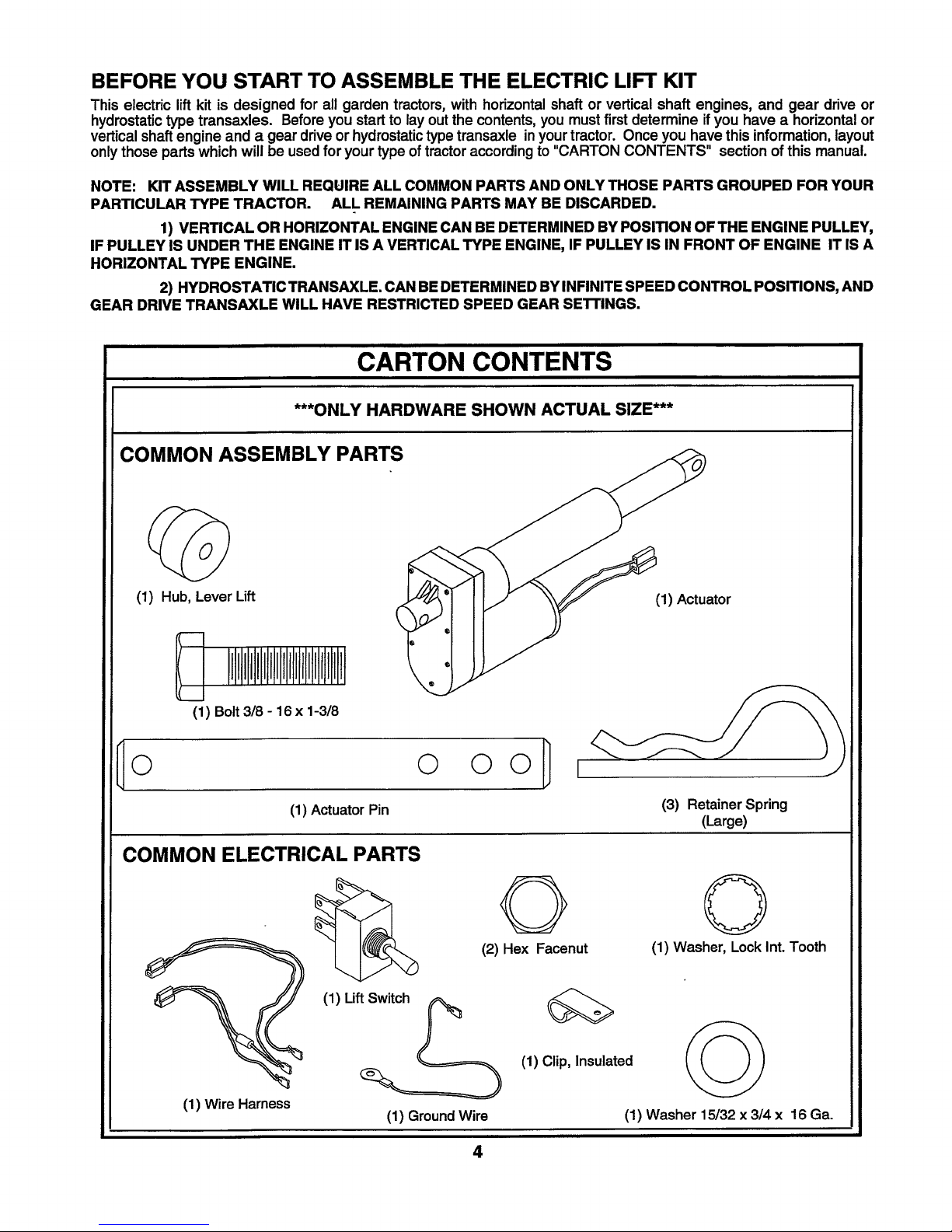
BEFORE YOU START TO ASSEMBLE THE ELECTRIC LIFT KIT
This electric lift kit is designed for all garden tractors, with horizontalshaft or vertical shaft engines, and gear drive or
hydrostatic type transaxles. Before you start to lay out the contents, you must first determine if you have a horizontal or
vertical shaft engine and a gear drive or hydrostatic type transaxle inyour tractor. Once you have this information, layout
only those parts which will be used for your type of tractor according to "CARTON CONTENTS" section of this manual.
NOTE: KIT ASSEMBLY WILL REQUIRE ALL COMMON PARTS AND ONLY THOSE PARTS GROUPED FOR YOUR
PARTICULAR TYPE TRACTOR. ALL REMAINING PARTS MAY BE DISCARDED.
1) VERTICAL OR HORIZONTAL ENGINE CAN BE DETERMINED BY POSITION OF THE ENGINE PULLEY,
IF PULLEY IS UNDER THE ENGINE IT IS A VERTICAL TYPE ENGINE, IF PULLEY IS IN FRONT OF ENGINE IT IS A
HORIZONTAL TYPE ENGINE.
2) HYDROSTATIC TRANSAXLE. CAN BE DETERMINED BY INFINITE SPEED CONTROL POSITIONS, AND
GEAR DRIVE TRANSAXLE WILL HAVE RESTRICTED SPEED GEAR SE'n'INGS.
CARTON CONTENTS
***ONLY HARDWARE SHOWN ACTUAL SIZE***
COMMON ASSEMBLY PARTS
(1) Hub, Lever Lift
(1) Bolt 3/8 - 16 x 1-3/8
0 0 O0 I
(1) Actuator Pin
COMMON ELECTRICAL PARTS
O
(2) Hex Facenut
(1) Actuator
(3) RetainerSpring
(Large)
Q
(1) Washer, LockInt.Tooth
(1) Wire Harness
(1) Lift_
(1) GroundWire
4
(1) Clip, Insulated
(1) Washer 15/32 x 3/4 x 16 Ga.
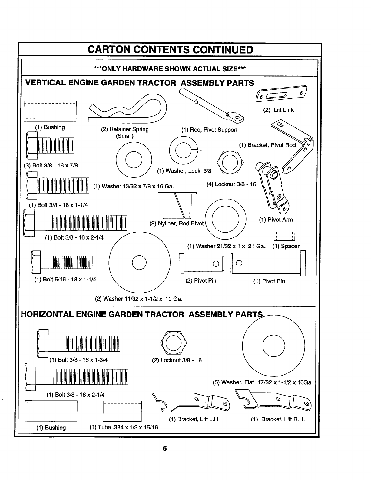
CARTON CONTENTS CONTINUED
***ONLY HARDWARE SHOWN ACTUAL SIZE***
VERTICAL ENGINE GARDEN TRACTOR ASSEMBLY PARTS
i_ j))-_ _ (2) LiftLink
(1) Bushing (2) RetainerSpring (1) Rod, Pivot Support _.._
(Small)
(1) Bracket,
(1) Washer 13/32 x 7/8 x 16 Ga. (4) Locknut 3/8 - 1
I I
(1) Bolt318- 16 x 1-1/4 1 ',
I I
I I
(2) Nyliner, Rod Pivot (1) Pivot Arm
P_vot_
(1) Bolt 3/8 - 16 x 2-1/4
(1) Washer21/32 x 1 x 21 Ga. (1) Spacer
(2) PivotPin (1) Pivot Pin
(2) Washer 11/32 x 1-1/2 x 10 Ga.
HORIZONTAL ENGINE GARDEN TRACTOR ASSEMBLY
rIIIJIllflII
_(1) Bolt 3/8 - 16 x 1-3/4
(2) Locknut 3/8- 16
(5) Washer, Flat 17/32 x 1-1/2 x 10Ga.
(1) Bolt 3/8 - 16 x 2-1/4
1
(1) Bushing
(1) Tube .384 x 1/2 x 15/16
iI (1) Bracket, LiftL.H.
(1) Bracket, Lift R.H.
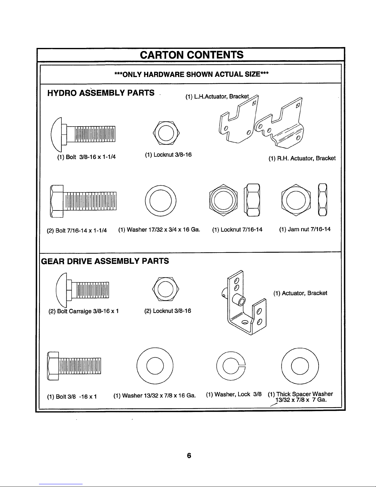
CARTON CONTENTS
***ONLY HARDWARE SHOWN ACTUAL SIZE***
HYDRO ASSEMBLY PARTS
G
(1) Bolt 3/8-16 x 1-1/4
(2) Bolt 7/16-14 x 1-1/4
GEAR DRIVE ASSEMBLY PARTS
(1) Washer 17/32 x 3/4 x 16 Ga. (1) Locknut7/16-14
(1) Locknut3/8-16
(1) LH.Actuator
(1) R.H. Actuator, Bracket
GD
(1) Jam nut7/16-14
(2) BoltCarraige 3/8-16 x I
(1) Bolt3/8 -16 x I
G
(2) Locknut3/8-16
(1) Washer 13/32 x 7/8 x 16 Ga.
6
0
,J
%
(1) Washer, Lock 3/8
(1) Actuator, Bracket
(1) Thick Spacer Washer
13/32 x 7/8 x 7 Ga.
/

COMMON SET-UP
i
THESE ARE THE TOOLS YOU
WILL NEED FOR ASSEMBLY.
(1) 3/16" Allen Wrench
(1) 1/2" Wrench
(2) 9/16" Wrenches
(1) 5/8" Wrench
(1) 11/16" Wrench
(1) Fiat Blade Screwdriver
(1) 9/16" Socket
(1) 5/8" Socket
(1) 11/16" Socket
(1) Drive Ratchet
(1) 3" or longerExtension
(1) PhillipsScrewdriver
CAUTION: BEFORE ASSEMBLING ACTUATOR KIT TO TRACTOR:
Depress clutch/brake pedal fully and set parking brake.
Place gearshift/motion control lever in "NEUTRAL" position.
Place attachment clutch in "DISENGAGED" position.
Turn ignition key "OFF" and remove key.
Make sure the blade and all moving parts have completely stopped.
Disconnect spark plug wire from spark plug and place wire where it cannot come in
contact with plug.
NOTE: Whenright hand (R.H.) andleft hand (L.H.) arementionedinthis manual, itmeans when youareseated onthe tractor,
in the operator'sposition.
NOTE: THE ILLUSTRATIONS SHOWN IN THIS MANUAL ARE TO AID INTHE ASSEMBLY AND OPERATION OF THIS
KIT. THEY MAY OR MAY NOT SHOW YOUR PARTICULAR TRACTOR MODEL.
SET-UP (See Figs. 1,2 & 3)
• Remove mower deck ifinstalled(referto your "Tractor
Owner's Manual" for instructions).
• Remove cap, E-Ring, andwasherfrom axle on left rear
wheel.
• Place a suitable size block of wood under drawbar
bracket.
• Remove rear wheel.
• ON BAND BRAKE MODELS ONLY: Remove hex bolt,
Iockwasher and flat washer indicated by arrow, from
transaxle and discard.
JAM
NUT
• Relieve any tension on attachment lift spring by
loosening jam nutand adjustment bolt.
• Remove socket/hex head screw from lift control lever.
Remove lift lever and washers (if equipped).
NOTE: Use block of wood to assist in lift handle
removal. Save washers for later use.
• Install washers, if removed earlier, on lift lever ]]ub.Fit
lift lever hub on splined lift shaft and secure with
3/8-16 x 1-3/8 hex bolt, provided with kit.
LIFT
LEVER
O
DRAWBARo(
QBRACKET
Q
Q
BOLT
ATrACHMENT
LIFT SPRING
"FOR BAND
BRAKE MODELS
ONLY"
WASHERS
(IFEQUIPPED)
Fig. 2
SOCKET HEAD/
HEX HEAD
SCREW
WASHERS
(IF EQUIPPED)
LIFT
LEVER
HUB
HEX BOLT
LOCKWASHER
AND FLATWASHER
Fig. 1 7
SPLINED
LIFT SHAFT
Fig. 3
HEX BOLT
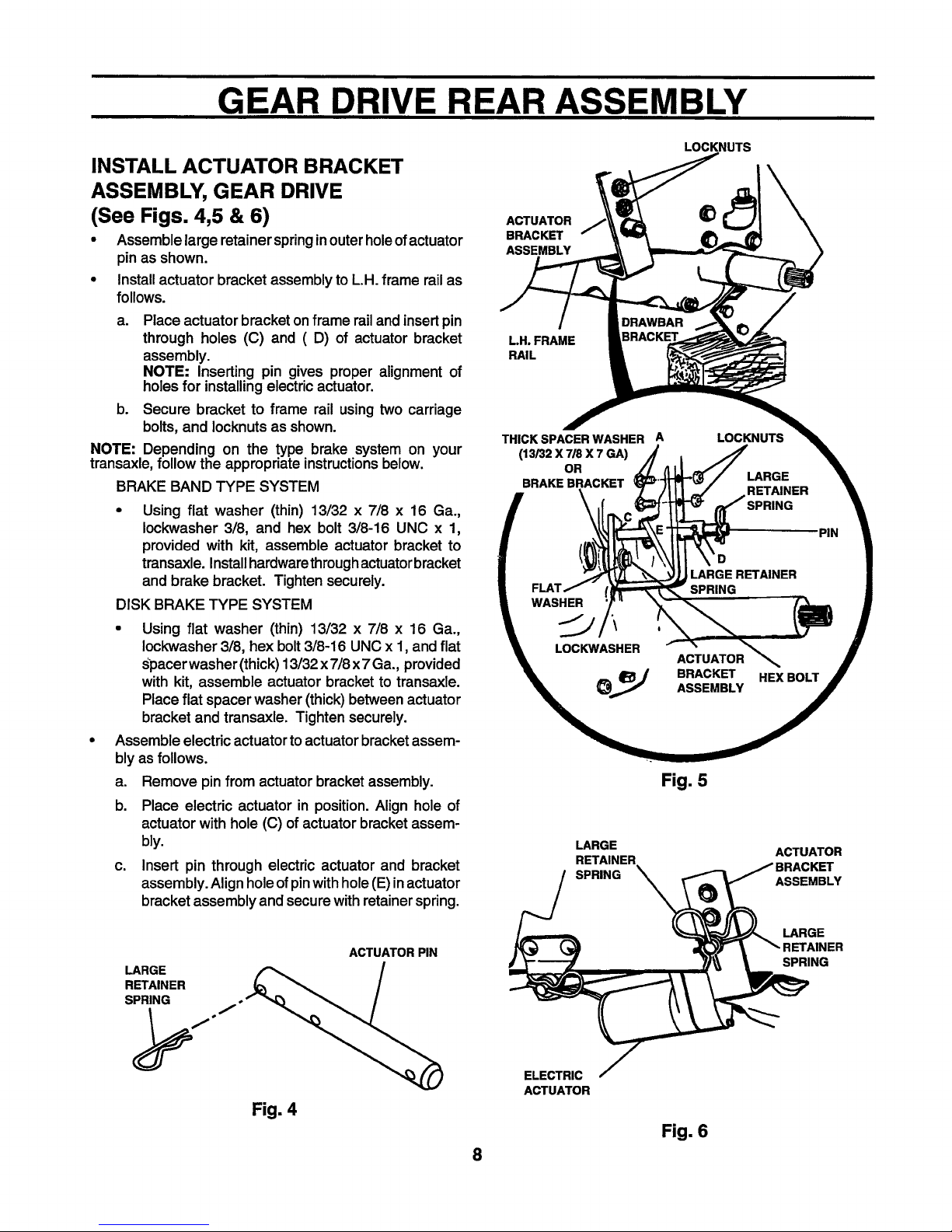
GEAR DRIVE REAR ASSEMBLY
INSTALL ACTUATOR BRACKET
ASSEMBLY, GEAR DRIVE
(See Figs. 4,5 & 6)
• Assemblelarge retainerspringinouterholeofactuator
pin as shown.
• Installactuator bracket assemblytoLH. frame rail as
follows.
a. Place actuator bracket on frame rail and insert pin
through holes (C) and (D) of actuator bracket
assembly.
NOTE: Inserting pin gives proper alignment of
holesfor installingelectricactuator.
b. Secure bracket to frame rail using two carriage
bolts,and Iocknutsas shown.
NOTE: Depending on the type brake system on your
transaxle, followthe appropriate instructionsbelow.
BRAKE BAND TYPE SYSTEM
• Using flat washer (thin) 13/32 x 7/8 x 16 Ga.,
Iockwasher 3/8, and hex bolt 3/8-16 UNC x 1,
provided with kit, assemble actuator bracket to
transaxle. Installhardwarethroughactuatorbracket
and brake bracket. Tighten securely.
DISK BRAKE TYPE SYSTEM
• Using flat washer (thin) 13/32 x 7/8 x 16 Ga.,
Iockwasher 3/8, hex bolt 3/8-16 UNC x 1, and flat
Spacerwasher (thick) 13/32x 7/8x 7 Ga., provided
with kit, assemble actuator bracket to transaxle.
Place flat spacer washer (thick) between actuator
bracket and transaxle. Tighten securely.
Assemble electric actuator to actuator bracket assem-
bly as follows.
a. Remove pin from actuator bracket assembly.
b. Place electric actuator in position. Align hole of
actuator with hole (C) of actuator bracket assem-
bly.
c. Insert pin through electric actuator and bracket
assembly. Align hole of pinwith hole (E)in actuator
bracket assembly and secure with retainer spring.
LOCKNUTS
ACTUATOR
BRACKET
ASSEMBLY
L.H. FRAME
RAIL
THICK SPACER WASHER A LOCKNUTS
(13/32 X 7/8 X 7 GA)
OR
BRAKE BRACKET
_D PIN
m ;LARGE RETAINER II
I SPRING |
\w,s I
_,, _J BRACKET HEX BOLT _ r
Fig. 5
LARGE ACTUATOR
RETAINER
SPRING ASSEMBLY
tKET
LARGE
RETAINER
SPRING
J
Fig. 4
ACTUATOR PIN
LARGE
SPRING
ELECTRIC
ACTUATOR
Fig. 6
8
 Loading...