

Craftsman 917.20403 Operator's Manual

Operator's Manual
FIN°
GAR
24.0 HP,* 54"
Electric Start
Automatic
Model No.
917.20403
• EspaSol, p. 41
Transmission
TRACTO
Mower
This product has a low emission engine which operates
differently from previously built engines. Before you start the
engine, read and understand this manual.
IMPORTANT:
Read and follow all Safety
Rules and Instructions before
operating this equipment.
Sears Brands Management Corporation, Hoffman Estates, IL 60179 U.S.A.
Visit our Craftsman website: www.craftsman.com
* The power rating as declared by the engine manufacturer is the
average gross power output at the specified RPM of a typical
production engine for the engine model measured using SAE
Standards for engine gross power. Please refer to the engine
manufacturer for details.
586138696 Rev. 3
For answers to your questions
about this product, call:
1-888-331-4569
Craftsman Customer Help Line
* La potencia nominal declarada por el fabricante del motor es la
salida media de potencia bruta alas RPM especificadas de un
motor de serie tipico para el modelo de motor, medida segQn
las normas SAE sobre potencia bruta de motor. Para mas
informaci6n, consulte al fabricante del motor.

Warranty .................................................. 2
Safety Rules ............................................ 3
Product Specifications ............................. 6
Assembly/Pre-Operation ......................... 7
Operation ............................................... 13
Maintenance .......................................... 23
Service and Adjustments ....................... 38
Storage .................................................. 35
Troubleshooting ..................................... 36
Sears Service ......................... Back Cover
Maintenance Schedule .......................... 23
CRAFTSMAN FULL WARRANTY
FOR TWO YEARS from the date of purchase, all non-expendable parts of this riding equipment are
warranted against any defects in material or workmanship. A defective non-expendable part will receive
free in-home repair or replacement if repair is unavailable.
BATTERY LiMiTED WARRANTY
FOR 90 DAYS from the date of purchase, the battery (an expendable part) of this riding equipment is
warranted against any defects in material or workmanship. A new battery will be supplied free of charge.
You are responsible for the labor cost of battery installation.
ADDiTiONAL LIMITED WARRANTIES
In the following additional warranties, you are responsible for the labor cost of part installation after
the second year from the date of purchase.
FOR FIVE YEARS from the date of purchase, the frame of this riding equipment is warranted against any
defects in material or workmanship. A new frame will be supplied free of charge.
FOR TEN YEARS from the date of purchase, the front axle of this riding equipment is warranted against any
defects in material or workmanship. A new front axle will be supplied free of charge.
FOR AS LONG AS IT IS USED by the original owner after the tenth year from the date of purchase, the
cast iron front axle (if equipped) of this riding equipment is warranted against any defects in material or
workmanship. With proof of purchase, a new cast iron front axle will be supplied free of charge.
WARRANTY SERVICE
For warranty coverage details to obtain free repair or replacement, call 1-888-331-4569 or visit the web
page: www.craftsman, com/warranty
In all cases above, if part repair or replacement is impossible, the riding equipment will be replaced free of
charge with the same or an equivalent model.
All of the above warranty coverage is void if this riding equipment is ever used while providing commercial
services or if rented to another person.
This warranty covers ONLY defects in material and workmanship. Warranty coverage does NOT
include:
• Expendable parts (except battery) that can wear out from normal use within the warranty period, including
but not limited to blades, spark plugs, air cleaners, belts, and oil filters.
• Standard maintenance servicing, oil changes, or tune-ups.
• Tire replacement or repair caused by punctures from outside objects, such as nails, thorns, stumps, or
glass.
• Tire or wheel replacement or repair resulting from normal wear, accident, or improper operation or
maintenance.
• Repairs necessary because of operator abuse, including but not limited to damage caused by towing
objects beyond the capability of the riding equipment, impacting objects that bend the frame, axle
assembly or crankshaft, or over-speeding the engine.
• Repairs necessary because of operator negligence, including but not limited to, electrical and mechanical
damage caused by improper storage, failure to use the proper grade and amount of engine oil, failure
to keep the deck clear of flammable debris, or failure to maintain the riding equipment according to the
instructions contained in the operator's manual.
• Engine (fuel system) cleaning or repairs caused by fuel determined to be contaminated or oxidized
(stale). In general, fuel should be used within 30 days of its purchase date.
• Normal deterioration and wear of the exterior finishes, or product label replacement.
This warranty gives you specific legal rights, and you may also have other rights which vary from state to
state.
Sears Brands Management Corporation, Hoffman Estates, IL 60179
2

,_DANGER: This cutting machine is capable of amputating hands and feet and
throwing objects. Failure to observe the following safety instructions could result
in serious injury or death.
_,WARNING: In order to prevent acciden-
tal starting when setting up, transporting,
adjusting or making repairs, always discon-
nect spark plug wire and place wire where
it cannot contact spark plug.
_,WARNING: Do not coast down a hill in
neutral, you may lose control of the tractor.
_,WARNING: Tow only the attachments
that are recommended by and comply with
specifications of the manufacturer of your
tractor. Use common sense when towing.
Operate only at the lowest possible speed
when on a slope. Too heavy of a load, while
on a slope, is dangerous. Tires can lose
traction with the ground and cause you to
lose control of your tractor.
_,WARNING: Engine exhaust, some of
its constituents, and certain vehicle compo-
nents contain or emit chemicals known to
the State of California to cause cancer and
birth defects or other reproductive harm.
_,WARNING: Battery posts, terminals and
related accessories contain lead and lead
compounds, chemicals known to the State of
California to cause cancer and birth defects
or other reproductive harm. Wash hands
after handling.
I. CHILDREN
_,WARNING! CHILDREN CAN BE IN-
JURED BYTHIS EQUIPMENT. TheAmeri-
can Academy of Pediatrics recommends
that children be a minimum of 12 year of
age before operating a pedestrian controlled
lawn mower and a minimum of 16 years of
age before operating a riding lawn mower.
_IbWARNING! CHILDREN CAN BE
SERIOUSLY INJURED OR KILLED BY
THIS EQUIPMENT. Carefully read and
follow all of the safety instructions below.
Tragic accidents can occur if the operator
is not alert to the presence of children.
Children are often attracted to the machine
and the mowing activity. Never assume
that children will remain where you last
saw them.
• Keep children out of the mowing area
and in the watchful care of a responsible
adult other than the operator.
• Be alert and turn machine off if a child
enters the area.
• Before and while backing, look behind
and down for small children.
• Never carry children, even with the
blades shut off. They may fall off and
be seriously injured or interfere with safe
machine operation. Children who have
been given rides in the past may suddenly
appear in the mowing area for another
ride and be run over or backed over by
the machine.
• Never allow children to operate the ma-
chine.
• Use extreme caution when approaching
blind corners, shrubs, trees, or other
objects that may block your view of a
child.
li.
GENERAL OPERATION
o
Read, understand, and follow all instruc-
tions on the machine and in the manual
before starting.
• Do not put hands or feet near rotating
parts or under the machine. Keep clear
of the discharge opening at all times.
• Only allow responsible adults, who are
familiar with the instructions, to operate
the machine.
• Clear the area of objects such as rocks,
toys, wire, etc., which could be picked
up and thrown by the blades.
• Ensure the area is clear of bystanders
before operating. Stop machine if anyone
enters the area.
• Never carry passengers.
• Do not mow in reverse unless absolutely
necessary. Always look down and behind
before and while backing.
• Never direct discharged materialtoward
anyone. Avoid discharging material
against a wall or obstruction. Material
may ricochet back toward the operator.
Stop the blades when crossing gravel
surfaces.
• Do notoperate machinewithouttheentire
grass catcher, discharge chute, or other
safety devices in place and working.
3
• Slow down before turning.
• Never leave a running machine unat-
tended. Always turn off blades, set
parking brake, and stop engine before
dismounting. Manually lock ignition
swkch.(See "MANUALLY LOCKING
THE SmartSwitch TM IGNMON" in the
Operation section of this manual).
• Disengage blades when not mowing.
Shut off engine and wait for all parts to
come to a complete stop before cleaning
the machine, removing the grass catcher,
or unclogging the discharge chute.
• Operate machine onlyin daylight or good
artificial light.
• Do not operate the machine while under
the influence of alcohol or drugs.
• Watch for traffic when operating near or
crossing roadways.
• Use extreme caution when loading or
unloading the machine into a trailer or
truck.
• AIways wear eye protection when operat-
ing machine.
• Use ear protectors to avoid damage to
hearing.
• Data indicates that operators, age 60
years and above, are involved in a large
percentage of riding mower-related inju-
ries. These operators should evaluate
their ability to operate the riding mower
safely enough to protect themselves and
others from serious injury.
• Followthemanufacturer'srecommenda-
tion for wheel weights or counterweights.
• Keep machine free of grass, leaves or
other debris build-up which can touch hot
exhaust / engine parts and burn. Do not
allow the mower deck to plow leaves or
other debris which can cause build-up
to occur. Clean any oil or fuel spillage
before operating or storing the machine.
Allow machine to coo! before storage.
Iii. SLOPE OPERATION
,_WARNING! When loading or unloading
this machine, do not exceed the maximum
recommended operation angle of 15 °.
Slopes are a major factor related to loss of
control and tip-over accidents, which can
result in severe injury or death. Operation
on all slopes requires extreme caution. If
you cannot back up the slope or if you feel
uneasy on it, do not mow it.
• Mow up and down slopes, not across.
• Watch for holes, ruts, bumps, rocks, or
other hidden objects. Uneven terrain
could overturn the machine. Tall grass
can hide obstacles.
• Choose a low ground speed so that you
will not have to stop or shift while on the
slope.
• Do not mow on wet grass. Tires may
lose traction. Always keep the machine
in gear when going down slopes.
• Do not shift to neutral and coast downhill.
• Avoid starting, stopping, or turning on a
slope. Ifthetires Iosetraction, disengage
the blades and proceed slowly straight
down the slope.
• Keep all movement on the slopes slow
and gradual. Do not make sudden
changes in speed or direction, which
could cause the machine to roll over.
• Use extreme caution while operating
machine with grass catchers or other
attachments; they can affect the stabil-
ity of the machine. Do no use on steep
slopes.
• Do not try to stabilize the machine by
putting your foot on the ground.
• Do not mow near drop-offs, ditches,
or embankments. The machine could
suddenly roll over if a wheel is over the
edge or if the edge caves in.
• If machine stops while going uphill,
disengage blades, shift into reverse and
back down slowly.
• Do not turn on slopes unless necessary,
and then, turn slowly and gradually
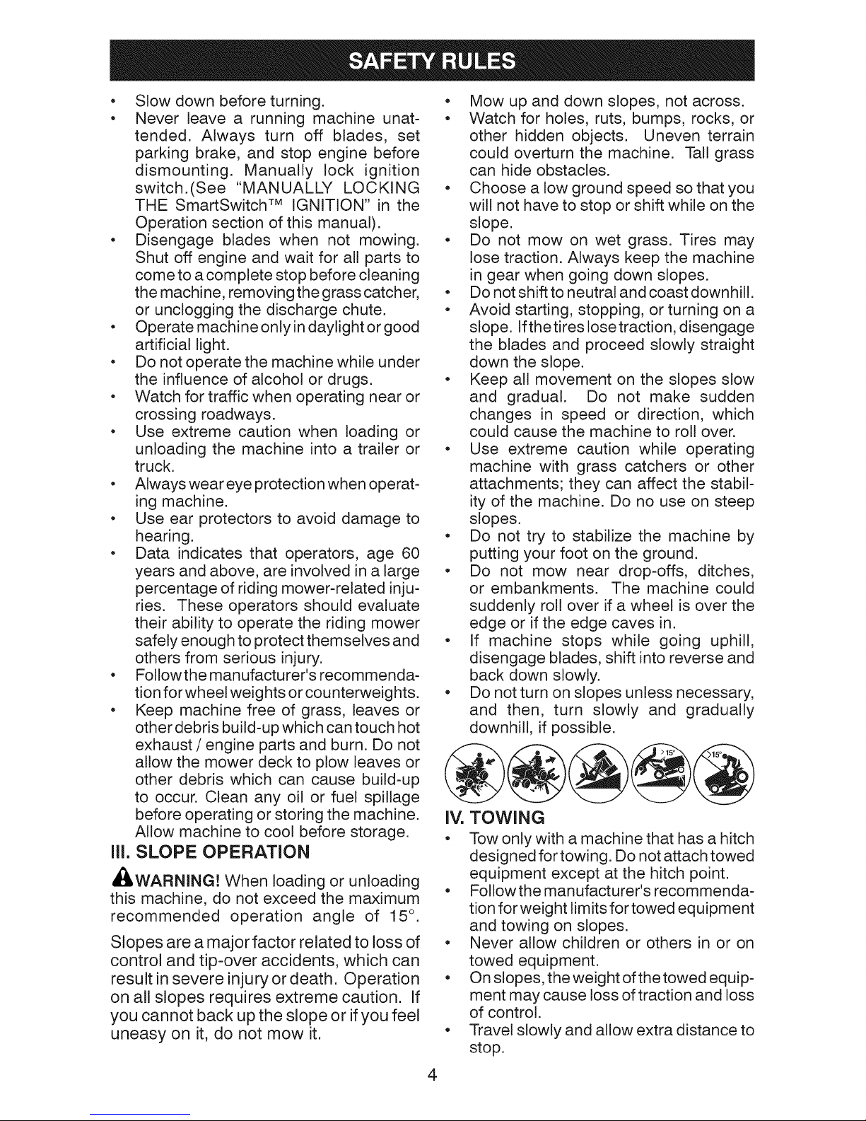
downhill, if possible.
IV. TOWING
o
Tow only with a machine that has a hitch
designed for towing. Do not attach towed
equipment except at the hitch point.
o Followthemanufacturer'srecommenda-
tion for weight limits for towed equipment
and towing on slopes.
• Never allow children or others in or on
towed equipment.
• On slopes, the weight ofthetowed equip-
ment may cause loss of traction and loss
of control.
• Travel slowly and allow extra distance to
stop.
4
V. SERVICE
SAFE HANDLING OF GASOLINE
To avoid personal injury or property dam-
age, use extreme care in handling gasoline.
Gasoline is extremely flammable and the
vapors are explosive.
• Extinguish all cigarettes, cigars, pipes,
and other sources of ignition.
• Use only approved gasoline container.
• Never remove gas cap or add fuel with
the engine running.
• Allow engine to cool before refueling.
• Never fuel the machine indoors.
• Neverstorethe machine orfuel container
where there is an open flame, spark, or
pilot light such as on a water heater or
other appliances.
• Never fill containers inside a vehicle or
on a truck or trailer bed with plastic liner.
Always place containers on the ground
away from your vehicle when filling.
• Remove gas-powered equipment from
the truck or trailer and refuel it on the
ground. If this is not possible, then refuel
such equipment with a portable container,
rather than from a gasoline dispenser
nozzle.
• Keep the nozzle in contact with the rim
of the fuel tank or container opening at
all times until fueling is complete. Do not
use a nozzle lock-open device.
• Iffuelis spilled on clothing, change cloth-
ing immediately.
• Never overfill fuel tank. Replace gas cap
and tighten securely.
GENERALSERVICE
• Never operate machine in a closed area.
• Keepall nutsand boltstighttoensurethe
equipment is in safe working condition.
• Nevertamperwithsafetydevices. Never
interfere with the intended function of a
safety device or reduce the protection
provided by a safety device. Checkthere
proper operation regularly. NEVER oper-
ate a machine with a safety device that
does not function properly.
• Keep machine free of grass, leaves, or
other debris build-up. Clean oil or fuel
spillage and remove any fue!-soaked
debris. Allow machine to cool before
storing.
• If you strike a foreign object, stop and
inspectthe machine. Repair, if necessary,
before restarting.
• Never make any adjustments or repairs
with the engine running.
• Checkgrasscatchercomponentsandthe
discharge chute frequently and replace
with manufacturer's recommended parts,
when necessary.
• Mower blades are sharp. Wrapthe blade
or wear gloves, and use extreme caution
when servicing them.
• Check brake operation frequently. Adjust
and service as required.
• Maintain orreplace safetyand instruction
labels, as necessary.
Use ear protectors to avoid damage to hearing.
Always wear eye protection when operating machine.
5

PRODUCT SPECIFICATIONS
Gasoline Capacity 4.0 Gallons/15,14 L
and type: Regular Unleaded *
Oil Type: SAE30 (above 32°F/0°0)
API: SG-SL) SAE 5W30 (below 32°F/0°0)
Oil Capacity: W/Filter: 64 Oz./1,89 L
W/out Filter: 60 Oz./1,77 L
Spark Plug: Champion RC12YC
(Gap: .030"/0,76 mm)
Charging System: 16Amps @ 3600 RPM
Battery: Amp/Hr: 28
Blade Bolt Torque: 45-55 Ft. Lbs./62-75 Nm
&Gasoline containing up to 10% ethanol (El0) is
acceptable for use in this machine. The use of
any gasoline exceeding 10% ethanol (El0) will
void the product warranty.
Min. CCA: 230
Case size: U1R
CONGRATULATIONS on your purchase of
a new tractor. It has been designed, engi-
neered and manufactured to give you the best
possible dependability and performance.
Should you experience any problem you can-
not easily remedy, please contact a Sears or
other qualified service center. We have com-
petent, well-trained representatives and the
proper tools to service or repair this tractor.
Please read and retain this manual. The
instructions will enable you to assemble
and maintain your tractor properly. Always
observe the "SAFETY RULES".
CUSTOMER RESPONSIBILITIES
• Read and observe the safety rules.
• Follow a regular schedule in maintaining,
caring for and using your tractor.
• Follow instructions under "Maintenance"
and "Storage" sections of this manual.
• Wear proper Personal Protective Equip-
ment (PPE) while operating this machine,
including (at a minimum) sturdy footwear,
eye protection, and hearing protection.
Do not mow in shorts and/or open toed
footwear.
• Always let someone know you are outside
mowing.
_IbWARNING: This tractor is equipped with
an internal combustion engine and should
not be used on or near any unimproved
forest-covered, brush-covered or grass-
covered land unless the engine's exhaust
system is equipped with a spark arrester
meeting applicable local or state laws (if
any). If a spark arrester is used, it should
be maintained in effective working order by
the operator.
In the state of Californiathe above is required
by law (Section 4442 of the California Public
Resources Code). Other states may have
similar laws. Federal laws apply on federal
lands. A spark arrester for the muffler is
available through your nearest Sears service
center (See REPAIR PARTS manual).
REPAIR PROTECTION AGREEMENTS
Congratulations on making a smart pur-
chase. Your new Craftsman® product is
designed and manufactured for years of
dependable operation. But like all products,
it may require repair from time to time. That's
when having a Repair Protection Agreement
can save you money and aggravation.
Purchase a Repair Protection Agreement
now and protect yourself from unexpected
hassle and expense.
Here's what's included in the Agreement:
• Expert service by our 12,000 professional
repair specialists.
Unlimited service and no charge for parts
and labor on all covered repairs.
Product replacement if your covered
product can't be fixed.
Discount of 25% from regular price of
service and service-related parts not
covered bythe agreement; also, 25% off
regular price of preventive maintenance
check.
Fast help by phone - phone support
from a Sears representative on products
requiring in-home repair, plus convenient
repair scheduling.
Once you purchase the Agreement, a simple
phone call is all that it takes for you to sched-
ule service. You can call anytime day or night,
or schedule a service appointment online.
Sears has over 12,000 professional repair
specialists, who have access to over 4.5
million quality parts and accessories. That's
the kind of professionalism you can count on
to help prolong the life of your new purchase
for years to come. Purchase your Repair
Protection Agreement today!
Some limitations and exclusions apply.
For prices and additional information call
1-800-827=6655.
SEARS INSTALLATION SERVICE
For Sears professional installation of home
appliances, garage door openers, water
heaters, and other major home items, in the
U.S.A. call 1-800=4-MY=HOME®.
6
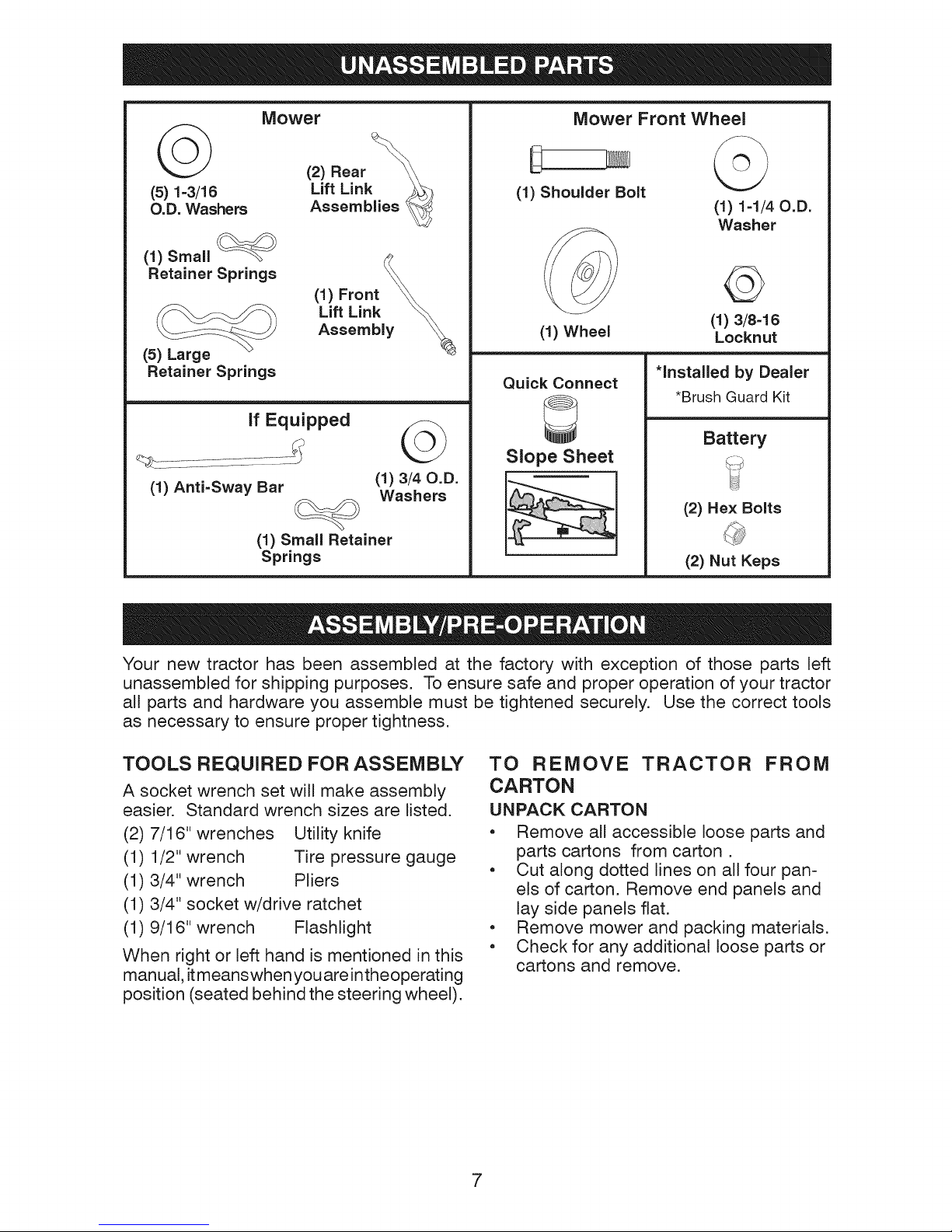
Mower
(5) 1-3/16 Assemblies
O.D. Washers
(1) Small
Retainer Springs
(5) Large
Retainer Springs
if Equipped
(1) Anti=Sway Bar
(1) Small Retainer
Springs
Lift Link ___
(1) Front \_
Lift Link _
Assembly
©
(1)3/4 o.o.
Washers
Mower Front Wheel
(1) Shoulder Bolt
(1) Wheel
Quick Connect
3
Slope Sheet
©
(1)1-1/4o.o.
Washer
(1) 3/8=16
Locknut
*installed by Dealer
*Brush Guard Kit
Battery
(2) Hex Bolts
(2) Nut Keps
Your new tractor has been assembled at the factory with exception of those parts left
unassembled for shipping purposes. To ensure safe and proper operation of your tractor
all parts and hardware you assemble must be tightened securely. Use the correct tools
as necessary to ensure proper tightness.
TOOLS REQUIRED FOR ASSEMBLY
A socket wrench set will make assembly
easier. Standard wrench sizes are listed.
(2) 7/16" wrenches Utility knife
(1) 1/2" wrench Tire pressure gauge
(1) 3/4" wrench Pliers
(1) 3/4" socket w/drive ratchet
(1) 9/16" wrench Flashlight
When right or left hand is mentioned in this
manual, it meanswhenyou areintheoperating
position (seated behind the steering wheel).
TO REMOVE TRACTOR FROM
CARTON
UNPACK CARTON
• Remove all accessible loose parts and
parts cartons from carton.
• Cut along dotted lines on all four pan-
els of carton. Remove end panels and
lay side panels flat.
• Remove mower and packing materials.
• Check for any additional loose parts or
cartons and remove.
7
BEFORE REMOVING TRACTOR
FROM SKID
CONNECT BATTERY
_WARNING: Do not short battery ter-
minals by allowing a wrench or any other
object to contact both terminals at the same
time. Before connecting battery, remove
metal bracelets, wristwatch bands, rings, etc.
Positive terminal must be connected first to
prevent sparking from accidental grounding.
NOTE: If this battery is put into service after
month and year indicated on label (label is
located between terminals) charge battery
for minimum ofone hour at 6-10 amps. (See
"BATTERY" in the Maintenance section of
this manual for charging instructions.)
• Determinebatterylocation. Batteryloca-
tion will be under the seat or the hood.
o
Lift seat pan or hood to raised position.
o
Remove two terminal caps and discard.
o
First connect RED battery cable to
positive (+) terminal with bolt and nut as
shown. Tighten securely. Slide terminal
cover over terminal.
• Connect BLACK grounding cable to
negative (-) terminal with remaining bolt
and nut. Tighten securely.
• Lower seat pan or hood.
NOTE: For battery installation see
"REPLACING BATTERY" in the Service and
Adjustments section in this manual.
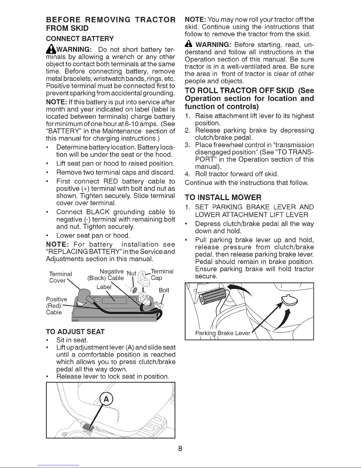
Terminal Negative Nut
Cover (Black) Cable Cap
Label_
Positive
(Red)
Cable
Bolt
NOTE: You may now roll your tractor offthe
skid. Continue using the instructions that
follow to remove the tractor from the skid.
AI_ WARNING: Before starting, read, un-
derstand and follow all instructions in the
Operation section of this manual. Be sure
tractor is in a well-ventilated area. Be sure
the area in front of tractor is clear of other
people and objects.
TO ROLL TRACTOR OFF SKID (See
Operation section for location and
function of controls)
1. Raise attachment lift lever to its highest
position,
2. Release parking brake by depressing
clutch/brake pedal,
3. Place freewheel control in "transmission
disengaged position" (See "TO TRANS-
PORT" in the Operation section of this
manual).
4, Roll tractor forward off skid.
Continue with the instructions that follow.
TO iNSTALL MOWER
1. SET PARKING BRAKE LEVER AND
LOWER ATTACHMENT LIFT LEVER
• Depress clutch/brake pedal all the way
down and hold.
Pull parking brake lever up and hold,
release pressure from clutch/brake
pedal, then release parking brake lever.
Pedal should remain in brake position.
Ensure parking brake will hold tractor
secure.
TO ADJUST SEAT
• Sit in seat.
• Lift up adjustment lever (A) and slide seat
until a comfortable position is reached
which allows you to press clutch/brake
pedal all the way down.
• Release lever to lock seat in position.
Parkin( Brake Lever
8
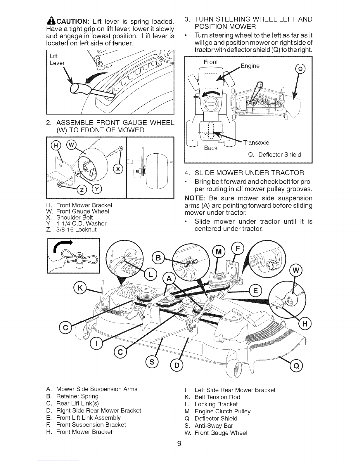
,_CAUTION: Lift lever is spring loaded.
Have a tight grip on lift lever, lower it slowly
and engage in lowest position. Lift lever is
located on left side of fender.
2. ASSEMBLE FRONT GAUGE WHEEL
(W) TO FRONT OF MOWER
Jli
H, Front Mower Bracket
W, Front Gauge Wheel
X. Shoulder Bolt
Y. 1-1/40.D. Washer
Z, 3/8-16 Locknut
3. TURN STEERING WHEEL LEFT AND
POSITION MOWER
• Turn steering wheel to the left as far as it
will go and position mower on right side of
tractor with deflector shield (Q) to the right.
Front
iEngine
Back
Deflector Shield
Q.
4. SLIDE MOWER UNDER TRACTOR
• Bring belt forward and check belt for pro-
per routing in all mower pulley grooves.
NOTE: Be sure mower side suspension
arms (A) are pointing forward before sliding
mower under tractor.
• Slide mower under tractor until it is
centered under tractor.
(
,)
A. Mower Side Suspension Arms
B. Retainer Spring
C. Rear Lift Link(s)
D. Right Side Rear Mower Bracket
E. Front Lift Link Assembly
R Front Suspension Bracket
H, Front Mower Bracket
I. Left Side Rear Mower Bracket
K. Belt Tension Rod
L, Locking Bracket
M, Engine Clutch Pulley
Q, Deflector Shield
S, Anti-Sway Bar
W, Front Gauge Wheel
9
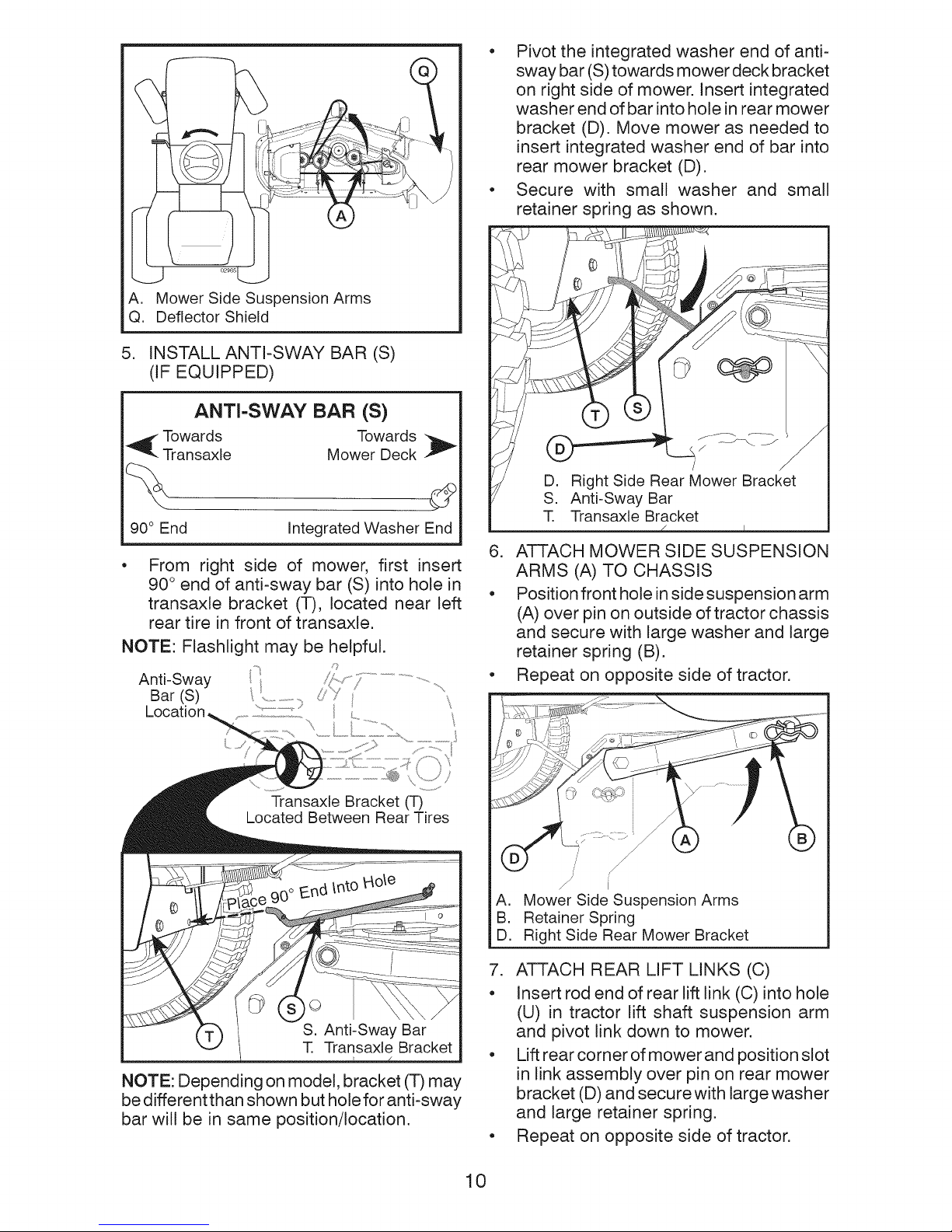
A. MowerSideSuspensionArms
Q. DeflectorShield
5. INSTALL ANTI-SWAY BAR (S)
(IF EQUIPPED)
ANTI-SWAY BAR (S)
_ Towards Towards
Transaxle Mower Deck _"
• Pivot the integrated washer end of anti-
sway bar (S) towards mower deck bracket
on right side of mower. Insert integrated
washer end of bar into hole in rear mower
bracket (D). Move mower as needed to
insert integrated washer end of bar into
rear mower bracket (D).
• Secure with small washer and small
retainer spring as shown.
90° End Integrated Washer End
From right side of mower, first insert
90 ° end of anti-sway bar (S) into hole in
transaxle bracket (T), located near left
rear tire in front of transaxle.
NOTE: Depending on model, bracket (T) may
be different than shown but hole for anti-sway
bar will be in same position/location.
6. ATTACH MOWER SIDE SUSPENSION
ARMS (A) TO CHASSIS
• Position front hole in side suspension arm
(A) over pin on outside of tractor chassis
and secure with large washer and large
retainer spring (B).
• Repeat on opposite side of tractor.
S
I
A,
Mower Side Suspension Arms
B.
Retainer Spring
D.
Right Side Rear Mower Bracket
7. ATTACH REAR LIFT LINKS (C)
• Insert rod end of rear lift link (C) into hole
(U) in tractor lift shaft suspension arm
and pivot link down to mower.
• Lift rear corner of mower and position slot
in link assembly over pin on rear mower
bracket (D) and secure with large washer
and large retainer spring.
• Repeat on opposite side of tractor.
10
m
\
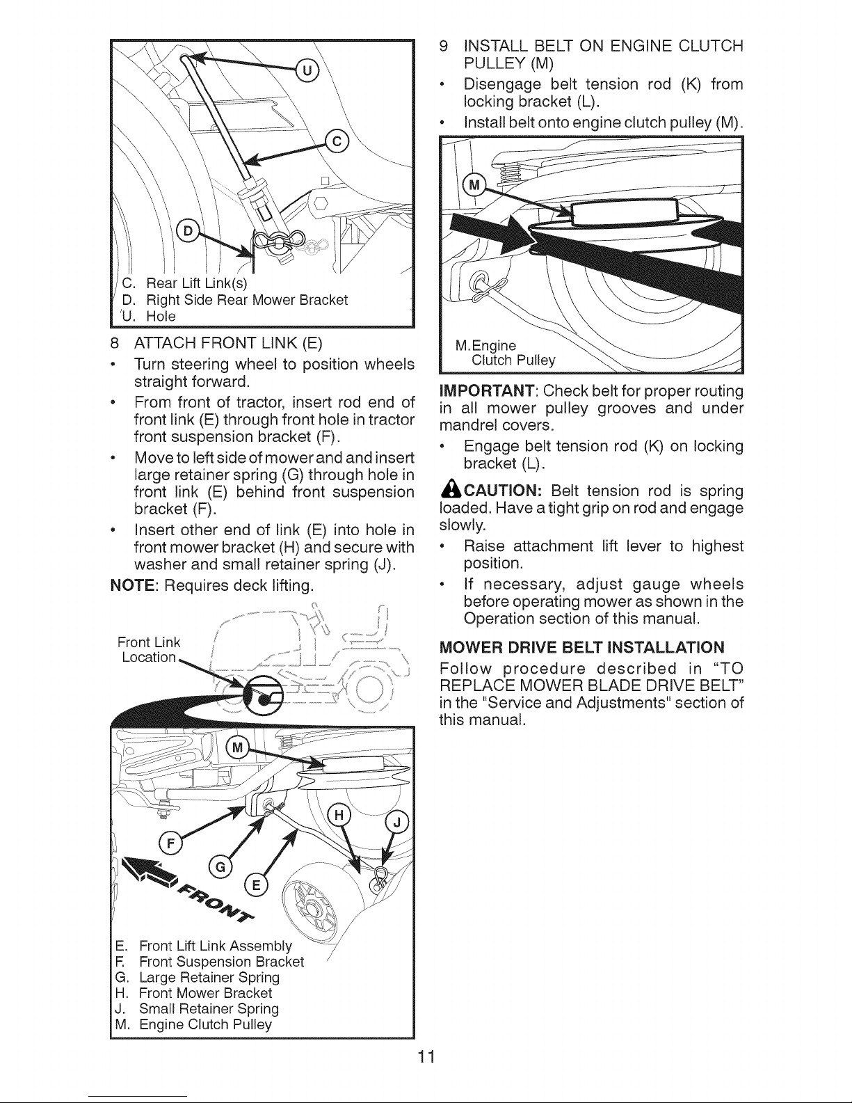
C. Rear Lift Link(s)
D. Right Side Rear Mower Bracket
'U. Hole
8
ATTACH FRONT LINK (E)
• Turn steering wheel to position wheels
straight forward.
• From front of tractor, insert rod end of
front link (E) through front hole in tractor
front suspension bracket (F).
• Move to left side of mower and and insert
large retainer spring (G) through hole in
front link (E) behind front suspension
bracket (F).
• Insert other end of link (E) into hole in
front mower bracket (H) and secure with
washer and small retainer spring (J).
NOTE: Requires deck lifting.
9 INSTALL BELT ON ENGINE CLUTCH
PULLEY (M)
• Disengage belt tension rod (K) from
locking bracket (L).
• Install belt onto engine clutch pulley (M).
M,Engine
Clutch Pulley
IMPORTANT: Check belt for proper routing
in all mower pulley grooves and under
mandrel covers.
• Engage belt tension rod (K) on locking
bracket (L).
_CAUTION: Belt tension rod is spring
loaded. Have a tight grip on rod and engage
slowly.
• Raise attachment lift lever to highest
position.
• If necessary, adjust gauge wheels
before operating mower as shown in the
Operation section of this manual.
E. Front Lift Link Assembly
R Front Suspension Bracket
G, Large Retainer Spring
H, Front Mower Bracket
J. Small Retainer Spring
M, Engine Clutch Pulley
MOWER DRIVE BELT INSTALLATION
Follow procedure described in "TO
REPLACE MOWER BLADE DRIVE BELT"
in the "Service and Adjustments" section of
this manual.
11

CHECK TIRE PRESSURE
The tires on your tractor were overinflated at
the factory for shipping purposes. Correct
tire pressure is important for best cutting
performance.
* Reduce tire pressure to PSi shown on
tires.
CHECK DECK LEVELNESS
For best cutting results, mower housing
should be properly leveled. See "TO LEVEL
MOWER" in the Service and Adjustments
section of this manual.
CHECK FOR PROPER POSITION OF
ALL BELTS
See the figures that are shown for replacing
motion and mower blade drive belts in the
Service and Adjustments section of this man-
ual. Verify that the belts are routed correctly.
CHECK BRAKE SYSTEM
After you learn how to operate your tractor,
check to see that the brake is operating
properly. See "TO CHECK BRAKE" in the
Service and Adjustments section of this
manual.
CHECKLIST
Before you operate your new tractor, we
wish to assure that you receive the best
performance and satisfaction from this
Quality Product.
Please review the following checklist:
_" All assembly instructions have been
completed.
_" No remaining loose parts in carton.
_" Battery is properly prepared and charged.
_" Seat is adjusted comfortably and tight-
ened securely.
_" All tires are properly inflated. (For ship-
ping purposes, the tires were overinflated
at the factory).
_" Be sure mower deck is properly leveled
side-to-side/front-to-rear for best cutting
results. (Tires must be properly inflated
for leveling).
_" Check mower and drive belts. Be sure
they are routed properly around pulleys
and inside all belt keepers.
_/Check wiring. See that all connections are
still secure and wires are properly clamped.
_/ Before driving tractor, be sure freewheel
control is in "transmission engaged" posi-
tion (see "To Transport" in the Operation
section of this manual).
While learning how to use your tractor, pay ex-
tra attention tothe following important items:
_/ Engine oil is at proper level.
_/ Fuel tank is filled with fresh, clean, regular
unleaded gasoline.
_/ Become familiar with all controls, their
location and function. Operate them
before you start the engine.
v"
Be sure brake system is in safe operating
condition.
v"
Be sure Operator Presence System and
Reverse Operation System (ROS) are
working properly (See the Operation and
Maintenance sections in this manual).
v"
It is important to purge the transmission
before operating your tractor for the first
time. Follow proper starting and transmis-
sion purging instructions (See "TO START
ENGINE"and"PU RGETRANSMISSION"
in the Operation section of this manual).
12
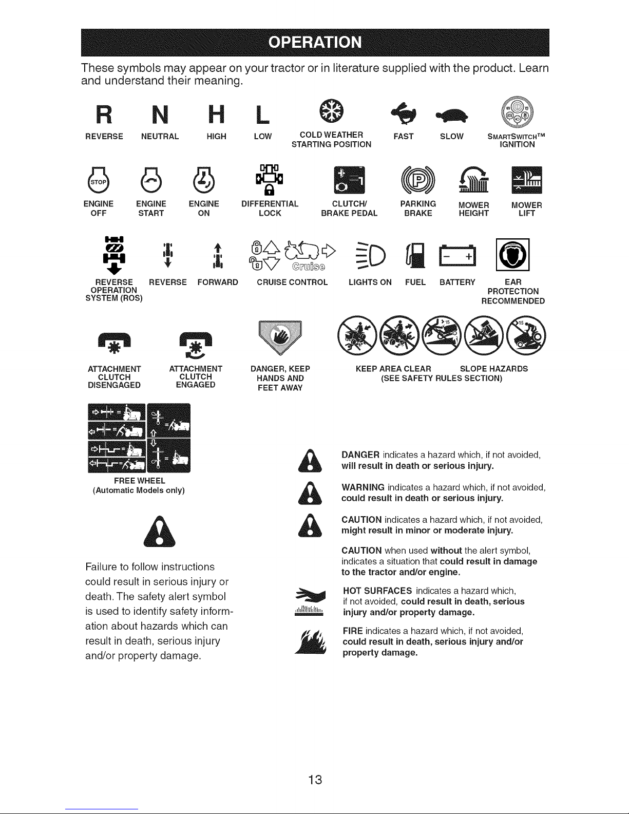
These symbols may appear on your tractor or in literature supplied with the product. Learn
and understand their meaning.
L
REVERSE NEUTRAL HiGH COLD WEATHER
LOW SLOW
STARTING POSiTiON
÷ @
FAST SMARTSWITCHTM
6 6 @ m @
ENGINE ENGINE ENGINE DiFFERENTiAL CLUTCH/ PARKING
OFF START ON LOCK BRAKE PEDAL BRAKE
REVERSE REVERSE FORWARD CRUISECONTROL LIGHTSON
OPERATION
SYSTEM(ROS)
FUEL
@@@@@
ATTACHMENT DANGER, KEEP
CLUTCH HANDS AND
DISENGAGED FEET AWAY
ATTACHMENT
CLUTCH
ENGAGED
KEEPAREACLEAR SLOPE HAZARDS
(SEESAFETY RULESSECTION)
iGNiTiON
MOWER
HEIGHT
a
BATTERY EAR
PROTECTION
RECOMMENDED
MOWER
LiFT
FREE WHEEL
(Automatic Models only)
Failure to follow instructions
could result in serious injury or
death. The safety alert symbol
is used to identify safety inform-
ation about hazards which can
result in death, serious injury
and/or property damage.
DANGER indicates a hazard which, if not avoided,
will result in death or serious injury.
WARNING indicates a hazard which, if not avoided,
could result in death or serious injury.
CAUTION indicates a hazard which, if not avoided,
might result in minor or moderate injury.
CAUTION when used without the alert symbol,
indicates a situation that could result in damage
to the tractor and/or engine.
HOT SURFACES indicates a hazard which,
if not avoided, could result in death, serious
injury and/or property damage.
FIRE indicates a hazard which, if not avoided,
could result in death, serious injury and/or
property damage.
13
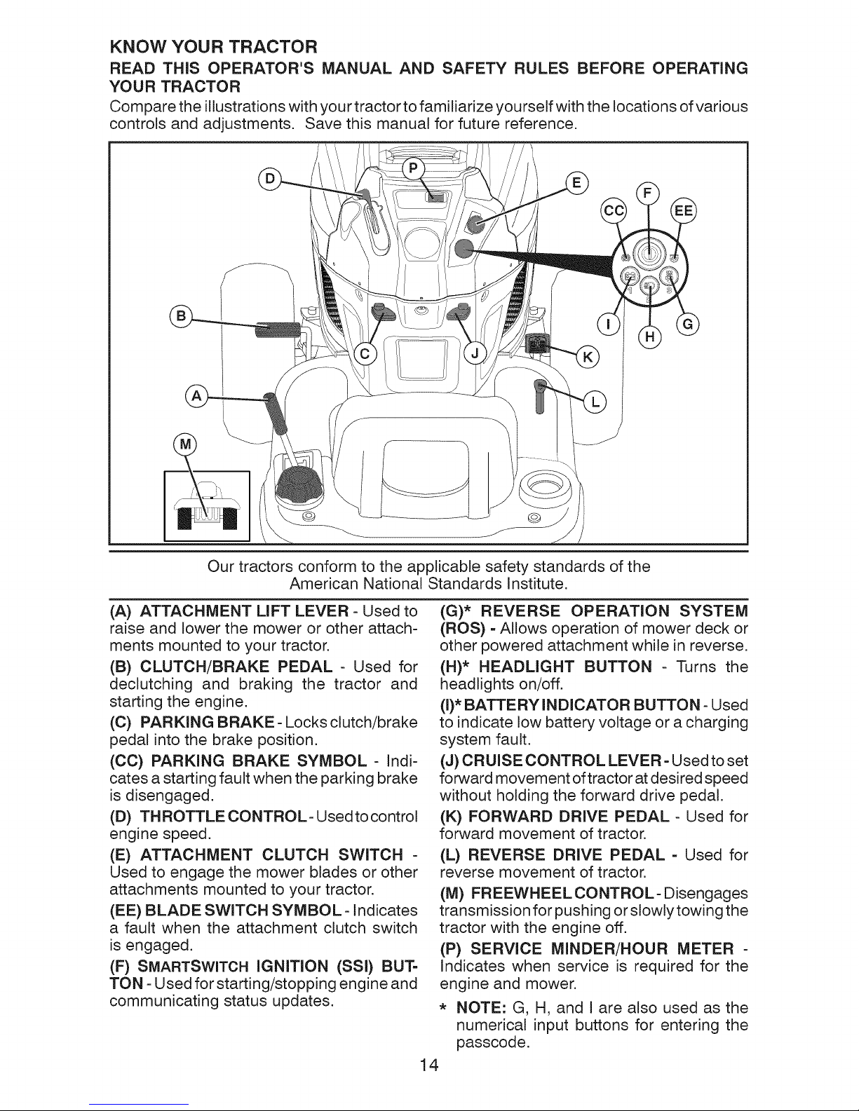
KNOW YOUR TRACTOR
READ THIS OPERATOR'S MANUAL AND SAFETY RULES BEFORE OPERATING
YOUR TRACTOR
Compare the illustrations with your tractor to familiarize yourself with the locations of various
controls and adjustments. Save this manual for future reference.
@ @
Our tractors conform to the applicable safety standards of the
American National Standards Institute.
(A) ATTACHMENT LIFT LEVER - Used to
raise and lower the mower or other attach-
ments mounted to your tractor.
(B) CLUTCH/BRAKE PEDAL - Used for
declutching and braking the tractor and
starting the engine.
(C) PARKING BRAKE- Locks clutch/brake
pedal into the brake position.
(CC) PARKING BRAKE SYMBOL - Indi-
cates a starting fault when the parking brake
is disengaged.
(D) THROTTLE CONTROL- Used to control
engine speed.
(E) ATTACHMENT CLUTCH SWITCH -
Used to engage the mower blades or other
attachments mounted to your tractor.
(EE) BLADE SWITCH SYMBOL-Indicates
a fault when the attachment clutch switch
is engaged.
(F) SMARTSWITCH IGNITION (SSl) BUT-
TON - Used for starting/stopping engine and
communicating status updates.
(G)* REVERSE OPERATION SYSTEM
(ROS) - Allows operation of mower deck or
other powered attachment while in reverse.
(H)* HEADLIGHT BUTTON - Turns the
headlights on/off.
(I)* BATTERY INDICATOR BUTTON - Used
to indicate low battery voltage or a charging
system fault.
(J) CRUISE CONTROL LEVER =Used to set
forward movement of tractor at desired speed
without holding the forward drive pedal.
(K) FORWARD DRIVE PEDAL - Used for
forward movement of tractor.
(L) REVERSE DRIVE PEDAL - Used for
reverse movement of tractor.
(M) FREEWHEEL CONTROL- Disengages
transmission for pushing or slowly towing the
tractor with the engine off.
(P) SERVICE MINDER/HOUR METER -
Indicates when service is required for the
engine and mower.
* NOTE: G, H, and I are also used as the
numerical input buttons for entering the
passcode.
14
The operation of any tractor can result in foreign objects thrown into
the eyes, which can result in severe eye damage. Always wear safety
glasses or eye shields while operating your tractor or performing any
adjustments or repairs. We recommend standard safety glasses or a
wide vision safety mask worn over spectacles.
HOW TO USE YOUR TRACTOR
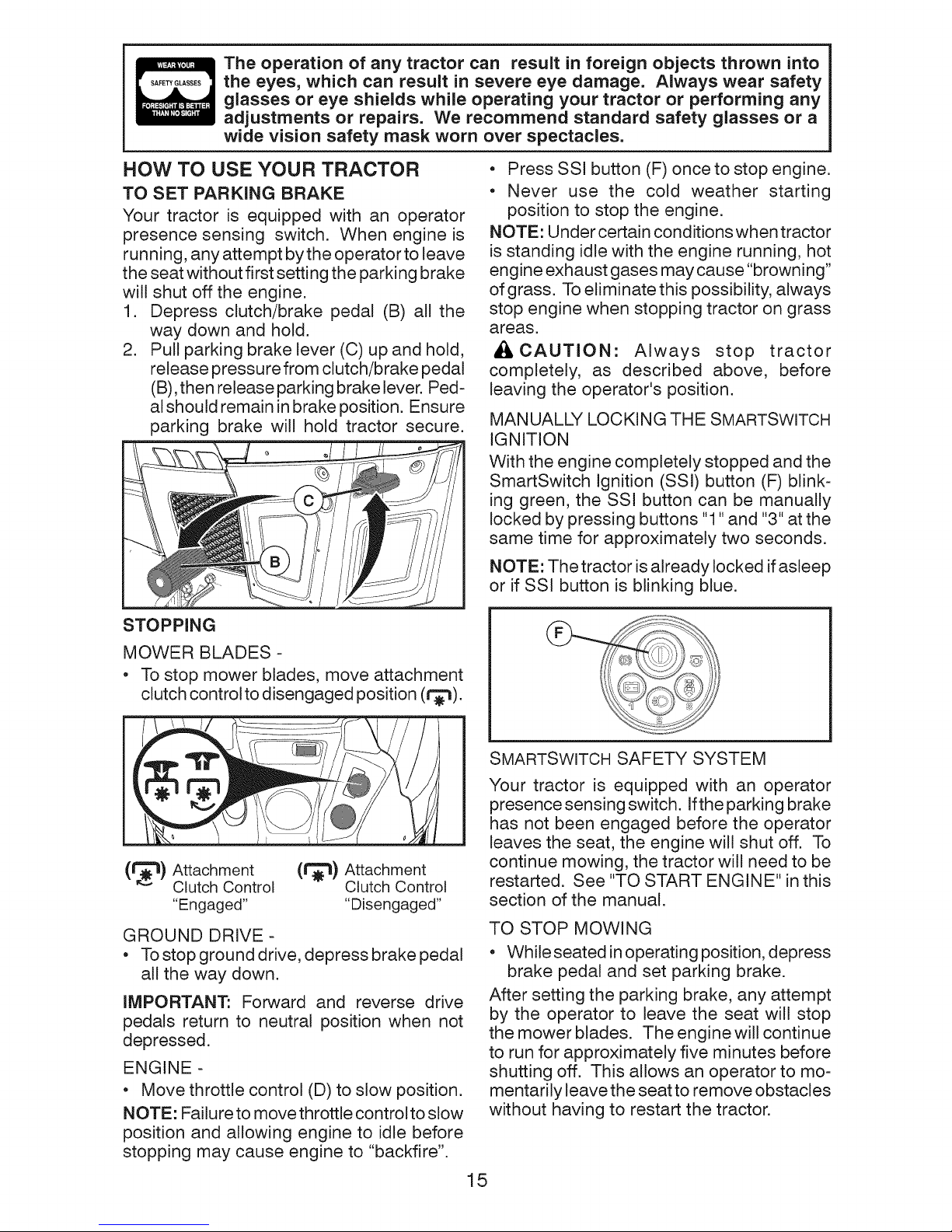
TO SET PARKING BRAKE
Your tractor is equipped with an operator
presence sensing switch. When engine is
running, any attempt by the operator to leave
the seat without first setting the parking brake
will shut off the engine.
1. Depress clutch/brake pedal (B) all the
way down and hold.
2. Pull parking brake lever (C) up and hold,
release pressure from clutch/brake pedal
(B), then release parking brake lever. Ped-
al should remain in brake position. Ensure
parking brake will hold tractor secure.
• Press SSl button (F) once to stop engine.
• Never use the cold weather starting
position to stop the engine.
NOTE: Under certain conditions when tractor
is standing idle with the engine running, hot
engine exhaust gases may cause "browning"
of grass. To eliminate this possibility, always
stop engine when stopping tractor on grass
areas.
_I, CAUTION: Always stop tractor
completely, as described above, before
leaving the operator's position.
MANUALLY LOCKING THE SMARTSWITCH
IGNITION
With the engine completely stopped and the
SmartSwitch Ignition (SSI) button (F) blink-
ing green, the SSI button can be manually
locked by pressing buttons "1" and "3" at the
same time for approximately two seconds.
NOTE: The tractor is already locked ifasleep
or if SSl button is blinking blue.
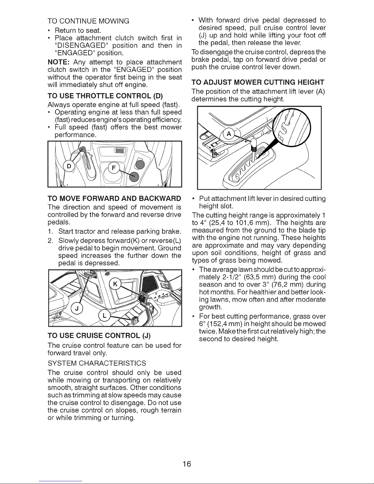
STOPPING
MOWER BLADES -
• To stop mower blades, move attachment
clutch control to disengaged position (r_).
(1_) Attachment (1"_) Attachment
GROUND DRIVE-
• To stop ground drive, depress brake pedal
IMPORTANT: Forward and reverse drive
pedals return to neutral position when not
depressed.
ENGINE -
• Move throttle control (D) to slow position.
NOTE: Failure to move throttle control to stow
position and allowing engine to idle before
stopping may cause engine to "backfire".
Clutch Control Clutch Control
"Engaged .... Disengaged"
all the way down.
SMARTSWITCH SAFETY SYSTEM
Your tractor is equipped with an operator
presence sensing switch. Ifthe parking brake
has not been engaged before the operator
leaves the seat, the engine will shut off. To
continue mowing, the tractor will need to be
restarted. See "TO START ENGINE" in this
section of the manual.
TO STOP MOWING
• While seated in operating position, depress
brake pedal and set parking brake.
After setting the parking brake, any attempt
by the operator to leave the seat will stop
the mower blades. The engine will continue
to run for approximately five minutes before
shutting off. This allows an operator to mo-
mentarily leave the seat to remove obstacles
without having to restart the tractor.
15
TO CONTINUE MOWING
* Return to seat.
, Place attachment clutch switch first in
"DISENGAGED" position and then in
"ENGAGED" position.
NOTE: Any attempt to place attachment
clutch switch in the "ENGAGED" position
without the operator first being in the seat
will immediately shut off engine.
TO USE THROTTLE CONTROL (D)
Always operate engine at full speed (fast).
• Operating engine at less than full speed
(fast) reduces engine's operating efficiency.
• Full speed (fast) offers the best mower
performance.
• With forward drive pedal depressed to
desired speed, pull cruise control lever
(J) up and hold while lifting your foot off
the pedal, then release the lever.
To disengage the cruise control, depress the
brake pedal, tap on forward drive pedal or
push the cruise control lever down.
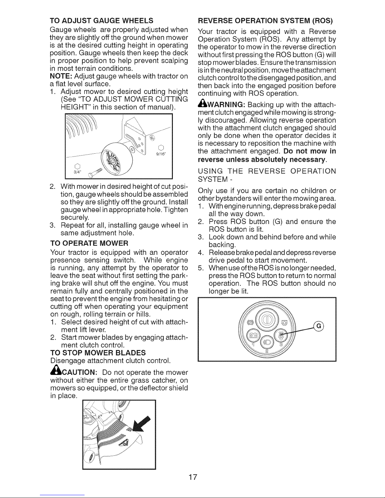
TO ADJUST MOWER CUTTING HEIGHT
The position of the attachment lift lever (A)
determines the cutting height.
TO MOVE FORWARD AND BACKWARD
The direction and speed of movement is
controlled by the forward and reverse drive
pedals.
1. Start tractor and release parking brake.
2. Slowly depress forward(K) or reverse(L)
drive pedal to begin movement. Ground
speed increases the further down the
pedal is depressed.
TO USE CRUISE CONTROL (J)
The cruise control feature can be used for
forward travel only.
SYSTEM CHARACTERISTICS
The cruise control should only be used
while mowing or transporting on relatively
smooth, straight surfaces. Other conditions
such as trimming at slow speeds may cause
the cruise control to disengage. Do not use
the cruise control on slopes, rough terrain
or while trimming or turning.
• Put attachment lift lever in desired cutting
height slot.
The cutting height range is approximately 1
to 4" (25,4 to 101,6 mm). The heights are
measured from the ground to the blade tip
with the engine not running. These heights
are approximate and may vary depending
upon soil conditions, height of grass and
types of grass being mowed.
• The average lawn should be cut to approxi-
mately 2-1/2" (63,5 mm) during the cool
season and to over 3" (76,2 mm) during
hot months. For healthier and better look-
ing lawns, mow often and after moderate
growth.
• For best cutting performance, grass over
6" (152,4 mm) in height should be mowed
twice. Make the first cut relatively high; the
second to desired height.
16
TO ADJUST GAUGE WHEELS
Gauge wheels are properly adjusted when
they are slightly off the ground when mower
is at the desired cutting height in operating
position. Gauge wheels then keep the deck
in proper position to help prevent scalping
in most terrain conditions.
NOTE: Adjust gauge wheels with tractor on
a flat level surface.
1. Adjust mower to desired cutting height
(See "TO ADJUST MOWER CUTTING
HEIGHT" in this section of manual).
©
3/4"
2. With mower in desired height of cut posi-
tion, gauge wheels should be assembled
so they are slightly off the ground. Install
gauge wheel in appropriate hole. Tighten
securely.
3. Repeat for all, installing gauge wheel in
same adjustment hole.
TO OPERATE MOWER
Your tractor is equipped with an operator
presence sensing switch. While engine
is running, any attempt by the operator to
leave the seat without first setting the park-
ing brake will shut off the engine. You must
remain fully and centrally positioned in the
seat to prevent the engine from hesitating or
cutting off when operating your equipment
on rough, rolling terrain or hills.
1. Select desired height of cut with attach-
ment lift lever.
2. Start mower blades by engaging attach-
ment clutch control.
TO STOP MOWER BLADES
Disengage attachment clutch control.
_CAUTION: Do not operate the mower
without either the entire grass catcher, on
mowers so equipped, or the deflector shield
in place.
REVERSE OPERATION SYSTEM (ROS)
Your tractor is equipped with a Reverse
Operation System (ROS). Any attempt by
the operator to mow in the reverse direction
without first pressing the ROS button (G) will
stop mower blades. Ensure the transmission
is in the neutral position, movethe attachment
clutch control to the disengaged position, and
then back into the engaged position before
continuing with ROS operation.
AI_WARNING: Backing up with the attach-
ment clutch engaged while mowing is strong-
ly discouraged. Allowing reverse operation
with the attachment clutch engaged should
only be done when the operator decides it
is necessary to reposition the machine with
the attachment engaged. Do not mow in
reverse unless absolutely necessary.
USING THE REVERSE OPERATION
SYSTEM -
Only use if you are certain no children or
other bystanders will enter the mowing area.
1. With engine running, depress brake pedal
all the way down.
2. Press ROS button (G) and ensure the
ROS button is lit.
3. Look down and behind before and while
backing.
4. Release brake pedal and depress reverse
drive pedal to start movement.
5. When use ofthe ROS is no longer needed,
press the ROS button to return to normal
operation. The ROS button should no
longer be lit.
17
TO OPERATE ON HILLS
HEADLIGHTS
_,WARNING: Do not drive up or down hills
with slopes greater than 15 ° and do not
drive across any slope. Use the slope guide
provided at the back of this manual.
• Choose the slowest speed before starting
up or down hills.
• Avoid stopping orchanging speed on hills.
• If stopping is absolutely necessary, push
brake pedal quickly to brake position and
engage parking brake.
• To restart movement, slowly release park-
ing brake and brake pedal.
• Slowly depress appropriate drive pedal to
slowest setting.
• Make all turns slowly.
TO TRANSPORT
When pushing or towing your tractor, be
sure to disengage transmission by placing
freewheel control in freewheeling position.
Free wheel control is located at the rear
drawbar of tractor.
1. Raise attachment lift to highest position
with attachment lift control.
2. Pull freewheel control out and into the slot
and release so it is held in the disengaged
position.
• Do not push or tow tractor at more than
two (2) mph (3,2 km/h).
• To reengagetransmission, reverse above
procedure.
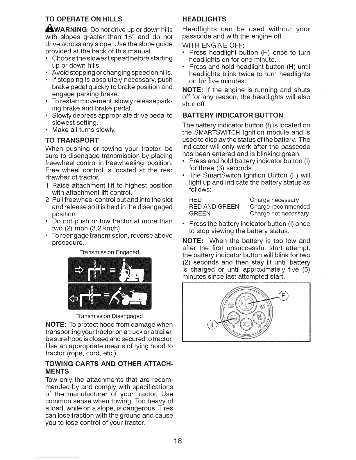
Transmission Engaged
Headlights can be used without your
passcode and with the engine off.
WITH ENGINE OFF:
• Press headlight button (H) once to turn
headlights on for one minute.
• Press and hold headlight button (H) until
headlights blink twice to turn headlights
on for five minutes.
NOTE: If the engine is running and shuts
off for any reason, the headlights will also
shut off.
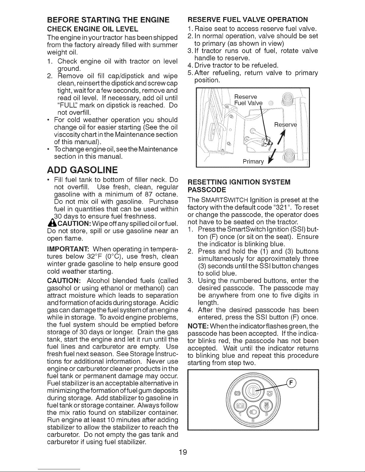
BATTERY INDICATOR BUTTON
The battery indicator button (I) is located on
the SMARTSWITCH Ignition module and is
used to displaythe status of the battery. The
indicator will only work after the passcode
has been entered and is blinking green.
• Press and hold battery indicator button (I)
for three (3) seconds.
• The SmartSwitch Ignition Button (F) will
light up and indicate the battery status as
follows:
RED
RED AND GREEN
GREEN
Charge necessary
Charge recommended
Charge not necessary
• Press the battery indicator button (I) once
to stop viewing the battery status.
NOTE: When the battery is too low and
after the first unsuccessful start attempt,
the battery indicator button will blink for two
(2) seconds and then stay lit until battery
is charged or until approximately five (5)
minutes since last attempted start.
Transmission Disengaged
NOTE: To protect hood from damage when
transporting you r tractor on a truck or a trailer,
be sure hood is closed and secured to tractor.
Use an appropriate means of tying hood to
tractor (rope, cord, etc.).
TOWING CARTS AND OTHER ATTACH-
MENTS
Tow only the attachments that are recom-
mended by and comply with specifications
of the manufacturer of your tractor. Use
common sense when towing. Too heavy of
a load, while on a slope, is dangerous. Tires
can lose traction with the ground and cause
you to lose control of your tractor.
18
BEFORE STARTING THE ENGINE
CHECK ENGINE OiL LEVEL
The engine in your tractor has been shipped
from the factory already filled with summer
weight oil.
1. Check engine oil with tractor on level
ground.
2. Remove oil fill cap/dipstick and wipe
clean, reinsert the dipstick and screw cap
tight, wait for a few seconds, remove and
read oil level. If necessary, add oil until
"FULL' mark on dipstick is reached. Do
not overfill.
* For cold weather operation you should
change oil for easier starting (See the oil
viscosity chart in the Maintenance section
of this manual).
* To change engine oil, seethe Maintenance
section in this manual.
ADD GASOLINE
* Fill fuel tank to bottom of filler neck. Do
not overfill. Use fresh, clean, regular
gasoline with a minimum of 87 octane.
Do not mix oil with gasoline. Purchase
fuel in quantities that can be used within
0 days to ensure fuel freshness.
CAUTION: Wipe off any spilled oil or fuel.
Do not store, spill or use gasoline near an
open flame.
iMPORTANT: When operating in tempera-
tures below 32°F (0°C), use fresh, clean
winter grade gasoline to help ensure good
cold weather starting.
CAUTION: Alcohol blended fuels (called
gasohol or using ethanol or methanol) can
attract moisture which leads to separation
and formation of acids during storage. Acidic
gas can damage the fuel system of an engine
while in storage. To avoid engine problems,
the fuel system should be emptied before
storage of 30 days or longer. Drain the gas
tank, start the engine and let it run until the
fuel lines and carburetor are empty. Use
fresh fuel next season. See Storage Instruc-
tions for additional information. Never use
engine or carburetor cleaner products in the
fuel tank or permanent damage may occur.
Fuel stabilizer is an acceptable alternative in
minimizing the formation of fuel gum deposits
during storage. Add stabilizer to gasoline in
fuel tank or storage container. Always follow
the mix ratio found on stabilizer container.
Run engine at least 10 minutes after adding
stabilizer to allow the stabilizer to reach the
carburetor. Do not empty the gas tank and
carburetor if using fuel stabilizer.
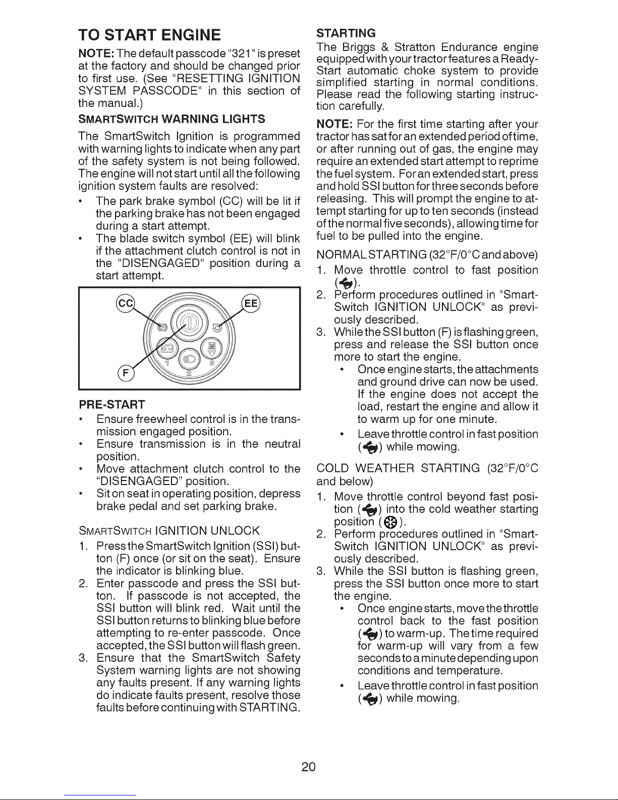
RESERVE FUEL VALVE OPERATION
1. Raise seat to access reserve fue! valve.
2. In normal operation, valve should be set
to primary (as shown in view)
3. If tractor runs out of fuel, rotate valve
handle to reserve.
4. Drive tractor to be refueled.
5.After refueling, return valve to primary
position.
Reserve
Fuel Valve _
Primary
RESETTING IGNITION SYSTEM
PASSCODE
The SMARTSWITCH Ignition is preset at the
factory with the default code "321 ". To reset
or change the passcode, the operator does
not have to be seated on the tractor.
1. Pressthe SmartSwitch Ignition (SSl) but-
ton (F) once (or sit on the seat). Ensure
the indicator is blinking blue.
2. Press and hold the (1) and (3) buttons
simultaneously for approximately three
(3) seconds until the SSl button changes
to solid blue.
3. Using the numbered buttons, enter the
desired passcode. The passcode may
be anywhere from one to five digits in
length.
4. After the desired passcode has been
entered, press the SSl button (F) once.
NOTE: When the indicatorflashes green, the
passcode has been accepted. If the indica-
tor blinks red, the passcode has not been
accepted. Wait until the indicator returns
to blinking blue and repeat this procedure
starting from step two.
19
TO START ENGINE
NOTE: The default passcode "321 "is preset
at the factory and should be changed prior
to first use. (See "RESETTING IGNITION
SYSTEM PASSCODE" in this section of
the manual.)
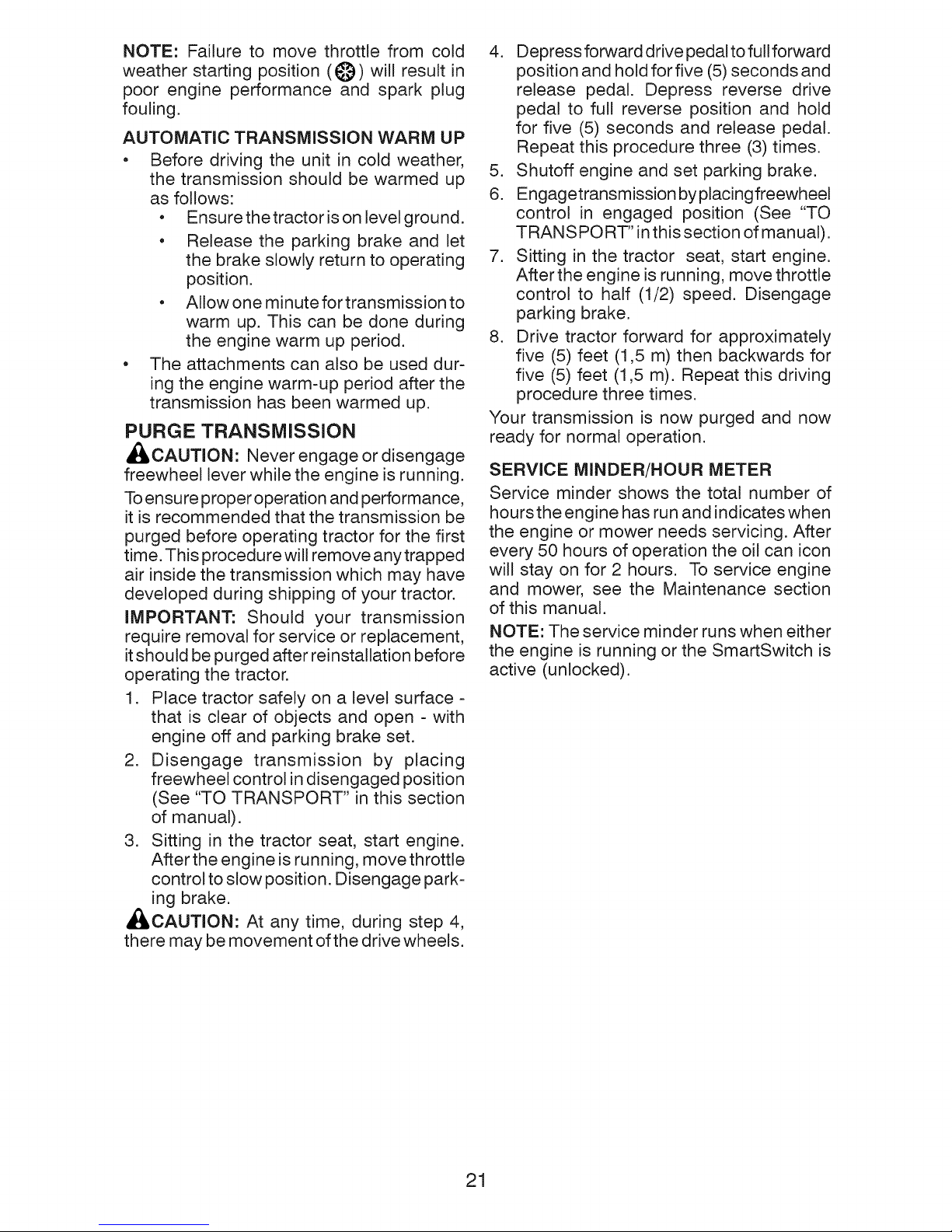
SMARTSWITCH WARNING LIGHTS
The SmartSwitch Ignition is programmed
with warning lights to indicate when any part
of the safety system is not being followed.
The engine will not start until all the following
ignition system faults are resolved:
• The park brake symbol (CC) will be lit if
the parking brake has not been engaged
during a start attempt.
• The blade switch symbol (EE) will blink
if the attachment clutch control is not in
the "DISENGAGED" position during a
start attempt.
PRE-START
• Ensure freewheel control is in the trans-
mission engaged position.
• Ensure transmission is in the neutral
position.
• Move attachment clutch control to the
"DISENGAGED" position.
• Sit on seat in operating position, depress
brake pedal and set parking brake.
SMARTSWITCHIGNITION UNLOCK
1. PresstheSmartSwitch Ignition (SSl) but-
ton (F) once (or sit on the seat). Ensure
the indicator is blinking blue.
2. Enter passcode and press the SSl but-
ton. If passcode is not accepted, the
SSI button will blink red. Wait until the
SSl button returns to blinking blue before
attempting to re-enter passcode. Once
accepted, the SSl button will flash green.
3. Ensure that the SmartSwitch Safety
System warning lights are not showing
any faults present. If any warning lights
do indicate faults present, resolve those
faults before continuing with STARTING.
STARTING
The Briggs & Stratton Endurance engine
equipped with your tractor features a Ready-
Start automatic choke system to provide
simplified starting in normal conditions.
Please read the following starting instruc-
tion carefully.
NOTE: For the first time starting after your
tractor has sat for an extended period oftime,
or after running out of gas, the engine may
require an extended start attempt to reprime
the fuel system. For an extended start, press
and hold SSl button for three seconds before
releasing. This will prompt the engine to at-
tempt starting for up to ten seconds (instead
of the normal five seconds), allowing time for
fuel to be pulled into the engine.
NORMAL STARTING (32°F/0°C and above)
1. Move throttle control to fast position
2. Perform procedures outlined in "Smart-
Switch IGNITION UNLOCK" as previ-
ously described.
3. While the SSl button (F) is flashing green,
press and release the SSI button once
more to start the engine.
• Once engine starts, the attachments
and ground drive can now be used.
If the engine does not accept the
load, restart the engine and allow it
to warm up for one minute.
• Leave throttle control in fast position
(_t_) while mowing.
COLD WEATHER STARTING (32°F/0°C
and below)
1. Move throttle control beyond fast posi-
tion (_) into the cold weather starting
position (I_)).
2. Perform procedures outlined in "Smart-
Switch IGNITION UNLOCK" as previ-
ously described.
3. While the SSI button is flashing green,
press the SSl button once more to start
the engine.
• Once engine starts, movethethrottle
control back to the fast position
(,_) to warm-up. Thetime required
for warm-up will vary from a few
seconds to a minute depending upon
conditions and temperature.
• Leave throttle control in fast position
(,,_) while mowing.
20
NOTE: Failure to move throttle from cold
weather starting position (_)) will result in
poor engine performance and spark plug
fouling.
AUTOMATIC TRANSMISSION WARM UP
Before driving the unit in cold weather,
the transmission should be warmed up
as follows:
• Ensurethetractorisonlevelground.
• Release the parking brake and let
the brake slowly return to operating
position.
• Allowone minutefortransmissionto
warm up. This can be done during
the engine warm up period.
The attachments can also be used dur-
ing the engine warm-up period after the
transmission has been warmed up.
PURGE TRANSMISSION
,_CAUTION: Never engage or disengage
freewheel lever while the engine is running.
To ensure proper operation and performance,
it is recommended that the transmission be
purged before operating tractor for the first
time. This procedure will remove any trapped
air inside the transmission which may have
developed during shipping of your tractor.
IMPORTANT: Should your transmission
require removal for service or replacement,
it should be purged after reinstallation before
operating the tractor.
1. Place tractor safely on a level surface -
that is clear of objects and open - with
engine off and parking brake set.
2. Disengage transmission by placing
freewheel control in disengaged position
(See "TO TRANSPORT" in this section
of manual).
3. Sitting in the tractor seat, start engine.
After the engine is running, move throttle
control to slow position. Disengage park-
ing brake.
_L, CAUTION: At any time, during step 4,
there may be movement of the drive wheels.
4. Depress forward drive pedal to full forward
position and hold forfive (5) seconds and
release pedal. Depress reverse drive
pedal to full reverse position and hold
for five (5) seconds and release pedal.
Repeat this procedure three (3) times.
5. Shutoff engine and set parking brake.
6. Engagetransmissionbyplacingfreewheel
control in engaged position (See "TO
TRANSPORT" in this section of manual).
7. Sitting in the tractor seat, start engine.
After the engine is running, move throttle
control to half (1/2) speed. Disengage
parking brake.
8. Drive tractor forward for approximately
five (5) feet (1,5 m) then backwards for
five (5) feet (1,5 m). Repeat this driving
procedure three times.
Your transmission is now purged and now
ready for normal operation.
SERVICE MINDER/HOUR METER
Service minder shows the total number of
hours the engine has run and indicates when
the engine or mower needs servicing. After
every 50 hours of operation the oil can icon
will stay on for 2 hours. To service engine
and mower, see the Maintenance section
of this manual.
NOTE: The service minder runs when either
the engine is running or the SmartSwitch is
active (unlocked).
21
MOWING TiPS
• DO NOT use tire chains when the mower
housing is attached to tractor.
• Mower should be properly leveled for best
mowing performance. See "TO LEVEL
MOWER HOUSING" in the Service and
Adjustments section of this manual.
• The left hand side of mower should be
used for trimming.
• Drive sothat clippings are discharged onto
the area that has already been cut. Have
the cut area to the right of the tractor. This
will result in a more even distribution of
clippings and more uniform cutting.
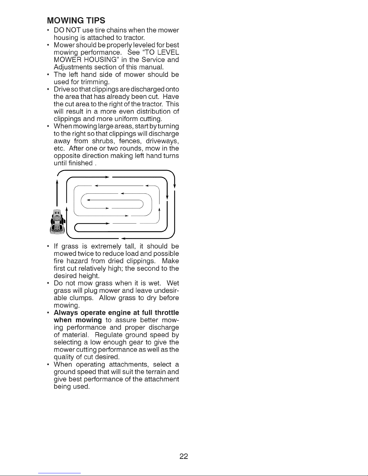
• When mowing large areas, start byturning
to the right so that clippings will discharge
away from shrubs, fences, driveways,
etc. After one or two rounds, mow in the
opposite direction making left hand turns
until finished.
j
(
• If grass is extremely tall, it should be
mowed twice to reduce load and possible
fire hazard from dried clippings. Make
first cut relatively high; the second to the
desired height.
• Do not mow grass when it is wet. Wet
grass will plug mower and leave undesir-
able clumps. Allow grass to dry before
mowing.
• Always operate engine at full throttle
when mowing to assure better mow-
ing performance and proper discharge
of material. Regulate ground speed by
selecting a low enough gear to give the
mower cutting performance as well as the
quality of cut desired.
• When operating attachments, select a
ground speed that will suit the terrain and
give best performance of the attachment
being used.
22
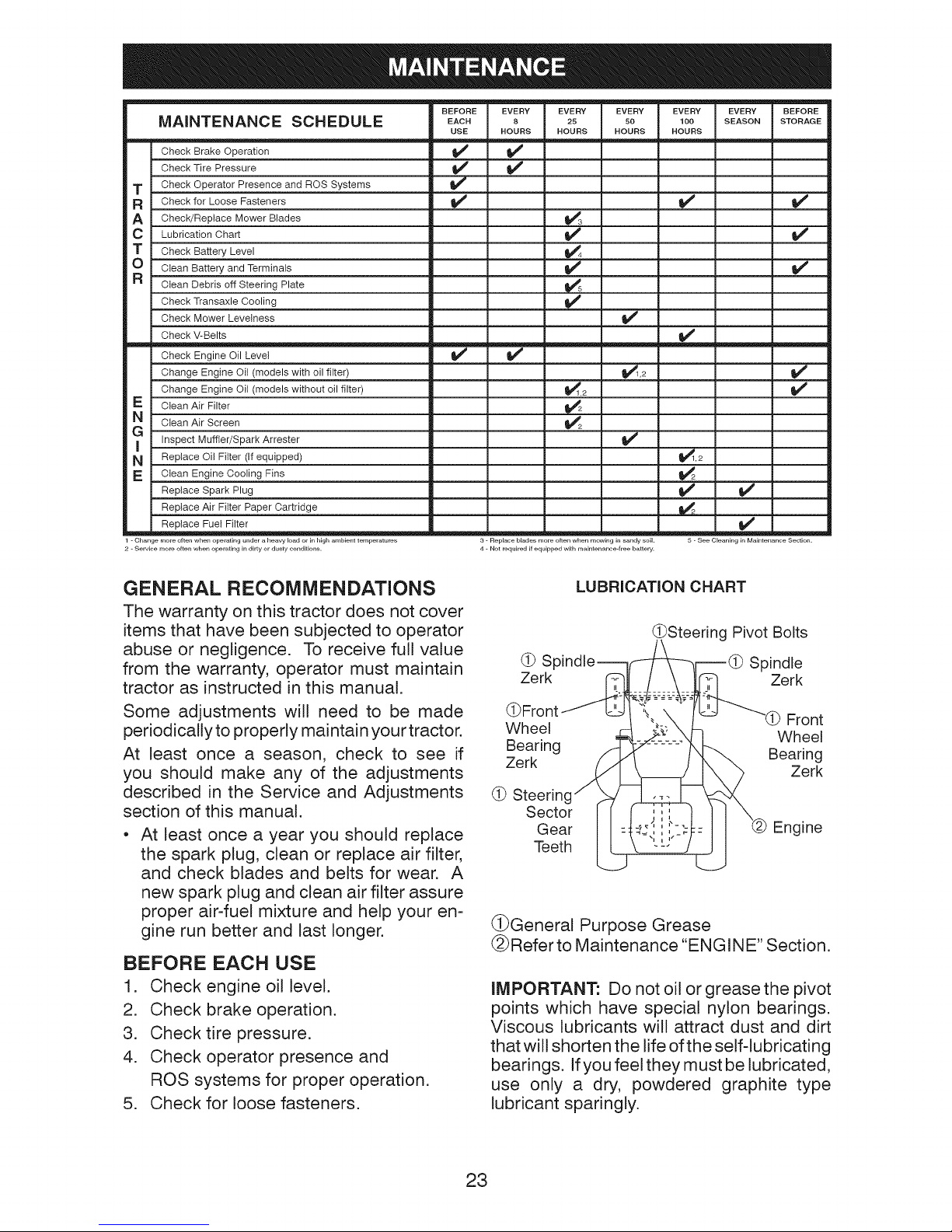
MAINTENANCE SCHEDULE
Check Brake Operation
Check Tire Pressure
T Check Operator Presence and ROS Systems
R Check for Loose Fasteners
A Check/Replace Mower Blades
C Lubrication Chart
T Check Battery Level
O Clean Battery and Terminals
R clean Debris off Steering Plate
Check Transaxle Cooling
Check Mower Levelness
Check V-Belts
Check Engine Oil Level
Change Engine Oil (models with oil filter)
Change Engine Oil (models without oil filter)
E Clean Air Filter
GN clean Air Screen
Inspect Muffler/Spark Arrester
N Replace Oil Filter (If equipped)
Clean Engine Cooling Fins
Replace Spark Plug
Replace Air Filter Paper Cartridge
Replace Fuel Filter
1 - Change more often when operating under a heavy load or in high ambient temperatures
2 - Se_ice more often when operating in dirty or dusty conditions.
BEFORE
EACH
USE
EVERY EVERY EVERY EVERY
8 25 50 100
HOURS HOURS HOURS HOURS
v'
J
v' v'
v' v'
v' v'
v'
v'
v'
v'
_2 v"
v' _"
3 - Replace blades more often when mowing in sandy soil. 5 - See Cleaning in Maintenance Section.
4 - Not required if equipped with maintenance-free battery.
EVERY BEFORE
SEASON STORAGE
GENERAL RECOMMENDATIONS
The warranty on this tractor does not cover
items that have been subjected to operator
abuse or negligence. To receive full value
from the warranty, operator must maintain
tractor as instructed in this manual.
Some adjustments will need to be made
periodically to properly maintain your tractor.
At least once a season, check to see if
you should make any of the adjustments
described in the Service and Adjustments
section of this manual.
At least once a year you should replace
the spark plug, clean or replace air filter,
and check blades and belts for wear. A
new spark plug and clean air filter assure
proper air-fuel mixture and help your en-
gine run better and last longer.
BEFORE EACH USE
1. Check engine oil level.
2. Check brake operation.
3. Check tire pressure.
4. Check operator presence and
ROS systems for proper operation.
5. Check for loose fasteners.
LUBRICATION CHART
(_Steering Pivot Bolts
(_ Sr Spindle
Zerk Zerk
(_ Front
Wheel Wheel
Bearing Bearing
Zerk Zerk
(_ Steerin(
Sector
Gear
Engine
Teeth
(_General Purpose Grease
(_Referto Maintenance ENGINE" Section.
IMPORTANT: Do not oil or grease the pivot
points which have special nylon bearings.
Viscous lubricants will attract dust and dirt
that will shorten the life of the self-lubricating
bearings. Ifyou feel they must be lubricated,
use only a dry, powdered graphite type
lubricant sparingly.
23
TRACTOR
Always observe safety rules when perform-
ing any maintenance.
BRAKE OPERATION
If tractor requires more than 5 feet (1,5 m)
to stop at highest speed in highest gear on
a level, dry concrete or paved surface, then
brake must be serviced. (See "TO CHECK
BRAKE" in the Service and Adjustments
section of this manual).
TIRES
• Maintain proper air pressure in all tires
(See the side of tires for proper PSI.)
• Keep tires free of gasoline, oil, or insect
control chemicals which can harm rubber.
• Avoid stumps, stones, deep ruts, sharp
objects and other hazards that may cause
tire damage.
NOTE: To seal tire punctures and prevent
flat tires due to slow leaks, tire sealant may
be purchased from your local parts dealer.
Tire sealant also prevents tire dry rot and
corrosion.
OPERATOR PRESENCE SYSTEM
AND REVERSE OPERATION SYSTEM
(ROS)
Ensure operator presence and reverse
operation systems are working properly. If
your tractor does not function as described,
repair the problem immediately.
• The engine should not start unless the
parking brake is engaged, and the attach-
ment clutch control is in the disengaged
position.
CHECK OPERATOR PRESENCE SYSTEM
• While the engine is running, any attempt
by the operator to leave the seat without
first setting the parking brake should shut
off the engine.
• With the engine running, the parking
brake engaged, and the attachment clutch
engaged, any attempt by the operator to
leave the seat should shut off the attach-
ment clutch.
• The attachment clutch should never oper-
ate unless the operator is in the seat.
CHECK REVERSE OPERATION (ROS)
SYSTEM
• With the engine running, the SmartSwitch
Ignition (SSI) button (F) solid green, and
the attachment clutch engaged any at-
tempt by the operator to shift in reverse
will disengage the attachment clutch.
With the engine running, the SmartSwitch
Ignition (SSI) button (F) solid green, and
the Reverse Operation System (ROS)
button (G) lit, any attempt by the operator
to shift in reverse should NOT disengage
the attachment clutch.
BLADE CARE
For best results mower blades must be sharp.
Replace worn, bent or damaged blades.
A_ CAUTION: Use only a replacement blade
approved by the manufacturer of your tractor.
Using a blade not approved by the manu-
facturer of your tractor is hazardous, could
damage your tractor and void your warranty.
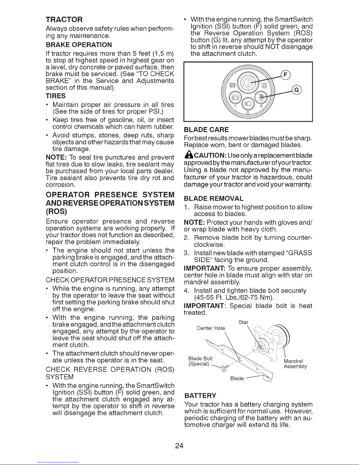
BLADE REMOVAL
1. Raise mower to highest position to allow
access to blades.
NOTE: Protect your hands with gloves and/
or wrap blade with heavy cloth.
2. Remove blade bolt by turning counter-
clockwise.
3. Install new blade with stamped "GRASS
SIDE" facing the ground.
iMPORTANT: To ensure proper assembly,
center hole in blade must align with star on
mandrel assembly.
4. Install and tighten blade bolt securely
(45-55 Ft. Lbs./62-75 Nm).
IMPORTANT: Special blade bolt is heat
treated.
Star
Center Hole
Blade Bolt Mandrel
(Special) -.._j_ Assembly
Blade
BATTERY
Your tractor has a battery charging system
which is sufficient for normal use. However,
periodic charging of the battery with an au-
tomotive charger will extend its life.
24
 Loading...