

Page 1
Operator's Manual
IH II III
Ic FT=M..°I
IIIIIIII
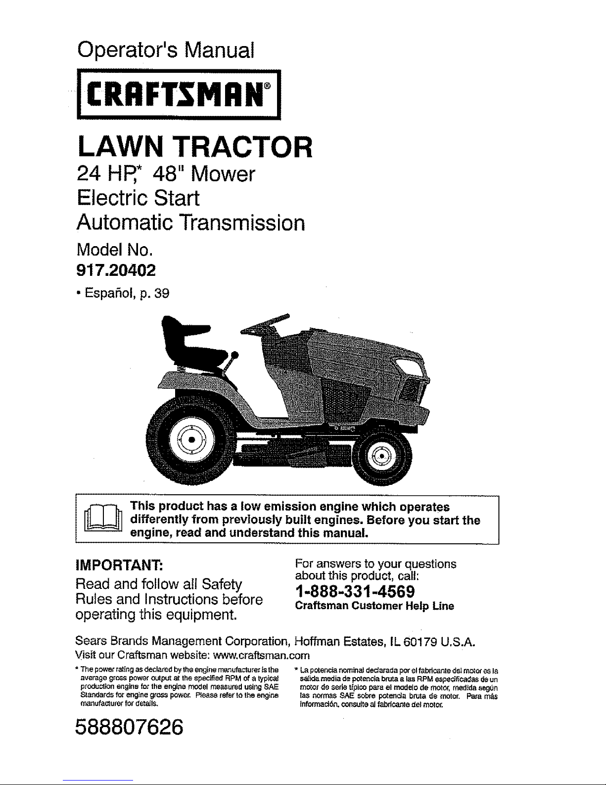
LAWN TRACTOR
24 HR* 48" Mower
ElectricStart
Automatic Transmission
Model No.
917.20402
• EspaSol, p. 39
I_ his product has a low emission engine which operates I
differently from previously built engines. Before you start the
Iengine, read and understand this manual.
IMPORTANT:
Read and follow all Safety
Rules and instructions before
operating this equipment.
For answers to your questions
about this product, call:
1-888-331-4569
Craftsman Customer Help Line
Sears Brands Management Corporation, Hoffman Estates, IL 60179 U.S.A.
Visit our Craftsman website: www.craftsman.com
*Thepowerratingasdeclarodbytheenginemanufacturettsthe * La pctensia nominaI dectarada per el fabdcaote d_ rector e.sla
average gross power output at the specked RPM of a typicaJ saJidamedia de po_encia brF_aa Ias RPM espe_ficadas de un
production engine for the engine model measured using SAE motor de eerie tfpi¢o para e! modelo de motor, medida seg_n
Standards for engine gross power, Please refer to the engine _asnormas SAE sobra p_enda bruta de mOtor, Para m_
manufacturer for detaJls, !nformadbn, con,suiteal fabdcante del mOtor,
588807626
Page 2
Warranty .................................................. 2
Safety Rules ............................................ 3
....Product Specifications ............................. 6
Assembly/Pre-Operation ......................... 7
Operation ................................................. 9
Maintenance Schedule .......................... 18
Maintenance .......................................... 18
Service and Adjustments ....................... 23
Storage .................................................. 33
Troubleshooting ..................................... 34
Sears Service ............... _......... Back Cover
CRAFTSMAN LIMITED WARRANTY
FOR "i'WO YEARS from the date of purchase, all non-expendable parts of this riding equipment are
warranted against defects in material or workmanship, With proof of purchase, a defective non-expendable
part will receive free repair or replacement at option of seller,
Battery Limited Warranty
FOR 90 DAYS from the date of purchase, the battery (an expendabie part) of this riding equipment is
warranted against defects in material or workmanship, With proof of purchase, you will receive a new
battery at no charge. You are responsible for the labor cost of batten./installation,
Additional Limited Warranties
In the following additiona; warranties, you are responsible for the labor cost of part installation after the
second year from the date of purchase.
FOR FIVE YEARS from the date of purchase, the frame of this riding equipment is warranted against any
defects in material or workmanship, With proof of purchase, you will receive a new frame at no charge.
FOR TEN YEARS from the date of purchase, the front axle of this riding equipment is warranted against
any defects in material or workmanship. With proof of purchase, you will receive a new axle at no charge.
FOR AS LONG AS IT IS USED by the odginal owner after the tenth year from the date of purchase, the
cast iron front axle (if equipped) of this riding equipment is warranted against any defects in material or
workmanship, With proof of purchase, you will receive a new cast iron front axle at no charge.
WARRANTY SERVICE
For warranty coverage details to obtain free repair or replacement, visit the web page: www.crafteman.com/
warranty
Product Replacement
If part repair or repiaoement is impossible, you will receive a new riding equipment unit of the Same or
equivalent model.
Warranty Restriction
All warranty coverage is void ff this riding equipment is ever used while providing commercial services or ff
rented to another person.
This warranty covers ONLY defects In material and workmanship, Warranty coverage does NOT
include:
• Expendable parts (except battery) that can wear out from normal use within the warranty period, including
but not limited to blades, spark plugs, belts and air, oil or gas filters.
• Standard maintenance servicing, oil changes or tune-ups.
• Tire replacement or repair caused by punctures from outside objects, such as nails, thorns, stumps, or
glass,
. Tire or wheel replacement or repair resulting from normal wear, accident, or improper operation or
maintenance.
• Repairs necessary because of operator abuse, including but not limited to damage caused by towing
objects beyond the capability of the riding equipment, impacting objects that bend the frame, axle
assembly or crankshaft, or over-speeding the engine,
• Repairsne_essarybecause_f_perat_rneg_igence,inc_udingbutn_tlimitedt_'e(ectrica_andmechanica_
damage caused by improper storage, failure to use the proper grade and amount of engine oil, failure
to keep the deck clear of flammable debris, or failure to maintain the riding equipment according to the
instructions contained in the operator's manual.
• Engine (fuet system) cleaning or repairs caused by fuet determined to be contaminated or oxidized
(stale). In general, fuel should be used within 30 days of its purchase date.
• Normal deterioration and wear of the exterior finishes, or product labeI replacement.
This warranty gives you specific legal rights, and you may also have other rights which vary from stale to state,
Sears Brands Management Corporation, Hoffman Estates, IL 60179
2
Page 3

_DANGER:This cutting machine is capable of amputating hands and feet and
throwing objects. Failure to observe the following safety instructions could result
in serious injury or death,
A(_WARNING: Inordertopreventacciden-
tal starting when setting up, transporting,
adjusting or making repairs, always discon-
nect spark plug wire and place wire where
it cannot contact spark plug.
_t, WARNING: Do not coast down a hill in
neutral, you may lose control of the tractor.
A_,WARNING: Tow only the attachments
that are recommended by and comply with
specifications of the manufacturer of your
tractor. Use common sense when towing.
Operate onty at the lowest possible speed
when ona slope. Tooheavy of a toad,while
on a slope, is dangerous. Tires can lose
traction with the ground and cause you to
lose control of yourtractor.
_L.WARNING: Engine exhaust, some of
its constituents, and certain vehicle compo-
nents contain or emit chemicals known to
the State of California to cause cancer and
birth defects or other reproductive harm.
_ILWARNING: Battery posts,terminals and
related accessories contain lead and lead
compounds, chemicals knownto the State of
California to cause cancer and birth defects
or other reproductive harm. Wash hands
after handling.
1,CHILDREN
_WARNING! CHILDREN CAN BE IN-
JURED BYTHIS EQUIPMENT, TheAmeri-
can Academy of Pediatrics recommends
that children be a minimum of 12 year of
age before operatinga pedestriancontrolled
lawn mower and a minimum of I6 years of
age before operating a riding lawn mower.
J_.WARNING! CHILDREN CAN BE
SERIOUSLY INJURED OR KILLED BY
THIS EQUIPMENT. Carefully read and
follow all of the safety instructions below,
Tragic accidents can occur if the operator
is not alert to the presence of children.
Children are often attracted to the machine
and the mowing activity. Never assume
that children will remain where you last
" saw them.
• Keep children out of the mowing area
and inthewatchfulcare of aresponsible
adult other than the operator.
• Be alert and turn machine off if a child
enters the area.
• Before and while backing, look behind
and down for small children.
• Never carry children, even with the
blades shut off. They may fall off and
be seriously injuredor interfere withsafe
machine operation. Children who have
beengiven rides inthe past maysuddenly
appear inthe mowing area for another
ride and be run over or backed over by
the machine.
• Never allow children to operate the ma-
chine.
• Use extreme caution when approaching
blind corners, shrubs, trees, or other
objects that may block your view of a
child.
II. GENERAL OPERATION
- Read, understand, andfollowallJnstruc-
tions on the machine and inthe manual
before starting.
• Do not put hands or feet near rotating
parts or under the machine. Keep clear
ofthe discharge opening at all times.
- Only allow responsible adults, who are
familiar with the instructions,to operate
the machine.
• Clear the area of objects such as rocks,
toys, wire, etc., which could be picked
up and thrown by the blades.
• Ensure the area is clear of bystanders
beforeoperating. Stop machine ifanyone
enters the area.
• Never carry passengers,
- Do not mow in reverse unless absolutely
necessary. Always lookdown and behind
before and while backing.
o Never direct discharged materialtoward
anyone. Avoid discharging material
against a watt or obstruction. Material
may ricochet back toward the operator.
Stop the blades when crossing gravel
surfaces.
- Do notoperate machine withoutthe entire
grass catcher, discharge chute, orother
safety devices in place and working.
3
Page 4
• Slow down before turning.
• Never leave a running machine unat-
tended. Always turn off blades, set
parking brake, and stop engine before
dismounting. Manually lock ignition
switch.(See "MANUALUx' LOCKING
THE SmartSwitch TM IGNITION" in the
Operation section of this manual).
• Disengage blades when not mowing.
Shut off engine and wait for all parts to
come to a complete stop before cleaning
the machine, removingthe grass catcher,
or unclogging the discharge chute.
• Operate machine only indaylight or good
artificial light.
• Do not operatethe machine while under
the influence of alcohol or drugs.
• Watch for traffic when operating near or
crossing roadways.
• Use extreme caution when loading Or
unloading the machine into a traiJer or
truck.
• Always weareye protectionwhen operat-
ing machine.
• Use ear protectors to avoid damage to
hearing.
• Data indicates that operators, age 60
years and above, are involved in alarge
percentage of riding mower-related inju-
ries. These operators should evaluate
their ability to operate the riding mower
safely enoughto pretectthemselves and
others from serious injury.
• Followthemanufacturer'srecommenda-
tienferwheelweights orcounterweights.
o Keep machine free of grass, leaves or
other debris build-upwhich cantouch hot
exhaust/engine parts and burn. Do not
allow the mower deck to plow leaves or
other debris which can cause build-up
to occur. Clean any oil or fue! spillage
before operating or storing the machine.
Allow machine to cool before storage.
III, SLOPE OPERATION
_ILWARNING! When loading or unloading
this machine, do not exceed the maximum
recommended operation angle of 15°.
Slopes are a major factor related to loss of
control and tip-over accidents, which can
result insevere injury or death. Operation
on all slopes requires extreme caution. If
you cannot back up the slope or ifyou feel
uneasy on it, do not mow it.
• Mow up and down slopes, not across.
• Watch for holes, ruts, bumps, rocks, or
other hidden objects. Uneven terrain
could overturn the machine. Tall grass
can hide obstacles.
• Choose a low ground speed so thatyou
will not have to stop or shift while on the
slope.
° Do not mow on wet grass. Tires may
lose traction. Always keep the machine
in gear when going down slopes.
• Donotshiftto neutral and coast downhill.
• Avoid starting, stopping, or turning on a
slope. Ifthe tires ]osetraction, disengage
the blades and proceed slowly straight
down the slope.
• Keep all movement on the slopes slow
and gradual. Do not make sudden
changes in speed or direction, which
could cause the machine to roll over.
• Use extreme caution while operating
machine with grass catchers or other
attachments; they can affect the stabil-
ity of the machine. Do no use on steep
slopes.
• Do not try to stabilize the machine by
putting your foot on the ground.
• Do not mow near drop-offs, ditches,
or embankments. The machine could
suddenly roll over if a wheel is over the
edge or if the edge caves in.
If machine stops while going uphill,
disengage blades, shift into reverse and
back down slowly.
• Do not turn on slopes unless necessary,
and then, turn slowly and gradually
downhill, if possible.
IV. TOWING
• Towenly witha machine thathasahitch
designed fortowing, Do not attachtowed
equipment except at the hitch point.
• Followthe manufacturer's recommenda-
tionfor weight limitsfor towed equipment
and towing on slopes.
• Never allow children or others in or on
towed equipment.
• Onslopes, the weight ofthe towed equip-
ment may cause loss oftraction andloss
of control.
• Travel slowly and allow extra distance to
stop.
Page 5
V,SERVICE
SAFE HANDLING OF GASOLINE
To avoid personal injury or property dam-
age, use extreme care inhandling gasoline.
Gasoline is extremely flammable and the
vapors are explosive.
• Extinguish all cigarettes, cigars, pipes,
and other sources of ignition.
- Use only approved gasoline container.
• Never remove gas cap or add fuel with
the engine running.
• Allow engine to cool before refueling.
° Never fuel the machine indoors.
• Never storethe machine orfuel container
where there is an open flame, spark, or
pilot light such as on a water heater or
other appliances.
• Never fill containers inside a vehicle or
on atruck or trailer bedwith plastic liner.
Always place containers on the ground
away from your vehicle when filling.
• Remove gas-powered equipment from
the truck or trailer and refuel it on the
ground. Ifthis is not possible, then refuel
such equipmentwith aportablecontainer,
rather than from a gasoline dispenser
nozzle.
- Keep the nozzle in contact with the rim
of the fuel tank or container opening at
all times until fueling is complete. Do not
use a nozzle lock-open device.
• tffuelis spilled on clothing, changecloth-
ing immediately.
• Never overfill fuel tank. Replace gas cap
and tighten securely.
GENERAL SERVICE
• Never operate machine ina closed area.
• Keep all nuts and boltstighttoensurethe
equipment is in safe working condition.
• Nevertamperwith safetydevices. Never
interfere with the intended function of a
safety device or reduce the protection
provided by a safety device. Check there
proper operation regularly, NEVER oper-
ate a machine with a safety device that
does notfunction properly.
• Keep machine free of grass, leaves, or
other debris build-up. Clean oil or fuel
spillage and remove any fuel-soaked
debris. Allow machine to cool before
storing.
• If you strike a foreign object, stop and
inspectthe machine. Repair,ifnecessary,
before restarting.
• Never make any adjustments or repairs
with the engine running,
• Checkgrass catcher components andthe
discharge chute frequently and replace
with manufacturer's recommended parts,
when necessary.
• Mowerbladesaresharp. Wraptheblade
orwear gloves, and use extreme caution
when servicing them.
• Check brakeoperationfrequently. Adjust
and service as required.
• Maintain orreplace safety and instruction
labels, as necessary, -'
Use ear protectors to avoid damage to hearing.
Always wear eye protectionwhen operatingmachine.
5
Page 6
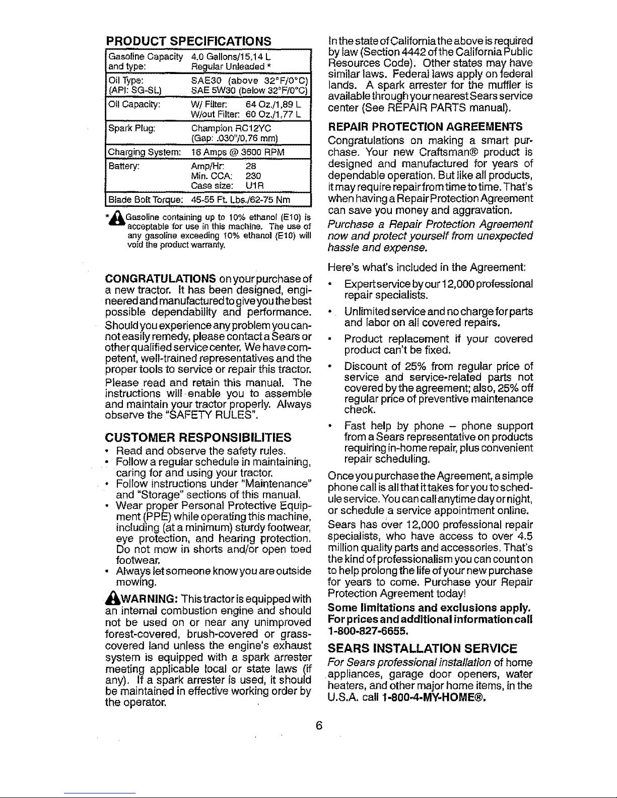
PRODUCT SPECIFICATIONS
Gasoline Capacity 4.0 Gallons/15,14 L
and type: Regular Unleaded *
Oil Type: SAE30 (above 32°F/0°C
(API: SG-SL) BAE 5W30 (below 32°F/0°C
Oil Capacity: WI Filter: 64 Oz./1,89 L
W/out Filter: 60 Oz./1,77 L
Spark Plug: Champion RC12YC
(Gap: .030"/0,76 ram)
16 Amps,@ 3600 RPM
Amp/Hr: 28
Min. OCA: 230
Case size: UIR
45-55 Ft. LbsJ62-75 Nm
Char,,ging System:
Battery:
Blade Bolt Torque:
*_jLGasoline containing up to 10% ethanol (EIO) _s
acceptable for use in this machine. The use of
any gasoline exceeding 10% ethanol (EtO) will
void the product warranty.
CONGRATULATIONS on your purchase of
a new tractor. It has been designed, engi-
neered and manufactured to give you the best
possible dependability and performance.
Should you experience any problem you can-
not easily remedy, please contact a Sears or
other qualified servicecenter. We havecom-
petent, well-trained representatives and the
proper tools to service or repair this tractor.
Please read and retain this manual. The
instructions will enable you to assemble
and maintain your tractor properly. Always
observe the 'SAFETY RULES".
CUSTOMER RESPONSIBILITIES
• Read and observe the safety rules.
• Follow aregular schedule in maintaining,
caring for and using your !ractor.
o Follow instructions under 'Maintenance"
and "Storage" sections of this manual,
• Wear proper Personal Protective Equip-
ment (PPE) while operating this machine,
including(at a minimum) sturdy footwear,
eye protection, and hearing protection,
Do not mow in shorts and/or open toed
footwear,
• Always let someone knowyou areoutside
mowing.
_,WAR NING: This tractor is equipped with
an internal combustion engine and should
not be used on or near any unimproved
forest-covered, brush-covered or grass-
covered land unless the engine's exhaust
system is equipped with a spark arrester
meeting applicable local or state laws (if
any), If a spark arrester is used, it should
be maintained in effective working order by
the operator.
Inthe state ofCalifornia theabove isrequired
bylaw (Section 4442 ofthe California Public
Resources Code). Other states may have
similar laws. Federal laws apply on federal
lands. A spark arrester for the muffler is
availablethroughyour nearestSears service
center (See REPAIR PARTS manual).
REPAIR PROTECTION AGREEMENTS
Congratulations on making a smart pur-
chase. Your new Craftsman@ product is
designed and manufactured for years of
dependable operation. But like all products,
itmay require repairfrom time to time. That's
when having aRepairProtection Agreement
can save you money and aggravation.
Purchase a Repair Protection Agreement
now and protect yourself from unexpected
hassle and expense.
Here's what's included inthe Agreement:
• Expertservice byour 12,000 professionaI
repair specialists.
• Unlimited service andnocharge forparts
and labor on all covered repairs,
Product replacement if your covered
product can't be fixed,
• Discount of 25% from regular price of
service and service-related parts not
covered bythe agreement; also, 25% off
regular price of preventive maintenance
check.
• Fast help by phone - phone support
from aSears representative on products
requiring in-homerepair, plusconvenient
repair scheduling,
Once youpurchasethe Agreement, asimple
phone call isallthat ittakes for you to sched-
uleservice."Youcan callanytime dayornight,
or schedule a service appointment online.
Sears has over 12,000 professional repair
specialists, who have access to over 4.5
million quality parts and accessories, That's
the kindof professionalism you can count on
to help prolong the life ofyour new purchase
for years to come. Purchase your Repair
Protection Agreement today!
Some limitations and exclusions apply.
Forprices andadditional information call
1-800-827-6655.
SEARS INSTALLATION SERVICE
For Sears professional instaflation of home
appliances, garage door openers, water
heaters, and other major home items,in the
U,S.A, call 1-8004-MY-HOME®.
Page 7
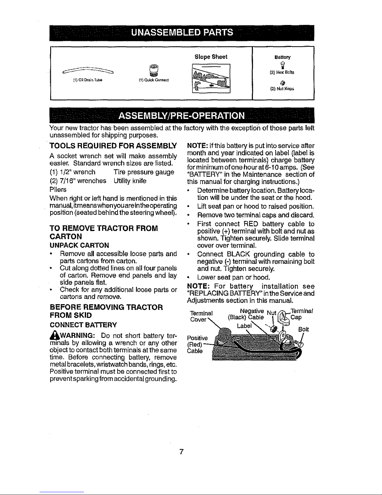
[_) Oil DrainT_e (1} Qu_;k Correct
Slope Sheet Battery
(21 Hex Bolts
12)Nut Keps
Your new tractor has been assembled at thefactory withthe exception of those parts left
unassembled for shipping purposes.
TOOLS REQUIRED FOR ASSEMBLY
A socket wrench set will make assembly
easier. Standard wrench sizes are listed.
(1) 1/2" wrench Tire pressure gauge
(2) 7/16" wrenches UtUityknife
Pliers
When right or left hand ismentioned inthis
manual,itmeanswhenyouareintheoperating
position (seated behind the steering wheel).
TO REMOVE TRACTOR FROM
CARTON
UNPACK CARTON
• Remove all accessible loose parts and
parts cartons from carton,
° Cut along dotted lines on allfour panels
of carton. Remove end panels and lay
side panels flat.
• Check for any additional loose parts or
cartons and remove.
BEFORE REMOVING TRACTOR
FROM SKID
CONNECT BATTERY
_It, WARNING: Do not short battery ter-
minals by allowing a wrench or any other
object to contact both terminals atthe same
time. Before connecting battery, remove
metalbracelets, wristwatch bands, rings,etc.
Positive terminal must be connected first to
prevent sparking from accidental grounding.
NOTE: Ifthis battery isput intoservice after
month andyear indicated on label (label is
located between terminals) charge battery
forminimum ofonehourat6-1Oamps. (See
"BATTERY" in the Maintenance section of
this manual for charging instructions.)
• Determine batterylocation, Batteryloca-
tion willbe under the seat or the hood.
• Lift seat pan or hood to raised position.
• Remove two terminal caps and discard.
• First connect RED battery cable to
positive (+) terminal with bolt and nut as
shown. Tighten securely. Slide terminal
cover over terminal.
• Connect BLACK grounding cable to
negative (-) terminal with remaining bolt
and nut.Tighten securely.
- Lower seat pan or hood,
NOTE: For battery installation see
"REPLACING BATTERY" inthe Service and
Adjustments section in this manual.
Terminal Negative Terminal
Cover\_ Cap
BOlt
Positive
Cable
Page 8
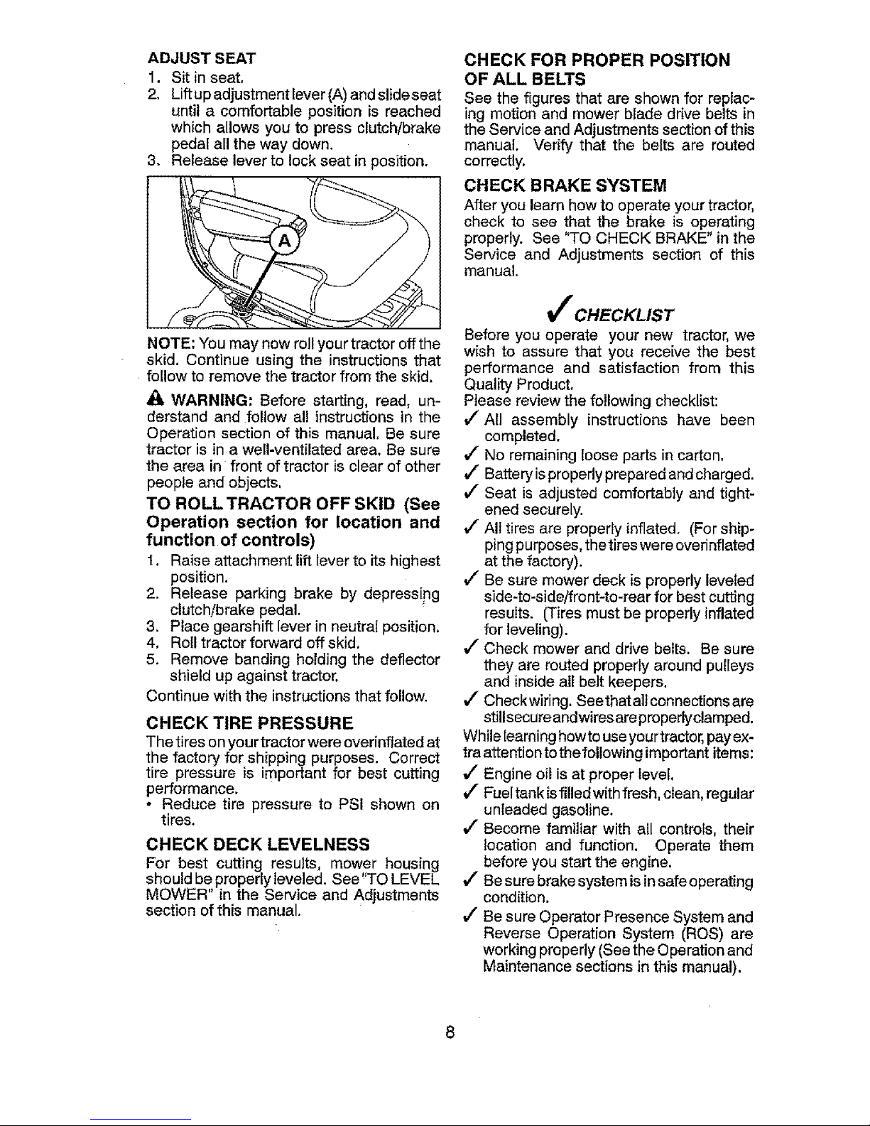
ADJUST SEAT
1. Sit inseat,
2. Liftup adjustment lever (A)and slideseat
until a comfortable position is reached
which allows you to press clutch/brake
pedal all the way down.
3. Release lever to lock seat in position.
NOTE: You may now rollyour tractor off the
skid. Continue using the instructions that
follow to remove the tractor from the skid.
WARNING: Before starting, read, un-
derstand and follow al! instructions in the
Operation section of this manual, Be sure
tractor is ina well-ventilated area. Be sure
the area in front of tractor is clear of other
people and objects,
TO ROLL TRACTOR OFF SKID (See
Operation section for location and
function of controls)
1. Raise attachment lift leverto its highest
position.
2. Release parking brake by depressing
clutch/brake pedal.
3. Place gearshift lever in neutral position.
4. Roll tractor forward off skid.
5. Remove banding holding the deflector
shield up against tractor.
Continue with the instructions that follow.
CHECK TIRE PRESSURE
Thetires onyourtractorwere overinflatedat
the factory for shipping purposes. Correct
tire pressure is important for best cutting
performance.
• Reduce tire pressure to PSI shown on
tires.
CHECK DECK LEVELNESS
For best cutting results, mower housing
should be properly leveled. See*'TO LEVEL
MOWER' in the Service and Adjustments
section of this manual.
CHECK FOR PROPER POSITION
OF ALL BELTS
See the figures that are shown for replac-
ing motion and mower blade drive belts in
the Service and Adjustments section of this
manual. Verify that the belts are routed
correctly.
CHECK BRAKE SYSTEM
After you learn how to operate yourtractor,
check to see that the brake is operating
properly. See "TO CHECK BRAKE" inthe
Service and Adjustments section of this
manual.
t_ CHECKLIST
Before you operate your new tractor, we
wish to assure that you receive the best
performance and satisfaction from this
Quality Product,
Please review the following checklist:
I/All assembly instructions have been
completed,
J" No remaining loose parts in carton,
vF Battery isproperly prepared andcharged.
J" Seat is adjusted comfortably and tight-
ened securely.
_/"All tires are properly inflated. (For ship-
ping purposes, thetires were overinflated
at the factory).
_/"Be sure mower deck is properly leveled
side-to-side/front-to-rear for best cutting
results. (Tires must be properly inflated
for leveling).
J" Check mower and drive belts. Be sure
they are routed properly around pulleys
and inside all belt keepers.
J Check wiring. Seethata]t connections are
stillsecure andwires areproperlyclamped.
While learninghowto useyourtractor,payex-
traattention tothefollowing important items:
!/Engine oil is at proper level.
_/" Fueltank isfilled with fresh, clean, regular
unleaded gasoline.
J" Become familiar with all controls, their
location and function. Operate them
before you start the engine.
J" Besure brake system isinsafe operating
condition.
_/Be sure Operator Presence System and
Reverse Operation System (ROS) are
working properly (Seethe Operation and
Maintenance sections in this manual).
8
Page 9
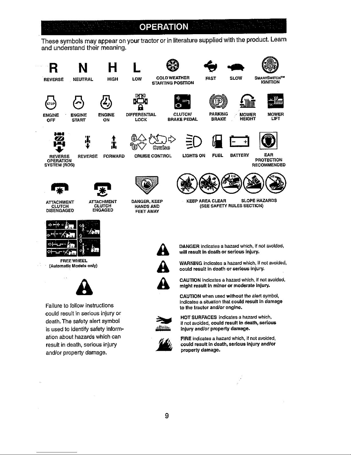
These symbols may appear on your tractor or in literature supplied with the product. Learn
and understand their meaning.
.....R N H
REVERSE NEUTRAL HIGH SLOW SMARISwF_I_ TM
IGNmON
L
LOW COLD WEATHER FAST
STARTING POSITION
ENGtNE ENGINE ENGINE DIFFERENTIAL
OFF START ON LOCK
CLUTCW MOWER
BRAKE PEDAL LtFT
PARKING - MOWER
BRAKE HEIGHT
I.IH
REVERSE
OPERATION
SYSTEM (ROS)
REVERSE FORWARD
CRUISE CONTROL LIGHTS ON FUEL BATTERY EAR
PROTECTION
RECOMMENDED
ATrACHMENT ATTACHMENT DANGER, KEEP
CLUTCH CLUTCH HANDS AND
DISENGAGED ENGAGED FEET AWAY
KEEP AREA CLEAR SLOPE HAZARDS
{SEE SAFETY RULES SECTION)
FREEWHEEL
(Automatic Models only}
Failure to follow instructions
couldresult inserious injuryor
death.The safety alert symbol
is used to identify safety inform-
ation about hazards which can
resultin death, serious injury
and/or property damage.
&
&
&
DANGER indicatesa hazard which, ifnot avoided,
will result in death or serious injury.
WARNING indicates a hazard which, if not avoided,
could result in death or serious injury.
CAUTION indicates a hazard which, if not avoided.
might result In minor or moderate Injury.
CAUTION when used without the alert symbol,
indicatesa situation thatcould result In damage
to the trastor and/or engine.
HOT SURFACES indicates a hazard which,
_fnot avoided, could result in death,serious
injury and/or property damage.
FIRE indicates a hazard which, it not avoided,
could result in death, serious injury and/or
property damage.
Page 10
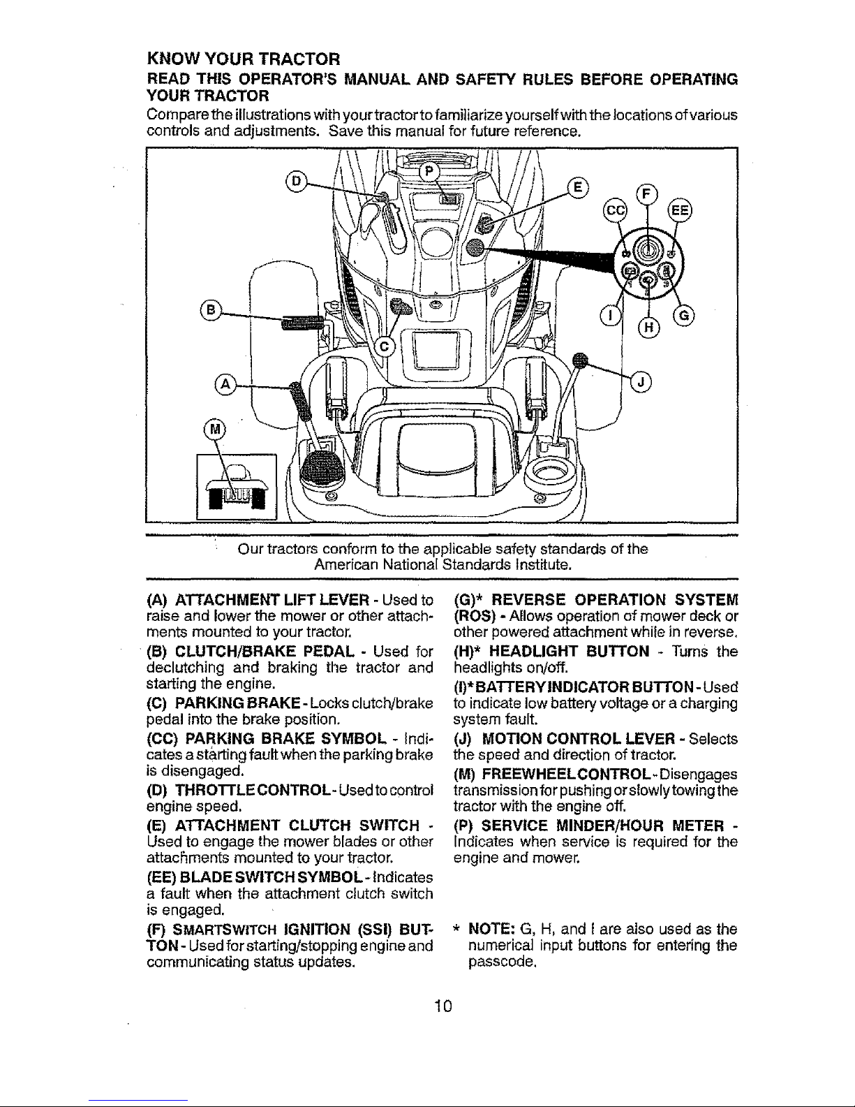
KNOW YOUR TRACTOR
READ THIS OPERATOR'S MANUAL AND SAFETY RULES BEFORE OPERATING
YOUR TRACTOR
Compare the illustrationswithyourtractorto familiarize yourself with the locations ofvarious
controls and adjustments. Save this manual for future reference.
Our tractors conform to the applicable safety standards of the
Amedcan National Standards Institute.
(A) ATTACHMENT LIFT LEVER - Used to
raise and lower the mower or other attach-
ments mounted to your tractor.
(B) CLUTCH/BRAKE PEDAL - Used for
declutching and braking the tractor and
starting the engine.
(C) PARKING BRAKE- Locks clutch/brake
pedal into the brake position.
(CC) PARKING BRAKE SYMBOL - Indi-
cates astarting fault whenthe parking brake
is disengaged,
(D) THROTTLE CONTROL- Usedto control
engine speed.
(E) ATTACHMENT CLUTCH SWITCH °
Used to engage the mower blades or other
attachments mounted to your tractor.
(EE) BLADE SWITCH SYMBOL- indicates
a fault when the attachment dutch switch
isengaged.
(F) SMARTSWITCH IGNITION (SSI) BUT-
TON- Usedfor starting/stopping engine and
communicating status updates,
(G)* REVERSE OPERATION SYSTEM
(ROS) - Allows operation of mower deck or
other powered attachment while in reverse,
(H)* HEADLIGHT BUTTON - Turns the
headlights on/off.
(i)*BATTERYINDICATOR BUTTON- Used
to indicate lowbattery voltage or a charging
system fault.
(J) MOTION CONTROL LEVER - Selects
the speed and direction oftractor.
(M) FREEWHEELCONTROL. Disengages
transmission for pushing or slowlytowing the
tractor with the engine off.
(P) SERVICE MINDER/HOUR METER -
Indicates when service is required for the
engine and mower.
* NOTE: G, H, and I are also used as the
numerical input buttons for entering the
passcode,
10
Page 11
The operation of any tractor can result in foreign objects thrown into
the eyes, which can result in severe eye damage. Always wear safety
glasses or eye shields while operating your tractor oFperforming any
adjustments or repairs. We recommend standard safety glasses or a
wide vision safety mask worn over spectacles.
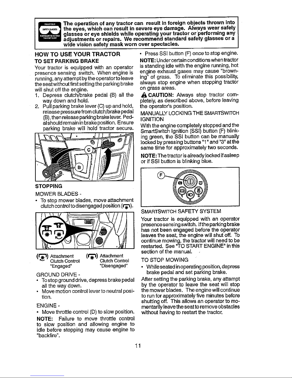
HOW TO USE YOUR TRACTOR
TO SET PARKING BRAKE
Your tractor is equipped with an operator
presence sensing switch. When engine is
running, anyattempt bythe operator to leave
theseatwithout first setting the parking brake
will shut off the engine.
1. Depress clutch/brake pedal (B) all the
way down and hold.
2. Pull parking brake lever (C) up and hold,
release pressure from clutch/brake pedal
(B),then releaseparking brakelever. Ped-
alshould remain inbrake position. Ensure
parking brake will hold tractor secure.
STOPPING
MOWER BLADES -
o Tostopmower blades, moveattachment
clutchcontroltodisengaged position(t_'t).
(t_) Attachment (1"_) A_chment
ClutchControl ClutchControl
"Engaged" "Disengaged'!
GROUND DRIVE -
• Tostop ground drive, depress brake pedal
all the way down.
• Move motion control leverto neutral posi-
tion.
ENGINE -
• Move throttle control (D)to slow position.
NOTE: Failure to move throttle control
to slow position and allowing engine to
idle before stopping may cause engine to
"backfire".
• Press SSl button (F) once to stop engine.
NOTE: Under certain conditions whentractor
is standing idle with the engine running, hot
engine exhaust gases may cause "brown-
ing" of grass. To eliminate this possibility,
always stop engine when stopping tractor
on grass areas.
CAUTION: Always stop tractor com-
pletely, as described above, before leaving
the operator's position.
MANUALLY LOCKINGTHE SMARTSWlTCH
IGNITION
With the engine completely stopped and the
SmartSwitch Ignition (SSI) button (F) blink-
ing green, the SSI button can be manually
locked bypressing buttons "1" and "3"atthe
same time for approximately two seconds,
NOTE: Thetractor isalready locked ffasleep
or if SSI button is blinking blue.
SMARTSWITCHSAFETY SYSTEM
Your tractor is equipped with an operator
presencesensing switch, tfthe parkingbrake
has not been engaged before the operator
leaves the seat, the engine will shut off. To
continuemowing, the tractor willneed to be
restarted. See "TO START ENGINE" in this
section of the manual.
TO STOP MOWING
• Whileseated inoperating position,depress
brake pedal and set parking brake,
After setting the parking brake, any attempt
by the operator to leave the seat will stop
the mowerblades. The engine will continue
to run for approximately five minutes before
shutting off. This allows an operator to mo-
mentarily leavethe seatto remove obstacles
without having to restart the tractor.
11
Page 12
TOCONTINUEMOWING
• Returntoseat,
• Placeattachmentclutchswitchfirstin
"DISENGAGED"positionandthenin
"ENGAGED"position.
NOTE:Anyattempttoplaceattachment
....clutchswitchinthe"ENGAGED"position
withouttheoperatorfirstbeingin the seat
will immediately shut off engine.
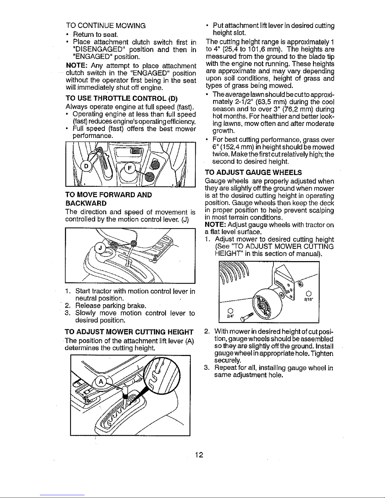
TO USE THROTTLE CONTROL (D)
Always operate engine at full speed (fast).
• Operating engine at less than full speed
(fast)reducesengine'soperating efficiency.
• Full speed (fast) offers the best mower
performance.
TO MOVE FORWARD AND
BACKWARD
The direction and speed of movement is
controlled by the motion control lever. (J)
• Put attachment lift lever in desired cutting
height slot,
The cutting height range is approximately 1
to 4" (25,4 to 101,6 mm). The heights are
measured from the ground to the blade tip
with the engine not running. These heights
are approximate and may vary depending
upon soil conditions, height of grass and
types of grass being mowed.
• Theaverage lawn should becutto approxi-
mately 2-1/2" (63,5 mm) during the cool
season and to over 3" (76,2 mm) during
hot months. For healthier and better look-
ing lawns, mow often and after moderate
growth.
• For best cutting performance, grass over
6" (t52,4 ram) inheight should be mowed
twice, Makethe first cut relatively high;the
second to desired height.
TO ADJUST GAUGE WHEELS
Gauge wheels are properly adjusted when
they are slightly offthe ground when mower
is at the desired cutting height in operating
position. Gauge wheels then keep the deck
in proper position to help prevent scalping
in most terrain conditions.
NOTE: Adjust gauge wheels with tractor on
a flat level surface.
1. Adjust mower to desired cutting height
(See "TO ADJUST MOWER CUTTING
HEIGHT" in this section of manual).
1. Start tractor with motion control lever in
neutral position.
2, Release parking brake.
3. Slowly move motion control lever to
desired position,
TO ADJUST MOWER CUTTING HEIGHT
The positionof the attachment liftlever(A)
determines the cuttingheight.
2. With mower in desired height of cut posi-
tion, gauge whee|s should be assembled
so they are slightly off the ground, install
gauge wheel in appropriate hole. Tighten
securely.
3. Repeat for all, installing gauge wheel in
same adjustment hole.
I2
Page 13
TO OPERATE MOWER
Your tractor is equipped with an operator
presence sensing switch. While engine
is running, any attempt by the operator to
leave the seat without first setting the park-
ing brake will shut off the engine. You must
remain fully and centrally positioned in the
Seatto prevent the engine from hesitating or
cutting off when operating your equipment
on rough, rolling terrain or hills.
1, Select desired height of cut with attach-
merit lift lever.
2, Start mower blades by engaging attach-
ment clutch control,
TO STOP MOWER BLADES
Disengage attachment clutch control.
_I_CAUTION: Do not operate the mower
without either the entire grass catcher, on
mowers so equipped, orthe deflector shield
in place,
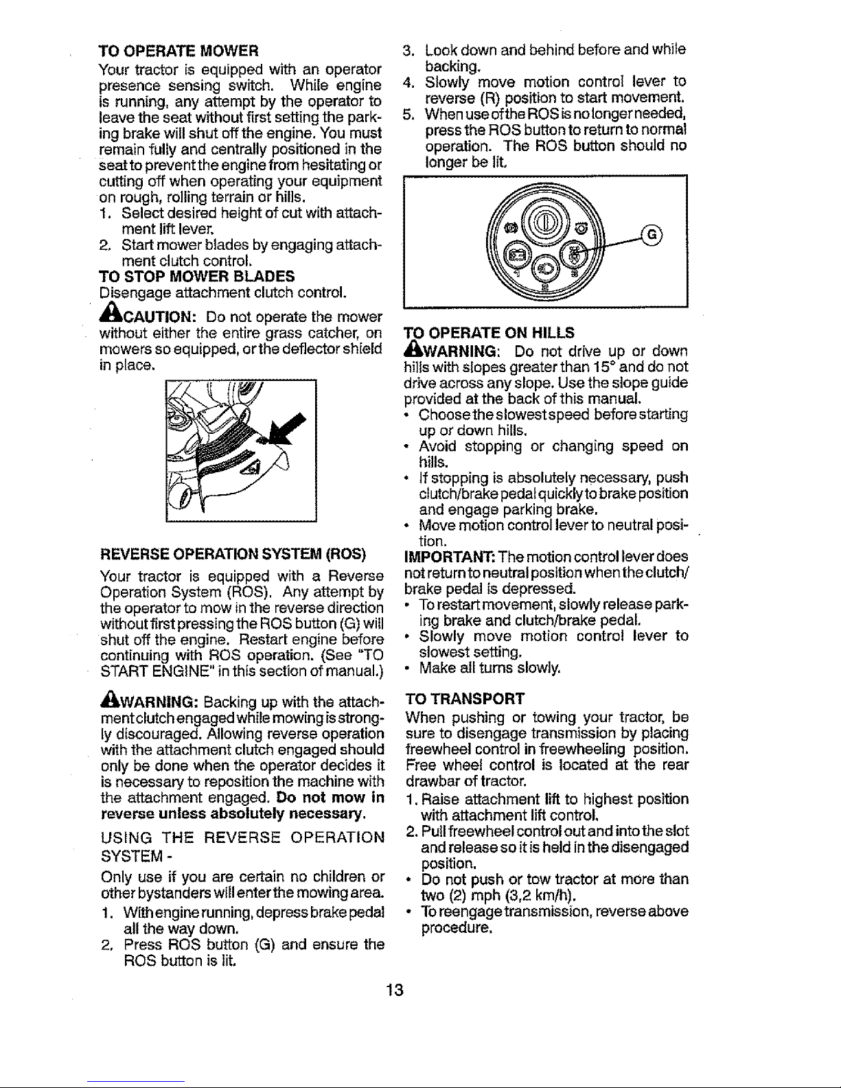
REVERSE OPERATIONSYSTEM (ROS)
Your tractor is equipped with a Reverse
Operation System (ROS), Any attempt by
the operator to mow in the reverse direction
without first pressing the ROS button (G)will
shut off the engine. Restart engine before
continuing with ROS operation. (See "TO
START ENGINE" in this section of manual.)
_ILWARNING: Backing up with the attach-
ment clutchengaged whilemowing isstrong-
[ydiscouraged, Allowing reverse operation
with the attachment clutch engaged should
only be done when the operator decides it
is necessary to reposition the machine with
the attachment engaged. Do not mow in
reverse unless absolutely necessary.
USING THE REVERSE OPERATION
SYSTEM -
Only use if you are certain no children or
other bystanders willenter the mowing area.
1, With engine running, depress brakepedal
all the way down,
2, Press ROS button (G) and ensure the
ROS button is lit,
3. Look down and behind before and while
backing.
4. Slowly move motion control lever to
reverse (R) position to start movement.
5, When useofthe ROSisnolonger needed,
press the ROS button toreturn to normal
operation. The ROS button should no
longer be lit.
TO OPERATE ON HILLS
_I_WARNING: Do not drive up or down
hi]Iswith slopes greater than 15° and do not
drive across any slope, Use theslope guide
provided at the back of this manual.
* Choosethe slowest speed before starting
up or down hills,
o Avoid stopping or changing speed on
hills.
. If stopping isabsolutely necessary, push
clutch/brake pedalquicklyto brake position
and engage parking brake.
- Move motion control lever to neutral posi-
tion.
IMPORTANT: The motion control lever does
not returnto neutral positionwhenthe clutch/
brake pedal is depressed.
. Torestart movement, slowly release park-
ing brake and clutch!brake pedal
. Slowly move motion control lever to
slowest setting,
* Make all turns slowly,
TO TRANSPORT
When pushing or towing your tractor, be
sure to disengage transmission by placing
freewheel control in freewheeling position,
Free wheel control is located at the rear
drawbar of tractor.
1, Raise attachment lift to highest position
with attachment lift control,
2. Pullfreewheel control out and into the slot
andrelease soit isheld inthe disengaged
position.
* Do not push or tow tractor at more than
two (2) mph (3,2 km/h).
- Toreengagetransmission, reverse above
procedure.
13
Page 14
Transmission Engaged
Transmission Disengaged
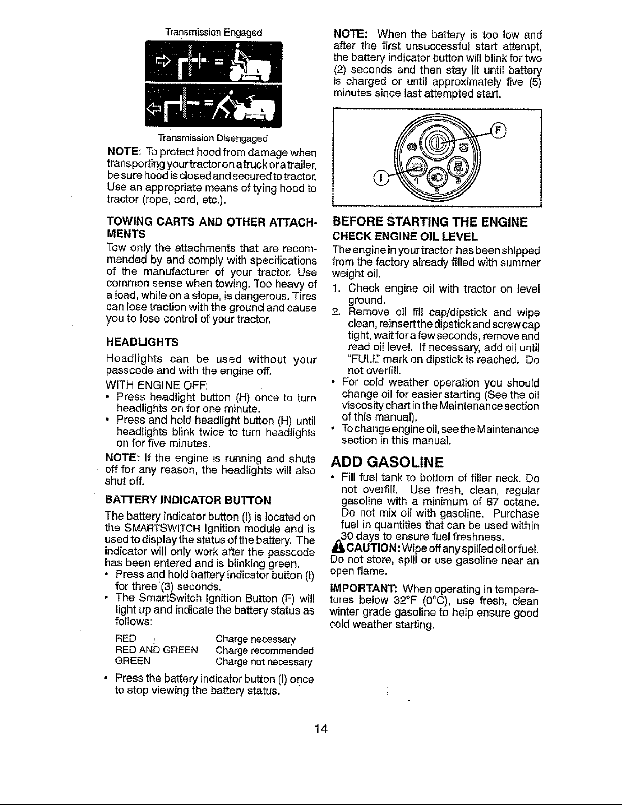
NOTE: When the battery is too low and
after the first unsuccessful start attempt,
the battery indicator button will blink for two
(2) seconds and then stay tit until battery
is charged or until approximately five (5)
minutes since last attempted start.
NOTE: Toprotect hood from damage when
transporting yourtractoron atruck oratrailer,
be surehood isclosed and secured totractor.
Use an appropriate means of tying hood to
tractor (rope, cord, etc.),
TOWING CARTS AND OTHER ATTACH-
MENTS
Tow on[y the attachments that are recom-
mended by and comply with specifications
of the manufacturer of your tractor. Use
common sense when towing. Too heavy of
a load, while on a slope, is dangerous. Tires
can lose traction with the ground and cause
you to lose control of your tractor.
HEADLIGHTS
Headlights can be used without your
passcode and with the engine off.
WITH ENGINE OFF:
• Press headlight button (H) once to turn
headlights on for one minute.
• Press and hold headlight button (H) until
headlights blink twice to turn headlights
on for five minutes.
NOTE: If the engine is running and shuts
off for any reason, the headlights will also
shut off.
BATTERY INDICATOR BUTTON
The batter>, indicator button (!) is located on
the SMARTSWITCH ignition module and is
used to display the status ofthe battery. The
indicator will only work after the passcode
has been entered and is blinking green.
• Press and hold battery indicator button (t)
for three'(3) seconds.
• The SmartSwitch Ignition Button (F) will
light up and indicate the battery status as
follows:
RED _ Charge necessary
RED AND GREEN Charge recommended
GREEN Charge not necessary
Press the battery indicator button (1)once
to stop viewing the battery status,
BEFORE STARTING THE ENGINE
CHECK ENGINE OIL LEVEL
The engine inyourtractor has been shipped
from the factory already filled with summer
weight oil.
1. Check engine oil with tractor on level
ground.
2. Remove oil fill cap/dipstick and wipe
clean,reinsertthe dipstick and screwcap
tight,wait for afewseconds, remove and
read oil level. If necessary, add oil until
"FULE'mark on dipstick is reached. Do
not overfill.
• For cold weather operation you should
change oil for easier starting (Seethe oil
viscosity chart inthe Maintenance section
of this manual).
• Tochangeengine oil, seethe Maintenance
section inthis manual.
ADD GASOLINE
• Fill fuel tank to bottom of filler neck. Do
not overfill. Use fresh, clean, regular
gasoline with a minimum of 87 octane.
Do not mix oil with gasoline. Purchase
fuel in quantities that can be used within
0 days to ensure fuel freshness.
CAUTION: Wipe offany spilled oilorfueL
Do not store, spill or use gasoline near an
open flame.
IMPORTANT: When operating in tempera-
tures below 32°F (0°C), use fresh, clean
winter grade gasoline to help ensure good
cold weather starting.
14
Page 15
CAUTION: Alcohol blended fuels (called
gasohol or using ethanol or methanol) can
attract moisture which leads to separation
andformation ofacids duringstorage. Acidic
gas candamagethe fuel systemofan engine
while instorage. To avoid engine problems,
the fuel system should be emptied before
storage of 30 days or longer. Drain the gas
tank, start the engine and let it run until the
fuel lines and carburetor are empty. Use
freshfuel nextseason. SeeStoragelnstruc-
tions for additional information. Never use
engine or carburetor cleaner products in the
fuel tank or permanent damage may occur.
Fuelstabilizer isan acceptable alternative in
minimizing theformation offuel gum deposits
during storage. Add stabilizer to gasoline in
fuel tank orstorage container. Always fotlow
the mix ratio found on stabilizer container.
Run engine at least 10 minutes after adding
stabilizer to allow the stabilizer to reach the
carburetor, Do not empty the gas tank and
carburetor ff using fuel stabilizer.
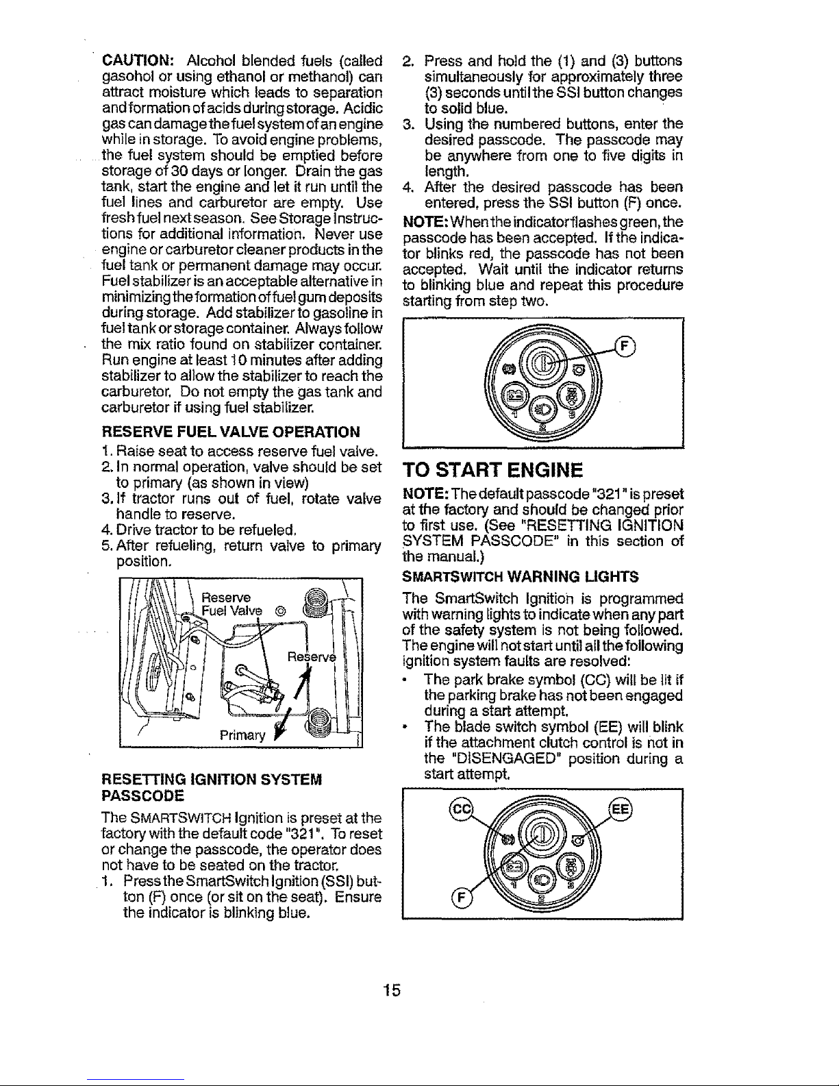
RESERVE FUEL VALVE OPERATION
1,Raise seat to access reserve fuel valve.
2. In normal operation, valve should be set
to primary (as shown in view)
3, If tractor runs out of fuel, rotate valve
handle to reserve.
4. Drive tractor to be refueled,
5.After refueling, return valve to primary
position.
Reserve
Fuel Valve @
Primary
RESETTING IGNITION SYSTEM
PASSCODE
The SMARTSWITCHIgnition ispreset at the
factory with the default code "321". To reset
or change the passcode, the operator does
not have to be seated on the tractor,
1. Pressthe SmartSwitch ignition (SSI)but-
ton (F)once (or sit on the seat). Ensure
the indicator is blinking blue.
2, Press and hold the (1) and (3) buttons
simultaneously for approximately three
(3)seconds untilthe SSI button changes
to solid blue.
3. Using the numbered buttons, enter the
desired passcode. The passcode may
be anywhere from one to five digits in
length.
4. After the desired passcode has been
entered, press the SSI button (F) once.
NOTE: Whenthe indicatorflashes green, the
passcode has been accepted. If the indica-
tor blinks red, the passcede has not been
accepted. Wait until the indicator returns
to blinking blue and repeat this procedure
starting from step two.
TO START ENGINE
NOTE: The default passcode "321" ispreset
at the factory and should be changed prior
to first use. (See "RESETTING IGNITION
SYSTEM PASSCODE" in this section of
the manual.)
SMARTSWITCHWARNING LIGHTS
The SmartSwitch Ignition is programmed
with warning lights to indicate when any part
of the safety system is not being followed.
The engine will notstart until all the following
ignition system faults are resolved:
• The park brake symbol (CC) will be lit if
the parking brakehas not been engaged
during a start attempt.
• The blade switch symbol (EE) will blink
if the attachment clutch control is not in
the "DISENGAGED" position during a
start attempt.
15
Page 16
$
PRE-START
• Ensure freewheel control is in the trans-
mission engaged position,
• Ensure transmission is in the neutral
position.
Move attachment clutch control to the
"DISENGAGED" position.
Siton seat inoperating position, depress
brake pedal and set parking brake,
SMARTSWITCHIGNITION UNLOCK
1, Press the SmartSwitch Ignition (SSI) but-
ton (F) once (or sit on the seat). Ensure
the indicator is blinking blue.
2. Enter passcode and press the SSI but-
ton. If passcode is not accepted, the
SSI button wifl blink red. Wait until the
SSI button returns to blinking btuebefore
attempting to re-enter passcode. Once
accepted, the SSi buttonwill flash green.
3, Ensure that the SmartSwitch Safety
System warning lights are not showing
any faults present. Ifany warning lights
do indicatefaults present, resolve those
faults before continuing withSTARTtNG.
STARTING :
The Briggs & Stratton Endurance engine
equipped with yourtractor features a Ready-
Start automatic choke system to provide
simplified starting in normal conditions.
Please read the following starting instruc-
tion carefully.
NOTE: For the first time starting after your
tractor has satfor anextended period oftime,
or after running out of gas, the engine may
require an extended start attempt to reprime
thefuel system. Foran extended start, press
andhold SSI button for three seconds before
releasing. This will promptthe engine to at-
tempt starting for upto ten seconds (instead
ofthe normal five seconds), allowing time for
fuel to be pulled into the engine.
NORMAL STARTING (32°F/0°Cand above)
1. Move throttle control to fast position
(,_).
2, Perform procedures outlined in "Smart-
Switch IGNITION UNLOCK" as previ-
ously described.
3. WhiletheSSt button (F)isflashinggreen,
press and release the SSI button once
more to start the engine.
o Once enginestarts, theattachments
and ground drive can now be used.
If the engine does not accept the
load, restart the engine and allow it
to warm up for one minute.
• Leave throttle control in fast position
(,_) while mowing.
COLD WEATHER STARTING (32°F/0°C
and below)
t. Move throttle control beyond fast posi-
tion (-t/_) into the cold weather starting
position (@).
2, Perform procedures outlined in "Smart-
Switch IGNITION UNLOCK" as previ-
ously described.
3. While the SSI button is flashing green,
press the SSt button once more to start
the engine,
• Once enginestarts, movethethrottte
control back to the fast position
(._) towarm-up. Thetime required
for warm-up will vary from a few
secondsto a minute depending upon
conditions and temperature.
• Leave throttle control infast position
(._) while mowing.
NOTE: Failure to move throttle from cold
weather starting position (@) will result in
poor engine performance and spark plug
fouling.
AUTOMATIC TRANSMISSION WARM UP
• Before driving the unit in cold weather,
the transmission should be warmed up
asfollows:
• Ensurethe tractor ison levelground.
. Release the parking brake and let
the brake slowly return to operating
position.
• Allow one minute fortransmission to
warm up. This can be done during
the engine warm up period.
• The attachments can atso be used dur-
ing the engine warm-up period after the
transmission has been warmed up.
PURGE TRANSMISSION
_CAUTION: Never engage or disengage
freewheel lever while the engine is running.
Toensureproper operation andperformance,
it is recommended that the transmission be
purged before operating tractor for the first
time,This procedure will removeanytrapped
air inside the transmission which may have
developed during shipping of your tractor.
IMPORTANT: Should your transmission
require removal for service or replacement,
itshould bepurged after reinstallation before
operating thetractor.
16
Page 17
1. Place tractor safely on a level surface -
that is clear of objects and open - with
engine off and parking brake set.
2. Disengage transmission by placing
freewheel control in disengaged position
(See "TO TRANSPORT" in this section
of manual).
3. Sitting in the tractor seat, start engine.
After the engine is running, move throttle
control to slow position. With motion
control lever in neutral position, slowly
disengage ciutchJbrake pedal.
,I_CAUTION: At any time, during step 4,
there maybe movement of the drive wheels.
4. Move motion control lever tofull forward
position and hold for five (5) seconds.
Move lever to full reverse position and
hold for five (5) seconds. Repeat this
procedure three (3) times,
5. Move motion controlleverto neutral posi-
tion.Shutoff engine andset parkingbrake.
6. Engage transmission by placing free-
wheel control in engaged position (See
"TO TRANSPORT" in this section of
manual),
7. Sitting in the tractor seat, start engine.
After the engine is running, move throttle
control to half (1/2) speed. With motion
control lever in neutral position, slowly
disengage clutch/brake pedal.
8. Slowly movemotioncontrol leverforward,
after the tractor moves approximately
five (5)feet (t ,5 m), slowly move motion
control lever to reverse position. After
the tractor moves approximately five (5)
feet (1,5 m) return the motion control
lever to the neutral position. Repeat this
procedure with the motion control lever
three (3)times,
Your transmission is now purged and now
ready for normal operation.
SERVICE MINDER!HOUR METER
Service minder shows the total number of
hours the engine hasrun andindicates when
the engine or mower needs servicing. After
every 50 hours of operation the oil can icon
will stay on for 2 hours. To service engine
and mower, see the Maintenance section
of this manual.
NOTE: The service minder runswhen either
the engine is running or the SmartSwitch is
active (unlocked).
MOWING TIPS
• DO NOT usetire chains when the mower
housing is attached to tractor.
• Mower should be properly leveledfor best
mowing performance. See "TO LEVEL
MOWER HOUSING" in the Service and
Adjustments sectionof this manual.
• The left hand side of mower should be
used for trimming.
• Drivesothat clippings are discharged onto
the area that hasalready been cut. Have
the cut area tothe right of the tractor. This
will result in a more even distribution of
clippings and more uniform cutting.
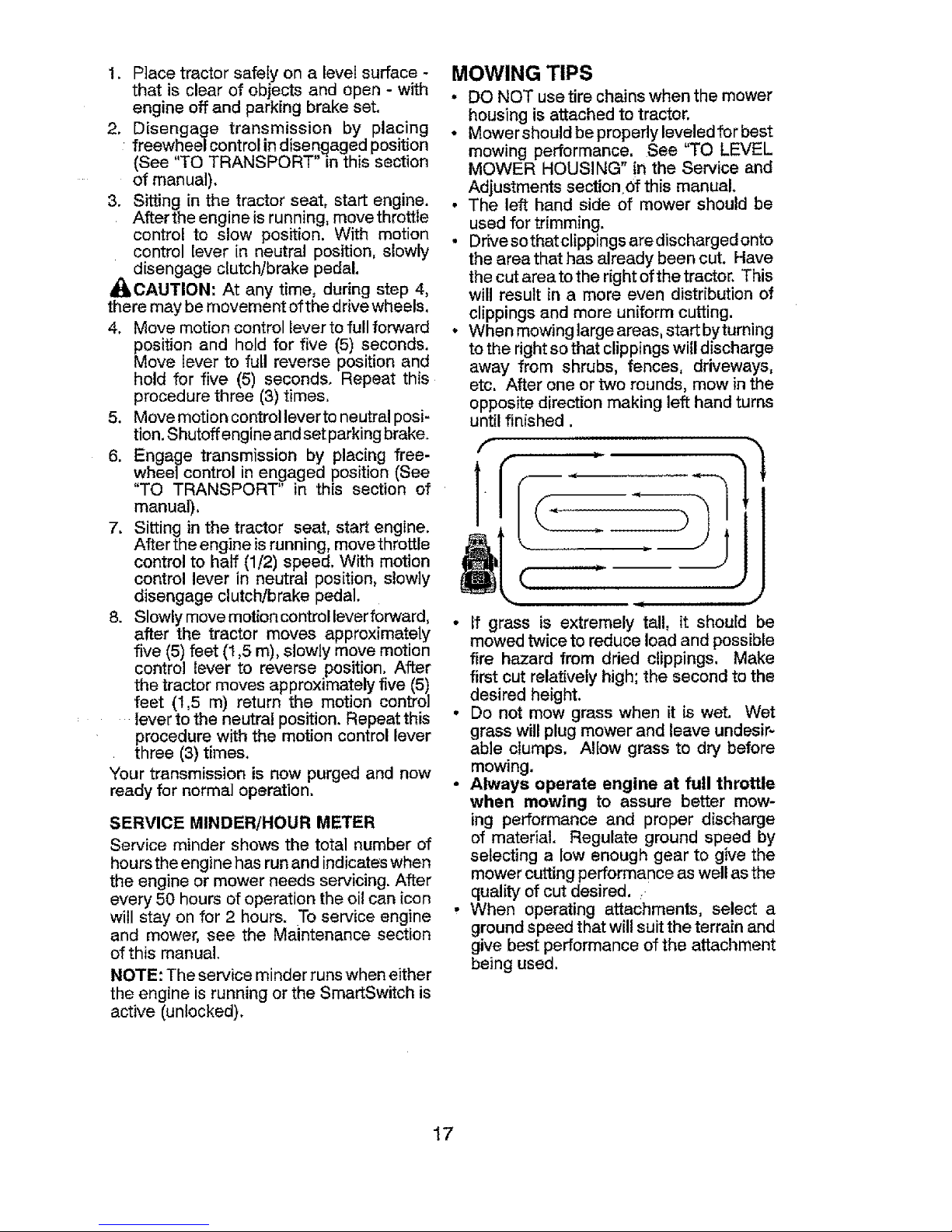
• When mowing large areas,start byturning
to the right sothat clippings will discharge
away from shrubs, fences, driveways,
etc. After one or two rounds, mow inthe
opposite direction making left hand turns
until finished.
f
(.
(
• If grass is extremely tall, it should be
mowed twice to reduce load and possible
fire hazard from dried clippings. Make
first cut relatively high; the second to the
desired height.
• Do not mow grass when it is wet, Wet
grass willplug mower and leave undesir-
able clumps. Allow grass to dry before
mowing.
• Always operate engine at full throttle
when mowing to assure better mow-
ing performance and proper discharge
of material. Regulate ground speed by
selecting a low enough gear to give the
mower cutting performance as well as the
quality of cut desired.
• When operating attachments, select a
ground speed that will suitthe terrain and
give best performance of the attachment
being used.
17
Page 18
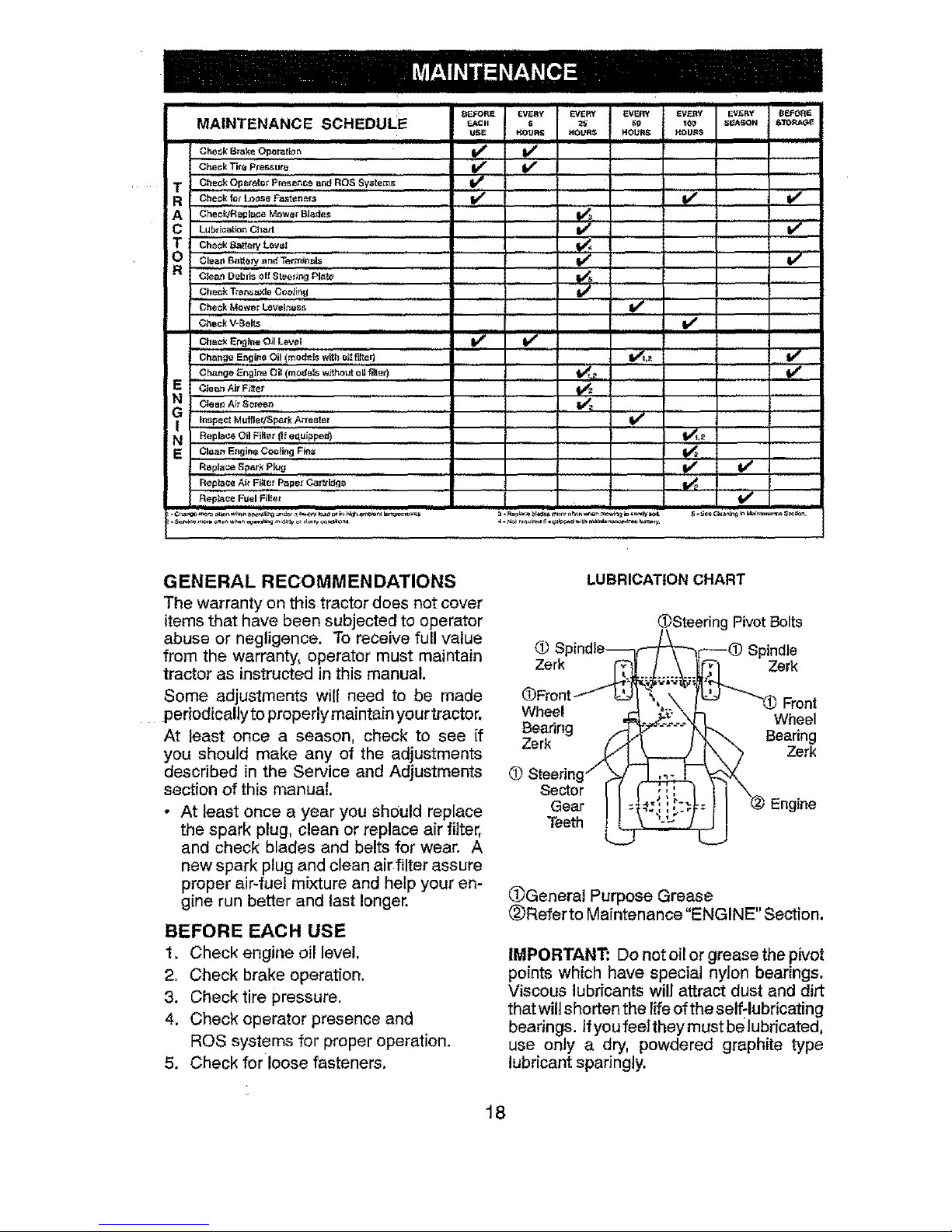
SCNEOULE o =o. o,..Y %. .,., ..... o .o
MAINTENANCE _c. _ re _o_ s_soN sTo_4,_
USE HOURS tlOURS HOURS HOU_S
' ,,,,,,,,,,,,,,,,,,,,,, ii
,,,,,,,,,,,,,,,,,,,,, i
Cheek Brake Oper,_lio n If V _
Che_ k Tits Pless ure .......i If , V"
T Ch=o'k'bpn_ato_ Prese_nce =nd"ROS SyStems V f,,,, '...........
R Cheok_o_ Lo_l_eFaste_ .... If V'
A ,,,,,,ChecP4R_pl=ce MOWer Blade_ ..... _ ......
.................................................. =
T Oheck 8artery Level _ I
O Clean Bakery a nd Terminals ........... ................
Cie_ Debds off Steedag Plate ....... _,,
Check T_'e_ e_Ie Ceot!r_g.................. tf
Check Mower Leveirtess V j ,,
........c_=okv-Bo,_, .......v"
Cheek Engine O;I L_VeI I_ If
Change Er_glne Oil (mods_s without eli filter) _,_ V e
E ¢|een Air Fitter
Oleni1,Air ........
Scle_
inspec_ Muffler/Spark Al'i-est et V _
N_ Replace Oil Filter (It e_.uippe_ _,_ ......
E Glean Engine CooEng Fins ..... V_=
Replac_ Spar_ Plug _
Replaca A{; Figer P_per ¢ar_idge
Rep_ce Fuel Fillet !1##
GENERAL RECOMMENDATIONS
The warrantyon thistractordoes notcover
itemsthat have been subjectedto operator
abuse or negligence. Toreceivefull value
fromthe warranty, operatormust maintain
tractor as instructedin this manual.
Some adjustments wil{ need to be made
periodicallyto properlymaintain yourtractor,
At least once a season, check to see if
you should make any of the adjustments
described in the Service and Adjustments
section of this manual,
- At least once a year you should replace
the spark plug, clean or replace air filter,
and check blades and belts for wear. A
new spark plug and clean air filter assure
proper air4uel mixture and help your en-
gine run better and last longer.
BEFORE EACH USE
1. Check engine oil level.
2. Check brake operation.
3. Check tire pressure.
4, Check operator presence and
ROS systems for proper operation.
5. Check for loose fasteners.
LUBRICATION CHART
(l_Steering Pivot Bolts
1_ Spindle_t,_--_r_---(_) Spindle
Zerk _._.;_ Zerk
(DFront---" _-41 k, _., fl_.tg- "_Front
Wheel 4_. _.'_ .":-,_I _VVheel
_eanng
. ,'_ ...... N _'_. Bear,ng
z.er_ _"\:_ - Zerk
(_ Steering / _/ _ 'y_-':/,,.
S_eC__ ',i_-t= }t \@ Engine
@_)Generat Purpose Grease ,
Relerto Maintenance ENGINE' Section.
IMPORTANT: Do not oil or grease the pivot
points which have special nylon bearings.
Viscous lubricants willattract dust and dirt
thatwilt shorten the lifeof the self:lubricating
bearings, tfyou feelthey must be lubricated,
use only a dry, powdered graphite type
lubricant sparingly.
18
Page 19
TRACTOR
Always observe safety ruIes when perform-
ing any maintenance,
BRAKE OPERATION
if tractor requires more than 5 feet (1,5 m)
to stop at highest speed in highest gear on
a level, dry concrete or paved surface, then
brake must be serviced, (See "TO CHECK
BRAKE" in the Service and Adjustments
section of this manual).
TIRES
- Maintain proper air pressure in all tires
(See the side of tires for proper PSI.)
- Keep tires free of gasoline, oil, or insect
control chemicals which can harm rubber.
• Avoid stumps, stones, deep ruts, sharp
objects andother hazards that may cause
tire damage,
NOTE: To seal tire punctures and prevent
flat tires due to slow leaks, tire sealant may
be purchased from your local parts dealer.
Tire sealant also prevents tire dry rot and
corrosion.
OPERATOR PRESENCE SYSTEM
AND REVERSE OPERATION SYSTEM
(ROS)
Ensure operator presence and reverse
operation systems are working properly. If
your tractor does notfunction as described,
repair the problem immediately.
• The engine should not start unless the
parking brake is engaged, and the attach-
ment clutch control is in the disengaged
position.
CHECK OPERATOR PRESENCE SYSTEM
• While the engine is running, any attempt
bythe operator to leave the seat without
first setting the parking brake should shut
off the engine,
• With the engine running, the parking
brakeengaged, andthe attachment clutch
engaged, any attempt by the operator to
leave the seat should shut off the attach-
ment clutch,
. The attachment clutch should never oper-
ate unless the operator is in the seat.
CHECK REVERSE OPERATION (ROS)
SYSTEM
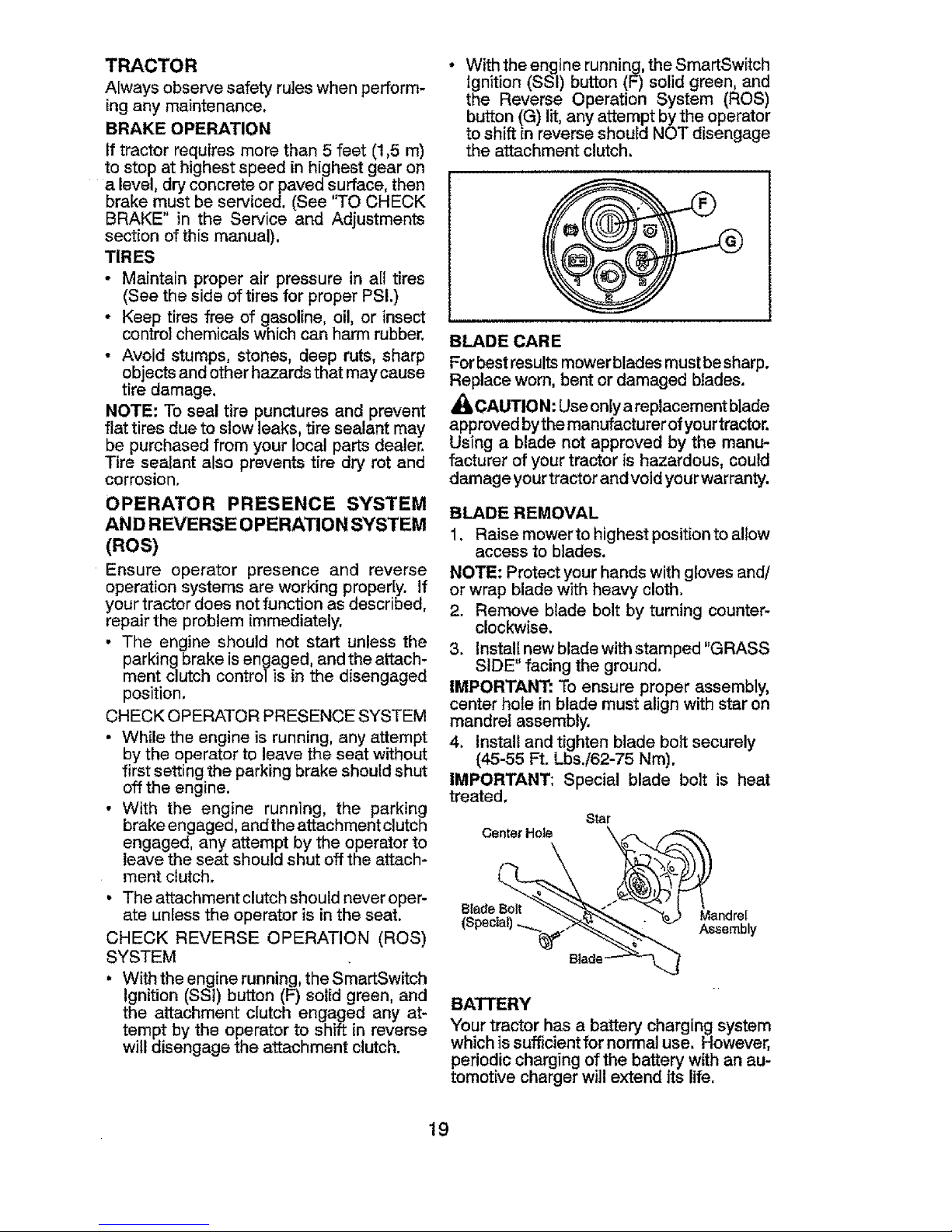
• With theengine running, the SmartSwitch
Ignition (SSi) button (F) solid green, and
the attachment clutch engaged any at-
tempt by the operator to shift in reverse
will disengage the attachment clutch.
- With the enginerunning, the SmartSwitch
Ignition (SSI) button (F) solid green, and
the Reverse Operation System (ROS)
button (G) lit, any attempt by the operator
to shift in reverse should NOT disengage
the attachment clutch.
BLADE CARE
For bestresultsmower bladesmust besharp.
Replace worn, bent or damaged blades.
_I=CAUTION: Use onlya replacement blade
approved bythe manufacturer ofyourtractor.
Using a blade not approved by the manu-
facturer of your tractor is hazardous, could
damage yourtractor and void your warranty.
BLADE REMOVAL
1. Raise mowerto highest position to allow
access to blades,
NOTE: Protect your hands with gloves and/
or wrap blade with heavy cloth.
2. Remove blade bolt by turning counter-
clockwise.
3. Instalt newblade with stamped "GRASS
SIDE" facing the ground.
IMPORTANT: To ensure proper assembly,
center hole in blade must align with star on
mandrel assembly,
4. Install and tighten blade bolt securely
(45-55 Ft. LbsJ62-75 Nm).
IMPORTANT: Special blade bolt is heat
treated.
Star
center Hole \i__
BATTERY
Your tractor has a battery charging system
whichis sufficientfor normaluse, However,
periodicchargingof the battery withan au-
tomotivechargerwill extendits life.
19
Page 20
• Keep batten/and terminals clean.
. Keep battery bolts tight.
• Keep small vent holes open.
• Recharge at 6-10 amperes for ! hour.
NOTE: The original equipment battery on
your tractor is maintenance free. Do not
attempt to open or remove caps or covers.
Adding or checking level of electrolyte is
not necessary.
TO CLEAN BATTERY AN DTERMt NALS
Corrosionanddirtonthe batte_and terminals
can cause the battery to "leak' power.
1. Remove terminal guard.
2. Disconnect BLACK battery cable first
then RED battery cable and remove
battery from tractor.
3. Rinse the battery with plain water and
dry.
4. Clean terminals and battery"cable ends
with wire brush until bright.
5. Coat terminals with grease or petroleum
jelly.
6. Reinstall battery (See "REPLACING
BATTERY" in the Service and Adjust-
ments section of this manual).
TRANSAXLE MAINTENANCE
The transmission fan and coolingfinsshould
be kept clean to assure proper cooling. Do
not attempt toclean fan ortransmission while
engine is running or while the transmission
ishot. Toprevent possible damage to seals.
do not use high pressure water or steam to
clean transaxle.
• Inspect cooling fan to be sure fan blades
are intact and clean.
• Inspectcoolingfinsfordirt, grass clippings
andother materials. To preventdamage to
seals, do not use compressed air or high
pressure sprayer to clean co'01ingfins.
TRANSAXLE PUMP FLUID
The transaxle was sealed atthe factory and
fluid maintenance is not required for the life
ofthe transaxle. Should the transaxle ever
leak or require servicing, contact your near-
est Sears or other qualified service center.
V-BELTS
CheckV-belts for deterioration andwear after
t O0hours of operation andreplace if neces-
sary. The belts are not adjustable. Replace
belts if they begin to slip from wear.
ENGINE
LUBRICATION
Onlyuse high quality detergent oil rated with
APIservice classification SG-SL. Selectthe
oil's SAE viscosity grade according to your
expected operating temperature,
NOTE: Although multi-viscosityoils (5W30,
10W30etc.) improvestarting incold weather,
they will result inincreased oi!consumption
when used above 32°F/0°C. Check your
engine oil level more frequently to avoid
possible engine damage from running low
onoil.
Change the oil after every 50 hours of
operation oratleast once ayearif thetractor
is not used for 50 hours in one year.
Checkthe crankcase oil level beforestarting
the engine and after each eight (8) hours
of operation. Tighten oil fill cap/dipstick
securely each time you check the oil level.
TO CHANGE ENGINE OIL
Determine temperature range expected
before oil change. All oil must meet API
service classification SG-SL.
, "Ensure tractor is on level surface.
• Oil will drain more freely when warm.
• Catch oil in a suitable container.
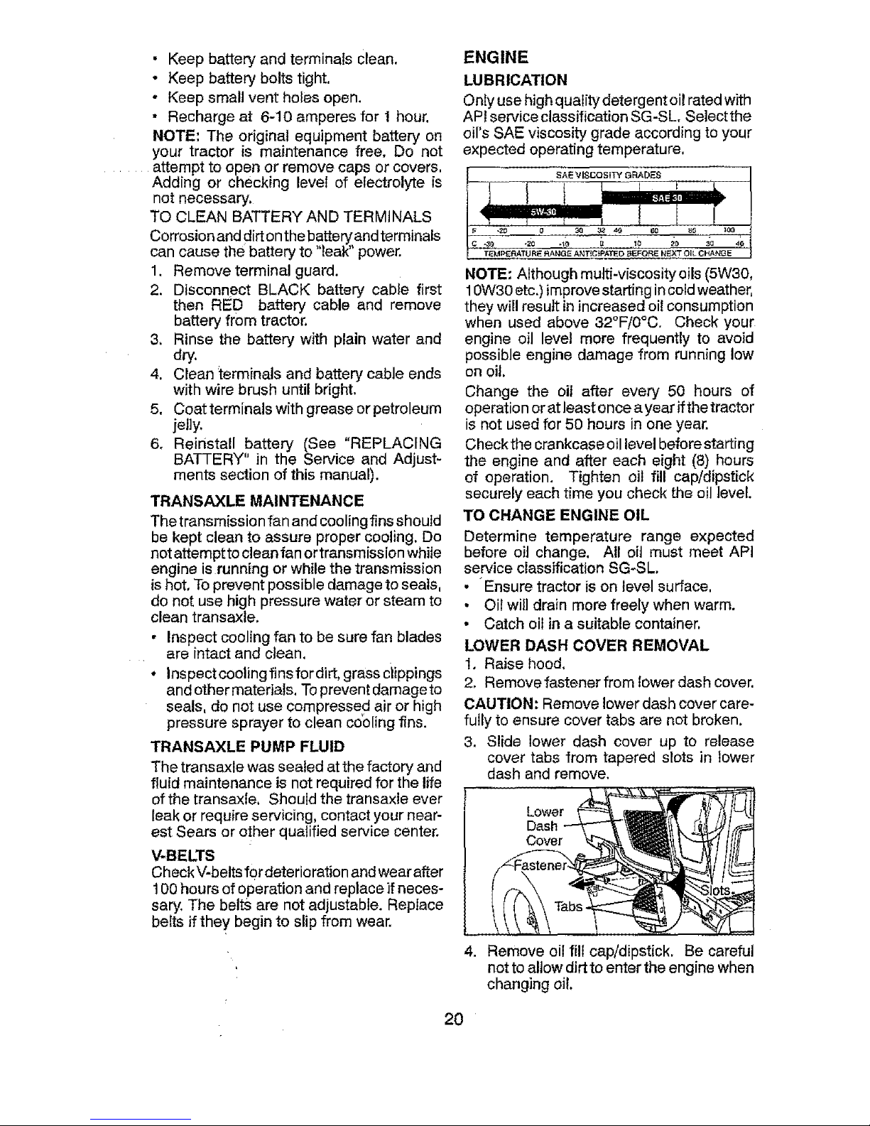
LOWER DASH COVER REMOVAL
1. Raise hood,
2. Remove fastener from lower dash cover.
CAUTION" Remove lower dash cover care-
fully to ensure cover tabs are not broken.
3. Slide lower dash cover up to release
cover tabs from tapered slots in lower
dash and remove.
Lower
Dash
4. Remove oil fill cap/dipstick. Be careful
not to allow dirtto enter the engine when
changing oil.
20
Page 21
5. Remove yellow cap from end of drain
valve and install the drain tube onto the
fitting.
6. Unlock drain valve by pushing inward
and turning counterclockwise.
7. To open, pull out onthe drain valve.
OilDrainValve
Ye,ow
8. After oilhasdrained completely, closeand
lock the drain valve by pushing inward
and turning clockwise until the pin is in
the locked position as shown.
9. Removethedraintubeand replacethecap
ontotothe bottomfitting ofthe drainvalve.
10.Refillenginewith oilthrough oilfill dipstick
tube. Pour slowly. Do not overfill. For
approximate capacity see "PRODUCT
SPECIFICATIONS"sectionofthismanual,
11.Usegauge onoilfillcap/dipstick for check-
ing level. Ensuredipstick cap istightened
securely for accurate reading. Keepoil at
"FULL' lineon dipstick. Tighten cap onto
the tube securely when finished.
ENGINE OIL FILTER
Replacetheengine oilfilter everyseason or
every other oil change ifthe tractor is used
more than 100 hours inone year.
NOTE: Ifneeded, removelowerdashcovers
usingsteps from"Lowerdashcoverremoval"
section ofthis manual.
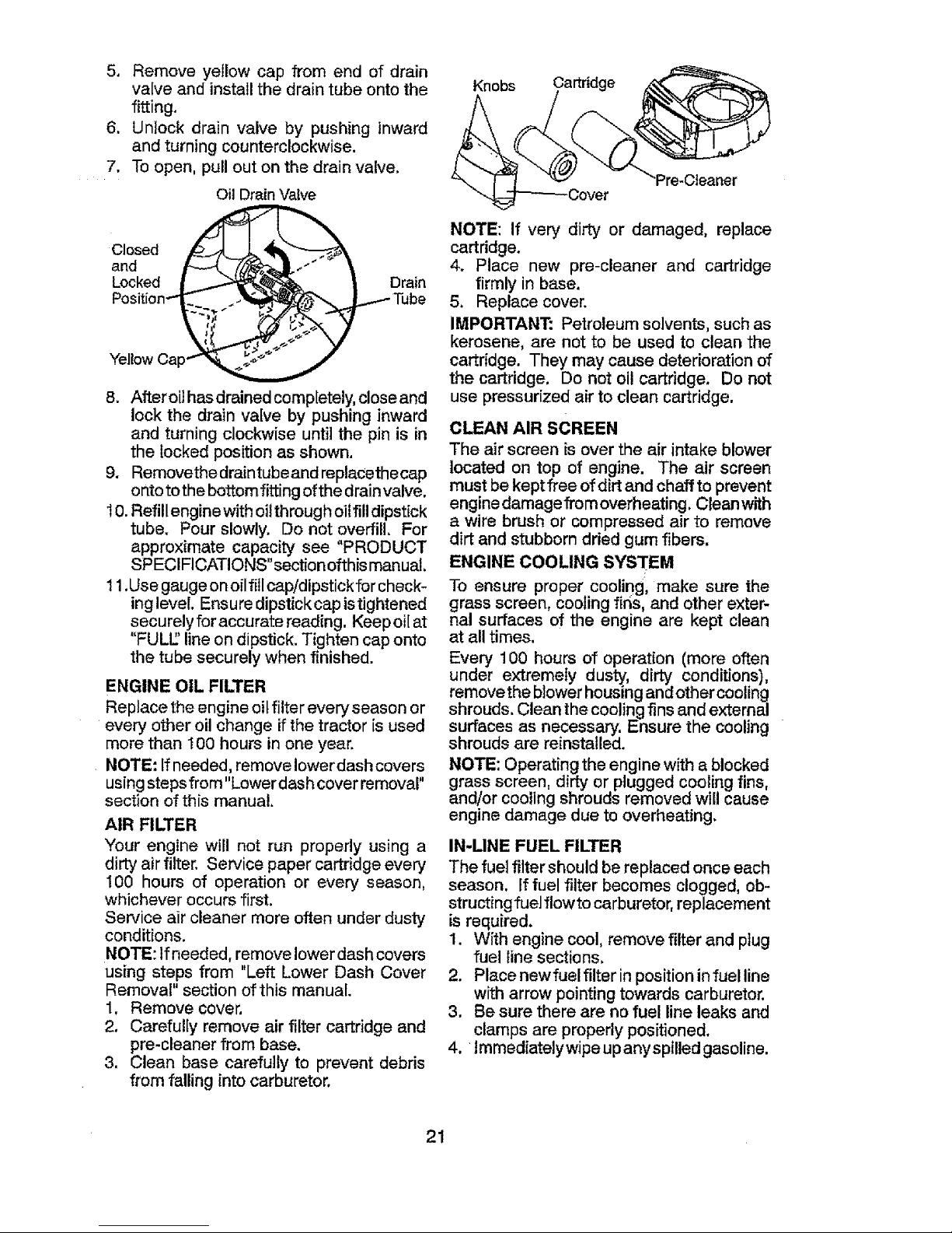
AIR FILTER
Your engine will not run properly using a
dirtyairfilter. Service paper cartridgeevery
100 hours of operation or every season,
whichever occursfirst.
Service air cleaner more oftenunder dusty
conditions.
NOTE: Ifneeded, removelowerdashcovers
using steps from "Left Lower Dash Cover
Removal" section of this manual.
1. Remove cover,
2. Carefully remove air filter cartridge and
pre-cleaner from base.
3. Clean base carefully to prevent debris
from falling into carburetor.
Knobs Cartridge
"Pre-Cteaner
NOTE: If very dirty or damaged, replace
cartridge.
4. Place new pre-cleaner and cartridge
firmly in base,
5. Replace cover.
IMPORTANT: Petroleum solvents, such as
kerosene, are not to be used to clean the
cartridge. They may cause deterioration of
the cartridge. Do not oil cartridge. Do not
use pressurized air to clean cartridge.
CLEAN AIR SCREEN
The air screen is over the air intake blower
located on top of engine. The air screen
mustbe keptfree ofdirt and chaffto prevent
engine damagefrom overheating.Cleanwith
a wire brushor compressed air to remove
dirtand stubborndried gum fibers.
ENGINE COOLING SYSTEM
To ensure proper cooling, make sure the
grass screen, cooling fir_s,and other exter-
nal surfaces of the engine are kept clean
at all times.
Every 100 hours of operation (more often
under extremely dusty, dirty conditions),
removethe blower housing and other cooling
shrouds. Clean thecooling fins and external
surfaces as necessary. Ensure the cooling
shrouds are reinstalled.
NOTE: Operating the engine with ablocked
grass screen, dirty or plugged cooling fins,
and/or cooling shrouds removed will cause
engine damage due to overheating.
IN-UNE FUEL FILTER
The fuelfiltershould be replaced once each
season. If fuelfilter becomes clogged, ob-
structing fuel flowtocarburetor,replacement
is required.
1. With engine cool, remove filter and plug
fuel line sections.
2. Place newfuel filter inposition infuel line
with arrow pointing towards carburetor.
3. Be sure there are no fuel line leaks and
clamps are properly positioned.
4. lmmediatelywipeupanyspilled gasoline.
21
Page 22
Clamp
Fuel Filter__"---_g
MUFFLER
Inspect and replace corroded muffler and
spark arrestor (ifequipped) as itcould create
afire hazard and/or damage.
SPARK PLUG(S)
Replacespark plug(s)atthe beginning ofeach
mowing season or after every I00 hours of
operation, whicheveroccurs first. Spark plug
type andgap settingareshownin"PRODUCT
SPECIFICATIONS" section of this manual,
CLEANING
• Clean engine, battery, seat, finish, etc.
of all foreign matter.
• Clean debris from steering plate. Debris
canrestrictclutch/brake peda!shaftmove-
ment, causing belt slipand loss of drive.
_&CAUTION: Avoid all pinch points and
movable parts
&____CIutch!brake ped_ey
tl c[_a. /' °,,y/f_ /.
Steer____j--
Steering System, Dash, Fender
andMowerNotShown
• Keep finished surfaces and wheels free
of all gasoline, oil, etc.
. Protect paintedsurfaces withautomotive
type wax,
Except for the washout port (if equipped),
we do not recommend using a garden hose
or pressure washer to clean the outside of
yourtractor unless the engine and transmis-
sion are covered to keep water out, Water
in engine or transmission will shorten the
useful life of your tractor. Use compressed
air or a leafblower to remove grass, leaves
and trash from outside tractor and mower.
DECK WASHOUT PORT
Your tractor's deck is equipped with a
washout port on its surface as part of its
deck wash system, tt should be utilized af-
ter each use,
1. Drive the tractor to a level, clear spot
on your lawn, near enough to a water
spigot for your garden hose to reach,
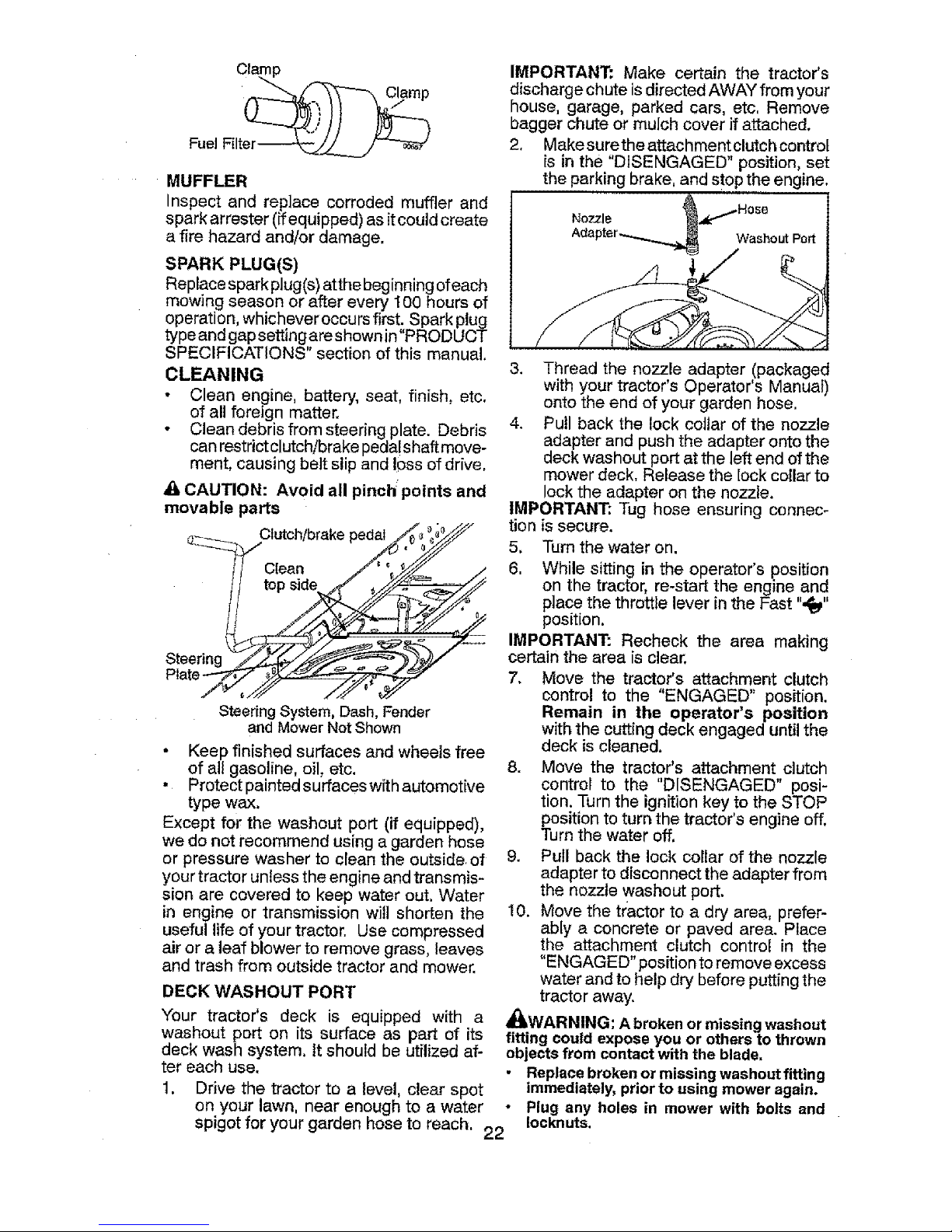
IMPORTANT: Make certain the tractor's
discharge chute isdirected AWAYfrom your
house, garage, parked cars, etc, Remove
bagger chute or mulch cover if attached,
2, Makesurethe attachment clutch controt
is in the "DISENGAGED" position, set
the parking brake, and stop the engine,
Nozzle ]
Washout Port
3. Thread the nozzle adapter (packaged
with your tractor's Operator's Manual)
onto the end of your garden hose,
4, Pull back the lock collar of the nozzle
adapter and push the adapter onto the
deck washout port at the left end of the
mower deck, Release the lock collar to
lock the adapter on the nozzle.
IMPORTANT.* Tug hose ensuring connec-
tion is secure.
5, Turn the water on.
6, While sitting in the operator's position
on the tractor, re-start the engine and
place the throttle lever in the Fast ",_"
position.
IMPORTANT: Recheck the area making
certain the area is clear.
7. Move the tractor's attachment clutch
control to the "ENGAGED" position.
Remain in the operator's position
with the cutting deck engaged until the
deck is cleaned.
8. Move the tractor's attachment clutch
control to the "DISENGAGED" posi-
tion, Turn the ignition key to the STOP
position to turn the tractor's engine off,
Turn the water off.
9. Pull back the lock collar of the nozzle
adapter to disconnect the adapter from
the nozzle washout port.
10. Move the tractor to a dry area, prefer-
ably a concrete or paved area. Place
the attachment clutch control in the
"ENGAGED" position to remove excess
water and to help dry before putting the
tractor away.
_WARNING: A broken or missing washout
fitting could expose you or others to thrown
objects from contact with the blade,
Replace broken or missing washout fitting
immediately, prior to using mower again.
• Plug any holes in mower with bolts and
Iocknuts.
22
Page 23
WARNING: TO AVOID SERIOUS INJURY, BEFORE PERFORMING ANY SERVICE OR
ADJUSTMENTS:
3.
4,
5.
6.
in contactwith plug,
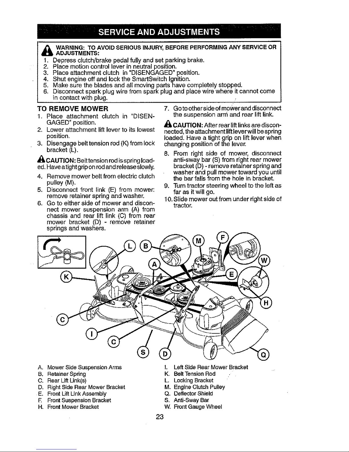
TO REMOVE MOWER
1. Place attachment clutch in "DISEN-
GAGED" position.
2, Lower attachment lift lever to itslowest
position.
3. Disengage belt tension rod (K)from lock
bracket (L),
_,CAUTION: Belttension rod isspring load-
ed.Have atightgrip onrodand releaseslowly.
4. Remove mower belt from electric clutch
5.
6.
Depress clutch/brake pedal fully and set parkingbrake.
Place motion control lever in neutral position.
Place attachment clutch in "DISENGAGED" position,
Shut engine offand lock the SmartSwitch Ignition.
Make sure the blades and all moving partshave completely stopped.
Disconnect spark plugwire from spark plug and placewire where it cannot come
pulley(M).
Disconnect front link (E) from mower:
remove retainer spring and washer.
Go to either side of mower and discon-
nect mower suspension arm (A) from
chassis and rear lift link (C) from rear
mower bracket (D) - remove retainer
springs and washers,
0!
7. Gotoother sideofm0wer anddisconnect
the suspension arm and rear lift link.
CAUTION: After rear lift linksarediscon-
nected, the attachment liftleverwill bespring
loaded. Have a tight grip on lift lever when
changing position of the lever.
8. From right side of mower, disconnect
anti-sway bar (S) from right rear mower
bracket (D)- remove retainer spring and
washer and pull mower toward you until
the bar falls from the hole in bracket.
9, Turn tractor steering wheel to the left as
far as it will go.
10,Slide mower out from under right side of
tractor.
A. Mower Side Suspension Arms
B. Retainer Spring
C. Rear Lift Link(s)
D. Right Side Rear Mower Bracket
E, Front Lift Link Assembly
E Front Suspension Bracket
H. Front Mower Bracket
I, Left Side Rear Mower Bracket
K, Belt Tension Rod
L, Locking Bracket
M, Engine Clutch Pulley
Q. Deflector Shield
S. Anti-Sway Bar
W. Front Gauge Wheel
23
Page 24

TO INSTALL MOWER
1. SET PARKING BRAKE LEVER AND
LOWER ATTACHMENT LiFT LEVER
• Depress clutch/brake pedal all the way
down and hold.
• Pull parking brake lever up and hold,
release pressure from clutch/brake
pedal, then release parking brake lever.
Pedal should remain in brake position.
Ensure parking brake will hold tractor
secure.
_CAUTION: Lift lever is spring loaded.
Have a tight grip on lift lever, lower it slowly
and engage in lowest position. Lift lever is
located on left side of fender.
Lift
Lever
2. ASSEMBLE FRONT GAUGE WHEEL
(W) TO FRONT OF MOWER
H. Front Mower Bracket
W. Front Gauge Wheel
X. Shoulder Bo]t
Y, 1-1/40.D. Washer
Z. 3/8-16 Locknut
3. TURN STEERING WHEEL LEFT AND
POSITION MOWER
° Turn steering wheel to the left as far as it
will go andposition mower onrightside of
tractorwith deflectorshield (Q)tothe right.
Front
fEngine
'_ Transaxle
Q. Deflector Shield
4. SLIDE MOWER UNDER TRACTOR
° Bring belt forward and check be[tfor pro-
per routing in all mower pulley grooves,
NOTE: Ensure mower side suspension arms
(A) are pointing forward before sliding mower
under tractor,
• Slide mower under tractor until it is
centered under tractor.
j
A. Mower Side Su_ }ension Arms
Q. Deflector Shield
24
Page 25

5, INSTALL ANTI-SWAY BAR (S)
(IF EQUIPPED)
ANTI-SWAY BAR (S)
.,_ Towards Towards
Transaxle MowerDeck_'_
90" End integrated Washer End
• From right side of mower, first insert
90° end of anti-sway bar (S) into hole in
transaxIe bracket (_, located near left
rear tire infront of transaxfe.
NOTE: Flashlight may be helpful.
TransaxleBracket(T)
LocatedBetweenRearTires
NOTE: Depending on model, bracket(T) may
be different than shown but hole for anti-sway
bar will be in same position/location,
• Pivot the integrated washer end of anti-
sway bar (S) towards mower deckbracket
on right side of mower. Insert integrated
washer end of bar into hole inrear mower
bracket (D), Move mower as needed to
insert integrated washer end of bar into
rear mower bracket (D).
• Secure with small washer and small
retainer spring as shown.
D. RightSideRear MowerBracket
S. Anti-SwayBar
"11.TransaxJeBracket
l 1
6. ATTACH MOWER SIDE SUSPENSION
ARMS (A) TO CHASSIS
, Positionfront hole inside suspension arm
(A)over pin on outside oftractor chassis
and secure with large washer and large
retainer spring (B),
Repeat on opposite side of tractor.
A, MowerSideSuspensionArms
B. RetainerSpring
D. RightSideRearMowerBracket
7. ATTACH REAR LIFT LINKS (C)
• Insert rod end of rear lift link (C) into hole
(U) in tractor lift shaft suspension arm
and pivot link down to mower.
• Lift rear corner of mower and position slot
in link assembly over pin on rear mower
bracket (D)andsecurewith largewasher
and large retainer spring.
- Repeat on opposite side of tractor.
25
Page 26

C. Rear Lift Link(s)
D. Right Side Rear Mower Bracket
'U. Hole
8 ATTACH FRONT LINK (E)
• "SJrn steering wheel to position wheels
straight forward.
• From front of tractor, insert rod end of
front link (E) through front hole in tractor
front suspension bracket (F).
• Move to left side of rnower and and insert
large retainer spring (G) through hole in
front link (E) behind front suspension
bracket (F).
- Insert other end of link (E) into hole in
front mower bracket (H) and secure with
washer and small retainer spring (J),
NOTE: Requires deck lifting.
/ Y'\_ '
Front Link / _ _;[:::_-E_9
Location. i _, ......" _ , ........
9 INSTALL BELT ON ENGINE CLUTCH
PULLEY (M)
• Disengage belt tension rod (K) from
locking bracket (L).
• Install belt onto engine clutch pulley (M).
M,Engine
Clutch Pulley
IMPORTANT: Check belt for proper muting
in all mower pulley grooves and under
mandrel covers.
• Engage belt tension rod (K) on locking
bracket (L).
_h,CAUTION: Belt tension rod is spring
loaded. Have atight grip on rod and engage
slowly.
Raise attachment lift lever to highest
position.
• If necessary, adjust gauge wheels
before operating mower asshown in the
Operation section of this manual.
MOWER DRIVE BELT INSTALLATION
Follow procedure described in "TO
REPLACE MOWER BLADE DRIVE BELT"
inthis section of this manual.
5. FrontLiftLink Assernbly
E Front Suspension Bracket
G. Large Retainer Spring
H. Front Mower Bracket
J. Small Retainer Spring
M. Engine Clutch Pulley
26
Page 27

TO LEVEL MOWER
Ensure tires are properly inflatedto the PSi
shown on tires. If tires are over or under
inflated, it may affect the appearance ofyour
lawn and lead you to think the mower is not
adjusted properly.
VISUAL SIDE-TO-SIDE ADJUSTMENT
1. With alltires properly inflated and ifyour
lawn appears unevenly cut, determine
which side of mower is cutting lower.
NOTE: As desired, you can raise the low
side of mower or lower the high side.
2. Go to side of mower you wish to adjust.
3. With a 3/4" or adjustable wrench, turn
lift link adjustment nut (A) to the left to
lower the mower, or,to the right to raise
the mower.
5. Recheck measurements; adjust ifneces-
saryuntil both sides are equal.
FRONT-TO-BACK ADJUSTMENT
IMPORTANT: Deck must be level side-
to-side.
To obtainthe best cutting results, the mower
blades should be adjusted so the front tip
is 1/8 to 1/2" (3,1 to 12,7 mm) (lower than
the rear tip when the mower is in itshighest
position.
_I=CAUTION: Blades are sharp. Protect
your hands with gloves and!or wrap blade
with heavy cloth.
• Raise mower to highest position.
• Position any blade so the tip is pointing
straight forward. Measure distance "B" to
the ground at front and rear tip of blade.
Turn nut Turn nut
right to left to
raise tower
mower mower
NOTE: Each full turn of adjustment nut will
change mower height about3/16" (4,7 mm).
4. Test your adjustment by mowing some
uncut grass and visually checking the
appearance. Readjust, ifnecessary, until
you are satisfied with the results.
PRECISION SIDE-TO-SIDE ADJUSTMENT
1. With alltires properly inflated, parktractor
on [evef ground or driveway,
_CAUTION: Blades are sharp. Protect
your hands with gloves and!or wrap blade
with heavy cloth.
2. Raise mower to its highest position.
3. At both sides of mower, position blade
at side and measure distance "A" from
bottom edge of bladeto ground. The dis-
tance should bethe same on both sides,
4. If adjustment is necessary, see steps in
Visual Adjustment instructions above,
........... 1a
• If front tipof blade isnot 1/8 to 1/2" (3,1
to 12,7 ram) lower than the reartip, go to
the front oftractor.
• With an 11/16" or adjustable wrench,
loosen jam nut "A" several turns to clear
adjustment nut "B".
• With a 3/4" or adjustable wrench, turn
frontlink adjustment nut"B" clockwise (f_)
(tighten) to raise the front of mower, or,
counterclockwise (_'_)(loosen) to lower
the front mower.
Tighten adjust Loosen adjust
nut"B" to nut "B" to
raise mower lowermower
Loosen jam nut "A" first
NOTE: Each full turn of adjustment nut will
changemower height about1/8" (3,1 mm).
• Recheck measurements, adjust if neces-
sary until front tip of blade is 1/8 to 1/2"
(3,1 to 12,7 mm) lower than the rear tip.
• Hold adjustment nut in position with
wrench and tighten jam nut securely
against adjustment nut.
27
Page 28

TO REPLACE MOWER BLADE DRIVE
BELT
MOWER DRIVE BELT REMOVAL
1. Park tractor on a level surface, Engage
parking brake.
2, Lower attachment lift lever to its lowest
.... position,
3. Disengage belttension rod (K)from lock
bracket (L),
CAUTION: Belt tension rod is spring
loaded. Have afirm grip on rod and release
slowly.
4. Remove screws (P) from R,H. and L.H,
mandrel covers and remove covers (Q).
5. Remove any dirtorgrass clippingswhich
may have accumulated around mandrels
and entire upper deck surface.
6, Remove belt from electric clutch pulley
(M), both mandrel pulleys (R)and allidler
pulleys (V).
MOWER DRIVE BELT INSTALLATION
1, Install belt around both mandrel pulleys
(R)and around id[erpulleys (V)asshown.
2. Install belt onto electric clutch pulley (M).
IMPORTANT: Check belt for proper routing
in all mower pulley grooves.
3, Reassemble R,H. and L.H. mandrel cov-
ers (Q). Securely tighten all screws.
4. Engage belt tension rod (K) on locking
bracket (L).
_, CAUTION: Belt tension rod is spring
loaded. Have atight grip on rod and engage
slowly.
5, Raise attachment lift lever to highest
position.
%
J
28
Page 29

TO REPLACE MOTION DRIVE BELT
Park the tractor on level surface. Engage
parking brake. For assistance, there is a
belt installation guide decal on bottom side
of left footrest.
BELT REMOVAL -
1. Remove mower (See "TO REMOVE
MOWER" in this section of manual).
NOTE: Observe entire motion drive belt
and positionof all belt guides and keepers.
2. Disconnect clutch wire harness (A).
3. Remove anti-rotation link (B) on right
side of tractor.
4. Remove belt from stationary idler ((3)
and clutching idler (D).
5. Remove belt from centerspan idler (E).
6. Pull belt slack toward rear of tractor.
Carefully remove belt upwards from
transmission inputpulley and over cool-
ing fan blades (F).
7. Remove belt downward from engine
pulley and around electric clutch (G).
8. Slide belt toward rear of tractor, off the
steeringplate (H)andremovefromtractor.
BELT INSTALLATION -
1. Install new belt from tractor rearto front,
over the steering plate (H) and above
clutch brake pedal shaft (J).
2. Pull belttowardfrontoftractorand rollbelt
around electric clutch and onto engine
putley (G).
3. Pull belt toward rear of tractor. Carefully
work belt down around transmission
cooling fan and ontothe input pulley (F).
.... Be sure belt is inside the belt keeper.
4. Install belt on centerspan idler (E).
5. install belt through stationary idler (C)
and clutching idler (D).
6. Reinstall anti-rotation link (B) on right
side of tractor. Tighten securely.
7. Reconnect clutch harness (A).
8. Make sure belt is in all pulley grooves
and inside all belt guides and keepers.
9. Install mower (See "TO INSTALL MOW-
ER" in this section of manual).
TO CHECK BRAKE
iftractor requires more than five (5)feet (1,5
m) to stop at highest speed in highest gear
on a level, dry concrete or paved surface,
then brake must be serviced.
You mayalso check brake by:
1. Park tractor on a level, dry concrete or
paved surface, depress brake pedal all
the way down and engage parking brake.
2. Disengage transmission by placing
freewheel control in '_ransmission dis-
engaged" position. Pullfreewheel control
out and into the slot and release so it is
held inthe disengaged position.
The rear wheels must lock and skid when
you try tomanually push thetractor forward.
If the rear wheels rotate, then the brake
needs to be serviced. Contact a Sears or
other qualified service center.
TO REMOVE WHEEL FOR REPAIRS
1. Block up axle securely.
2. Remove axle cover, retaining ring and
washers to allow wheel removal (rear
wheelshave a square key- Do notlose).
3. Repairtireand reassemble.
29
Page 30

NOTE: On rearwheels only: align grooves in
rear wheel hub and axle. lnsert square key.
4. Replace washers and snap retaining ring
securely in axle groove.
5, Replace axle cover.
NOTE: To seal tire punctures and prevent
flat tires due to slow leaks, purchase and
usetire sealantfrom Sears. Tire sealant also
prevents tire dry rot and corrosion.
Washers
Retaining
Axle
Cover
2.
3.
4.
5.
Ke_
(RearWheelOnly)
FRONT WHEEL TOE-IN/CAMBER
Your new tractor front wheel toe-in and
camber is set at the factory and is normal.
The front wheel toe-in and camber are not
adjustable. If damage has occurred to
affect the factory set front wheel toe-in or
camber, contact a Sears or other qualified
service center.
TRANSAXLE MOTION CONTROL LE-
VER NEUTRAL ADJUSTMENT
The motion control leverhas beenpreset
at the factory and adjustmentshould not
be necessary.
1. Loosenadjustmentbolt infront ofthe
right rear wheel, and lightly tighten.
Start engine and move motion con-
trol lever until tractor does not move
forward or bacl<ward.
Hold motion control lever in that posi-
tion and turn engine off.
While holding motion control ]ever in
place, loosen the adjustment bolt,
Move motion control lever to the neu-
tral (N) (lock gate) position,
6, Tighten adjustment bolt securely.
NOTE: If additional clearance is needed
to get to adjustment bolt, move mower
deck height to the lowest position.
After above adjustment is made, if the
tractor still Creepsforward or backward
while motion control lever is in neutral
position, follow these steps:
1. Loosen the adjustment bolt.
2. Move the motion control lever 1/4 to
1/2 inch in the direction it is trying to
creep.
3. Tighten adjustment bolt securely.
4. Start engine and test.
5. If tractor still creeps, repeat above
steps until satisfied.
Motion Control AdjustmentBolt
_ / ....._:..... i Lock Gate
TOSTART ENGINEWITH WEAK BATTERY
_WARNING: Lead-acid batteries gener-
ate explosive gases, Keep sparks, flame
andsmoking materials away from batteries.
Always wear eye protection when around
batteries,
tfyour battery istooweakto startthe engine,it
shouldbe recharged. (See"BATt'ERY" inthe
MAINTENANCE section of this manual).
If "jumper cables" are used for emergency
starting, follow this procedure:
IMPORTANT: Your tractor is equipped with
a12volt system. The other vehicle mustalso
be a 12volt system. Do not use your tractor
battery to start other vehicles.
TO ATTACH JUMPER CABLES -
1. Connect one end of the RED cableto the
POSITIVE (+)terminal ofeachbattery(A-
B), taking care notto short against tractor
chassis.
2. Connect one end of the BLACK cable
to the NEGATIVE (-)terminal (C) of fully
charged battery.
3. Connect the other end of the BLACK
cable (D) to good chassis ground, away
from fuel tank and battery.
TO REMOVECABLES, REVERSEORDER-
1. BLACK cablefirst from chassis andthen
from the fully charged battery.
2. RED cable last from both batteries.
Weak or
Dead
Battery
REPLACING BATTERY
_WARNING: Do not short battePy terminals
by allowing a wrench or any other object to
contact both terminals at the same time.
Before connecting battery, remove metal
bracelets, wristwatch bands, rings, etc.
Positive terminal must be connected first to
prevent sparking from accidental grounding,
1. Lift seat pan to raised position.
30
Page 31

2. Discon nect BLACK battery cablefirstthen
RED battery cable and carefully remove
battery from tractor,
3. Install new battery with terminals in same
position as old battery,
4, First connect RED battery cable to posi-
tive (+) terminal with hex bolt and keps
nut as shown. Tighten securely. Slide
terminal cover over terminal
5. Connect BLACK grounding cable to
negative (-) terminal with remaining hex
bolt and keps nut, Tighten securely
Terminal
Cover iNKut ps
"-(_, Hex
" Bolt
Positive
(Red)
Cable Negative(Black)
Cable
TO REPLACE HEADLIGHT BULB
1. Raise hood,
2. Remove bulb holder from the hole inthe
backside of the grill.
3. Replace bulb in holder and install bulb
holder securely back intothe hole inthe
backside of the grill,
4, Close hood.
INTERLOCKS AND RELAYS
Loose or damaged wiring may cause your
tractor to runpoorly, stop running, or prevent
it from starting.
* Check widng,
TO REPLACE FUSE
Replace with 20 amp automotive-type plug-
in fuse, The fuse holder is located behind
the dash.
SMARTSWITCHIGNITION SYSTEM
LIGHTS
The SmartSwitch System is equipped with
courtesy lights that are used to indicate
system functions or faults.
FUNCTIONS
• The SmartSwitch Ignition (SSI) Button
(F) will blink blue while waiting for the
correct passcode to be entered. The
SSI button will blink green when tractor
is ready to start and remain solid green
while running,
• The park brake symbol (CC) will be lit ff
the parking brake hasnot been engaged
during a start attempt,
- The blade switch symbol will blink if the
attachment clutch control is not in the
"DISENGAGED" position during a start
attempt.
• The Reverse Operation System (ROS)
button (G) will be lit when Reverse Op-
eration System is in use,
• The Headlight button (H) will remain lit
while headlights are in use.
• During normal operation, the Battery
Indicator button (I)will not be lit.
FAULTS
• The SSI Button will blink red for two
seconds ifthe wrong passcode has been
entered.
• The Reverse Operation System (ROS)
button will blink when there is a fault
with the Reverse Operation System.
See "Reverse Operation System" in the
Operation section of this manual,
• Afterthe first unsuccessfutstart attempt,
the battery indicator button (I) will blink
fortwo (2)seconds andthen stay lit.This
indicates thatthe batteryvoltage isbelow
normal operating level. While engine is
in operation, this light may also indicate
a charging system failure.
• The headlight button will blink when one
or both of the headlight bulbs fail.
- All indicator lights will blink in the event
the engine shuts offfor unknown reasons;
for example, if the engine has run out of
fuel.
31
Page 32

TO REMOVE HOOD &GRILLASSEMBLY
1. Raise hood.
2. Unsnap headlight wire connector.
3, Remove retainer clip and washer from
right hand pivot pin.
4. Stand in front of tractor. Grasp hood at
sides and slide left removing hood from
pivot pins and lifthood off of tractor.
5. When replacing hood, reconnect the
headlight wire connector, and reinstall
the washer and retainer clip on the
right hand pivot pin.
Left Pivot Pin
Washer
Retainer
Right Pivot
Pin
Headlight Wire
Connector
TRANSMISSION REMOVAL/
REPLACEMENT
Should yourtransmissio'n requireremovalfor
service or replacement, itshould be purged
after reinstaliation and before operating the
tractor, See"PURGE TRANSMISSION" in
the Operation section of this manual.
ENGINE
TO ADJUST THROTTLE CONTROL
CABLE
The throttle control has been preset at
the factory and adjustment should not be
necessary Check adjustment as described
below before loosening cable. If adjustment
is necessary, Seeengine manual.
32
Page 33

Immediately prepareyourtractorfor storage
atthe end of the season or ifthe tractor will
not be used for 30 days or more.
,_WARNING: Never store thetractorwith
gasoline inthe tank inside a building where
fumes may reach an open flame or spark.
Allow the engine to cool before storing in
any enclosure.
TRACTOR
Remove mower from tractor for winterstor-
age. When mower isto bestored foraperiod
of time, clean it thoroughly, remove all dirt,
grease, leaves, etc. Store inaclean, dryarea,
1, Clean entiretractor (See"CLEANING" in
the Maintenance section ofthis manual).
2. Inspect and replace belts, if necessary
(See belt replacement instructions inthe
Service and Adjustments section of this
manual).
3. Lubricate as shown in the Maintenance
section of this manual.
4. Ensure that all nuts, bolts and screws
are securely fastened, inspect moving
parts for damage, breakage and wear.
Replace if necessary.
5. Touch up all rusted or chipped paint
surfaces; sand lightly before painting.
BATTERY
• Fully charge the battery for storage.
• After a period of time in storage, battery
may require recharging.
• To help prevent corrosion and power
leakage during long periods of storage,
battery cables should be disconnected
and battery cleaned thoroughly (see "TO
CLEAN BATTERY AND TERMINALS" in
the Maintenance section of this manual),
- After cleaning, leave cablesdisconnected
and placecables where they cannot come
in contact with battery terminals.
• If battery is removed from tractor for
storage, do not store battery directlyon
concrete or damp surfaces.
• If unit is equipped with battery indicator/
charging plug, an optional charging unit
may be purchased and connected to the
unitto charge the battery duringlongterm
storage. Inspect and clean the battery
terminals as needed prior to long term
storage with charger connected.
ENGINE
FUEL SYSTEM
IMPORTANT: It is important to prevent
gum deposits from forming inessential fuel
system parts such as carburetor, fuel hose,
ortankduring storage. Also, alcohol blended
fuels (called gasohol or using ethanol or
methanol) can attract moisture which leads
to separation and formation of acids during
storage. Acidic gas can damage the fuel
system of an engine while in storage.
• Empty thefuel tank byStartingthe engine
and letting it run until the fuel lines and
carburetor are empty.
• Never use engine or carburetor cleaner
products in the fuel tank or permanent
damage may occur.
Use fresh fuel next season,
NOTE: Fuel stabilizer is an acceptable al-
ternative in minimizing the formation of fuel
gum deposits during storage. Add stabilizer
to gasoline in fuel tank or storage container.
Always foUowthemix ratio found on stabilizer
container. Run engine at least 10 minutes
afteradding stabilizer to aUowthestabilizer to
reach the carburetor. Do not empty the gas
tank and carburetor if using fuel stabilizer,
ENGINE OIL
Drain oil (with engine warm) and replace
with clean engine oil. (See "ENGINE" inthe
Maintenance section of this manual).
CYLINDER(S)
1. Remove spark plug(s).
2. Pour one ounce (29.5 mL) of oil through
spark plug hole(s) into cylinder(s).
3. Distribute oil by setting parking brake,
disengaging attachmentclutch and using
the SmartSwitch Ignition (SSI)to attempt
a start, The oil will be distributed during
the approximate 5 second start*up at-
tempt.
4. Replace with new spark plug(s).
OTHER
- Do notstore gasoline from one season to
another.
• Replaceyour gasolinecan ifyour canstarts
to rust. Rust and/or dirt in your gasoline
will cause problems.
• If possible, store your tractor indoors and
coveritto giveprotection from dust anddirt.
- Cover your tractor with asuitable protec*
rive cover that does not retain moisture.
Do notuseplastic. Plastic cannot breathe
which allowscondensation toform andwill
cause your tractor to rust.
IMPORTANT: Never cover tractor while
engine and exhaust areas are still warm,
33
Page 34

TROUBLESHOOTING CHART:
See appropriate section in manual unless directed to Sears service center
PROBLEM CAUSE CORRECTION
Will not start
Hard to start
Engine will not
turn over
Engine clicks but
will not start
1
2
3
4
5
6
7
8
1
2
3
4
5
6
7
1
2
3
4
5
6
7
8
9
1
2
3
4
............. , , ,,, , ,
Out of fuel. 1 Fill fuel tank.
Engine flooded, 2 Wait several minutes before
attempting to start.
Bad spark piug. 3 Replace spark plug,
Dirty air filter, 4 ! Clean/replace air filter. ,
Dirty fuel filter, 5 i Replace fuel filter.
Water in fuel. 6 =.Empty fuel tank and carburetor,
refill tank with fresh gasoline and
replace fuel filter.
Loose or damaged wiring, 7 Check all wiring.
Engine valves out of adjustment. 8 : Contact a qualified service center
. , ,,,
Dirty air filter, 1 Clean/replace air filter.
Bad spark p)ug, 2 : Replace spark plug,
Weak or dead battery, 3 Recharge or replace battery.
Dirty,fuel filter, 4 Replace fuel filter,
Stale or dirty fuel, 5 Empty fuel tank and refill tank
with fresh, clean gasoline.
Loose or damaged wiring. 6 Check all wiring.
Engine valves out of adjustment, 7 Contact a qualified service center.
Clutch/brake pedal not depressed, 1 Depress clutch/brake pedal,
Attachment clutch is engaged. 2 Disengage attachment clutch.
Weak or dead battery. 3 Recharge or replace battery.
Blown fuse. 4 Replace fuse.
Corroded battery terminals, 5 Clean battery terminals.
Loose or damaged widng. 6 Check all widng.
Fauity ignition switch. 7 Check/replace ignition switch.
Faulty solenoid or starter, 8 Check/replace solenoid or starter.
Faulty operator presence 9 Contact a qualified service center.
switch(as),
Weak or dead battery, 1 Recharge or replace battery.
Corroded battery terminals, 2 Clean battery terminals,
Loose or damaged wiring. 3 Check all wiring.
Faulty solenoid or sta_ar, 4 Check!replace solenoid or starter.
34
Page 35

TROUBLESHOOTING CHART:
See appropriate section in manual unless directed to Sears service center
PROBLEM
Loss of power
CAUSE CORRECTION
,, ,,,,,u,,,,,,,,, , ,
Cutting too much grass/too fast. 1 Raise cutting height!reduce
speed.
2 Throttle in cold weather starting 2 Move throttle control to fast
position (_)). position ('11_)-
3 Build-up of grass, leaves and 3 Clean underside of mower
trash under mower.
4 Dirty air filter.
5 Low oil level/dirty oit,
6 Faulty spark plug.
7 Dirty fuel filter.
J8 Stale or dirty fuel.
9 Water in fuel.
10 Spark plug wire loose.
i 1 Dirty engine air screen/fins.
t2 Dirty/clogged muffler.
housing.
4 Clean/replace air filter.
5 Check oil level/change oil.
6 Clean and regap or change spark
plug.
7 Replace fuel filter.
8 Empty fuel tank and refill tank witf"
fresh, clean gasoline.
9 Empty fuel tank and carburetor,
refill tank with fresh gasoline and
replace fuel filter,
10 Connect/Tighten spark plug wire.
11 Clean engine air screenflins.
12 Clean/replace muffler.
.... , ,,,,,
Engine continues to
run when operator
leaves seat with
attachment clutch
engaged
,, ,,, ,,,
Poor cut _ uneven
cutting
13 Loose or damaged wiring. 13
14 Engine valves out of adjustment. 14
,,,,,,,,,,,,L
1 Worn, bent or loose blade. 1
2 Bent blade mandrel. 2
3 Loose/damaged part(s). 3
;i Faultyoperai'or-safety presence .........1
control system.
1 Worn, bent or loose blade,
2 Mower deck not level,
3 Buildup of grass, leaves, and
trash under mower.
4 Bent blade mandrel,
5 Clogged mower deck vent from
build-up of grass, leaves, and
trash around mandrels.
1
2
3
4_
5
Check all wiring.
contact.....aq_iifiedservicece,n!er.
Replace blade, Tighten blade bolt
Contact a qualified service center.
Tighten loose part(s).
Replace damaged parts.
Check wiring, switches and
connections. If not corrected,
contact a qualified service center.
CAUTION: DO NOT
operate machine until
problem is corrected.
Replace blade.Tigbtenbiade b01t.
Level mower deck,
Clean underside of mower
housing,
Contact a qualified service center.
Clean around mandrels to
open vent holes,
35
Page 36

TROUBLESHOOTING CHART:
See appropriate section in manual unless directed to Sears service center
PROBLEM
Mower blades will 1
not rotate
2
3
4
Poor grass 1
discharge
2
3
4
5
6
7
8
9
10
11
Headlight(s) not 1
working
(if so equipped) 2
3
4
5
Battery will not 1
charge
2
3
4
CAUSE
Obetroctioninclutchmechanical'"1'
Worn/damaged mower drive belt 2
Frozen idler pulley. 3
Frozen blade mandrel, 4
Engine speed too slow. ! 1
Travel speed too fast. i 2
Wet grass. :3
Mower deck not level. ;4
Low!uneven tire air pressure. 5
Worn, bent or loose blade. 6
Buiidup of grass, leaves and 7
trash under mower.
Mower drive belt worn. 8
Blades improperly installed. 9
Improper blades used. 10
Clogged mower deck vent holes 11
from buildup of grass, leaves, and
trash around mandrels.
Light switch is "OFF". 1
Bulb(s) or lamp(s) burned out. 2
Faulty light sw!tch.
Loose or damaged wiring.
Blown fuse.
Bad battery cell(s).
Poor cable connections.
Faulty regulator (if so equipped).
Faulty alternator.
CORRECTION
Remove obstruction,
Replace mower drive belt.
Replace idler puBey.
Contact a qualified service center.
Place throttle control in "FAST"
position.
Shift to slower speed.
Allow grass to dry before mowing
Level mower deck.
Check tires for proper PSI.
Replace/sharpen blade. Tighten
blade bolt.
Clean underside of mower
housing.
I Replace mower drive belt.
i Reinstall blades sharp edge down
Replace with blades listed in
this manual.
Clean around mandrels to
open vent holes.
Turn light switch "ON".
Replace bulb(s) or tamp(s).
Check/replace SmartSwitch
Ignition switch.
4 Cl_eck wiring and connections.
5 Replace fuse.
1 Replace batte_.
2 Check/clean all connections.
3 Replace regulator.
4 Replace alternator,
36
Page 37

TROUBLESHOOTING CHART;
See appropriate section in manual unless directed to Sears service center
PROBLEM CAUSE CORRECTION
Loss of drive 1 Freewheel control in 1 Place freewheel control in
"DISENGAGED" position. "ENGAGED" position.
2 Debris on steering plate (if 2 See "CLEANING" in the
equipped), maintenance section.
3 Motion drive belt worn, damaged, 3 Reptace motion drive belt.
or broken,
4 Air trapped in transmission during 4 Purge transmission.
shipment or servicing,
5 Axle key missing, 5 Install axle keyat rear wheel. See
='TOREMOVE WHEEL" in the
Service and Adjustments section,
,, ,,,,,,,,,,,,,,,,,, ,,,,,,,,,,,,,,,,,,,,,,,,,,,,,,,,
Engine"backfires" 1 Engine throttle control not sel 1 Move throttlecontrolbetween
when turning between half and full speed (_stl half and full speed (fast) position
engine "OFF" position before stopping engine, before stopping engine.
Engine dies when 1 Reveme operation system (ROS) 1 Turn ignition key to ROS "ON"
tractor is shifted is not "ON" while mower or other position. See Operation section.
into reverse attachment is engaged.
.oRE.,
Youtl find the answer and more on managemyhome.com - for free!
, Find this and all your other product manuals ontine. _:
• Get answers from our team of home experts.
• Get a personatized maintenance plan for your home. _i
• Find information and tools to he[p with home projects. _i
manage home ii
_ ....... bIeu_ht to youby Se_,rs _ _!i
37
Page 38

SUGGESTED GUIDE FOR SIGHTING SLOPES FOR SAFE OPERATION
Co
ONLY RIDE UP AND DOWN HILL,
NOT ACROSS HILL
15 DEGREES MAX.
WARNING: To avoid serious injury, operate your tractor up and
down the face of slopes, never across the face. Do not mow
slopes greater than 15 degrees. Make turns gradually to prevent
tipping or loss of control. Exercise extreme caution when
changing direction on slopes,
1. Fold this page along dotted line indicated above.
2. Hold page before you so that its left edge is vertically parallef to a tree
trunk or other upright structure.
3. Sight across the fold in the direction of hill slope you want to measure.
4. Compare the angle of the fold with the slope of the hiil.
Page 39

Garant[a .......................................................... 39
Reglas de Seguridad ...................................... 40
Especificaciones del Producto ........................ 43
Monta|e!Pre Operaci6n ................................... 44
Operaci6n ....................................................... 46
.... Mantenimiento ................................................ 55
Prograrna de Manten[miento .......................... 55
Servicio y Ajustes ........................................... 60
Atmacenamiento ............................................. 70
Ident[ficaciSn de Problemas ........................... 71
Servicio Sears ............................. Contraportada
GARANTiA LIMITADA DE CRAFTSMAN
DURANTEDOSANOS a partir de Ia fecha de compra, todas las piezas no fung[bles de este equipo est_n
gamntizaotas centre defectos en losmateriales ota mane de obra. Con elcompmbante de tempts, una p[eza no
fungible con defectos se reparar_, o cambiar_ de forms gratuita a opci6n del vendedor.
Garantia limltada de la bateria
DURANTE 90 DiAS a partirde la fecha de compra, la baterfa (una pieza fungible) de este equipo est_ garantizada
centre defectos en los materiales o la mane de obra. Con el comprobante de compra, usted recibir&una bater[a
nueva, sin cargo. Usted es responsable del costs de la mane de obra deinstalaci6n de labater_a.
Otras garantfas limitadas
5n las siguientes garantlas adicionales, usted es responsable del coste de la mane de obra de instalaci6n de Ia
. pieza despu6s del segundo a=3ode la fecha de compra.
DURANTE CINCO ANOS a partir de la fecha de compraoel bastidor de este equipo est& garantizado contra
cualquier defecto en los materisles o Ia mane de obra. Con el cemprobante de compra, usted recibir& un nuevo
bastidor, sin cargo.
DURANTE DIEZ AI_OS a partir de la feoha de compra, el eje delantero de este equipo est,_ garantizade centre
cualquier defecto en los materiales o en la mane deobra. Con el comprobante de tempts, usted recibir& un nuevo
eje sin ningOn costoo
SIEMPRE QUE SEA USADO per el propietario original despu_s del d_cirno abe a paltir de la fecha de compra,
el hierro fundido deI eje delantero (si Io tiene) de este equipo est& garantizado contra cualquier defecto en los
materiales o la mane de obra. Con el compmbante de compra, usted recibir_ un nuevo bistro fundido deI eje
delantero de forrna gratuita.
SERVICIO DE GARANTiA
Pars obtener detalles de la cobertura de la garantfa sobre reparaoiones o sustitucionesgratuitas, visits Ia p&gina
web: wvcw,craftsman.comiwarranty
Sustitucibn del producto
si no se puede reparar o sustituirel pieza, usted recibir_, un nuevo equipo del mismo modelo o equivalents,
Restricci6n de garant_a
Esta garantia ser_ nula si este productose utilize aiguna vez pars brindar servicioscomerciales o si se alquila a
otra persona.
Esta garantia cubre !_INICAMENTE defectos de material y mane de obra, La cobertura de garant_a NO [ncluye;
• Oomponentes fungibles (excepto la baterta) que se puedan desgastar per el use normal dentro del perfodo de
garanti'a, inclose (pero sin limitarse a ello) hojas, bujfas, correas y filtrosde ace[te, airs y gasoline.
• Servicios de mantenimiento est,_.ndar'oambios de aceite o afinaciones.
• Reernplazo o reparaci6n de neum,_ticos per pinchazos causados per objetos extemos come clavos, espinas,
tocones o vid_os.
• Reemplazo o reparaci6n de neum&ticos o _edas per desgaste normal, accidentes o per operaci6n o
mantenimisnto incorrectos,
• Reparaciones necesarias per abuse del operador, incluso (pero sin Iirnitarse a ello) defies caasados per
remo[car obietos que superen la capacidad del equipo tractor, chocar centre objetos que doblen el bastidor' el
conjunto del eje o el eig,3eSal o sebrepasar ]a velooidad deI motor.
• Reparaciones necesadas per negligencia del operador' incluso (pete sin ]imitarse a silo) daSos e[_ctricos y
mec&nicos causados per el almacenamiento incorrecto, per no userel grade y la cantidad correctos de aceite de
motor, per no mantener del muelle Iibre de residues inflamables o per no mantener el equipo tractor de acuerdo
con tas instrucciones que contiene el manual del operador.
• Limpieza o reparaciones del motor (sistema de combustible) cuando se determine que se us6 combustible
contaminado y oxidado (sarro). En general, el combustibledebe usarse dentin de los 30 dias posteriores a su
compra.
• Deterioro y ctesgaste normal de los acabados extedores o sustituci6n de r6tulos de productos.
Esta garantia leotorga derechos legales especfficos, y ustsd tambi_n puede tener oti'os derachos que varian de
un estado a otto.
SearsBrandsManagementCorporation,HoffmanEstates,IL 60179_
39 "
Page 40

_lb PELIGRO: Esta Maquina cortadora es capaz de amputar las manosy los pies y de lanzar
objetos, si no se observan las instrucciones de seguridad siguientes se pueden producir
lesiones graves o la muerte.
....... _tL ADVERTENCIA: Siempre desconecteelalam_ *
bre de Ia bujia y p6ngalodonde no pueda entrar
en contacto con [a bujia, para evitar el arranque
por accidente, durante la preparaci6n, el trans- *
porte, el ajuste ocuando se hacen reparaciones.
_ ADVERTENCIA: Noavance cuestaabajo apun- *
to muerto yaque podriaperder el controlde1tractor. .
_ADVERTENOIA: Remolque solamente los
accesorios recemendados y conformes a Ias
caracteristicas indicadas pot el fabricante de su
tractor. Tenga cuidado y prudencia al utilizar el
tractor. Cuando se encuentre en un declive, oper
utilizando exclusivamente lavelocidad m&sbaja.
En caso de un dec[ive una carga excesiva po- •
dda resultar peligrosa. Losneum&ticos pueden
perder la tracci6n con el sue[o y hacerle perder °
e! control de su tractor.
ADVERTENOtA: Eltubo de escape del motor,
algunos de sus constituyentes y algunos com-
ponentes del vehiculo contienen o desprenden
productos qu[micos conocidos en el Estado de
California como causa de c&ncer y defectos al
nacimiento u otros daSos reproductivos,
,_ADVERTENCIA: Los bornes, terminales
y accesorios relativos de Ia bateria contienen
plomo o compuestos de plomo,productos quimi-
cos conocidos en el Estado de California como
causa de c&ncer y defectos al nacimiento u otros
daSosreproductivos. Lavar las manos despu_s
de manipularlos.
I. NINOS
_ADVERTENCIA: LOS NI_[OS PUEDEN
SUFRIR DANOS CON EL USO DEESTE EQUI-
PO. La Academia Estadounidense de Pediatria
(American Academy of Pediatrics) recomienda
que s61o se permita a nitros con una edad mini-
ma de 12 aSos manejar m&quinas cortacesped
manuales, y al menos de 16 argospara manejar
tractores cortac6sped.
ADVERTENCIA: LOS NI_"_]OSPUEDEN SU-
FRIR HERIDAS GRAVES O MUERTEA CAUSA
DEESTE EQUIPO. Leaysigaatentamente todas
Ias instrucciones siguientes
Si el operador no pone atenci6n a la presencia
de los niSos pueden ocurriraccidentes tr&gicos.
Los niSosa menudo est_.natraidos por la m&qui-
nay las actividad de cortar. No dar pot hecho
de que los niSos se queden adonde estaban la
51timavez que los vistes.
Mantener,los nifios fuera del ,_reade corte y ...........
vigilados por un adulto responsable aueno
sea el operador,
Estar alerta y apagar la m&quina si un nifios
entra en el &tea.
Antesy durante Iamarcha atr&s, mirar adelante
y abajo para ver si hay nifios pequefios.
Nunca Ilevar ni_os, inciuso si hay Ias cuchillas
apagadas. Podrian caer y herirse seriamente
ointerferircon el funcionamiento seguro de la
m&quina, los nifios que se han llevado prec-
edentemente puedenaparecer de pronto en el
&teade corte pototro paseo y set atropellados
otumbados por la m&quina.
Nunca dejar que los ni!_os manipulen la
m&quina,
Tener el m_ximo cuidado cuando se acerca
a cantos ciegos, arbustos, _,rboles u otros
objetos que pueden impedir la vista de nifios,
II. FUNCIONAMIENTO GENERAL
* Leer,entenderyseguirtodaslas instrucciones
sobre la m&quina yen el manual antes de
empezar.
. No poner las manos o lospiescerca de partes
giratorias o debajo de la m&quina. Mantener
siempre Iimpia laabertura de descarga.
, Permitirel funcionamientode lam&quina s61o
a adultos que tengan familiaridad con las
instrucciones.
. Limpiar et &rea de objetos como piedras,
juguetes, cables, etc. que pueden ser recogi-
dos y disparados con las cuchit[as.
. Asegurarse de que el &rea est_ tibre de otras
personas antes de ponerla en marcha. Parar
la m_.quina si afguien entra en el &rea,
. Nunca Ilevar pasajeros.
. No cortar marcha atr&s al no ser absotu-
tamente necesario. Mirar siempre abajo y
delante mientras se procede atr_s.
. Nunca dirigir el material descargado hacia ha-
die, Evitar descargar material contra paredes
u obstrucciones. El material podria rebotar
hacia el opetador. Parar [ascuchillas cuando
se pasan superficies de grava.
• No maneje la m&quina si no tiene Ia trarnpa
parac_sped completa, Ia canaletade descarga
u otros dispositivos de seguridad en su lugar
yen funcionamiento.
• Ralentizar antes de girar.
40
Page 41

• Nunca deje una m&quina en marcha sin
Supervisi6n. Detenga siempre las cuchillas,
active el freno de estacionamiento y detenga
el motor antes de abandonar la m&quina.
..............Bloquee rnnanuatrnente el interruptor de ar-
ranque. (Consulte "BLOQUEO MANUAL DEL
INTERRUPTOR DE ARRANQUE SMART-
SWITCH TM"en la secci6n de Funcionamiento
de este manual).
° Desenganche las hojas cuando no est@
cortando c_sped. Apague el motor y espere
basra que todas las partes se detengan por
cornpleto antes de limpiar la m&quina, retirar
la trarnpa para c@spedo destapar lacanaleta
de desoarga.
• Hacer funcionar la m_.quinas61ocon la luz deI
dia o luzartificial buena.
• No hacer funcionar Ia m&quina estando bajo
los efectos de alcohol o droga.
• Poner atenci6n al trY.rico cuando se opera
cerca de callas o se cruzan.
• Poner ta m_xima atenci6n al cargar o descar-
gar la m&quina en una caravanao camibn.
° Llevar siempre gafas de protecciOn cuando se
hace funcionar lam&quina.
° Use protectores de oidos para evitar dafios en
la audici6n.
• Los datos indican que los operadores a partir
de los 60 aSos est&n afectados por un gran
porcentaje de heridas relativas a la conducci6n
del cortac@sped. Estos operadores tendrian
que evaluar su habilidad de hacer funcionar
el cortac_sped de modo 1obastante seguro
para proteger a si misrnos y a otras personas
de heridas graves.
- Seguir las recomendaciones del fabricante
para los pesos y contrapesos de las ruedas.
• Mantener la m_quina libre de hierba, hojas
u otros escombros que pueden tocar el
tubo de escape / partes de] motor calientes
y quemarse. No permitir que el puente deI
cortac,_sped cargue hojas u otros residuos
que pueden causar acumulaciones. Limpiar
toda salpicadura de aceite o carburante antes
de hacer operaciones sobre la m_.quina o
guardar[a. Dejarla enfriar antes de guardarla.
IlL FUNCIONAMIENTO EN PENDIENTES
Las pendientes son el mayor factor de acoiden-
tes relativos a la p_rdida de control y vuelco,
que pueden causar severas heridas o muerte.
El funcionamiento en pendientes requiere una
atenci6n extra. Si no es posible hacer marcha
atr&s en una pendiente o site sientes incomodo,
no la cortes.
ADVERTENCIA: AI cargar o descargar la
rn_,quina, no sobrepase el &ngulo m_ximo reco-
mendado de 15°,
• Cortar hasia arriba y abajo de una pendiente,
no de rnodo horizontal.
-Poner atenciones a los hoyos, las ralces, los
bultos, las piedras u otros objetos escondidos.
..... El terreno irregular puede volcar la m_.quina.
La hierba alta puede esconder obstAculos.
- Escoger una velocidad de rnarcha baja de
rnodoque nosea necesario pararse o cambiar
estando en una pendiente.
• Nocortar la hierba rnojada. Las ruedas pueden
perder tracci6n. Poner siernpre una marcha
cuandose es_ en pendientes.
• No porter en punto rnuerto e ir cuesta abajo.
• Evitararrancar, pararse ogirar en una pendien-
te, Si las ruedas pierden tracci6n, desconectar
tas cuchillas y proceder despacio cuesta abajo
en la pendiente.
• Mantener todo los rnovimientos en las pen-
dientes lentos y gradual. No hacer cambios
repentinos de ve]ocidad o direcci6n, ya que
pueden causar el escape de la m&quina.
• Porter la m&xima atenci6n cuando Ia mbquina
funciona con captadores de hierba u otros
dispositivos enganchados; pueden afectar Ia
estabilidad de la mbquina. No usar en pendi-
entes empinados.
• No intentar estabilizar tambquina poniendo eI
pie en elterreno.
• No cortar cerca de bajadas, cunetas y odtlas.
Las m&quina puede volcarse improvisamente
si una rueda estb en el borde o se hunde.
• Si la m_,quina se para mientras va cuesta
arriba, desconectar las cuchillas, poner la
marcha atr&s y ir hacia atr_ts despacio.
• No girar estando en pendientes si no es nece-
sario, y luego girar despaqio y gradualrnente
cuesta abajo, si es posib!e.
IV, REMOLQUE
• Remolcars6]o conuna rn&quina que tenga un
ganchodise_ado pararernoJcar.Enganchar el
equipoo rernolcarsblo en el punto dispuesto
al efecto.
• Seguirlasrecomendaciones del productorcon
respectoa los l_mitesdel equipo por remolcar
y el rernolqueen pendientes.
. Nunca permitir que niSos u otras personas
est_n dentro delequipo porrernolcar.
• . En pendientes, el pesodel equipo rernolcado
puede causar la p@rdidade tracci6ny la p_r-
dida de control.
- Viajar despacio y dejar m&s distancia para
frenar.
41
Page 42

V. SERVICIO
MANIPULACION SEGURA DE LA GASOLINA
Para evitar heridas personales o dafios alas
............cosas, poner el m_Lximocuidado.a ]a hera de
manipular la gasolina, La gasolina es extrema-
mente inflamable y los vapores son explosives.
• Apagar todos los cigarrillos, cigarros, pipas y
otras fuentes de ignici6n,
• Usar s61ocontenederes para gasolina aproba-
dos.
• Nunca quitar el tap6n de la gasolina o afiadir
carburante con e! motor en marcha,
• dejar enfriar el motor antes del abastecimiento
de la gasotinao
• Nunca abastecer Ia m_.quinaal interior de un
local.
• Nunca guardar la m&quina o el contenedor
de{ carburante donde haya una Itamaabierta,
chispas o,una luz piloto come un calentador
de agua uotros dispositivos.
• Nunca I]enar los contenedores al interior de
un vehfculo o en una caravana o cami6n
recubiertos con un forro de pl&stico. Colocar
siempre los contenedores en el terreno lejos
deI vehfculo cuando se est& tlenando,
- Quitar el equipo degas del cami6n o caravana
y abastecerlo en et terreno. Si noes posible,
abastecer dicho equipo con uncontenedor por-
t_.til,m_s bien que de unsurtidor de gasolina,
• Mantener la boquilla a contacto del borde
deI dep6sito de carburante o la abertura deI
contenedor durante toda la operaciSn de
abastecimiento. No utilizar un dispositivo con
boquilta cerrada-abierta.
• Si se vierte carburante sobre Ia ropa, cambi-
arse ta ropainmediatamente.
• Nunca Ilenar el dep6sito rods de Io debido.
Volver a colecar el tap6n del gas y cerrar de
mode firme.
OPERACIONES DE SERVtCtO GENERALES
• Nunca hacerfuncionar Ia m&quina en un &tea
cerrada.
• Mantener todas tastuercas y pernos apretados
para asegurarse deque trabaja en condiciones
seguras.
• Nunca manipule los dispositivos de seguri-
dad. Nunca interfiera con la operaci6n de un
dispositivo de seguridad o reducir la protec-
ci6n proporcionada per un dispositivo de
seguddad, Verifique elfuncionarniento correcto
con regularidad. NUNCA utilice una m&quina
con un dispositivo de seguridad que no estd
funcionando correctamente
• Mantener la mdquina libre de hierba, hojas
u otros residues acumulados. Umpiar las
salpicaduras de aceite o carburante y quitar
cualquier cosa mojada con carburante. Dejar
que la m_.quina se enfrie antes de guardar]a,
• Si se golpea un objeto ajeno, hay que pararse
e inspeccionar [a m&quina. Reparar, si es
necesario, antes de volver a porter en marcha.
• Nunca hacer ning0n ajuste o reparaci6n con
el motor en funci6n.
• Verifique los componentes de la trampa para
c6sped y la canaleta dedescarga con frecuen-
ciay sustituya con repuestos reeomendados
per el fabricante cuando sea necesario.
• Las cuchillas del cortac@sped son afi[adas.
Envotver la cuchilla, ponerse guantes y poner
la m_ima atenci6n cuando se hacen opera-
clones en elias.
• Controlar el funcionamiento del freno/recuent-
emente. Ajustar y hacer Ias operaciones de
mantenimiento cuando eso sea necesario.
• Mantener ysustituir Iasetiquetas de seguridad
e instrucci6n, cuando sea necesario.
®
Use protectores de ofdos para evitar dafios en la
audici6n,
Llevar siempre galas de protecci6n cuando se hace
funcionar la m_.quina.
42
Page 43

ESPECIFICACIONES DEL PRODUCTO
Capacidad y Tipo
de Gasoline:
Tipo de Aceite
APt: SG-SL):
...... Capacidad de
Aceite:
Bujia
Sistema de
Carga:
Bateria:
Torsi6n del Perno
de la Cuchilla:
4.0 Galenes/15,14 L
Regular Sin Plomo *
SAE30 (eobre 32°F/0_0)
SAESW30 (deabajo 32°F/0°C)
Con Filtro: 64 0zj1o89 L
Sin Filtro: 60 Oz./1,77 L
Champion RC12YC
(Abertura: .030"/0,76 ram)
16 Amps @ 3600 RPM
AmpiHr: 28
Min. CCA; 230
Modelo TamaSo: UIR
45-55 Ft. Lbs./62-75 Nm
*_1_ Este m_,quinapuede utilizar gasoline con
_contenido de hastael 10%de etanel(El0). u_
usedeunagasolinaquesupereel 10%de etano]
(El0) anular&Iagarantfadel producto.
FELICITAOIONES per Iacompra desu tractor. Ha
sidedise_ado, planmcadoy fabdcado paredarle la
mejor cont_abilidad yel meier rendimiento posible.
En el case de que se encuentre con cualquier
problema que no pueda solucionar f&cilmente,
haga el favor de ponerse en contacto con un
centre de servicio Sears o con un otro centre de
servicio cualiflcado, Cuenta con representantes
bien capacitados y competentes y con Ias her-
ramientas adecuadas para darle servicio opara
reparar este tractor.
Haga el favor de leer y de guarder este manual.
Estas instruc-ciones le permitir&n reenter y man-
tener su unidad en forma adecuada. Siempre
observe las "REGLAS DE SEGURIDAD."
RESPONSABILIDADES DEL CLIENTE
• Lea y observe Ias reglas de seguridad.
• Siga un programa regular de mantenimiento,
cuidado y use de su tractor.
• Siga las instrucciones descritas en tas sec-
clones "Mantenimiento" y '_lmacenamiento"
de este manual.
• Utilice prendas de segurJdad adecuadas al
manejar Ia m&quina, incluidos (come m{nimo)
calzado de seguridad, gafas protectoras y pro-
tecci6n auditiva. No utilice pantalones cortes
yio calzado abierto cuando corte ]a hierba.
• Informe siempre a alguien de que se dispone
a cortar la hierba en el exterior.
_,DVERTENOIA: Estetractor viene equipado
con un motor decombusti6n interne y no se debe
user sobre, o cerca, de unterreno no desarrollado
cubierto de bosques, de arbustos o de c_sped,
o menos que el sistema de escape del motor
venga equipado con unamortiguador de chispas
que cumpla con las Ieyes locales o estatales (si
existen). Si se usa un amortiguador de chispas,
e] operador debe mantenerlo en condiciones de
trabajo eficientes.
En el estado de California, taley exige Ioanterior
(Secci6n 4442 del "California Public Resources
Code% Otros estados pueden contar con otras
leyes parecidas. Las leyes federales se aplican
en ]atierras federales. Su centre de Servicio m&s
cercano tiene disponible amortiguadores de chis-
pas pareel silenciador. (Vea Iasecci6n de Partes
de Repuesto en et manual Ingles del dueSo.)
ACUERDOS DE PROTECCI(_N PARA
LA REPARACION
congratulaciones per su buena compra. Su
nuevo producto Craftsman® est& diseSado y
fabricado pare funcionar de mode liable per
touches aSos. Pero come redes los productos,
puede necesitar alguna reparaci6n de tanto en
tanto. Eneste case tenet un Acuerdo de Protec-
ci6npare la Reparaci6n puede hacedes ahorrar
dinero y fastidios.
Compre ahora un Acuerdo de Protecci6n pare la
Reparaci6n y prot_gese de molestias y gastos
inesperados.
Un Acuerdo incluye los puntos siguientes:
• Servicio experto de nuestros 12.000 espe-
cialistas profesionales en la reparaci6n,
• Servicio ilimitado sin cargo alguno para
las partes y la mane de obra sobre todas las
reparaciones garantizadas.
• Sustituci6n del producto si su producto
garantizado no puede ser arreglado.
• Descuento de125% sobre e] precio corriente
del servicio yde las partes relatives alser_icio
no cubiertas per el acuerdo; tambi_n el 25%
menos sobre el precio corriente de un control
de mantenimiento preventive.
• Ayuda r_plda per tel6fono- soporte telefSni-
co per parte de un representante Sears sobre
productos que requieren unarreglo en case, y
adem_.s una programaci6n sobre los arreglos
mSs convenientes.
Cuando se ha comprado e] Acuerdo, baste con
una Ilamada telefSnica pare programar el serv_cio.
Puede Ilamar cuando quiera, dlay noche o fijar
en tinea una cite pare obtener el servicio. Sears
tiene m&s de 12.000 especialistas profesionales
en la reparaci6n, que tienen acceso a m_.s de
4.5 millones de partes yaccesorios de ca.lidad,
Este es el tipo de profesiona]idadcon que puede
center pare ayudar a alargar la vida del pro-
ducto que acaba de comprar, per touches aSos.
iCompre hey su Acuerdo de Protecci6n pare ta
Reparaci6nf
Se aplican algunas limitaciones y exclusiones.
Para conocer los precios y tener mds Infor-
macibn, Ilame al 1-800-827-6655,
SERVICIO DE INSTALACI(_N SEARS
Pare la instalaci6n profesionat Sears de apara-
tos de casa, puertas de garaje, ca[entadores de
ague y otros importantes artfculos pare la case,
en U.S.A Ilamar a
1-800-4-MY-HOME®
43
Page 44

(_}Tu_ _ des_gBe (_1Acc_ori_ de_cor_x_n
Hoja de pendiente
Baterfa
121_mo ......
Su tractor nuevo ha sido rnontado en la f_.brica con la excepci6n de aquellas partes que no se ban
montadoporrazonesdeenvio.
HERRAMIENTAS NECF..SARIASPARA
EL MONTAJE
Un juego de Ilaves de tubo facilitar& el montaje.
A continuaci6n se enumeran los tamafios de las
llaves est&ndar.
(1) Ltave de I/2" Cuchillo
(2) Llaves de 7/16" Medidor de presi6n
Pinzas
Cuando en este manual se mencionan los t6rmi*
nos"mano derecha" o"mano izquierda" se re_erea
cuando usted seencuentra en Iaposici6n de oper-
aci6n (sentado/a detr&s del volante de direcci6n).
PARA REMOVER EL TRACTOR DE
LA CAJA DE CARTON
DESEMPAQUE LA CAJA DE CARTON
• Remueva todas [aspartessueltas que est6n
accesibles, y las cajas de partes, de la caja
de cart6n grande.
• Cortara Io largo de las I{neas de puntos en
todos los cuatro paneles de cartbn. Remover
los paneles de cierre y aplanar los paneles
[aterales.
• Revise si hay partes sueltas adicionales o
cart6ny remu6valas,
ANTES DE REMOVER EL TRACTOR DE
LA CORREDERA
CONEX|6N DE LA BATER{A
ADVERTENCIA: No haga cortocircuitocon
los terminales de Ia bateria aI permitir que una
[lave de tuerca o cualquier otro objeto entre
en contacto con ambos terminales a la misma
vez. Antes de instalar la bateria remueva las
pulseras de metal, los relojes de pulsera de
metal, los anillos, etc. El terminal positivo tiene
que conectarse primero para evitar tas chispas
debido a ta conexi6n a tierra por accidente.
AVISO: Siesta bateria se poneen funcionamiento
despu6s de elrues y afio indicado en la etiqueta,
(la etiqueta se encuentra entre los terminales)
cargue la bateria pot un m{nimo de una hera
a 6_10 amps,(Vea "BATERIA_'en la secci6n de
Mantenimento de este manual,)
• Determine la ubicaci6n de la bateda. La
bateria es_r& bajo el asiento o lacubierta.
Levante la basedel asiento o capucha a una
posici6n elevada.
° Remueva las dos tapas protectoras de los
terminales y desc_.rtelas
° Primero, conecte el cable de labater{a ROJO
al terminal positivo (+) con el perno y latuerca
como se muestra debajo. Apri6telos segura-
mente. Deslice Ia tapa del terminal sobre el
terminal.
Conecte el cable de conexi6n a tierra NE-
GRO al terminal negative (-) con el perno
hexagonal y la tuerca restantes. Apd6telos
seguramente.
Baje el asiento o capucha.
AVISO: Para instale la bater{a, realice e]
procedimiento descrito en "REEMPLAZAR LA
BATERI,_' del capltulo de Servicio y Ajustes de
este manual.
Cable Negro(negativo), Tapas
Cubierta Eti¢ Protectoras
Pemo
Cable Rojo
44
Page 45

AJUSTE EL ASIENTO REVISION DE LA POSICI6N ADECUADA
t. $i_ntese sobre ei asiento. DE TODAS LAS CORREAS
2. Levante lapalancadel ajuste (A) haciaarriba Vea las figuras que aparecen para cambiar las
correas de impulsibn de la cuchilla de fa sega-
y mueva el asiento hasta que alcance una dora yde movimiento en la secci6n de Servicio y
posici6nc6modaquelepermitapresionarcomo Ajustes de este manual. Vedfique quelas correas
pletamentesobreelpedaldeI embrague/freno, sigan su paso correcto.
.....3. Desoonecte la palanca paratrabar el as[ento ....
en la posici6n. REVlSl6N DEL SISTEMA DE FRENOS
l Una vez que usted haya aprendido a manejar su
tractor, verifique que el freno funcione correcta-
mente. Ver "PARA VERIFICAR SI FUNCIONA
BIEN EL FRENO" en el capltulo de servicio y
ajustes de este manual.
AVISO: Ahora puede sacar el tractor de la tarima.
Continde usando las inst.ruccionesque siguen
para retirar el tractor de la tarima.
_ADVERTENCIA: Antes de empezar, leer,
entender y seguir todas las instrucciones presem
tes en la secci6n Operaciones de este manual,
Asegurarse que el tractor est@en un &tea bien
ventilada. Asegurarse que ]a zona delante de[
tractor est@Iibre de otras personas y objetos.
PARA HACER RODAR EL TRACTOR FUERA
DE LA CORREDERA (VEA LA SECCI()N DE
LA OPERACION PARA LA LOCALIDAD Y LA
FUNCION DE LOS CONTROLE$)
1. Levante lapalanca de levantamiento del ac-
cesorioa su posici6nm_.s alta.
2. Suelte el freno de estacionamiento presion-
ando el pedal del embrague]freno.
3, Ponga Ia palanca de cambios en la posici6n
de neutro.
4, Haga rodar el tractor hacia delante fuera de
la corre-dera.
5. Remueva las bandas que suietan la protec-
ci6n contra ladescarga en contra del tractor,
Continuar con las siguientes instrucciones,
REVISI6N DE LA PRESION DE LAS
LLANTAS
Las Ilantas en su unidad fueron infladas de_
masiado en la f_.brica pot razones de envio. La
presi6n de las IIantas correctas es importante
para obtener el mejor rendimiento en el corte,
• Reduzca ]apresi6nde los neum&ticosa la PSI
que se indica en estos.
REVtSION DE LA NIVELACION DEL
CON JUNTO
Para obtener los mejores resultados en el corte.
Ia caja de la segadora tiene que estar nivelada
en la forma adeeuada. Vea "PARA NIVELAR
LA CAJA DE LA SEGADOPJ_' en la secci6n de
Servicio y Ajustes de este manual.
tfLISTA DE REVISION
Antes de operaryde disfrutarde sutractornuevo.
le deseamos que reciba el mejor rendimientoy la
mayor satisfaccionde este productode cafidad.
H_-gaelfavor de revisar fa listaa continuacion:
_" Se han completadotodas las instrucciones
de montaje.
_" Noquedanpartessueltasenla cajadecart6n.
_" Labateria est,. preparaday cargadaen forma
adecuada.
t/El asiento ha sido ajustado en formac6moda
y apretado en forma segura,
J Todas Ias Ilantas han sido infladas en forma
adecuada. (Para fines de envlo, ]as Uantasse
inflaron demasiado en laf&brica.)
Vt" Aseg_rese que e] conjunto segador est_
nive[ado en forma adecuada, de lado a lado
y desde adelante hacia atr&s, para obtener los
mejores resultados en el corte. (Las I]antas
tienen que estar infladas en forma adecuada
para la n[velaci6n.)
v_ Revise las correas de impulsi6n y de la
segadora, AsegSrese que recorran et paso
adecuado alrededor de las poleas y dent]'o
de todos los fijadores de ]as correas.
Revise et alambrado, F|jese que todas las
conexiones todavia est_n seguras y que los
alambres est_n sujetos en forma adecuada.
A1mismo tiempo que aprende a como usar su
tractor, preste atenci6n extra a los puntos de
importancia que se presentan a continuaci6n:
_" El aceite det motor tiene que Ilegar aI niveI
adecuado,
J' Elestanque decombustibletiene que estar Ileno
con gasolina sin plomoregular, nueva y limpia.
t/ Familiartcese con todos los controles - su
ubicaci6n y su funcion. Op6relos antes de
hacer arrancar et motor.
t/Asegerese que el sistema de frenos est_ en
una condici6n de operaci6n segura.
t/" Asegurarse de que el Sistema de Presencia
del Operador y elSistema de Func[onamiento
Atr&s (ROS) funcionan de modo adecuado
(Ver las Secciones de Funcionamiento y
Mantenimiento en este manual).
45
Page 46

Estos simbolos pueden aparecer sobre su tractor o en la literatura proporcionada con el producto.
Aprenda y comprenda sus significados.
........R N L @
MARCHA NEUTRO ALTO BAJO POSICION DE ARRANQUE
ATRAS EtYCUMA FRiO
MOTOR MOTOR MOTOR
APAGADO EN MARCHA ENCEND|DO
I.m.I
t_ll _ ,I;
SISTEMA • MARCHA MARCHA
FLtNC]ONAMEENTO ATRAS HACIA
ATR._,S (ROS) ADELANTE
EL CIERRE PEDAL DE
D|FERENCIAL FRENO /
EMBRAGUE
ACCESORIO
DELEMBRAGUE
ENGANCHADO
ACCESORIO
DEL EMBRAGUE
DESENGANCHADO
RUEDA LIBRE
(Solament e pare los
modelos automatico)
No seguir las siguientes
instrucciones puede provocar
heridas o muerte. Los s_mbotos
de aviso de seguridadse utilizan
para identificar inforrnaciones de
seguridad relativas a peligros que
pueden provocarfa muerte, heridas
graves yio daP,os ala m_quina.
RAPIDO LENTO
FRENO DE ALTURA
ESTACION= DE LA
AMIENTO SEGADORA
iNTERRUPTeR
DE ARRANQUE
SmartSwitch TM
LEVANTA-
MIENTO DE
LA SEGADORA
PALANCA DE
MANDO CRUCERO
PELIGRO, GUARDE
I.AS MANOSY
LOS P|ES LEJOS
-D
LUCES COMBUS- BATER[A PROTECCION
ENSEND]DAS TIBLE DE OiDO SE
REQUIERE
MANTENGA EL PEUGROS DE
AREA DESPEJADA PEND|ENTES
(VEA LA SECCION DE I-AS REGLAS DE SEGURIDAD)
&
&
&
maau==
PELtGRO indice un peligro que, si no se evita,
provoca muerte o lesiones graves,
ADVERTENCIA indica un peligro que, si no se evita,
puede provocar muerte o lesiones graves.
PRECAUCION Jndica un peligro que, si no se svita,
puede provocar lea|ones Ilgeras o moderadas.
PRECAUCI(3N cuando se utiliza sin el simbolo de
aviso, indica una situacibn qua puede provocar
da6os al tractor y/o al motor.
SUPERFICIES CALIENTES indite un peligro que,
si no se evita, puede provocar la muerte, lesionss
graves ylo danes ala mdquina.
FUEGO }ndica un peligro que, si no se ev_a, pueds
provocar la muerte, lea|ones graves yto danes
ala mdqulna.
46
Page 47

FAMILIARICESE CON SU TRACTOR
LEA ESTE MANUAL DELY LAS REGLAS DE SEGURIDAD ANTES DE OPERAR SU TRACTOR
Compare ]as ilustraciones con su tractor para familiarizarse con las ubicaciones de _OSdiversos
controles yajustes. Guarde este manual para referencia en elfuturo,
Nuestros tractores cumplen con los est&ndares de seguridad del
American National Standard Institute.
(A) PALANCA DEL LEVANTAMIENTO DEL AC-
CESORIO - Se usa para levantar, bajar y ajustar
el conjunto segador o los demos accesorios
montados en su tractor.
(B) PEDAL DEL EMBRAGUE/FRENO - Se usa
paradesembragar yfrenar el tractory para hacer
arrancar et motor,
(C) PALANCA DEL FRENO DE ESTACIONA-
MIENTO - Asegura el pedal deI embragueifreno
en Ia posici6ndel freno.
(CC) S{MBOLO DE FRENO DE ESTACIONA-
MtENTO - Indica una falla de arranque cuando
el freno de estacionamiento est&desconectado.
(D)CONTROL DE ACELERACION - Se usapara
controlar la ve[ocidad deI motor,
(E) INTERRUPTOR DEL EMBRAGUE DELAC-
CESORIO - Se usa para enganchar Ias cuchillas
segad0ras o los dem&s accesorios montados en
su tractor.
(EE) SJMBOLO DE INTERRUPTOR DE
CUOHILLAS - lndica una falla de arranque
cuando el interruptor delembrague del accesorio
est& activado.
(F) BOTON DEL INTERRUPTOR DE
ARRANQUE SMARTSWITCH (SSI) - Se usa
para arrancar!detener el motory comunicar tas
actualizaciones de estado.
(G)* SISTEMA DE FUNCIONAMIENTO EN
REVERSA (ROS) - Permite la operacidn de
la plataforma de la cortadora de c6sped o de
otro accesorio e[L_ctdcomientras se conduce
en reversa.
(H)* BOTON DE FAROS DELANTEROS -
Enc{ende y apaga tos faros delanteros.
(I)* BOT(_N INDICADOR DE LA BATERiA - Se
utilizapara indicarel voitaje bajo de Ia baterla o
una falla deI sisterna de carga.
(J) PALANCA DE CONTROL DE MOVIMIENTO -
Selecciona la velocidady [adirecci6nde] tractor.
(M) CONTROL DE RUEDA MBRE - Desengan-
cha la trans-misi6n para empujar o arrastrar.
(P) DISPOSITIVO DE AVISO DE SERV|C]O/
CRONOMETRO - Indica cu_.ndohay que hacer-
ies elservicio al motor y a la cortadora.
* AVISO: "G'=,"H" e"1"se utilizancomo botones
de introducci6n num_rica para escribir la
contrasefia.
47
Page 48

¢,IIHll I Ill Ill l
La operacibn de cualquier tractor puede hacer que salten objetos extrafios
r _*_ ] dentro de sus dies, Io que puede producir dafios graves en _stos. Siempre use |
anteojos de seguridad o protecciones para los o|os mientras opere su tractor |
o cuando haga ajustes o reparaciones. Recomendamos gafas de seguridad o i
una m_scara de visibn amplia de seguridad usada sob,relas galas.
...............COMe USAR SU TRACTOR
PARA AJUSTAR EL FRENO DE ESTAC|ONA-
MIENTO
Sutractor viene equipado con un interrupter sen-
sor que exige la presencia deI operador. Cuando
el motor est& funcionando, siel operador trata de
bajarse del asiento sin pnmero apllcar el freno de
estacionamiento, se apagar& el motor.
1. Presione el pedal (D) deI freno/embrague
completamente y sostengalo.
2. Jale hacia arriba Ia patanca del freno de
mane (H) y mant_ngala en esa posici6n;
suette gradualmente el pedal delembrague/
#end {D), y luego suelte la palanca del freno
de mane. El pedal tiene que quedar en la
posiciSn de freno. Aseg0rese que el freno
de estacionamiento va a sujetar el tractor en
forma segura.
PARADA
GUCHILLAS DE LA SEGADORA -
. Mueva la control del embrague deI accesorio
a Ia posici6n desenganchado (1_).
"E 0oooha o" "oo,eo0o.o.a o"
(Engaged) (Disengaged)
IMPULSION DE RECORRIDO -
• Para parar el mecanismo impulsor,presione el
pedal del freno completamente."
• Mueva la palancade control de movimiento (J)
a la posici6n de neutro.
MOTOR -
• Mueva el control (D) de aceieraci6n a la
posici6n lenta.
AVISO: No mover el control de aceleraci6n a ta
posici6n Ienta y permitir queel motor est_ inactive
antes de parar puede causar que el motor tenga
un "pistoneo".
• Presione unavez ef bot6n SSI (F) paradetener ........
el motor.
AVlSO: Bajo ciertas condiciones, cuando el
tractor est& parade con el motor andando en
vac|o, los gases de escape del motor caliente
pueden hacer que el c_sped se ponga "caf_."
Para eliminar esta posibilidad, siempre pare et
motorcuando pare eltractor en _reascon c_sped.
h_JkPRECAUCt(DN: Siempre pare el tractor com-
p]etamente, seg_n se ha descrito anteriormente,
antes de abandonar la posiciSn del operador.
BLOQUEO MANUAL DEL INTERRUPTOR
DE ARRANQUE SMARTSWITCH
Con el motor completamente detenido y el bot6n
(F)del interrupter de arranque SmartSwitch (SSI)
parpadeando enverde, el botbn SSi se puede blo-
quear manualmente al presionar los botones "1" y
"3"al mismo tiampo durante unos dos segundos.
AMtSO: El tractor ya est& bloqueado per si se
queda dormido o si el SSI parpadea en azul.
SfSTEMA DE $EGURIDAD SMARTSWITCH
EJtractor est_ equipado con un interrupter de
detecci6n de presencia deJ operador. Si no se
activa elfreno de estacionamiento antes de que el
operador abandone el asiento, elmotor se apaga,
Para seguir segando, ser_, necesario volver a
arrancar el tractor. Oonsulte 'ARRANQUE DEL
MOTOR" en esta secci6n del manual.
PARA DEJAR DE SEGAR
Situado en el asiento en la posici6nde trabajo,
pise el pedal det freno y accione el freno de
estacionamiento.
Despu_s de accionar elfrene de estacionamiento,
cualquier intento del operador de abandonar el
asiento detendr& las cuchillas de lacortadora de
c6sped. El motor seguir& funcionando durante
unos cinco minutes antes de apagarse. Esto
permite al operador dejar deI asiento mcmen-
t_neamente para retirar obst_culossin tener que
volver a arrancar el tractor.
48
Page 49

PARA SEGUIR $EGANDO
° Regrese al asiento.
Ponga primero el interruptor de[ embrague del
accesorio en la posici6n =DESCONECTADO"
y despu_s en la posici6n "CONECTADO".
AVISO: El interruptor del embrague del accesodo
no se aociona correctamente si el operador no
.........estd situado en el asiento.
PAPA USAR EL CONTROL DE LA ACELER-
ACION (D)
Siempre opere el motor a una aceferaci6n
completa,
• Si el motor funciona a unavelocidad inferiora la
mdxima (rdpida), su rendimiento disminuye.
• E]rendimiento5ptimo se obtiene a lavelocidad
mdxima (rdpida).
PARA MOVERSE HACIA ADELANTE Y HAClA
ATR,_S
La direcci6n y Ia velocidad dal movimiento son
controladas por medio de la palanca de control
de movimiento (J),
t. Haga arrancar el motor con lapatanca de con-
troi de movimiento en la posici6nde neutro,
2. Suelte el freno de estacionamiento.
3. Lentamente, mueva la palanca de control de
movimiento a ia posici6n deseada.
PARA AJUSTAR LA ALTUPA DE CORTE DE
LA SEGADORA
Laposici6n de la palancaelevadora (A)determJna
a qu6 altura se cortar&el o_sped.
° Coloquela palanca elevadora en la ranura de
la altura deseada.
La gama de laaltura de corte es de aproyJmada-
mente 25,4 to 101,6 mm (1 a 4 pulgadas). Las
alturas se miden desde e] suelo a la punta de ]a
cuchilla cuando el motor no est_ funcionando.
Estas alturas son aproximadas y pueden variar
dependiendo de las condiciones del suelo, de la
altura deI c_sped y de] tipo del c_sped que se
estd segando.
• El c_sped promedio debe cortarse aproxi-
madamente a 63,5 mm (2-1/2 pulgadas)
durante la temporada fria y sobre 76,2 mm
(3 pulgadas) durante los meses calurosos,
Para obtener un c_sped m&s satudable y de
mejor apariencia, siegue amenudo y despu_s
de un crecimiento modern.do.
• Para obtener el mejor rendimiento de corte, el
c_sped que tiene m&sde !52,4 mm (6 pulga-
das) de altura ffebe segarse dos veces. Haga
el primercorte relativamente alto; el segundo
a la altura deseada.
PARA AJUSTAR LAS RUEDAS CALIBRA-
DORAS
Las ruedas calibradoras est&n bien ajustadas
cuando se encuentran un poco a distancia del
terreno al rnismo tiempo que la segadora est6 a
la altura de corte deseada. Entonces las ruedas
calibradoras mantienen el conjunto segador en
posici6n para prevenir el corte raspeo en casi
todos los terrenos.
AVISO: Ajuste Ias ruedas calibradoras con e]
tractor en una superficie nivelada plana.
1. Ajuste la segadora a la altura de torte
deseada con la manilla de ajuste de al-
tura (Vea "PAPA AJUSTAR LA ALTURA DE
CORTE DE LA SEGADOR/_' en la seccibn
de Operaci6n de este manual).
2, Con la segadora a la altura deseada para la
posici6n de corte, se tienen que montar las
ruedas calibradoras de modo que queden
un poco sobre e] sueEo, Instale las ruedas
calibradorasen el agujero adecuado con el
pemo con resalto, [a arandela de 3/8, y la
tuerca de seguridad de 3/8-16 y apri_telos
en forma segura.
3. Repita el proced[miento para el laclo opuesto
instalando la rueda calibradora en el mismo
agujero de ajuste.
49
Page 50

PARA OPERAR LA SEGADORA
El tractor est& equipado con un interruptor de
detecci6n de presencia del operador. Cuando el
motor est_ en marcha, el motor se apaga ante
cuaiquier intento del operador de dejar elasiento
sin activar primero el freno de estacionamiento.
...............Debe permanecer perfectamente situado en el
centro deI asiento para evitar que el motor vacile
o se apague al utilizar el equipo en un terreno
accidentado, ondulante o en colinas.
1. Elija a qu@altura cortar& el c6sped (Vea "
PARA AJUSTAR LA ALTURA DE CORTE
DE LA SEGADORA".)
2. Haga arrancar Ias cuchillas de la segadora
enganchando el control del embrague del
accesono,
PARA PARAR LAS CUCHILLAS DE LA SEGA-
DORA
Desenganche el control del embrague del ac-
cesorio.
_PRECAUCI6N: No opere la segadora sin,
ya sea, el recogedor de c6sped completo an las
segadoras asl equipadas o con Ia protecci6n
contra la descarga en su lugar.
SISTEMA DE OPERACION EN REVERSA
(ROS)
Eltractorest&equipadoconunsistema de funcio-
namiento en reversa (ROS). Cualquier intentodeI
operadorde segar en reversa sinpresionarpdme-
roet bot6n ROS (G) detiene Iascuchillasde la cor-
tadora de c@sped.Compruebe que la transmisi6n
est_ en neutral, desplace Ia palanca de control
del embrague a la posici6n de desconexibn,y a
continuaci6nde vueita a la posici6nde conexi6n
antes de continuar con [a operaci6n ROS.
-_ADVERTENCIA: No se debe retroceder con
el embrague del accesorio accionado mientras
se siega. Permitir la operaci6n en reversa con el
embrague delaccesorio conectadosolose debe
hacer cuandoeloperadordecidaqueesnecesario
vofver a situar la m&quina con el accesorio ac-
cionado. No siegue en reversa a menos que sea
absolutamente necesario.
USO DEL SISTEMA DE FUNCIONAMIENTO
EN REVERSA-
Uselo solo si est,. seguro de que no acceder&n "
nifios ni otras personas a la zona_de corte del
c@sped. *
1. Con ei motor enfuncionamiento, pise eIpedal
de freno a fondo.
2. Presione el bot6n ROS (G) y asegt_rese de
que est@encendido.
5O
3. Siempre mire hacia abajo y hacia atr__santes
y cuando retfoceda.
4. Mover despacio la paianca de mando del
movimiento hacia ]a posici6n atrz_s(R) para
empezar el movimiento.
5. Cuando ya no sea necesario usar el ROS,
presione el botSn ROS para regresar a la
operaci6n normal. El bot6n ROS ya no debe
estar encendido.
PARA OPERAR EN CERROS
_tLADVERTENCIA: No rnaneje hacia arriba o
haciaabajo encerros con pendientes superioresa
15°y no maneje atravesando ninguna pendiente.
Utitice Ia guia de ta pendiente proporcionadaen
ta parte posteriora de este manual.
• Escoja Ia velocidad m&s lenta antes de arran-
car hacia arriba o hacia abajo en cerros.
* Evite parar o cambiar la velocidad en cerros.
• Si es absolutamente necesario elparar,empuje
el pedal del embrague/freno r_.pidamente a
Ia posici6n de freno y enganche el freno de
estacionamiento.
- Mueva Ia palanca de control de movimiento a
]a posici6n de neutro.
IMPORTANTE: La palanca de control de movi-
miento no vuelve a ta posici6n de neutro cuando
el pedal deI embragueifreno esta presionado.
, Para volver a empezar con el movimiento,
suelte tentamente, el freno de estacionamiento
y el pedal del embrague/freno.
- Lentamente, mueva la paIanca de control de
movimiento al ajuste m&s lento.
, Gire siempre lentamente.
PARA TRANSPORTAR
Cuando empuje o arrastre sutractor asegt3resede
desenganchar latransmisi6n poniendo el control
de la rueda libre en la posiciSn de marcha de rue-
da libre. El control de marcha de rueda libre esta
situado en ]abarra de tracci6n trasera del tractor.
t. Levante Ia palanca de levantamiento del ac-
cesorio a su posici6n m&s alta.
2. Tire deI mando de tarueda libre hacia afuera
y hacia abajo hasta que se ooloque enIagu{a
y su_ltalo de manera que se mantenga en la
posici6n de desenganchada.
No empuje o arrastre el tractor a m&s de 3,2
km/h (2 mph).
Para volver a accionar la transmisi6n, invierta
este procedimiento.
Page 51

Transmisi6nEnganchada
Transmisi6nDesenganchada
AVISO: Para proteger el cap5 contra el daSo
cuando transporte su tractor en un cami6n o
remolcador, asegOrese que el cap5 est_ cerrado
y asegurado al tractor. Use los medios apropia-
dos para amarrar el cap6 al tractor (cuerdas,
cordeles, etc.).
REMOLQUE DE CARRETILLAS O OTROS
ACCESORIOS
Remolque solamente los accesorios recomenda-
dos y especificados por el fabric,ante del tractor.
Use sentido comOncuado este remolcando. Las
cargas pesadas, cuando este yendo sobre una
pendiente, son peligrosas, las Ilantas pueden
perdersu tracci6n con el terreno y pueden oca-
sionar que pierda el control de su tractor.
FAROS DELANTEROS
Los farosdelanterosse pueden usarsinsu con-
traser_a y con el motor apagado.
CON EL MOTOR APAGADO:
• Presione el botSn de faros delanteros (H)
una vez para encender los faros delanteros
durante un minuto.
• Presione ysostengael botSndefaros delante-
ros (H) basraque parpadeen dos veces para
encenderse durante cinco minutos.
AVlSO: Si el motor est& en marcha y se apaga
pot cualquier raz6n, los faros delanteros tambi@n
se apagan.
BOTON |NDICADOR DE BATERiA
E1bot6n indicador de bateria (t) est,. ubicado en
el mSdulo de arranque SmartSwitch y se utfliza
para mostrar et estado de Ia bateria. El indicador
s6Io funciona despu_s de haber ingresado la
contraser_a y parpadea en verde.
• Presione y sostenga el botbn indicador de
bateria (1)durante tres (3) segundos.
• El bot6n de arranqueSmartSw_ch (F) se en-
ciende e indica el estado de la bateda como
sigue:
ROJO Se necesita carga
ROJO Y VERDE Se recomfenda cargar
VERDE No se necesita carga
• Presione el bot6n indicador de bateria (t) una
vez para dejar de ver el estado de la baterta.
AVISO: Cuando lacarga de la bateda est_ muy
baja y despu_s del primer _ntento de arranque
fall|do, el botbn indicador ae bater[a parpadear&
durante dos (2)segundosydespu6s permanecer__
encendido hastaque secargue labateria o hasta
aproximadamente cinco (5) minutos a partir del
Ultimo intento de arranque.
ANTES DE HACER ARRANCAR EL
MOTOR
REVISE EL NIVEL DE ACEITE DEL MOTOR
Etmotor de sutractor seenvia de f_brica ya Ileno
con aceite de peso para verano.
t. Revise el aceite del motor con el tractor en
terreno nivelado.
2. Remueva latapa/va:rilla indicadorade niveI de
rel[eno det aceite yIfmpielas, vuetva a insertar
la varilla indicadorade nivel yatorniIIe latapa
hasta que quede apretada, espere por unos
cuantos segundos, remu_vala y lea el nivel
del ace|re. Si es necesario, agregue aceite
hasta que se haya alcanzado la marca Ileno
(FULL) en la variila indicadora de niveL No lo
Ilene demasiado.
• Para la operaci6n enc]ima fr[o, debe cambiar
el aceite para poder arrancar m&s f&cilmente
(Vea 'q'abla de Viscosidad Del Aceite" en Ia
secci6n de Mantenimentode este manual).
° Para cambiar el ace|re oel motor, yea la sec-
cibn de Mantenimento en este manual.
AGREGUE GASOLINA
• Uene ettanque de combustible hasta la parte
inferior delcuellode relleno.No Iollenedem_s,
Use gasolina normal nueva y Iimpia con un
mfnimo de 87 octanos, No mezcle aceite con
gaso]ina. Compre combustibleen cantidades
que se puedan usar en 30 dias para asegurar
la frescura del combustible.
_PRECAUCI6N: Limpie el aceite o el com-
bustfblederramado. No almacene, derrame ouse
gasolina ceroa de una llama expuesta.
IMPORTANTE: Cuando se opere en temperatu=
ras por debajo de 32°F (0°C) use gasoLinade
inviernolimpia y nueva para auedar a asegurar
un buen arranque en climafrto.
51
Page 52

PRECAUClON: Los combustibles mezctados con
alcohol (llamados gasohol o que usan etanol o
metanol) pueden atraer la humedad, Io que pro-
voca la separaci6n y formaci6n de &cidos durante
el almacenamiento. El gas _.cido puede daSar el
sistema de combustible de un motor mientras se
encuentra en almacenamiento. Para evitar prob-
........._emascon el motor, elsistema de combustible se
debe vaciar antes del almacenamiento durante
30 dias o m&s. Drene el tanque de gasolina, ar-
ranque el motor y h&galo funcionar hasta que las
tuberias de combustible y del carburador ast@n
vacias Use combustible nuevo en tatemporada
siguiente, Censulte ]as Instrucctones de Aima-
cenamiento para obtener informaci6n adicional.
Nunca use productos ]impiadores para motor o
carburador en el tanque de combustible porque
puede provocar daSos irreparab]es. El estabiliza-
dor de combustible es una alternativa aceptable
para minimizar ta formaci6n de depSsitos de
goma de combustible durante el almacenamiento.
Agregue estabilizador a la gasolina en el tanque
de combustible o recipiente de almacenamiento.
Siga siempre Ia proporci6n de mezcla que se
encuentra en el recipiente del estabilizader. Deje
funcionar el motor al menos durante 10 minutes
despu_s de agregar e[estabilizador para permitir
queel estabilizador Ileguealcarburador. No vac[e
el tanque de gasolina y el carburador si utiliza
estabilizador de combustible.
PARA OPERAR DE LA VALVULA DE
GASOLINA DE RESERVA
1. Levantan el asiento per acceso a valvula de
gasolina de reserva.
2. Per operaci6n normal, Valvuta esta deberia en
posici6n "Primario" (seg_n se muestra).
3. Si el tractor esta sin gasolina, mueva la manija
de valvula a posici6n"Reserva".
4. Conduzca el tractor y consiga m&s gasolina.
5. Despu_s de reabastecimiento de gasolina,
mueva Iamanijadevalvula aposici6n "Primario".
Valvu]aDe
GasolinaDe (_
Primario
RESTABLECIMIENTO DE CONTRASE-
I_A DEL SISTEMA DE ARRANQUE
ElinterrupterdearranqueSmartSwitchestdcon-
figuradodef&bricaconelc6digopredeterminado
"321".Pararestablecerocambiar]acontrasefia,e[
operadornotienequeestarsentadoeneltractor.
52
1. Presione el bot6n de arranque SmartSwitch
(SS]) (F) una vez (o sit0ese en el asiento).
Aseg6rese de que el indicador parpadea en
azul.
2. Presione y sostenga los botones (1) y (3) en
forma simult&nea durante aproximadamente
tres (3) segundos hasta que el botbn de SSI
cambie a azu] fijo.
3. Use los botones numerados para ingresar la
contrasefa deseada. LacontraseSa puede ser
de uno a cincodigitos de Iongitud.
4. Despu@sdehaber ingresado IacontraseSaque
desee, presione una vez el bot6n de SSI (F).
AVlSO:Cuando el indicador parpadee en verde,
la contraseSa habr_ side aceptada. Si el indica-
dot parpadea en rojo, la contrasefa no ha side
aceptada. Espere hasta que el indicador vuelva
a parpadear en azul y repita este procedimiento
comenzando desde el paso dos.
ARRANQUE DEL MOTOR
AVtSO: Lacontrasefa predeterminada"321"est&
conflgurada de f_,bricay sedebe cambiar antes deI
primer use. (Consulte"RESTABLECIMIENTO DE
CONTRASENADELSISTEMA DEARRANQUE"
en esta secci6n deI manual.)
LUCES DE ADVERTENCIA DE
SMARTSWITCH
Etinterrupter dearranque SmartSwitch est,. pro-
gramado con luces de advertencia para indicar
cuando no se est& siguiendo alguna parte deI
sistema de seguridad. El motor no arrancar&
basra que se resuelvan las siguientes fallas del
sistema de arranque:
• El simbolo de freno de estacionamiento (CC)
se enciende si el freno de estacionamiento no
se ha accionado al intentarel arranque.
• El simbolo de interrupter de cuchillas (EE) se
enciende si el control de embrague del acceso-
rio no est& en Ia posici6n "DESCONECTADO"
durante el intento de arranque.
Page 53

ANTES DE ARRANCAR
• Aseg_rese de que el control de punto muerto
est_ en la posici6ndetransmisi6n engranada.
• Aseg_rese de que Ia transmisi6n est_ en la
posici6n neutral
• Mueva el control de[ embrague del accesorio
....... a la posici6n =DESACTIVADO".
• Col6quese en el asiento en la posici6n de
operaci6n, presione el pedal deIfreno y active
el frano de estacionamiento.
DESBLOQUEO DEL ARRANQUE CON
SMARTSWITCH
1. Presione e] bot6n de arranque SmartSwitch
(SS]) (F) una vez (o sit_ese en el asiento).
Aseg(=rese de que el indicador parpadea en
azul.
2. lngrese la contrasefia y presione el bot6n de
SSI. Si la contraseSa no esaceptada, el bet6n
deSSI parpadear&en rojo. Espere hastaque el
bot6n de SSl vuelva aparpadear en azul antes
de intentar vofver a ingresar tacontraseSa. Una
vez aceptada, el bot6n de SSI parpadear& en
verde.
3. Aseg_rese de que {as luces de advertencia
deI sistema de seguridad de SmartSwitch no
muestren la presencia de fallas. Si aJguna luz
de advertencia indica que hay fallas presentes,
resu61valas antes de continuar con el AR-
RANQUE.
ARRANQUE
El motor Briggs& Stratton Endurance instalado
ensutractorcuentaconunsistemaestrangulador
automdticoque simplificael arranque en condi-
cionesnormales. Lea conatenci6n las siguientes
instruccionesde arranque.
AVISO: Enel primerarranque despu_s de que el
tractorhaya estado inactivo durante largo tiempo
o despu_s de agotar el combustible, es posible
que el motor requiera un intento de arranque
prolongado para volver a cebar et sistema de
combustible. Para un arranque prolongado,
mantenga presionado el bot6n SSI durante tres
segundos. Esto impulsa at motor a intentarel ar-
ranque durante hasta diez segundos (en lugar de
los cinco segundos normales), para dar tiempo a
que el combustible entre en el motor.
ARRANQUE NORMAL (0 °C/32 °F y superior)
1. Desplaceel control deaeeleraci6n ala posici6n
r&pida (_).
2. Siga[osprocedimientosindicados en"DESBLO-
QUEO DEL ARRANQUE CON SmartSwitch".
3. Cuando el bot6n SSI (F) parpadee en verde,
presione el bot6n de SSI unavez para arrancar
el motor.
° Cuando arranque el motor, ya puede
utilizar los accesorios y la transmisi6n a
lasruedas. Si etmotor no acepta lacarga,
vuelva a arrancarlo y espere a que se
caliente durante un minuto.
• Dejeelcontroldel acelerador en laposici6n
r&pida (_) mientras cortael c_sped.
53
ARRANQUE EN CLIMA FR[O (0 °C/32 °F e
inferiores)
1. Desplace el control del acelerador superando
la posici6nr&pida (_IP) Ysit_elo en la posici6n
de arranque en clim&frio (_.._)o
2. Sigalos procedimientosindicados en "DESBLO-
QUEO DEL ARRANQUE CON SmartSwitch". ......
3. Cuando el botSn SSI parpadee en verde, pre-
si6nelo una vez para arrancar el motor.
* Cuando arranque, vuelvaasituaret control
del acelerador en laposici6n r&pida(_)
para calentar el motor.Eltiempo necesano
para et calentamiento varia entre unos
pocos segundosyunminuto, dependiendo
de las condiciones y de la temperatura.
, Dejeel controldelacelerador en laposicibn
r&pida (_) mientras cortael c_sped.
AMISO: Siel acelerador no se.[retirade la posici6n
de arranque en clima frio (P,_) el motor tendr&
un bajo rendimiento y la bujia-no funcionar& bien.
CALENTAMIENTO AUTOMATtCO DE
LA TRANSMISI6N
, Antes de conducir la unidad en clima frio, se
debe calentar Iatransmisibn como sigue:
, El tractor debe estar en un terreno nive-
lado.
, Desconecte el freno de estacionamiento
y permffa queelfreno regrese Ientamente
a la posici6n de funcionamiento.
, Permita que la transmisi6n se caliente
durante un minuto. Esto se puede hacer
durante el periodo de caientamiento del
motor.
• Los accesorios tambi_n se pueden usar du-
rante el periodo de catentamiento del motor
despu_s de que latransmisi6n se haya ca[en-
tado.
PURGAR LA TRANSMISION
_PRECAUC|6N: Nunca enganche o desen-
ganche la palanca del control de rueda fibre
cuando el motor esta funcionando.
Para asegurar Ia operaci6n y ejecuci6n adec-
uada, es recomendado que la transmisi6n sea
purgada antes de operar el tractor para [a prim-
era vez, Este proceso remover& cualquier aire
adentro de la transmisi6n que se halla formado
durante el transporte de sutractor.
IMPORTANTE: Si poracasosutransmis[6ndebe
ser rernovida para servicio o reemplazo, debe
ser purgada despu6s de la reinstalacibnyantes
de operarel tractor,
1. Para mayor seguridad, ubique el tractor en
una superficie nivelada, despejada de cual-
quier objetoy abierta, con el motor apagado
y el freno de mano puesto.
2. Desenganche la transmisi6n poniendo el
control de ruedalibre en la posici6nde desen-
ganchado(Vea"PARAELTRANSPORTE" en
esta secci6n de este manual).
Page 54

3. Sentadoenelasientodeltractor,empiece
elmotor.Despu_squeestecorfiendoelmo-
tor,muevael control de estrangulaci6n a Ia
posici6n de lento. Con la palanca de rueda Ii-
bre en Iaposici6n deneutral (N),desenganche
tentamente el embrague!el freno del pedal.
_IbPRECAUCl6N: En el transcurso del paso 4,
puede quede pronto se pongan en movimiento
.....las ruedas._
4. Mueva ta paianca del control de movimiento
a la posici6n total de adelante y suj6tela du-
rante cinco (5) segundos. Mueva Ia palanca
hacia la posici6n total de marcha atr_s y
suj_tela durante cinco (5) segundos. Repita
este proceso tres (3) veces.
5. Mueva Ia palanca del control de movimiento
a Ia posici6n de neutro (N). Apague et motor
y embrague et freno de estacionamiento.
6. Enganche Iatransmisi6n poniendo el control
de rueda libre en la posici6n de conducir (Vea
"PARA TRANSPORTAR" enesta secci6n deI
manual).
7. Sentado en el asiento del tractor, empiece el
motor. Despu_s que este corriendo el motor,
rnueva el control de estrangulaci6n media
(1/2) velocidad. Con la palanca de control de
movimiento a la posici6n de neutro (N), len-
tamente desenganche el embrague!e! freno
del pedal.
8. Mueva lentamente la palanca de control
de movirniento hacia adelante, despu6s
que el tractor se mueva aproximadamente
cinco (5) pies (1,5 m), mueva Ientamente
con ta palanca de control de movimiento a la
posici6n contraria. Despu_s que eltractor se
mueva aproximadamente unos cinco (5) pies
(1,5 m) vuelva a poner la palanca de control
de movimiento en ]a posici6n de neutro (N).
Repita este procedimiento la palanca de
control de movimiento tres (3)veces.
Su transmisi6n esta ahora purgado y dispuesto
para la operaci6n normal.
MECANISMO DE AVISO DE SERVICIO /
CRONOMETRO
Et recordatorio de servicio muestra el n_mero
total de horas de funcionamiento del motor e
indica elmomento enque el motor o [acortadora
de c_sped necesita mantenimiento. Despu_s de
cada50 horas defuncionamiento, el icono de lata
de aceite permanece encendido durante 2 horas.
Parael mantenimiento det motory de la cortadora
de c_sped, consuite la secci6n Mantenimiento
de este manual.
NOTA: Et recordatorio de servicio se activa
cuando el motor est,. en marcha o el interru_tor
SmartSwitch est& activo (desbloqueado).
CONSEJOS PARA SEGAR
, NO use cadenas de llanta cuando Ia carcasa
de Iacortadora de c_sped est_ colocada en el
tractor.
• La segadora debe estar nivelada en forma
adecuada para obtener el mejor rendimiento
al segar. Vea "PARA NIVELAR LA CAJA DE
LA SEGADOR_:' en la secci6n de Servicio y ............
Ajustes de este manual.
• El lado izquierdo de la segadora se debe usar
para recorte.
• Maneje de modo que los recortes se descar-
guen en el&rea que ya ha sido cortada. Man-
tenga el &tea de corte a la derecha deI tractor.
Esto producir_, una distribuci6n m_.spareja de
los recortes y un corte m_.suniforme.
• AI segar las _.reagrandes, empiece girando a
ta derecha de rnodo que los recortes se des-
carguen, alej__ndosede tos arbustos, cercos,
entradas de autom6viles, etc. Despu_s de una
o dos vueltas, siegue en la direcci6n opuesta,
haciendo virajes a la izquierda, hasta que
termine.
c, ',"
• Si et c6sped est_l demasiado alto, se debe
segar dos veces para reducir la carga y los
posibles peligros de incendio debido a los
recortes secos. Haga el primer corte relativa-
mente alto; el segundo a Ia altura deseada.
• No siegue el c_sped ouando est& mojado. El
c_sped mojado taponar& tasegadora y dejar_.
montones indeseables. Permita quese seque
el c_sped antes de segarlo,
• Siempre opere el motor con una aceleraci6n
completa cuando siegue para asegurarse
de conseguir un mejor rendimiento y una
descarga apropiada de los materiales. Regule
Ia velocidad de recorrido seleccionando un
cambio ]o suficientemente bajo paraobtener un
rendimiento de corte de parte de su segadora-
y tambi_n ta calidad de[ corte deseada.
• Cuando opere con accesorios, seleccione una
velocidad de recorridoque se acomode al ter-
reno y Ie permita obtener el mejor rendimiento
del accesorio que se est& usando.
54
Page 55

7
ANTES'"""".................................G_ CAOA CAOA _;AC¢_ GI,DA A_EN-
PROGRAMA DE MANTENIMIENTO _=CAOA B _ . 1® __.P. .._
uso HORt_S IfOt.=J$ HOP.AS HO_a,._ ORADA
i = ii=....m / 1..1
• R_'_z_r _ Cperac_n dal f'teP,o I II If _ ...................... _L
V_dfic_r I_ _istomas pteser_J_ d_ cp_ra_lor¥ sL_em..€ "ROB" V"
%,,,,
v'
Al_lat/ca_b]_r IP,s c_d_ig_ ds 6 s_g_dor_ _ .........
cA T,_.tad_ I_b_16n ...................... If
I,,"
....._,,_ _._,,!_,_ _n_o_p_,,_,,,
Cat_b_ _ _eita del motor (M_del0S sin _bo de _-*eit e} V_t_ '_ ........ l_
iT
C_J_btsz e_ _'tuch0 d_ _ e_j_e[ doI fll_'_ de Is[le V_
C_mbi_ OI fitt_ do o_mb_ibl_
RECOMENDACIONES GENERALES
La garant{a de este tractor no cubre ]os art{cu-
los que han est_do sujetosal abuso o a ia neg-
]igenciadel operador, Para recibirtodoel vator
de la garantia, el operadortiene que mantener
la segadora segL_nlasinstruccionesdescritas
en este manual.
Hay algunos ajustes que se tienen que hater
en forma periddica para poder mantener su
tractor adecuadamente.
AI menos una vez cada estaciSn comprobar
si es necesario efectuar los adjustes descritos
en las seccioaes de Servicio y Ajustes de este
manual.
- Una vez aI afio, cambie ta bujia, Iimpie o
cambie el fiLtrode aire y revise si las cuchil-
!as y las correas est&n desgastadas. Una bu-
lla nueva y un filtro de aire limpio aseguran
una mezcla de aire-combustible adecuada y
le ayudan a que su motor funcione mejor y
que dure m_s.
ANTES DE CADA USO
I. Revise el nivel det aceite del motor.
2. Revise la oper_ciSn de los frenos.
3. Revise la presiSn de fasllantas.
4. Vefifique que el sistema de presencia de[
operado y ROS funcionen adecuatamente.
5. Revise si hay sujetadores sueltos.
LUBRICATION CHART
(_)Pemoarticuladodel volant
(_ Accesoriode----_f--_L_r_-_) Accesodode
0 Accesorio----'-]T_'_,_:" '_"_-,"1_.
deGrasadel _ 1 _*,\ /_ "'_
Rodamientode ,_ ._\"'\h "(_ Accesorio
laRueda f_,_" .... "_J"_. de Grasadel
Delantera /_,,.'__. f ]\ -\-. Rodamiento
_ J\ ) delaRueda
O Plancha"/ __ Delantera
delengranaje 1( _ _'t "',
d_S_ZordeI I ={_:_-" ] I @_otor
Dtteccton L_ "
0 Grasade propositogenera_:
(_)Refi_rasealasecci_ndeI"MOTOR"enMantenimiento
IMPORTANTE: No aceite o engrase los puntos
pivotes, los que tienen rodamientos de nil6n
especiales. Los lubricantes viscosos atraer_.n
polvo y rnugre, Io que acortara la duraci6n de
los rodamientos. Si cree que lubricarse, use
solamente un lubricante tipo grafito de polvo seco
en forma rnoderada.
55
Page 56

TRACTOR
Siempre observe las reglas de seguridad cuando
d_ mantenimiento.
OPERACION DEL FRENO
Si e]tractornecesita m,_sde cinco(5) pies (1,5 m)
para detenerse a la m_xJmavelocidad al cambio
m&salto en una supe_cie nivelada, de hormigbn o
..............pa_Amentada,hayque hacede el servicio aI freno.
Ver "PARA VERIFICAR St FUNCIONA BIEN EL
FRENO" en el capitulo de Servicio y ajustes de
este manual.
LLANTAS
• Mantengatodoslos neuma.ticoscon la presi6n
de aire adecuada (Ver la PSI que se indicaen
estos).
• Mantenga las tlantas sin gasolina, aceite o
substancias quimicaspara control de insectos
que pueden daSar la goma.
• Evite Jos tocones, las piedras, lasgrietas pro-
fundas, los objetos afilados y otros peligros
que pueden daSar alas Ilantas.
AVISO: Para arreglar las Ilantas perforadas
y p@raprevenir que tenga Uantas pinchadas a
causa de pequer_asfugas, puede comprar el
sel[opara Itantas de sucomerciante de partes de
repuesto m_.scercano. Elsello previeneque las
Ilantas se sequeny tambi@nla corrosi6n.
SISTEMA DE PRESENCiA DEL
OPERADOR Y SISTEMA DE OPERAClON
EN REVERSA (ROS)
Aseg0rese de que los sistemas de presencia del
operador y de operaciSn en reversa funcionende
manera correcta.Si su tractor nofunciona conforme
se describe, repare el problema de inmediato.
• El motor no debe arrancar a menos que el
freno de estacionamiento est_ activado y que
eJcontrol del embrague deJ accesorio est_ en
la posici6n de desconexi6n.
REVISE EL SISTEMA DE PRESENCIA DEL
OPERADOR
• Cuando e[ motor est& en marcha, se apaga
ante cualquier intentodel operador dedejar el
asiento sin activar primero el freno de estac-
ionamiento.
• Con el motor en marcha y e] freno de estac-
ionamianto y el embrague dei accesodo ac-
cionados, el embrague del acce,_orio se apaga
ante cualquier intentodel operador de dejar el
asiento.
° El embrague deI accesorio nunea se debe
accionar si el operador no est& sitoado en el
asiento.
REVISE EL SISTEMA DE OPERACION EN
REVERSA (ROS)
• Con el motor en funcionamiento, el bot6n (F)
del interruptor de arranque SmartSwitch (SSI)
enverde cont!nuo y el embrague del accesorio
accionado, cualquier intento del operador de
cambio a reversa detiene las cuchiIIas de la
segadora.
° Con el motor en marcha, el botbn (F) del
interruptor de arranque SmartSwitch (SSl) en
verde continuo y el bot6n ROS (G) iluminado,
cualquier intento del operador de cambio a
reversa detiene las cuchillas de la segadora.
56
CUIDADO DE LA CUCHtLLA
Para obtener resultados 6ptimos, las cuchillas
de la oortadora deben estar afiladas. Reemplace
las cuchillas que est_n gastadas, dobladas o
daSadas.
REMOCI6N DE LA CUCHILLA
!. Levante Ia segadora a su posici6nm,4salta
para permitirel acceso alas cuchillas.
AVISO: Proteja sus manos con guantes y/o
envuelva la cuchillacon una tela gruesa.
2. Remueva e] perno de la cuchilla dandole
vue]tasen el sentidoinversoal de las agujas
del reloj.
3. Instale una hoja que sea nueva o se haya
vuelto a afilar, con el lado que tiene "GRASS
SIDE" grabado orientado al suelo.
IMPORTANTE: Para asegurar la instalacion
apropiada, posicione el agujero central de la
cuchilla con Ia estrella del conjunto del mandril.
4. Instale y apriete el perno de la cuchitla firme-
mente (Par45-55 Ft.-Lbs/62-75 Nm).
IMPORTANTE: El perno especial de Ia cuchilla
es termotratado.
Agujero EstrelIa
Central __
BATER[A
Su tractorcuentacon unsistema de carga de la
bater_aque es suficiente para eluso normal,Sin
embargo, si secarga la bateria peri6dicamente,
con un cargador de autom6viles,se prolongard
su duraci6n.
• Mantenga Iabateria y losterminales limpios.
• Mantenga los pernos de la;bateria apretados.
• Mantenga los agujeros de ventilaciSn peque-
hos abiertos.
• Vuelva a cargar de 6-'10 amperes per I hora.
Page 57

AVISO: La bateda del equipo original de su
tractor no becesita servicio. No intente abrir o
remover las tapas o cubiertas. No esnecesario
aSadk o verificar el nivel del electrblito,
PARA LIMPIAR LA BATERiA Y LOS TERMI-
.........NALES
La corrosi6n y la mugre de la bateria y de los
terminales puedenproducir"escapes"depotencia
en Ia bateria.
1. Remueva la protecci6n de los terrninales.
2. Desconecte el cable de la bateria NEGRO
pdmeroy ;uego el cable de ;a bateria ROJO
y rernueva Ia bateria del tractor.
3, Enjuague la bateria con agua corriente y
s_,quela.
4. Limpie losterminales y losextremes del cable
de la bater[a conun cepillode alambre hasta
que queden brUlantes.
5. Cubra los termicales con grasa o parafina.
6. Reinstale la bateria (Vea "Reemplazar La
Bateria" en la secciSn de Servicio y ajustes
de este manual).
ENFRIAMIENTO DEL TRANSEJE
f_as aletas de enfriamiento y el ventilador de la
transmisi6n tienen que mantenerse Iimpiospara
asegurar et enfriamientoadecuado.
No trate de limpiarel ventilador o la transmisi6n
cuando el motor est_ funcionando o mientras la
transmis[6nest6 caliente.
- fnspeccione elventiladorde enfriamientopara
asegurarse qua las aspas del ventlador est_n
intactas y {implas.
• Inspeccionelas a]etasdeenfriamiento para ver-
ificar si hay mugre, recortes de c_sped u otros
materiales. Para impedir dados alas juntas, no
use un rociador de aire compresado o de alta
presiSn para limpiar las aletas de enfdarniento
NIVEL DEL FLUIDO DEL TRANSEJE
El transeje ha side sellado en la f&brica y el
mantenimiento delf{uido no es necesariopara Ia
vida de! transeje. En el case de queet transeje
se filtraseo necesitase servicio, haga elfavor de
ponerse en contacto con un centre de sewicio
Sears o con unottocentre de servicio cuaIi£_ado,
CORREAS V
Revise las correas V para verificar si existe
deterioro y desgaste despu_s de 100 horas de
operaci6n y c&mbielas sl es necesario. Las cor-
reas no sen ajustables. Camb[e Ias correas si
empiezan a deslizarse debido aI desgaste.
MOTOR
LUBRICAC/ON
Use solamente aceite de detergente de alta
calidadclas_cado con la clasificaciSn SG-SL de
servicio APL Seleccione la calidadde viscosidad
deI aceite SAE seg_n su temperatura de oper-
aciSnesperada.
AMISO: A pesar de qua losaceitesde multivisco-
sidad (5W30, 10W30, etc.) mejoran elarranque
en c]imafrio, estos aceites de multiviscosidad van
a aumentar elconsume de aceite cuando seusan
en temperaturas sobre 32 ° F (0° C), Revise el
nivei del aceite deI motor m&s a menudo, para
evitar un posible daSo en el motor, debido a que
no tiene suficiente aceite,
CambJe el aceJte despu_s de 50 horas de oper-
aci6n o per 1omanes una vez ataSo si el tractor
se utiliza menos 50 horas el aSo,
Revise el niveldel acaite del e&rter antes de ar-
rancarel motor ydespu_s decada echo (8) horas
de use continuado. Apdete la tapa del relleno!
varilla indicadora de nivel del acelte en forma
segura cada vez que revise el niveI del aeeite.
PARA CAMBIAR EL ACEITE DEL MOTOR
Determine la gama de la temperatura esperada
antes de cambiar el aceite..Todo el aceite debe
cumpJirconlac;asificaoi6n deserv[cioAPI SG-SL
• Aseg0rese que eltractor est_ en una super*
ficie n[velada.
• El aceite sedrenar_, m_.sf&ciimente cuande
est_ catiente.
• Recoja el aceite en un envase adecuado.
EXTRACCION DE LA CUBIERTA DEL
TABLERO INFERIOR
1. Levantar ia capota.
2, Retirar e] sujetador de la cubierta deftablero
inferior.
PRECAUCI6N: Retirar la eubierta del tabiero
inferior con cuidado para que no re rompan las
leng0etas de Ia cubierta,
3. Deslizar lacubiertadeltablero inferior hac[a
arribaparaliberarlas lengCJetasdelacubierta
de las ranuras cbnicas del tablero inferior y
retirarla.
Cubierta del
Remueva la tapa!varilla indicadorade nivel
para relleno del aceite. Tenga cuidado de
no permitir que la mugre entre en el motor
cuandocambie el aceite,
57
Page 58

5. Quite elcasqu[Ho de [aguarnici6n inferior de
ta v&lvula de desagQe e instale el tuba de
desag[Je sabre la guarnici6n.
6. Abralav&Ivula dedesag0e empujando hacia
dentro y dando vueita a la izquierd&
7. Para abrirse, tire hacia fuera Ia vAIvula de
desagQe.
......................... V_Ivula de desagLie de] aceite
Posici6n _.i__i
cerrada y f, ._
bloqueada_,,. /" "PJbode
_i_ _ . desagLie
Casqui]lo
8. Despues de que el aceite haya drenado
total-mente, cerrar y bloquee la v&lvula de
desagL_eempujando hacia dentro y dando
vuelta en sentido de Ias agujas de un retoj
hasta que la clavija est& en la pos[ci6n blo-
queada Seg_n lo mostrado.
9, Remueva el tuba de desag[Je y subst_uya
el casquillo sabre laguarnici6n inferior de Ia
v_.Ivula de desag[Je.
10. Vuelva a Ilenar el motor con aceite a trav_,s
del tuba de la vari][a ind[cadora de nivel
para relleno del aceite. Vac[elo lentamente.
No 1o Ilene demas[ado. Para la capacidad
aproxirnada vea las "Especificaciones del
Producto" secci6n de este manual.
11. Use un medidor en latapa!varilla indicadora
del nivel para reIleno del aceite para revisar
el niveI. Mantenga el aceite en In Iinea de
Ileno (FULL) en lavadllaindicadora de nivel.
Apriete la tapa en el tuba en farina segura
cuando terrnineo
FILTRO DEACEITE DEL MOTOR
Cambie el filtrode aceite del motor cada ternpo_
rada ovez par media que camb]e el aceite, s] el
tractor se usa ma.sde 100 horas en un ar_o.
NOTA: Si es necesario, retire Ias cubiertas de
panel inferiores utilizando los pasos de Ia sec-
ci6n "Extracci6n de lacubierta del tablero inferior
izquierdo"de este manual.
FILTRO DE AIRE
Su equipo no funcionar& correctamente si el
filtro de aire est&sucio. Oada 25 horas de func-
ionamiento o en carla ternporada, reemplace el
pre [impiador;yet cartuchodonde viene el papeI
[servicepaper cartridge] reempl_.celocada t00
horas de operaciSno en cada temporada, seg_n
e[rnornento en elque primeroellosea necesario.
Lo que ocurre con mayor probabilidades que el
limpiador del servicio de aire est_ sucio.
NOTA: Si es necesario, retire las cubiertas de
panel inferiores utilizando _os pasos de la sec-
ciSn"Extracci6n de la cubierta del tablero inferior
izquierdo"de este manual.
t. Quite lacubierta.
2. Con mucho cuidado, quiteel cartucho delfiltro
de aire yel pre limpiador de la base.
3. Lirnpie la base con mucho cuidado para evitar
que caiga ninguna particula ene] carbumdor.
NOTA, Si el cartucho est& muy sucio o daSado,
reernpl&celo.
4. Coloque firrnernente en Ia base el nueve pre
_irnpiadory el nuevo cartucho.
5. C[erre la cubierta.
IMPORTANTE: Para lirnpiar el cartucho no se
pueden usar solventes derivados de] petr61eo,
coma el kerosene, porque pueden deteriorar el
cartucho. No engrase el cartucho; ni use aire a
presi6n para limpiarlo.
LIMPIEZA DE LA REJILLA DE AIRE
La rejilla de aire debe mantenerse sin rnugre y
paja para evitar el da_o al motor debido alsobre-
calentarniento.Lirnpielacon uncepillode a]ambre
o con aire comprimido para remover la rnugre y
]asfibras de gorna secas, pegadas.
SISTEMA DE ENFRIAMIENTO DE AIRE
Para asegurar un enfriamiento adecuado,
aseg_rese que la rejilla deI c6sped, las aletas
de enfriarniento, y etras superficies externas del
motor se mantengan Iimpias en todo rnornento.
Cada 100 horas de operaciSn (m&s a menudo
bajo condiciones extremadamente pe]vorosas
o sucias), rernueva lacaja deI ventilador y otras
tapas de enfdamiento. Umpie ]as aletas de en-
friamiento y Ias superficies externas, seg=3nsea
necesario. Asegt_rese que se vuelvan a insta]ar
Ias tapas de enfriarniento.
AVISO: Si se opera la m&quina con una rejil[a
del c@sped bloqueada, sucia, o con tas aletas
de enfriamiento taponadas, y/o las tapas de
enfriarniento removidas se producir& daSo en el
motor debido aI catentarniento excesivo.
FILTRO DE COMBUSTIBLE EN LINEA
El filtro de combustible debe cambiarse una vez
cada temporada. Si el filtro de combustiblese
tapona,obstruyendoetflujedeIcombustiblehacia
el carburador,es necesariocambiarlo.
1. Con el motor ffio, rernueva el filtro y tapone
Ias secciones de la linea de combustible.
2. Ponga el _tro de combustible nuevo en su
posiciSn en ]a Ifnea de combustible con la
flecha seSalando hacia el carburador,
3. AsegLirese de que no hayan fugas en la
lfnea del combustible y que las grapas est_n
58 colocadas en forrna adecuada.
Page 59

4. Inmediatamente limpie toda Ia gasolina der-
ramada.
Abrazadera_
0---_j_-,_ !/ "_{/__Abrazadera
Filtro de_." JJ _ I
..............combustible k.ZzL__./
SILENCIADOR
Inspeccione ycambie el silenciadorcormtdoy el
amortiguadorde chispas(si vieneequipado) pues
pueden crear un peligrode incendio y/o dafios.
BUJ{A(S)
Gamble las bujia(s) al comienzo de cada tem-
porada de siega o despu_,s de cada 100 horas
de operaei6n, io qua suceda primero. E1tipo de
bujia y el ajuste de la abertura aparecen en "ES-
PECIFICACIONES DEL PRODUCTO" secci6n
de este manual.
LIMPIEZA
• IJmpie todo material extraSo dei motor, la
baterta, el asiento, el pulido, etc.
• Limpie los desechos de la placa gula. Los
desechos puedenlimitar elmovimiento dei eje
de]pedal dei frenoiembrague, Ioque har& que
patine ia correa y que se pierda latracci6n.
•(_PRECAUCI6N: Evite todos los puntos de
enganche y las piezas m6viles.
PedalDeIEmbrague/ /_ "_
/0 0o y/f
t l ParleSuperior./_ ////
ii
Piaca
DD.erec-
StBTEMADEDIRECCION,SALPICADERO,
GUARDABARROS Y SEGADORA NO MOSTRADOS
• Mantenga lassuperficies pulidasy las ruedas
sin derrames de gasolina, aceite, etc.
• Proteja Ias superficies pintadas con cera tipo
automotriz.
Excepto per el puerto de Iavado (si est& inclui-
do), se recomienda no utilizar una manguera de
jardin ni el Iavado a presidn para timpiar la parte
externa de su tractor, a menos que el motor y Ia
transrnisi6n est6n cubiertos para protegerlos del
agua. Si entra a_jua en el motor e la transmisi6n
se reducirA la vida 6til del tractor. Utilice aire
comprimido o un soplador de hojas para retirar el
c6sped, las hojas y labasura de Ia parte externa
del tractor y de la cortadora de c6sped,
PUERTO DE LAVADO DE LA CUBIERTA
La cubierta de su tractor est_ equipada con un
puerto de lavado sobre la superficie que forma
parte del sistema de lavado de [acubierta. Se de-
beria utitizar cadavezque sehayausado eltractor,
59
1. Ueve eltractor aun lugar horizontaly despejado
de su c6sped, Io bastante cerca de una boca de
riegocome paraquelleguelamangueradeljardln.
IMPORTANTE: Aseg_rese de que ]abocadedes-
carga deltractor est& orientada LEJOS de su casa,
garaje, coches aparcados, etc, Quite la boca de
ensacado o cubierta de mantil{o si est& acoplada.
2. Mueva et control del embrague det accesorio
a la posicibn "DESENGANCHADO", ponga el
franc de estacionamiento y apague el motor,
3. Enrosque el adaptador de la boqui]la (empa-
quetado con el manual del operador del trac-
tor) en el extreme de la manguera del jardin.
4. Eche hacia atrAs la abrazadera de cierre del
adaptador de la boquiIla y empuje 6ste en el
puerto de lavado de la cubierta en e{ extreme
izquierdo de la oubierta de Iaeegadora. 8uelte
la abrazadera de cierra para fijar el adaptador
an {a boquilla.
IMPORTANTE: Tire de la manguera para asegu-
rarse de que la conexi6n est& bien fija.
4_._.....iManguera
Adaptador de Boquilla--_ Puerto de
5, Abra la Ilave del agua.
6, Desde la posici6n dei operador del tractor,
vuelva a arrancar el motor y ponga Ia paianca
de aceleraci6n en la posici6n "Fast" (re,pido).
la PORTANTE: Vuelva a comprobar la zona para
asegurarse de que est& despejada,
7. Mueva el co ntrol del embrague del accesorio a
la posici6n "ENGANCHAR", Mant_ngase en la
posici6n del operador con Jacubierta de corte
acoplada basra que la cubierta est_ limpia,
B. Mueva ef control del embrague dot accesorio a
Iaposicibn "DESENGANCHADO". Gire LaIlave
de encendido a la posiciSn STOP para apagar
et motor det tractor. Cierre la [lave de[ agua,
9. Tire hacia arras la abrazadera de cierre del
adaptador de la boqui[la para desconectar el
adaptador del puerto de lavado de la cubierta.
10. Ueve el tractor a una zona seca, prefemnte.
monte de cemento o pavimentada. Mueva el
control del embrague del accesorio a la posicidn
"ENGANCHAR" para quitareI exceso de aguay
ayudaraquese seque antes de guardar eltracto_
_ ADVERTENCIA:Sielacceso rtodelavadoest -_
rotoo no estd, Ud.yotras personasestar=tn
expuestos a que la hoja les lance aquellos
objetos conies que entre en contacto.
• Sust|tuya inmedlatamer_te el accesorio de
Isvado roto o que falta antes de volver a usar
Is segadora.
• Tape todos los orificios de la segadora con
pernos y tuercas de seguridad,
Page 60

_ ADVERTENCIA:PARA EVITAR LESIONES SERIAS, ANTES DE DAR CUALQUIER SERVI-t
CIO O DE HACER AJUSTES: . |
1. Presione el pedal del embragueifreno cbmpletamente y aplique el freno de estacionamiento, j
2. Ponga la palanca de control de movimiento en ta posic[bnde neutro, !
3. Ponga el embrague del accesorio en Ia posici6n desenganchado (DISENGAGED). /
4, Apague el motor y bloquee el interruptor de arranque SmartSwitch. ..... |
5, Aseg0rese que las cuchitlas y quetodas Ias partesmovibles se hayan detenidocompletamente. |
6, Desconecte el alambre de Iabujia y p6ngalo en donde no pueda entrar en contact{} con esta. [
PARA DESMONTAR LA CORTADORA
DE CESPED
1. Suelte eI embrague poni6ndolo en la posici6n
"DISENGAGED" ("DESACTIVADO").
2, Baje Ia palanca elevadora de montaje a la
posici6nde m&s abajo,
3, Retire tabarra de tensi6n de la correa (K) de
la barra de sujeciSn (L).
,_ CUIDADO: La barra de tensi6n de la correa
funciona a resorte, Suj6tela con fue_'zay su61tela
despacio.
4. Retire Ia correa de la cortadora de la polea
del embrague el_ctrico (M).
5. Desconecte la pieza de uniSn anterior (E) de
]a cortadora- retire el resorte de contencibn
y la arandela,
6. Per uno de los lados de lacortadora, desco-
necte el braze de suspenSiSn de la cortadora
(A)del chasis y la piezade uni6n posterior (C)
de labarra posteriordelacortadora (D)-retire
Ios resortes de contenci6ny Ias arandelas,
7. Pot el otro lado de Iacortadora, desconecte
el brazo de suspensi6n y la pieza de uni6n
posterior.
CUIDADO: Una vez que sedesconecten las
piezas de uni6n posteriores,Iapalanca elevadora
funcionar& aresorte, Sujete confuerza la palanca
elevadora al cambiada de posici6n.
8. Pot el lado derecho de Ia cortadora, desco-
necte la barra anti-balanceo (S) de la barra
posterior derecha de Ia cortadora (D) - retire
el resorte de contenci6n y la arandela, y jale
ta cortadora hacia usted basra que la barra
se salga del orificio de la barra.
9. Hagagirar elvolante deItractor todo Ioposible
a la izquierda,
10. Deslice la cortadora por debajo deI lado
derecho del tractor.
A. Brazos DeSuspensi6n Lateral DeLa Cortadera
De C_sped
B. Resorte De RetenciSn
C, Estabones De Levantamiento Traseros
D, Escuadra Trasera Derecha De La Cortadora
De C6sped
E, Conjunto De Eslabones De Levantamiento
Delanteros
E Escuadra De Suspensi6n Delantera
H. Escuadra De La Cortadora De C_sped
Delantera
I. Escuadra Trasera Izquierda De La
Cortadora De C_sped
K. Varilla Tensora De La Correa
L. Escuadra De Bloqueo
M, Polea Del Embrague Det Motor
Q. Blindaje Deflector
S. Barra Antibalanceo
W, Rueda CalIbradom Detantera
6O
Page 61

INSTALELA SEGADORA
1. ACCIONE LA PALANCA DEL FRENO
DE ESTACIONAMIENTO Y LA PALANCA
DE LEVANTAMIENTO DEL ACCESORIO
INFERIOR
• Presione el pedalde embrague/freno comple-
tamente hasta abajo ymant_,ngalo apretado.
• Tire ymantenga Ia palanca delfreno de esta-
cionamiento hacia ardba, libere la presi6n del
pedal de embrague/freno y, iuego, suelte la
patancadelfreno deestacionamiento. Elpedal
debe permanecer en posici6n de frenado.
AsegOrese deque el frenode estacionamiento
mantendr& asegurado el tractor.
3. GIRE ELVOLANTE HACIA LA IZQU]ERDA
Y UBIQUE LA CORTADORA DE CESPED
ENSU LUGAR
° Gire et volante completamente hacia la
izquierda y ubique la cortadora de c6sped
en el lado derecho del tractor con e! blindaje
deflector (Q) a la derecha.
Parte Delantera
,Motor
Interruptor delevantamientodel accesorio - se
usa para Ievantar ybajar elconjunto segador o
los dem&saccesorios montados ensu tractor.
lnterruptor deig nici6n debe set en la posici6n
"ON".
• Haga segadora descender a su pos[ci6n m,_s
baja.
PRECAUCION: Si se sigue presionando el
interruptorel6ctrico de elevacibn despu_s de
que Ia p[ataforma segadora ha alcanzado la
posici6n minima o m&xima pueden producirse
daSos en el mecanismo el_ctrico de elevacibn.
Ese mecanismo est&equipado con un sistema de
proteccibnt6rmica. Si el sistemase sobrecalienta
o no funciona, deje enfriar el sistema antes de
intentar hacerlo funcionar nuevamente.
2. ARME LA RUEDA CAUBRADORA DEL-
ANTERA (W) EN LA PARTE DELANTERA
DE LA CORTADORA DE CESPED
H. Escuadra De La Cortadora De C6sped
Delantera
W, Rueda Oalibradora Delantera
X. Perno Con Resalto
Y. Arandela De 1-1/4
Z, TuercaDe Seguddad De 3/8-I6
Parte Trasera Q. Blindaje Deflector
4,
DESLIOE LA OORTADORA DE Of=SPED
DEBAJO DEL TRACTOR
LIeve la correa hacia adelante yverifique que
sutrayectoriasea correctaentodos lossurcos
de la polea de ]a cortadora de c6sped.
NOTA: Aseg_rese de que los brazes de susp-
ens[6n lateral de lacortadorade c_sped (A) est_n
orientados hacia adelante antes de deslizar la
cortadora de c6sped debajo del tractor.
° Deslice la cortadora de c_sped debajo del
tractor hasta que se encuentre centrada
debajo deI tractor.
/
A. Brazes De Sus _ensi6n Lateral De La
Cortadora De C@sped
Q. B?indaje Deflector
61
Page 62

5. SI LATIENE, INSTALE LA BARRA
ANTIBALANCEO (8)
BARRA ANTIBALANCEO (S)
Hacia La Plataforma
De La Cortadora
De C6sped _
Extremo Extremo Con
En 90 ° Arandela Integrada
Desde el lado derecho de Ia cortadora de
c6sped, inserteprimero el extremo en90° de la
barra antibalanceo (S)dentro del agujero de la
escuadra de transeje (T), ubicado cerca de la
ruedatrasera izquierda adelante deltranseje,
NOTA: Puede resultar [itil usar una Hnterna.
<_Ji
Escuadra De Transeje
Ubicada Entre [.as Ruedas
NOTA: Dependiendo deI modelo, Ia escuadra (T)
puede ser diferente de la que se ilustra, pero el
agujero para la barra antibalanceo estar& en la
misma posici6niubicaci6n,
• Haga oscilar el extremo con la arandela
integrada de la barra antibalanceo (S) hacia
la escuadra de laplataforma de la cortadora
de c6sped en el lado derecho de la cortadora,
Inserte elex_remo con la arandela integrada
de la barra en el agujero de la escuadra
trasera de la cortadora de c@sped(D).Mueva
Iacortadora de c_sped segt_nsea necesario
para insertar el extremo con la arandela
integrada de la barra en la escgadra trasera
de la cortadora de c_sped (D).
• Asegure con unaarandela pequefia y un res-
orte de retenciSn pequefio, como se ilustra.
6+
D. Escuadra Trasera Derecha De
Cortadora De C_sped
S. Barra Antibalancee
T.
INSTALE LOS BRAZOS DE SUSPENSION
LATERAL DELA CORTADORA DEClaSPED
(A) EN EL CHASIS
Ubique el agujero delantero del brazo de
suspensiSn lateral (A) sobre Iachaveta en la
parte exterior delchasis del tractor y asegure
con una arandela grande y un resorte de
retenci6n grande (B).
Repita en el lado opuesto del tractor.
A. Brazes De ; spensi6n Lateral De La
Cortadora De C6sped
B, Resor_e De Retenci6n
D. Escuadra Tras-Era Derecha De La
Cortadora De C_sped
7, INSTALE LOS ESLABONES DE LEVANTA-
MIENTO TRASEROS (C)
Inserte el extremo de varilla del eslab6n de
levantamiento trasero (C) dentro del agujero
(U)enel brazode suspensi6n delejedelevan-
tamiento del tractor y haga oscilar el estabbn
hacia abajo hacia la cortadora de c_sped.
• Levante laesquina trasera deta cortadora de
c6sped y ubique la ranura en el eonjunto de
eslabones sobre la chaveta en ta escuadra
trasera de la cortadora (D); asegure con una
arandela grande y un resorte de retenci6n
grande.
Repita en el tado opuesto deI tractor,
62
Page 63

Cortadora De C_sped
u. Agqero
Del Eslab6n
Delantero
tNSTALE EL ESLAB6N DELANTERO (E)
Gire elvolante hasta ubicar las ruedas dere-
chas en posioi6n de avance.
Desde laparte delantera del tractor, inserte el
extremo devarilla det eslab6n delantero (E)a
trav6s del agujero deiantero de la escuadra
de suspensi6n delantera del tractor (F).
Ubicaci6n ." \ v_\ _-
-LConjunto De Eslabones
De Levantamiento Delanteros
E Escuadra De Suspensi6n Delantera
G. Resorte De Retenei6n Grande
H. EscuadraDeLaCortadora DeC_ped Delantera
J. Resorte De Retenci6n Pequefio
M. Polea De! Embra,que Del Motor
Mu6vase hasta el Iado izquierdo de lacorta-
dorae inserte un resorte de retenci6n grande
(G) atraves del agujero del eslab6n delantero
(E) detr_.s de la escuadra de suspensi6n
delantera (F).
Inserte el otto extremo del eslab6n (E) en et
agujero de la escuadra derechade lacortadora
de c_sped (H)y asegure con una arandela y
un resorte de retenci6n pequefio (J).
NOTA: Requiere Ievantar la plataforma.
9. INSTALE LA CORREA EN LA POLEA DEL
EMBRAGUE DEL MOTOR (M)
. Desenganche la varilla tensora de lacorrea
(K) de la escuadra de bloqueo (L).
[nstale la correa en la polea deI embrague
del motor (M)
M. Polea Del
Embrague
Del Motor
IMPORTANTE: Vedfique que ta trayectoria de
la correa sea correcta en todos los surcos de [a
polea de la cortadora de c_sped y debajo de las
cubiertas de manddI.
* Enganche la varilla tensora de la correa (K)
en la escuadra de bloqueo (L),
A_, PRECAUCION: Iavarillatensora de[acorrea
estd accionada pot resorte. Sostenga la varilla
i_rmemente apretada y engdnche]a tentamente.
. Haga segadora ascender a su posici6n m&s
superior.
. Si es necesario, ajuste Iasrueditas del calibre
antes de poner en funcionamiento la corta-
dora, comoseilustra enel capitulo de Manejo
de este manual.
"PARA REEMPLAZAR LA CORREA DE LA
SIEGADORA
Rea[ice el procedimiento descrito en "PARA
REEMPLAZAR LA CORREA DE LA CUCHILLA
DE LA SEGADOFI_' en este det capftulo de este
manual.
63
Page 64

PARA NIVELAR LA SEGADORA
Aseg0rese de que los neum&ticos esten inflados
a la PSI que se indica en estos. Si est&n de-
masiado infiados o poco inflados, el c_sped no
le quedar& bien cortado, Io cual podr&Ilevarlo a
pensar que la segadora no est& bien regulada.
REGULACION VISUAL DE LADe A LADe
1. Si redes los neurn&ticos est&n correctamente
inftados y el c_sped parece haber quedado
cor_ado desparejo, determine qu_ Iado de la
cortadora est& cortando m&s al ras.
NOTA: Seg0n Iodesee, puede subir el lade rn&s
bajo o bajar el lade m&s alto de la segadora.
2. Aborde el Iado de ta cortador a que quiera
regular.
3. Con una llave inglesa de 3/4" o de calibre
regulable, haga girar hacia Ia izquierda la
tuerca de ajuste de [a pieza de uni6n (A) para
bajar la cortadora, o bien h_gala girar hacia la
derecha para subirla.
Hagagirarla Hagagirarla
tuercahacia tuerca hacia
Iaderecha laizquierda
parasubirla parabajarla
segadora segadora
NOTA: Cada vuelta completa de la tuerca de
ajuste hat& variar la altura de Iacortadora aproxi-
rnnadamente4,7 mm (3/16 pulgadas).
4. Pruebe la regulaci6n realizada cortando
c_spedque aSn nohaya cortadoyobservando
c6rno queda. Vuetva a ajustar, en case nece-
sado, hasta obtener resultados satisfactorios.
REGULACION DE LA PRECISI6N DE LADe
A LADe
1. Con redes los neum&ticos correctarnente
inflados, estacione el tractor a nivel deI suelo
o en [a entrada a Iacasa.
_CMIDADO: Las cuchillas son afiladas. Prot_-
jase lasmanes con guantes o envuelva las cuchil-
las con tela gruesa, o bien haga ambas cosas.
2. Suba la segadora a la posicibn m&s alta.
3. A ambos lades de la cortadora, ubique la
cuchilla hacia un Iado y rnida la distancia (A)
que hay entre el borde inferior de ]a cuchilla
y el suelo. Dicha distancia debe ser Ia rnisma
a ambos lades.
4. Encase que sea necesado realizar un ajuste,
lea de Iasinstrucciones de Regulad6n visual
que aparecen m&s arriba.
64
5. Vuelva averificar las rnedidas y ajuste nueva-
rnente, en case necesario, hasta que ambos
lades queden iguales.
AJUSTE DE DELANTE A ATRAS
tMPORTANTE: El piso debe quedar bien nive-
lade de lade a lade.
Para que el c_sped le quede perfectamente cor-
tado, las cuchillas de lacortadora debenajustarse
de tal manera que la punta anterior quede 3,1 a
12,7 mm (1/8 a 1/2 pulgadas) m_s abajo que ia
puntaposterior cuando la cortadora seencuentre
en su posici6n m_.salta.
,_ CUIDADO: Las cuchillas son afiladas. Prot_-
jase las manes con guantes oenvuelva Ias cuchil-
las con tela gruesa, o bien haga ambas cosas.
• Suba la segadora a la posici6n m&salta.
• Ubique cualquiera de las hojas de Ia cuchilla
de tal rnanera que Ia punta quede apuntando
directamente hacia adelante. Mida la distancia
"B"que hay entre la punta anterior y el suelo y
entre la punta posterior y el suelo.
* Si lapunta anterior de Iahoja de la euchilla no
est& 3,1 a 12,7 mm (1/8 a 1/2pulgadas) m&s
abajo que Iapunta posterior, dirijase a ta parte
de adelante dei tractor.
, Con una Ilave inglesa de 11/16" o de calibre
regulable, afloje la tuerca A, d&ndole varias
vueltas para despejar la tuerca de ajuste B.
, Con una Ilave ing[esa de 3/4", o de calibre
regulable, gire la tuerca de ajuste de estabbn
frontal "B" hacia la derecha (,--_)(apriete) para
elevar, o hacia ]a izquierda (_-_) (afloje) para
bajar el frente de ta cortadora de c_sped.
Ajustela Afioje la
tuercade tuercade
regulaci6nde regulaci6n
altura"B" dea]tura"B"
paralevantar parabajarla
lasegadora segadora .
Af{ojeIatuerca "A" primero
NOTA: Cada vuetta completa de fa tuerca de
ajuste har_.variar laalturade ]a cortadora (3,1 mm
(1/8 pulgadas).
• Vuelva a vedficar las medidas y ajuste nueva-
iTlente,en case necesario, hasta que lapunta
anterior de la hoja de la cuchilla quede 3,1 a
12,7 mm (1/8 a 1/2 pulgadas) m&s abajo que
Iapunta posterior.
• Mantenga en la posici6nla tuerca de ajuste
per medio de una Ilave inglesa, y apriete
bien Iatuerca contra dicha tuerca de ajuste.
Page 65

PARAREEMPLAZAR LACORREADETRANS-
MISION DE LA CUCHILLA DE LA SEGADORA
DESMONTAJE DE LA CORREA DETRANSMIS-
fON DE LA SEGADORA
1. Estacione el tractor en una superficie hive-
lade. Ponga el freno de mano.
2. Baje ta palanca elevadora ala posici6n de
m_.s ebajo.
3. Retire fa barra de tensi6n de lacorrea (K) de
_lle barra desujeci6n (L).
PRECAUTION: La barra de tensi6n funciena a
resorte. Suj_tela con fuerze ysu_ltela despacio.
4. Quite lostornillos (P)de laecubiertas derecha
e izquierda y retirelas (Q).
5. Quite toda suciedad y restos de hierbas que
pueda haberse acumulado alrededor de
los dispositivosde recolecci6n y do toda la
superficie superior.
6. Retire la correa de fa polea del embrague
el_ctrico (M). las dos poleas de los disposi-
tivos de recolecci6n (R) y Ias poleas de los
piSones (V).
MONTAJE DE LA CORREA DETRANSMISION
DE LA SEGADORA
1. lnstale ta correa pas&ndola alrededor de la_s
poleas (R) y alrededor de las poleas (_4,
c_ornose muestraen lafigure.
2. Pase la correa pot encima de la polea del
embrague e[_ctrico (M).
tMPORTANTE: Verifique que la correa calce
bien en todas las tenures de las poleas de la
cortadora.
8. Vuelva a colocar las cubiertas derecha e
izquierda (Q). Ajuste bien todos los tornillos.
4. Coloque la barrade tensiSn de la correa (K)
en la barrade sujecibn (L).
PRECAUCION: La barra detensi6n iunciona a
resorte. Suj_tela con fuerza y pbngala despacio.
5. Suba la palanca elevadora a Ia posiciSn de
m&s arriba.
%
J
65
Page 66

PARA CAMBIAR LA CORREA DE
IMPULSION DE MOVIMIENTO
Estacione el tractor en una superficie nivelada,
Ponga el freno de mano. Si necesita asistencia,
deI lado de abajo del apoyapi6s izquierdo hay
una gu{a pr&ctica para el montaje de la correa
DESMONTAJE DE LA CORREA
1. Desmonte la SEGADORA (Vet "PARA
DESMONTAR LA SEGADORA en este
capitulo del manual).
NOTA: Observe toda la correa de impulsi6n de
movimiento y la posicidn de todas Ias guias y
guardacorreas.
2. Desconecte etarn6sdel cabledel embrague (A).
3. Quite la pieza de uni6n anti-rotacidn (B)
que est& del ]ado derecho deI tractor.
4, Retire la correa deI pir_6nestacionario (C) y
del piSdn del embrague (O).
5. Retire la correa deI pifi6n central (E).
6. Jale el cable de la correa hacia la parte
de atr&s de] tractor. Con much0 cuidado,
retire la cornea jalando haciaarriba desde
Ia polea de entrada de {atransmisi6n y pot
encima de las paletas del ventilador (F).
7, Retire la correa jalando hacia abajo desde
la polea del motor y alrededor deI era-
brogue el_ctrico (G).
8. Deslice la oorrea hacia Ia porte de atr_.sdel
tractor, ret{rela de la placa de direcci6n (H)
y s&quela del tractor.
MONTAJE DE LA CORREA
1, Insta[e la correa nueva pas&ndcla de laparte
de atr&s a la porte de adelante del tractor,
por encima.de la placa de direcci6n (H)y del
v&stago del pedal de[ embrague / freno (J).
2. Jale _acorrea hacia _aporte de adeIante del
tractor y p&sela alrededor del embrague y
par sobre Ia polea del motor (G).
3. Ja[e la correa hacia la pane de atr&s del
tractor. Con mucho cuidado, pose lacorrea
de arriba a abajo alrededor del ventilador
de transmisi6n y pot sobre la polea de en-
trada (F). Aseg0rese de que la correa est_
dentro del guardacorrea.
4. Monte la correa en el pi56n central (E).
5. P&sela a trav6s del pifi6n estacionario (C) y
del pi_6n delembrague (D).
6. Vuelva ainstalar lapieza de uni6n anti-rotaci6n
(B) det Iadoderechodel tractor, A|t3stelabien.
7, Vuelva aconectar el arn_s deI embrague (A),
8, AsegLirese de que la correa calce en todas
las ranuras de las poleas y dentro de todas
las 9ulas y guardacorreas.
9. Monte la SEGADORA (Ver "PARA MONTAR
LA SEGADOR_;' eneste capitulo deI manual).
VERIFIQUE EL FRENO
Si e| tractor exige m&s 1,5 m (cinco (5) pies)para
pararse a una velocidad rods alta en el cambio
m&satto en una supe_cie nivelada de hormig6n
seco o pavimentada, entonces sedebe controlar
y ajustar el freno.
CONTROL DEL FRENO
1. Aparcar el tractor en una superficie nivelada
de hormig6n seoo o pavimentada, pres{onar
el pedal del freno hasta el rondo y accionar
el freno de estacionamiento,
2. Desembragar la transmisi6n colocando el
mando de Ia ruedalibre en la posi¢i6n "trans-
misi6n desembragada". Tirar el monde de la
rueda libre fuera y dentro la ranura y soltar
asi se coloca en la posici6ndesembragada.
Los ruedas traseras tiene que b|equearse ypati-
nor cuando se intenta empujar hacia adelante el
tractor manualmente. Sustituir |aszapatas del fre-
noo contactar otro centro de servicio cualificado.
PARA REMOVER LAS RUEDAS
1. Bloquee eleje en forma segura.
2. Remuevalacubiertadeleje, e|anillode reten-
ci6ny lasarandeias para permitirtaremoci6n
de losruedas (ia rueda trasera contiene una
Ilave cuadrada - no la pierda).
3. Repare la [lanta y vu_lvala a montar.
AVISO: En losruedas traseras solamente: alinee
los ranuras en el cubo de la rueda trasera en el
eje. Inserte la ilave cuadrada,
4, Vuelva a co[ocar los arandelas e inserte el
anillo de retenci6n en forma segura en la
ranura del eje.
5. Vuelva a colocar la cubierta dei eje,
66
Page 67

AVISO: Para arregtar las Ilantas pefforadas
y p_ra prevenir que tenga llantas pinchadas a
causa de pequeSas fugas, cornprar de su com-
merciante Sears y utilizar el seUo para Ilantas.
Elsello previene que las Ilantas se sequen y
..... tambi6n ta corrosi6n_
Palanca de control Neutro Cierre
de Vlet_.lico
Arandelas
Anillo de
Retenci6n
Cubierta \\
del eje
LlaveOuadrada(rueda ...,=_-_
traserasolamente)
IMPRESION / INCL|NACION DE LAS RUEDAS
DELANTERAS
La impresiSne incl[naci6nde las ruedas delan-
terasde su nuevo tractorvienen as1 de f&bricay
son normales. Laimpres{dnyla inclinaciSnde {as
ruedas delanteras no son regulables. En caso
que se produzca algSn dafio que afecte la im-
presi6n o la inclinacibn de fas ruedas delanteras
talcomo vinieronde f&brica, p6ngaseen contacto
con un centrode servicios Sears uotrocentrode
serviciosautorizado.
REGU LACION DELA PALANCA DECONTROL
DEL MOVIMIENTO NEUTRO DEL CAMBIO
MECANICO
La palanca de controldel movimiento dei cam-
bio mec&nico ya viene predefinida pot la Casa
constructora y pot Iotanto no requiere ulteriores
regulaciones.
1. Aflojar ligeramente el perno de regulaciSn en
la parteanterior de la rueda posterior derecha;
2. Poner en marcha el motor y mover la palanca
de control del movimiento detcambio mec&ni-
co hastaIlevarla en unaposiciSnen la que no
se pueda mover ni adelante niatr&s;
3. Mantener la palanca de control deI mov-
imientodel cambio mec&nico en esta posici6n
y apagar el motor;
4. Manteniendo lapalanca en Ia posiciSn arriba
indicada, aflojar el perno de regulaci6n;
5. Mover la palanca de control de{ movimiento
en posici6n neutro (cierre met&Iico);
6. Enroscar bien el perno de regulaci6n.
AMISO: Deeplazar el pianode trabajo de la sega-
dora hasta la posici6n m_,sbaja para aumentar el
juego al fin de acceder al perno de regulaci6no
Si eltractor sigue destiz&ndose adelante yatrds,
despu_s de esta regulacibn y con ta patanca en
posici6n neutro, efectuar las operaciones indica-
das de seguida.
1. Aflojar el perno de regulaciSn.
2. Mover la palancade control deI movimiento de
t/4o 1/2 pulgarenla direccidndedeslizamiento.
3, Enroscar bien el perno de regulacibn.
4. Poner en marcha e[ motor y probarlo,
5. Si el tractor sigue deslizando, repetir las
operaciones arriba indicadas hasta alcanzar
los resultados deseados.
/
mo de
Velocidades
PARA HACER ARRANCAR EL MOTOR CON
UNA BATER|A BAJA
_vADVERTENCIA: Las baterias de &cido-plomo
generangases explosivos.Mantengalaechispas,
las llamasy los materialee para fumar alejados de
las baterias,Siempre useuna protecciSnparalos
ojos alrededor de las batertas.Si su bateria est&
demasiado bajacomo para hacer arrancar etmo_
tottiene que volverse acargar. (Vea"Bater{a" en
la seccibnde Mantenimiento de este manual).
Si se usan"cables de empalme"paraun arranque
de emergencia, siga este procedimiento:
IMPORTANTE: Su tractor esta equipado con un
sistema de 12volts. Elotrovehiculo tambi_n tiene
quetener unsistema de 12volts. No use Iabateria
de sutractor para hacer arrancar aotros veh{culos.
PARAADJUNTAR LOSCABLES DE EMPALME-
1. Conecte cada extremo det cable ROJO con
elterminal (A-B) POSITIVO (+) de cada
baterla, preocup&ndose de no hacer corto-
circuito en el chasis.
2. Conecte un extremo del cable NEGRO
con elterminal (C) NEGATIVO (-) de una
bateria completamente cargada.
3. Conecte el otto extremo del cable (D) NE-
GRO con un buena CONEXION A T1ERRA
DEL CHASIS, alejado del estanque de
combustible y de la hater|a.
PARA REMOVER LOS CABLES, INVIERTA EL
ORDEN
1. El cable NEGRO primerodeI chasis y luego
de la baterta completamente cargada,
2. Et cable ROJO al _ltimo de ambas batedas.
Bateria Bateria
D_bil o Completa-
Descargada rnente
Gargada
REEMPLAZAR LA BATERIA
_ADVERTENCIA: No haga cortocircuitoconlos
terminates de la bateria al permitirque una Ilave
de tuerca ocualquier otro objeto entreen contacto
con ambos terminales a Iamisma vez. Antes de
instalar la bateria remuevalas pulseras de metal,
los relojes de pulsera de metal, los anillos, etc.
E1terminal positivotiene que conectarse pdmero
para evitar las chispas debido a la conexi6n a
tierra por accidente.
1. Levante la base del asiento a la posici6n
levant_da.
67
Page 68

Base del
Asiento
2. Desconecte el cable de ta bater{a NEGRO
primero y luego el cable de la bateria ROJO
y remueva Ia bateda del tractor.
3. Instale la nueva bateria con los t@rminosen
misma posici6n como la baterfa vieja.
4. Primero, conecte el cable de Iabateria ROJO
con el terminal positivo (+) con el perno hex-
agona! y la tuerca seg_n se muestra. Apri_-
telos en forma segura. Deslize la cub[erta
terminal sobre el terminal
5. Conecte eIcable de oonexi6n atierra NEGRO
alterminal negative (-) con el perao hexagonal
y la tuerca que queden. Apri@telosen forma
segura,
Cubierta Tuerca
Terminal _ Perno
"_ onal
(positivo)/
CableRojo CableNegro
PARA CAMBIAR LA BOMBILLA DE LA LUZ
DELANTERA
1. Levante el capota,
2, Tire el sujetador de la bombilla fuera del
agujero en ta parte trasera del enrejade.
3, Cambie ta bombilla en el sujetador y empuje
el sujetadorde Ia bombilla, enforma segura,
hacia atr&s en el agujero en la parte trasera
del enrejado.
4, Cierre el capota.
ENTRECIERRE Y REL#S
El alambrado suelto o daSado puede producirel
maIfuncionamiento de su tractor, o que deje de
funcionar,o le impidael arrancan
• Revise el alambrado.
PARA CAMBIAR EL FUSIBLE
C&mbielo por un fusible tipo enchufable de 30
amps, tipo automotdz, El sujetador del fusible
est& ubicado detr&s del tabIero,
LUCES DEL SISTEMA DEARRANQUE
SMARTSWiTCH
El Sistema del interruptor de arranque Smart-
Switch est_ equipado con luces de cortesla que
indican las funciones o fallas del sistema.
FUNCtONES
- El 8ot6n {F) deI interruptor de arranque Smart*
Switch (SSI) parpadea en azul mientras se
espera la introducci6n de la contrasefia cor-
recta.El bot6n SSI parpadea en verde cuande
el tractor est& listo para arrancar y permanece
en verde continuo mientras est,. en marcha.
• El sfmbolo de freno de estacionamiento (CC)
se enciende si no se ha accionado el freno al
intentar el arranque.
• Elsimbolo de interruptorde cuchillas (EE)par-
padea si el control de embrague del accesorio
no est,, en la posiei6n "DESCONECTADO"
durante el intento de arranque.
• E1bot6n (G) dot sistema de funcionamiento en
reversa (ROS) se enciende cuando se utiliza
dicho sistema.
• El bot6n (H) de faros delanteros permanece
encendido mientras se utilizan los faros del-
anteros.
• Durante ta operaci6n normal, el bot6n indicador
de bateria (I) no se enciende.
FALLAS
• El 8otbn (F) de SSI parpadea en rojo durante
dos segundos si se introduce una contrasefia
incorrecta.
• El Bot6n (G) del sistema defuncionamiento en
reversa (ROS) parpadea cuando hay una falla
endicho sistema. Consulte lasecci6n "Sistema
de funcionamiento en reversa" en la secci6n
de Funcionamiento de este manual.
• Despu_s deI primerintento dearranque fallido,
et bot6n indicadorde bateria (1)parpadear& du-
rante dos (2) segundos y despu@spermanece
encendido. Esto indica que el voltaje de la
baterla est& per debajo del nivel de funcio-
namiento normal. Mientras el motor est_ en
marcha, esta luz tambi@n puede indicar una
falla del sistema de carga.
• El bot6n (H) de faros delanteros parpadea
si falla una o las dos I&mparas de los faros
delanteros.
• Todas ]as luces indicadoras parpadean en
caso de que el motor se apague per razones
desconocidas; pot ejemplo, si el combustible
del motor se ha agotado.
68
Page 69

3°
PARA REMOVER EL CONJUNTO DEL
CAPOTA Y DEL ENREJADO
1. Levante el Capota.
2. Desabroche el conector del alambre de las
luces delanteras.
Retire [a presilla yarandela del pasador pivote
de] lado derecho.
SitQese frente al tractor. Tome la capota pot
los fados y des]icela hacia Ia izquierda, para
retirarla de los tornillos de apoyo, y el_'¢ela
para extraerla del tractor.
5. AI volver a colocar la capota, enchufe otra
vez etconector del cable del faro y reinstale
la arandela y lapresiHaen pasador pivote de
apoyo derecho.
Arandela
PresiLla
Clavija de pivote
Conector del Alambre de Las
Luces Delanteras
TRANSMISI(_N
REMOCION/REEMPLAZO DE LA
TRANSMISI6N
Si por acaso su transmisi6n debe set removida
para servicio o reemplazo, debe ser purgada
despu_s de ta reinstalaci6n y antes de operaf el
tractor. Vea "PURGAR LATRANSMISION" en la
secci6n de IaOperaciSn de este manual.
MOTOR
PARAAJUSTARELCA6LEDECO.TROLDE
LA ACELERACION
El controlde laaceleracibn ha sidopreajustado en
la f&brica y no deberia necesitar ajustes. Revise
los ajustes que sedescriben a conUnuaci6n,antes
de soltar el cable. Si el ajuste es necesario, yea
de manual de motor.
PARA AJUSTAR EL CONTROL DE
ESTRANGULACION
Etcontrolde la estrangu[aci6nha sido preajusta-
do en ]a f_.bricay no deberta necesitar ajustes,
69
Page 70

Inmediatamente prepare su tractor para e] alma-
cenamiento al final de la temporada o si el tractor
n_ose va a usar pcr 30 dias o m&s.
_]kADVERTENCIA: Nunca almacene el tractor
........ con gasolina en e]estanque dentro de unedificio
en deride los gases pueden alcanzar una llama
expuesta o una chispa. Permita que el motor se
enfrie antes de almacenar{o en cualquier recinto
privado.
TRACTOR
Remueva la segadora del tractor para el alma-
cenamiento per el invierno. Ouando la segadora
se va a almacenar per cierto periodo de tiempo,
Eimpieta cuidadosamente, quite toda la mugre,
[a grasa, las hojas, etc. Gu&rdela en una area
limpia yseca.
1. Limpie todo el tractor (vea "LIMPIEZ_' en la
secci6n de Mantenimientc en este manual).
2. tnspeccione y cambie las correas, sies nece-
sario (yea Ias instrucciones para el cambio de
}ascorreas en la seccihn deServicio y Ajustes
de este manual).
3. Lubriquelo, seg_n se muestra en la secci@n
de Mantenimiento de este manual.
4. Asegt_rese que todas lastuercas, [os pernos y
los tornitlos est@nsujetados en forma segura.
lnspeccione _aspartes mcvibles para verificar
si hay daSo, rotura o desgaste. C&mbielas si
es necesano.
5. Retoque todas superficies pintadas oxidadas
o picadas; aplique lija antes de pintar.
BATERIA
• Cargue la bater{a comp]etamente antes de
guardarla.
• Despu@sde cierto periodo de tiempo en alma-
cenamiento, la bater{a puede necesitar volver
a cargarse.
• Para ayudar a evitar la corrosi6n y las fugas
de potencia durante largos periodos de alma-
cenamiento, se deben desconectar los cables
de la bateda y se debe limpiar cuidacjcsamen-
te (vea "PARA LIMPtAR LA BATERIA Y LOS
TERMINALES" en lasecoi6n de Mantenimien-
rode este manual).
• Despu@sde limpiarla, deje los cab]es desco-
nectados y p6ngalos en donde no puedan
entrar en contacto con los terminales de la
bateria.
• Si se remueve Ia bateria det tractor para el
almacenamiento, no Ia guarde directamente
sobre concrete o sobre superficies h5medas.
• Si Ia unidad est& equipada con ind]cador de
bater{a/conector de carga, se puede adquirir
una unidad de carga opcional yconectarse a la
unidad para cargar la bater{a durante un aima-
cenamientc prolongado. Inspeccione y Iimpie
las terminales de la batena conforme sea
necesario antes de almacenarse durante un
tiempo prolongado con el cargador conectado.
MOTOR
SISTEMA DE COMBUSTIBLE
IMPORTANTE: Es important evitar que se
forman depositos de goma en partes funda-
mentales deI sistema de combus-tible tales
como el carburador, el filtrc de] combustible,
la manguera det combustibles mezclados con
alcohol (conocido come gasohoI o que tienen
etanol o metanoI) pueden atraer humedad,
Io que conduce a la separaci6n y a la for-
maci6n de acudos durante etatmacenamiento.
La gasolina acidica puede daSar el sistema de
combustible de un motor durante et periodo de
almacenamiento.
• Vaciar el dep6sito deI carburante poniendo en
marcha el motor y deja.ndolo funcionar hasta
que el carburante termine eEcarburador est@
vac_o.
• Nunca use los productos para timpieza del
carburador o del motor en el estanque de
combustible pues se pueden producir dafics
permanentes.
• Use combustible nuevo ia pr6xima temporada.
AVISO: El estabitizador de combustible es una
alternativa aceptable para reducir a un minimo
ta formacibn de dep6sitos de goma en el com-
bustible durante el perfodc de almacenamiento.
Agregue estabitizador a la gasolina en el es-
tanque de combustible o en el envase para el
almacenamiento. Siempre siga ta proporci6n de
mezcla que seencuentra en el envase del estabi-
lizador. Haga funcionar e} motor per Io menos t 0
minutes despu_s deagregar elestabilizador, para
permitir que _stellegue al carburador. Novaciar la
gasolina del estanque de gasolina yel carburador
si se est& usando estabilizador de combustible.
ACEtTE DEL MOTOR
Drene etaceite (con el motor caliente)y c_mbielo
con aceite de motor limpio. (Yea "MOTOR" en
]a secci6n de Mantenimiento" de este manual.)
ClLINDRO(S)
1. Remueva la(s) bujfa(s).
2. Vacie 29.5 mL (1 Oz.) de aceite a tray,s del
agujero(s) de la bujia en el cilindro(s).
3. Distribuya el aceite mediante el acciona-
miento del freno de estacionamiento, la
desconexibn dei embrague del accesorio y
e! use del arranque SmartSwitch (SSI) para
intentar el arranque. Etaceite se distribuye
durante los 5 segundos que dura aprox,ma-
damente el intento de arranque.
4. Cambie per bujia(s) nueva(s).
OTROS
• No guarde la gasolina de una tempcrada a la
otra.
• Cambie el envase de la gasolina si se emp-
ieza a oxidar. La oxidaci6n yio ta mugre en su
gasclina producir&n problemas.
• Si es posible, guarde su unidad en un recinto
cerrado y chbrala para protegerla contra el
polvo y la mugre.
• Cubra su unidad con un forro protector ad-
ecuado que no retenga Ia humedad. No use
pl_.stico. El pl&stico no puede respirar, Io que
permite laformaci6n de condensaci6n, lo que
producir__la oxidaci6n de su unidad.
IMPORTANTE: Nunca cubra el tractor mientras
el motor y las _.reas de escape todavia est&n
calientes.
7O
Page 71

[DENTIFICACI6N DE PROBLEMAS:
Vea la secci6n apropiada en el manual amenos que est_ dirigido a un centre de servicio Sears.
PROBLEMA
No arranca
Difi¢]l de
arrancar
El motor no
la vuelta
El motor
euena pero
no erranca
P_rdida de
fuerza
CAUSA
1. Sin combustible,
2, Motor ahogado,
3. Bujfa male,
4. Ffltro de sire sucio,
5, Filtro de combustible sucio.
6. Agua en el combustible.
7, Alambrado sueIto o dafiado.
8, V_lvulas del motor desajustadas.
1, Filtrode aim sucio, '.......
2. Buj|a male,
3. Bater;a baja 0 descargada.
4, Filtro de combustible sucie.
s. Combustible rancio 0 sue[o,
6. Alambmdo suelto o daSado,
7. V_Jias deI motor desajustedas.
, ,,,,,,,,
1. Pedal del freno no presionado,
2. Elembmguedelaccesorio est_engenchado.
3. Bater{a baja o descargada.
4. Fusiblequemado.
5. Termin_es de la baterla corroidos.
6, Alambrado suelto o daSado,
7. Intermptorde Ia ignici6ntel[ado,
8, Solenoide 0 arrancador fal[ados.
9. Interruptor(es) que exige(n) la presencia
del operador fallado,
,,,,,
1. Bateria baja o descargada
2, Terminalesde {a bateda corrofdos.
3. Alambrado suelto o da_ado.
4. Selenoide o errencador tallados,
, , ,,,,,
1. Cotta touche cesped,muy r&pido.
2_ Acelerador en laposiciSn de arrenque en
clima fdo (_),
3. Acumulaci6n de c_sped, hojas y besura
debajo de la segedora,
4. Filtro de sire sucio,
5. Nivel de aceite bajolaceite sucio,
6. Bujla fallada,
7, Filtro de combustiblesucio.
8. Combustible rancio o sucio,
CORRECGI6N
1. uene el estanque de combustible,
2. Espere vados minutes antes detratar de
arrancar,
3, Cambie [a buj{a.
4, Limpieicambie el filtro de aire.
5. Camble el filtrode combustible,
6, Vaciar el estanque de combustible y el
carburador, vuelva a Ilenar el estanque
con gasoline nueva cambie el filtro de
combustible,
7. Revise rode el alambrado,
s. Pon_lase en contacto con un centre de
servJciocualificado "SEARS",
................L ,,
"L Ltmpie/eambie e]filtro de sire,
2. Cambie ta bujfa,
3. Vuelva a cargarocambie la baterfa,
4. Gamble el filtro de combustible,
5. Vaciare]estanque de combustible yvuelva
a tlenado con gasoline nueva.
6. Revise todo el alambrado,
7. Pon_ase en contacto con un centre de
servicio caalificedq "SEARS", .......................
1, Presione el pedal del freno.
2, Desengancbe elembrague delaccesorio.
3. Veelva a cargar o cambie la bateria.
4. Gamble elfusible,
5. =Limpie los terminales de labater_a.
6. Revise rode elalambrado.
7. Revise]cambie elinterruptorde laignici6n,
s. Revise/cambie el solenoide o artancadon
9. ; Pongase en contacto con un centre de
servicio cualificado _SEARS",
,, ,,,,,,,,,,,,,,,,,,,,,
1. Vuelve a cargaro cambiela bateria.
2. Umpfe los terminales de la bateda.
3. Revise todo el alambrado.
4. Reviseicambie el solenoide o arrancedor.
,,,,,,,,,,.............
1. Eleveta alturade corte!reduzca Iaveloeid_d
2. Desplace el control del acelerador ale
posici6n r_pide (,_t),
3. Limpie ]aparte inferior de la caiade la
segadora,
4, Limpie/cambie el filtro de aire,
5. Revise el nivel de aceite/cambie el aceite,
6, Limpie y veelva a ajustar la abertum o
cambie la bujla,
7. Cambie el filtro de combustible.
8_ Vaciar elestanque decombustible yvuelva
..... a lienarlo con gasoline nueva,
71
Page 72

IDENTIFICACION DE PROBLEMAS:
Vea la secci6n apropieda en el manuel a menos que estd dirigido a un centre de servicio Sears.
PROBLEMA
P_rdida de
fuerza
{sigue)
Vibracl6n
exceslva
El motor ¢ont-
in(lafunciona-
ride cuando e|
operador se
baja de] asfe_
nto con el em-
brague del
acce-sorio
enganchado
El torte
disparejo
Las
cuchiUas
segadoras
110 rotan
Mala des-
sarga del
s_sped
CAUSA
9. AguaeneI combustible.
t0.
11.
12.
13.
14.
1.
2.
3,
1.
1.
2,
3.
4,
5.
2.
3.
4.
1,
2.
3,
4,
5.
6,
7.
B.
9.
10.
11.
Alambrado de labujia suelto.
Rejitla/aletas de sire del motor sucias.
Silenciador sucioitapenado,
A]ambrado suelto o daSado,
V&]vuias del motor desajustadas.
....,,,,,
Cuchilla desgasta_a, doblada o suelta.
Mandril de la cuchilladob[ado.
Parts{s) suelta(s)/dafiada(s),
_,, ,,,, ,
Sistema de control que exige la prasencia
deI operador -seguddad fallado,
Cuchilla desgastada, doblada o suetta.
El conjunto segador no est&nivelado.
Acumulaci6n de cesped, hojas y basura
debajo de [a segadora.
Mandril de [asuch{liedoblado.
i Los agujeros de ventilaci6n del conjunlo
segador taponadosdeb do ala acuma-
taei6n dace-sped, hojas y basura atred-
edorde los mandriles.
,,,,,,,,
Obstrucci6nenelmecanismodelembrague.
La certes de impulsi6nde lasegadora est&
desgastada/daSada.
Poise de gu[a atascada,
Mandril de la cuchilIa atascado,
Velocidad dot motor muy Ienta.
Velocidad de recerddo demasiado r&pida.
C6sped mojado.
El conjunto segador no est&niveIado.
Presibn de sire do las ilantas baja o
dispareja,
Cuchilla desgastada, dob[ada o suelta,
Acumulaci6n de eesped, hojas y basura
debaio de la segadora.
La correa de impulsi6n de tasegadora est,,
desgastada o desajus_ada,
I_ascuchillas est&n real coninstaladas.
Such[lies inadecuadas en use.
Los agujeros de ventilaci6n del conjunto t_.
aguieros segador taponados debido a Ia
acumulaci6n de c_sped, hojas y basura
alrededor de los mandriIes,
COR.ECC,6"
9. Vaciareie stanquede combustible yelcar bu-
fader, vuelvaatlenarel estanquecongasm
i Iinaaueva ycambie eI filtro de combustible.
10. i Conecte y apriete eI alambre de la bujia.
11. Limpie las rejillaialetas de airs deI motor.
_2. Limp[e/eatable el silenciador,
t3, Revise teals el alambrado,
t4. Pongase en contacts con un centre de
servicio cualificads "SEARS",
1. Cambie la cuchilla, Apriete el pemo de
la cuchilla.
2, Cambie la mandril de la sushi!is.
3. Apdete la(s) parts(s). Cambie Ias partes
daSadas,
1. Revise el alambrado, los interruptores
y laconexiones, Si no est_n correctas,
Pon_ase en contacts con un centre de
servlcio cualifieado "SEARS".
_lL PRECAUO16N: NO la
opel_
m_quIna sine hasta haber
corregldo el problema.
1_ Cambie [a cuchilla. Apriete el pemo de
la cuchilla.
2, Nive]e el conjunto segador.
3, Umpie la parte inferior de Ia cajade la
segadora,
4. Cambie la mandril de lacuchiUa,
5. Limpie alrededor de los mandriles pare
abrir los de ventiEaci6n,
1, Remuevala obstrucci6n,
2. Cambie Ia certes de impulsi6n de la
segadora,
3. Oambie la polea do guia.
4. Cambie la mandril de la cuchilla.
1. Ponga el contrpl de la aceleracibn en la
posici6nde "RAPIDS" {fast),
2. Gambie a una velocidad m&s Ienta,
3. Permits qua se seque el cespedantes
do sager.
4. Nivele el conjunto segador,
s. Revise las Ilantas papave_ificarque tienen
]a presi6n de airs.
6. Cambie/afile la cuchiUa. Apdete el perno
de la euchilla,
7. Umpie la parts inferior de Ia eajade ta
segadora.
8. Cambie/ajuste Ia corraa de impulsi6n de
la segado re.
9. Vuelva a instalar Ias cuchillaselbordeafilado
hacia abajo.
10. Cambie pot las cuehillas enumeradas en ',
este manual,
Umpie alrededor de los mandriles pare
abrir los de vantilaci6n,
72
Page 73

IDENTIF|CACION DE PROBLEMAS:
Vea laseccibn apropiada en el manual a menos que estd dirigido a un centre de servicio Sears.
El motortien
"contraex-
ploslones"
¢uando se
"APAG_'
PROBLEMA CAUSA CORRECC|ON
Las luz 1. El interrupter est&':_PAGADO"(OFP)'. 1. "ENCIENDA" (ON) el inte'rrupter.
(ces) de 2. Bombilla(s) 0 ]_mpara(s) quemada(s), 2. Cambie la bombi]la(s)0 l_mp_a(s),
lantern(s)
no funcio- 3. interruptor de laluz faIlado, 3, Revise/cambie et interruptorde arranque
nando SmartSwitch
4. Alambrado sualto0 dafiado. 4. Reviseelalambradoy lasconsxiones.
5. Fusible quemado. 5. Cambie el fusible.
,,,,,,,,,,
La baterla 1, Elemento(s) de la bateria malo(s). 1. Cambie la baterla.
no carga 2. Malas conexionesde cables. 2. Rev[settimp[e todas lee cables.
3+ Regulador faffado (si equipado). 3, Cambie el regulador.
4. Altemador faffado. 4. Gambie el alternador.
P_rdidade t. ElcontrolderuedaUbreest&enlaposiciSn I. Ponga el control de rueda libra enla
impulsl6n "DESENGANCHADO" (disengaged). i posiciSn"ENGANCHADO"(d sengaged).
2. Residues es en de [a p]aca de direcciSn 2. Vea"LIMPIEZA"enlaseccl6nde Manteni-
(Si lostiene), i mente de es_emanual
a. La corma de impulsi6n de impu]si6n de 3. i Reemplace [a correade movimien-te esta
movimiento. I gastada, defiada 0 rota.
4. Aireatrapadeenlatranspoi'teoelservicio. 4. I Purgue latransmisi6n.
5, Llave cuadmda de eje es ausente. 5. Yea =PARA REMOVER LAS RUEDAS"
en la secci6n de 8ervicio y Ajustes de
este manual.
Mueva el conlml de la aceleraci6n ala
)osici6n de velocidad media y m_xima
r_[pida) antes de+pareel motor.
1, Elcontroldela ace]eraci6n delmotor no fue
ajustado en Iaposici6ndevelocidad [nedia
y m&xima (r&pida)antes de parae] motor,
El tractor 1, El sistema defuncionamiente atrds (RO8)
se ponen no eat& "ON", cuando enganche la sega-
marcha dora o otto accesorio.
atr&s
Girar el ROSen la posici6n "ON",Vea la
secci6n de operaci6n.
NEED MORE HELP?
You_I find the answer and more on managemyhome.com - for free!
. Find this and all your other product manuals online.
• Get answers from our team of home experts.
- Get a personalized maintenance plan for your home.
• Find information and tools to help with home projects.
manage home
brought to youby Sear_
73
Page 74

GUiASUGERIDAPARAMEDIRLAS PENDIENTESCONLAVISTAPARAUNA
OPERACIONSEGURA
-.4
/_ ADVERTENCIA: Para ev_ar daEos graves, haga func|onar su tractor arriba I
I
_l,A y abaJo de Ias pendlentes, nunca transversalmente con respecto a las I
penal|sates. No tartar pendientes mayores de 15 grados. Haga los I
-- v_ra]es gradualmente para evitar volearse o]a p_rd_da de control I
Tonga rnucho culdado cuando carnbie de direction or1las pertdlentes. J
1, P[egaf es_a p_gina a Io largo de la Ilnea punteacla arriba Indleada,
2. Toner la p_iglna ante de sl mismos de modo que su bards Izqu_erdo sea verticat
para[e[o al tronoo de| drbol u otra estructora vertical
3. Mlrar a travds del pllegus en direcci6n de [a pendiente que soquiets medir.
4. Comparar el _tngula del pliegue con la pendiente del torreno.
Page 75

Page 76

@
I_1 ]IIJIIIIJJlHI[LI[J_[I I
CRRFr$ MFIN°
Product questions or problems?
1-888-331-4569
Customer Care Hot Line
Get answers to questions, troubleshoot problems,
order parts, or schedule repair service.
Para respuestas a preguntaso probiemas,y ordenar
piezas o pedir servicio para la reparaci6n de su equipoo
To help us help you, register your product at www, craftsman.comlregistration
Para poderte ayudar mejor, registratu producto en w,vw.craffsman.comlregistration
Join the Craftsman Club today!
CRRFTSMRN °
www, craftsma n,com/sig nup
Receive exclusive member benefits including special pricing and offers,
project sharing, expert advice, and SHOP YOUR WAY REWARDSI _
Como miembro exclusivo, recibe diversos beneficios como ofertas, precios especia[es, proyectos
nuevos, consejos de exp_rtos y nuestro programa de puntos SHOP YOUR WAY REWARDS!
® Registered Tradem_r_ / r_t Trademark of KCD IP, LLC in the United 8tares, _r Sears _ra_s, _LC t_ oth_t t:0_t_t_t_s
® Marca eegist_ada t _ Ma_ca de F&brica de KCD IP, LLC en Estados Uni_o$, o Se_ts Brands, LLC in ot_os paises
04,13.15 CL Printed inthe U.S.A.
 Loading...