

Page 1

Operator's Manual
i
iCR.FT .nN°I
LAWN TRACTOR
22 HP,* 48" Mower
Electric Start
Automatic Transmission
Model No.
917.20392
• EspaSol, p. 35
I
This product has a low emission engine which operates I
differently from previously built engines. Before you start the
iengine, read and understand this manual.
IMPORTANT:
Read and follow all Safety
Rules and Instructions before
operating this equipment.
For answers to your questions
about this product, call:
1-888-331-4569
Craftsman Customer Help Line
Sears Brands Management Corporation, Hoffman Estates, IL 60179 U.S.A.
Visit our Craftsman website: www.craftsman.com
* The power rating as dectared bythe engine manufacturer is the * L_ potenc_enomlnaJdeclarada per el febncaote del motor es re
average gross power output at the specked RPM of a typlc_ sal;da media de potencia brute _ las RPM ospecificadas de on
production engine for the engine model measured using SAE motor de serie t[plco paza el modolo de motor, medlda seg_n
Stand_ds for engine gross power, please refer to the engine las aortaes SA_ sobre petenc_a brute de motor Pa,'a m_.s
ntenufaoturer for details. Jnformaci_, consulte al fabriea.nte del motor,
588807326
Page 2
Warranty ................................................ 2
Safety Rules .......................................... 3
Product Specifications ........................... 6
Assemb]y/Pre-Operation ....................... 7
Operation ............................................... 9
Maintenance Schedule ........................ 16
Maintenance ........................................ 16
Service and Adjustments ..................... 2I
Storage ................................................ 29
Troubleshooting ................................... 30
Espa5ol ................................................ 35
Sears Service ........................ Back Cover
CRAFTSMAN UMITED WARRANTY
FOR TWO YEARS from the date of purchase, aJl non-expendable parts of this haling equipment are
warranted against defects inmaterial or workmanship. With proof of purchase, a defective non-expendable
part wiJl receive free repatr or replacement at option of seller.
Battery Limited Warranty
FOR 90 DAYS from the date of purchase, the battery (an expendable part) of thjs riding equipment is
warranted against defects in matenal or workmanshtp. WFth proof of purchase, you will receive a new
batten! at no charge. You are responsible for the labor cost of battery installation.
Additional Limited Warranties
In the following additional warranties, you are responsible for the labor cost of part installation after the
second year from the date of purchase.
FOR FiVE YEARS from the date of purchase, the frame of this riding equtpment is warranted agmnst any
defects in matenal or workmanshtp. With proof of purchase, you will receive a new frame at no charge.
FOR TEN YEARS from the date of purchase, the front axle of this riding equipment is warranted against
any defects in material or workmanship. With proof of purchase, you will receive a new axle at no charge.
FOR AS LONG AS IT IS USED by the oNgmal owner after the tenth year from the date of purchase, the
cast tron front axle (if equtpped) of this riding equipment is warranted against any defects in material or
workmanship. With proof of purchase, you wiFI receive a new cast iron front axJe at no charge.
WARRANTY SERVICE
For warranty coverage details to ebtmn free repair or replacement, v=s=tthe web page: www.craftsman.eomi
warranty
Product Replacement
If part repair or repracement is tmpossible, you wttl receive a new ndlng equipment unit of the same or
equivalent model
Warranty Restriction
All warranty coverage is yard if this riding equipment isever used while providing commercial services or if
rented to another person.
This warranty covers ONLY defects In material and workmanship. Warranty coverage does NOT
include:
" Expendable parts (except batten!) that can wear out from normal use within the warranty pened, including
but not hmited to blades, spark plugs, belts and air, oil or gas filters.
• Standard maintenance servicing, oil changes or tune-ups.
• Tire replacement or repair caused by punctures from outside objects, such as nails, thorns, stumps, or
glass.
•Ttre or wheel replacement or repatr resulting from normal wear, accident, or improper operation or
maintenance.
• Repairs necessary because of operator abuse, tncJudlng but not limited to damage caused by towing
objects beyond the capability of the riding equipment, impacting objects that bend the frame, axle
assembty or crankshaft, or over-speeding the engine.
• Repairs necessary because of operator negligence, including but not tlmited to, electrica! and mechanical
damage caused by improper storage, failure to use the proper grade and amount of engine oil, failure
to keep the deck clear of flammable debris, or failure to maintain the riding equipment according to the
instructions contained Jnthe operator's manual.
• Engine (fuel system) cleaning or repairs caused by fue! determined to be contaminated or oxidized
(stale). In general, fue_ should be used within 30 days of its purchase date.
• Normal detedoratton and wear of the exterior finishes, or product label replacement.
This warranty gives you specific legal rights, and you may also have other nghts which van! from state to state.
Sears Brands Management Corporation, Hoffman Estates, IL 60179
2
Page 3
_DANGER: This cutting machine is capable of amputating hands and feet and
throwing objects, Failure to observe the following safety instructions could result
in serious injury or death.
_WARNING: Inorderto preventacciden-
tal starting when setting up, transporting,
adjusting or making repairs, always discon-
nect spark plug wire and place wire where
it cannot contact spark plug.
_IbWARNING: Do not coast down a hill in
neutral, you may lose control of the tractor.
_IbWARNING: Tow only the attachments
that are recommended by and comply with
specifications of the manufacturer of your
tractor. Use common sense when towing.
Operate only at the lowest possible speed
when on a slope. Too heavy of a load, while
on a slope, is dangerous. Tires can lose
traction with the ground and cause you to
lose control of your tractor.
_(_WARNING: Engine exhaust, some of
its constituents, and certain vehicle compo-
nents contain or emit chemicals known to
the State of California to cause cancer and
birth detects or other reproductive harm.
_JlLWAR NING: Battery posts, terminals and
related accessories contain lead and lead
compounds, chemicals known to the State of
California to cause cancer and birth detects
or other reproductive harm. Wash hands
after handling.
I. CHILDREN
_WARNING! CHILDREN CAN BE IN-
JURED BYTHIS EQUIPMENT. TheAmeri-
can Academy of Pediatrics recommends
that children be a minimum of 12 year of
age before operating a pedestrian controlled
lawn mower and a minimum of 16 years of
age before operating a riding lawn mower.
_WARNING! CHILDREN CAN BE
SERIOUSLY INJURED OR KILLED BY
THIS EQUIPMENT. Carefully read and
follow all of the safety instructions below.
Tragic accidents can occur if the operator
is not alert to the presence of children.
Children are often attracted to the machine
and the mowing activity. Never assume
that children will remain where you last
saw them.
Keep children out of the mowing area
and in the watchful care of a responsible
adult other than the operator.
• Be alert and turn machine off if a child
enters the area.
• Before and while backing, look behind
and down for small children.
• Never carry children, even with the
blades shut off. They may fall off and
be seriously inju red or interfere with safe
machine operation. Children who have
been given rides in the past mays uddenly
appear in the mowing area for another
ride and be run over or backed over by
the machine.
Never allow children to operate the ma-
chine.
• Use extreme caution when approaching
blind corners, shrubs, trees, or other
objects that may block your view of a
child.
II. GENERAL OPERATION
Read, understand, and follow all instruc-
tions on the machine and in the manual
before starting.
• Do not put hands or feet near rotating
parts or under the machine. Keep clear
of the discharge opening at all times.
• Only allow responsible adults, who are
familiar with the instructions, to operate
the machine.
• Clear the area of objects such as rocks,
toys, wire, etc., which could be picked
up and thrown by the blades.
• Ensure the area is clear of bystanders
before operating. Stop machine ifanyone
enters the area.
• Never carry passengers,
Do not mow in reverse unless absolutely
necessary, Always look down and behind
before and while backing.
• Never direct discharged materialtoward
anyone. Avoid discharging material
against a wall or obstruction. Material
may ricochet back toward the operator.
Stop the blades when crossing gravel
surfaces,
• Do not operate machinewithout the enUre
grass catcher, discharge chute, or other
safety devices in place and working.
Page 4
• Slowdownbeforeturning.
• Neverleavearunningmachineunat-
tended.Alwaysturnoffblades,set
parkingbrake,stopengine,andremove
keysbeforedismounting.
Disengagebladeswhennetmowing.
Shutoffengineandwaitforallpartsto
cometoacompletestopbeforecleaning
themachine,removingthegrusscatcher,
oruncloggingthedischargechute.
Operate machine only in daylight or good
artificial light.
Do not operate the machine while under
the influence of alcohol or drugs.
• Watch for traffic when operating near or
crossing roadways.
• Use extreme caution when loading or
unloading the machine into a trailer or
truck.
Always wear eye protection when operat-
ing machine.
Use ear protectors to avoid damage to
hearing.
• Data indicates that operators, age 60
years and above, are involved in a large
percentage of riding mower-related inju-
ries. These operators should evaluate
their ability to operate the riding mower
safely enough to protect themselves and
others from serious injury.
Follow the manufacturer's recommenda-
tion forwheelweights orcounterweights.
• Keep machine free of grass, [eaves or
other debris build-up which can touch hot
exhaust/engine parts and burn. Do not
allow the mower deck to plow leaves or
other debris which can cause build-up
to occur. Clean any oil or fuel spillage
before operating or storing the machine.
Allow machine to cool before storage.
Iil. SLOPE OPERATION
_,WARNING! When loading or unloading
this machine, do not exceed the maximum
recommended operation angle of 15 °.
Slopes are a major factor related to loss of
control and tip-over accidents, which can
result in severe injury or death, Operation
on all slopes requires extreme caution. If
you cannot back up the stope or if you feet
uneasy on it, do not mow it.
* Mow up and down slopes, not across.
Watch for holes, ruts, bumps, rocks, or
other hidden objects, Uneven terrain
could overturn the machine. Tall grass
can hide obstacles.
Choose a low ground speed so that you
will not have to stop or shift while on the
slope.
Do not mow on wet grass. Tires may
lose traction. Always keep the machine
in gear when going down slopes.
• Do not shftte neutral and coast downhill.
• Avoid starting, stopping, or turning on a
slope, tfthetires Iosetraction, disengage
the blades and proceed slowly straight
down the slope.
Keep all movement on the slopes slow
and gradual. Do not make sudden
changes in speed or direction, which
could cause the machine to roll over.
Use extreme caution while operating
machine with grass catchers or other
attachments; they can affect the stabil-
it,i of the machine. Do no use on steep
slopes.
Do not try to stabilize the machine by
putting your foot on the ground.
* Do not mow near drop-offs, ditches,
or embankments. The machine could
suddenly roll over if a wheel is over the
edge or if the edge caves in.
If machine stops while going uphill,
disengage blades, shift into reverse and
back down slowly.
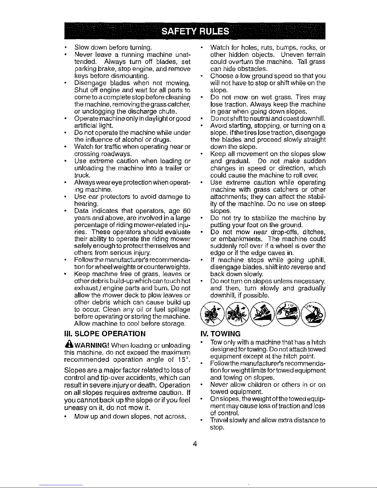
Do not turn on slopes unless necessary,
and then, turn slowly and gradually
downhill, if possible.
IV. TOWING
Tow only with a machine that has a hitch
designed for towing. Do not attach towed
equipment except at the hitch point.
Follow the manufacturer's recommenda-
tion for weight limits for towed equipment
and towing on slopes.
Never allow children or others in or on
towed equipment.
On slopes, the weight of the towed equip-
ment may cause loss of traction and loss
of control.
Travel slowly and allow extra distance to
stop.
Page 5
V. SERVICE
SAFE HANDLING OF GASOLINE
To avoid personal injury or property dam-
age, use extreme care in handling gasoline.
Gasoline is extremely flammable and the
vapors are explosive.
Extinguish all cigarettes, cigars, pipes,
and other sources of ignition.
• Use only approved gasoline container.
Never remove gas cap or add fuel with
the engine running.
Allow engine to coot before refueling.
Never fuel the machine indoors.
• Neverstore the machine orfuel container
where there is an open flame, spark, or
pilot light such as on a water heater or
other appliances.
• Never fill containers inside a vehicle or
on a truck or traiter bed with plastic liner.
Always place containers on the ground
away from your vehicle when filling.
• Remove gas-powered equipment from
the truck or trailer and refuel it on the
ground. Ifthis is not possible, then refuel
such equipment with a portable contai her,
rather than from a gasoline dispenser
nozzle.
Keep the nozzle in contact with the rim
of the fuel tank or container opening at
all times until fueling is complete. Do not
use a nozzle lock-open device.
Iffuel isspilled on clothing, change cloth-
ing immediately.
Never overfill fuel tank. Replace gas cap
and tighten securely.
GENERAL SERVICE
• Neveroperate machine in actosed area.
• Keep all nuts and bolts tightto ensure the
equipment is in safe working condition.
• Nevertamperwithsafetydevices. Never
interfere with the intended function of a
safety device or reduce the protection
provided by a safety device. Check there
proper operation regularly. NEVER oper-
ate a machine with a safety device that
does not function properly.
Keep machine free of grass, leaves, or
other debris build-up. Clean oil or fuel
spilFage and remove any fuel-soaked
debris. Allow machine to cool before
storing.
• If you strike a foreign object, stop and
inspectthe machine. Repair, ffnecessary,
before restarting.
Never make any adjustments or repairs
with the engine running.
• Check grass catcher components and the
discharge chute frequently and replace
with manufacturer's recommended parts,
when necessary.
Mower blades are sharp. Wrap the blade
or wear gloves, and use extreme caution
when servicing them.
• Check brakeoperation frequently. Adjust
and service as required.
• Maintain or replace safety and instruction
labels, as necessary.
Use ear protectors to avoid damage to hearing.
Always wear eye protection when operating machine.
Page 6
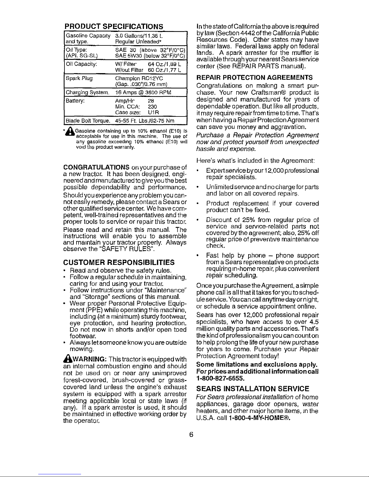
PRODUCT SPECIFICATIONS
Gasoline Capactty 3.0 Gallons!11,35 L
and type. RegularUn[eaded*
OiI Type: SAE 30 (above 32°F/0°C
(APt.SG-SL) SAE 5W30 (below 32_F/0°C
OilCapacity: W/FIEter' 64 Oz./1,89 L
W/out Filter 60 Oz./1,77 L
Spark Plug Champion RC12YC
(Gap..030"/0.76 ram)
Charging System. 16Amps @ 3600 RPM
Battery: Amp/Hr' 28
Min. CCA: 230
Case stze: UI R
Blade Bolt Torque. 45-55 Ft. Lbs./62-75 Nm
_bGasohne containing up to 10% ethanol (El0) ts
acceptabte for use in this machine. The use of
any gasoline exceedtng 10% ethanol (El0) will
vo=d the product warranty.
CONGRATULATIONS on your purchase of
a new tractor. It has been designed, engi-
neered and man ufactu red to give you the best
possible dependability and performance.
Should you experience any problem you can-
not easily remedy, please co ntact a Sears or
other qualifted service center. We have com-
petent, well-trained representatives and the
proper tools to service or repair this tractor.
Please read and retain this manual. The
instructions will enable you to assemble
and maintain your tractor properly. Always
observe the "SAFETY RULES".
CUSTOMER RESPONSIBILITIES
• Read and observe the safety rules.
• Follow a regularschedu[e in maintaining,
caring for and using your tractor.
• Follow instructions under"Maintenance"
and "Storage" sections of this manual.
• Wear proper Personal Protective Equip-
ment ('PPE) while operating this machine,
including (at a minimum) sturdy footwear,
eye protection, and hearing protection.
Do not mow in shorts and/or open toed
footwear.
• Always letsomeone knowyou are outside
mowing.
_kWARNING: This tractor is eq uipped with
an internal combustion engine and should
not be used on or near any unimproved
forest-covered, brush-covered or grass-
covered land unless the engine's exhaust
system is equipped with a spark arrester
meeting applicable local or state laws (if
any). If a spark arrester is used, it should
be maintained in effective working order by
the operator.
Inthe state of California the above isrequired
by law (Section 4442 of the California Public
Resources Code). Other states may have
similar laws. Federal laws apply on federal
lands. A spark arrester for the muffler is
availablethrough your nearest Sears service
center (See REPAIR PARTS manual).
REPAIR PROTECTION AGREEMENTS
Congratulations on making a smart pur-
chase. Your new Craftsman® product is
designed and manufactured for years of
dependable operation. But like all products,
it may require repair from timeto time. That's
when having a Repair Protection Agreement
can save you money and aggravation.
Purchase a Repair Protection Agreement
now and protect yourself from unexpected
hassle and expense.
Here's what's included in the Agreement:
, Expertservicebyour 12,000 professional
repair specialists.
° Un[imitedservJceand no charge for parts
and labor on all covered repairs.
Product replacement if your covered
product can't be fixed.
• Discount of 25% from regular price of
service and servtce-related parts not
covered by the agreement; also, 25% off
regular price of prevenWe maintenance
check.
• Fast help by phone - phone support
from a Sears representative on products
requiring tn-home repair, plus convenient
repair scheduling.
Once you purchase theAgreement, asimple
phone call is all that ittakes for you to sched-
ule service. You can call anytime day or nig ht,
or schedule a service appointment online.
Sears has over 12,000 professional repair
specialists, who have access to over 4.5
million quality parts and accessories. That's
the kind of profess ionalism you can count on
to help prolong the life of your new purchase
for years to come. Purchase your Repair
Protection Agreement today[
Some limitations and exclusions apply.
For prices and additional information call
1-800-827-6655.
SEARS INSTALLATION SERVICE
For Sears professional installation of home
appliances, garage door openers, water
heaters, and other major home items, Jnthe
U.S.A. call 1-800-4-MY-HOME®.
Page 7
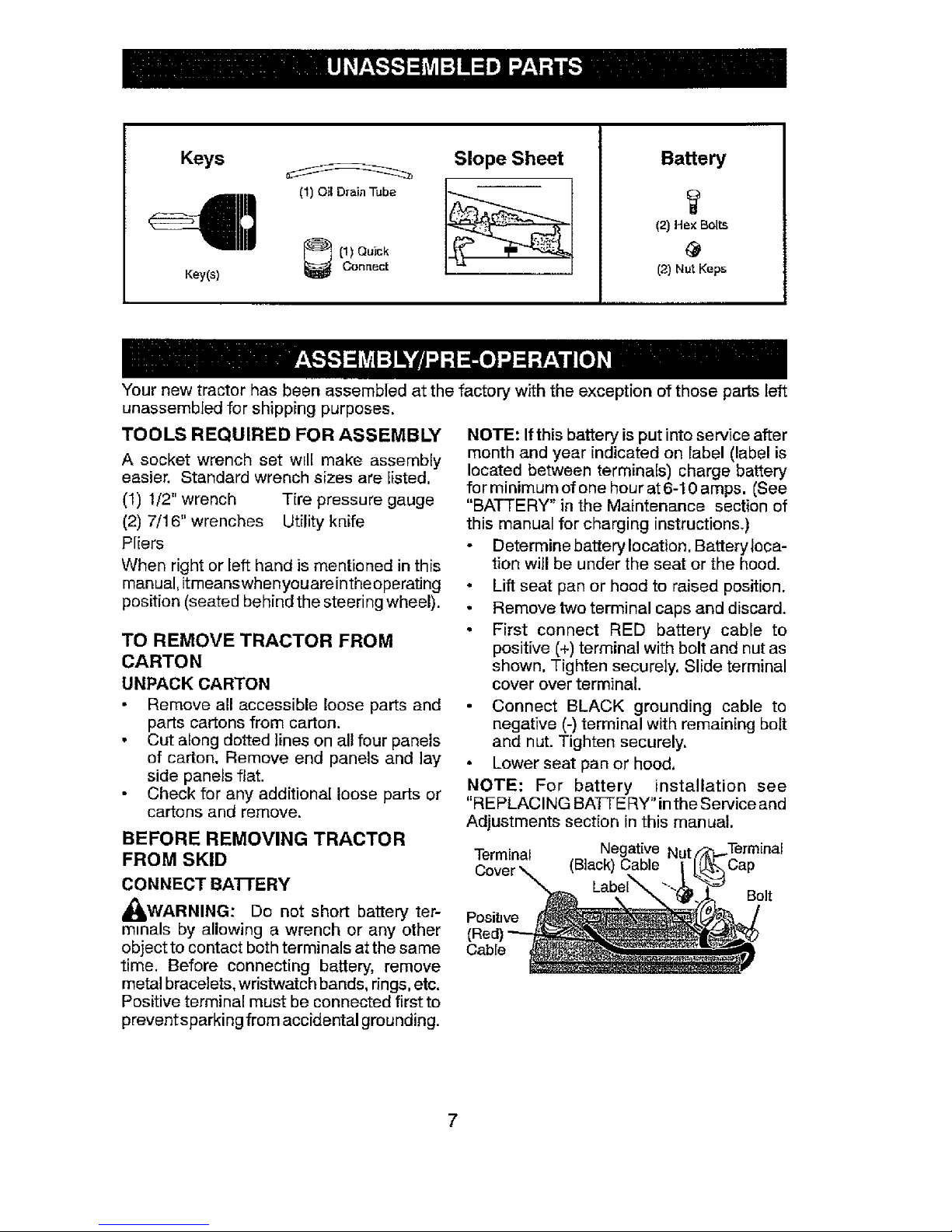
Keys _ Slope Sheet
[1) Quick
Key(s) Connect
Battery
(2) Hex Bolts
@
(2) Nut Keps
Your new tractor has been assembled at the factory with the exception of those parts left
unassembled for shipping purposes.
TOOLS REQUIRED FOR ASSEMBLY
A socket wrench set will make assembly
easier. Standard wrench sizes are f[sted,
(1) !/2" wrench Tire pressure gauge
(2) 7/16" wrenches Utility knife
Pliers
When right or left hand is mentioned in this
manual, itmeanswhenyou areinthe operating
position (seated behind the steering wheel).
TO REMOVE TRACTOR FROM
CARTON
UNPACK CARTON
Remove all accessible loose parts and
parts cartons from carton.
• Cut along dotted lines on all four panels
of carton. Remove end panels and lay
side panels flat.
Check for any additional loose parts or
cartons and remove.
BEFORE REMOVING TRACTOR
FROM SKID
CONNECT BA]-rERY
_WARNING: Do not short battery ter-
m=nals by allowing a wrench or any other
object to contact bothterminalsat thesame
time. Before connecting battery, remove
metalbracelets,wristwatch bands,rings,etc.
Positive terminal must be connected first to
prevent sparking from accidental grounding.
NOTE: If this battery isput into service after
month and year indicated on label (label is
located between terminals) charge battery
for minimum of one hour at 6-10 amps. (See
"BATTERY" in the Maintenance section of
this manual for charging instructions.)
Determine battery location. Battery loca-
tion will be under the seat or the hood.
• Lift seat pan or hood to raised position.
Remove two terminal caps and discard.
• First connect RED battery cable to
positive (+) terminal with bolt and nut as
shown. Tighten securely. Slide terminal
cover over terminal.
Connect BLACK grounding cable to
negative (-) terminal with remaining bolt
and nut. Tighten securely.
• Lower seat pan or hood.
NOTE: For battery installation see
"RE PLACING BATf'E RY" in the Service and
Adjustments section in this manual.
Terminal Negative N
Cover _ (Black) Cable Cap
Bolt
Positwe
Cable
7
Page 8
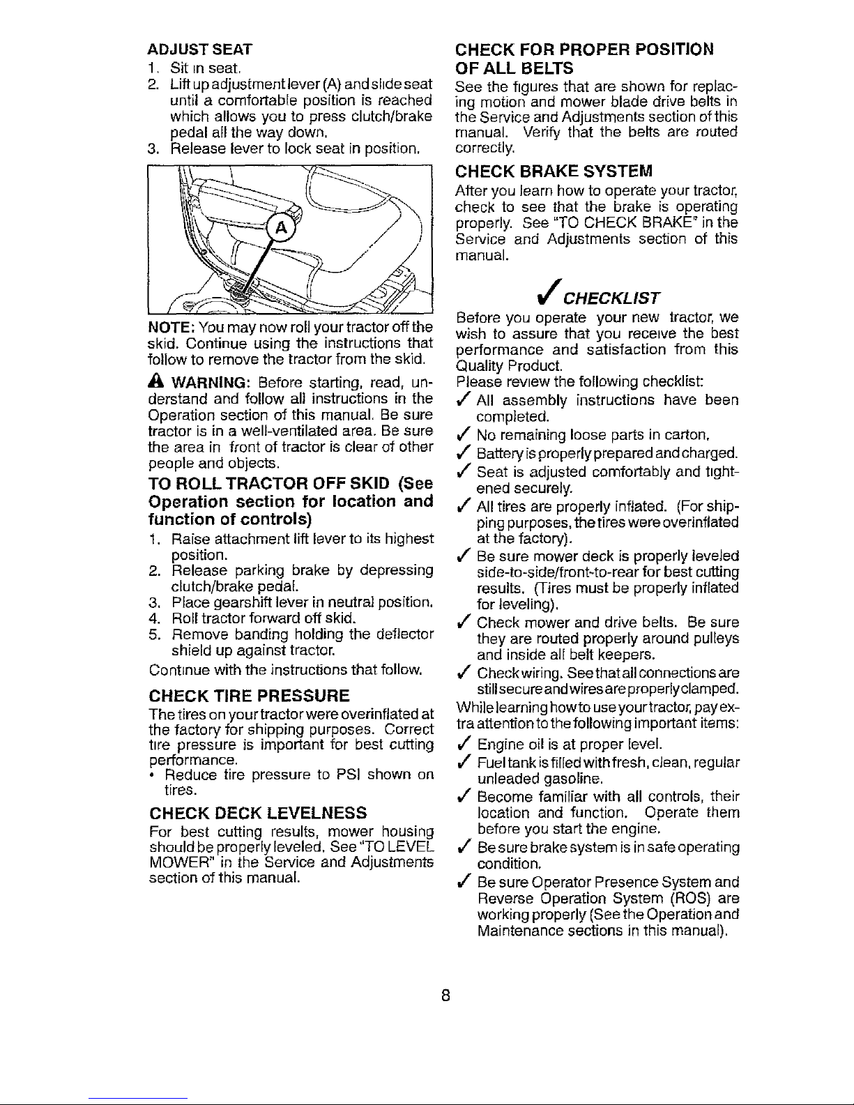
ADJUST SEAT
1. Sit In seat.
2. Lift up adjustment lever (A) and shde seat
until a comfortable position is reached
which allows you to press clutch/brake
pedal all the way down.
3. Release lever to lock seat in position.
NOTE: You may now roll your tractor off the
skid. Continue using the instructions that
follow to remove the tractor from the skid.
_1_WARNING: Before starting, read, un-
derstand and follow all instructions in the
Operation section of this manual. Be sure
tractor is in a well-ventilated area. Be sure
the area in front of tractor is clear of other
people and objects.
TO ROLL TRACTOR OFF SKID (See
Operation section for location and
function of controls)
1. Raise attachment lift lever to its highest
position.
2. Release parking brake by depressing
clutch/brake pedal.
3, Place gearshift lever in neutral position.
4. Roll tractor forward off skid.
5. Remove banding holding the deflector
shield up against tractor.
Continue with the instructions that follow.
CHECK TIRE PRESSURE
The tires on your tractor were overinftated at
the factory for shipping purposes. Correct
ttre pressure is important for best cutting
performance.
• Reduce tire pressure to PSI shown on
tires.
CHECK DECK LEVELNESS
For best cutting results, mower housing
should be properly leveled, See "TO LEVEL
MOWER" in the Service and Adjustments
section of this manual.
CHECK FOR PROPER POSITION
OF ALL BELTS
See the figures that are shown for replac-
ing motion and mower blade drive belts in
the Service and Adjustme nts section of this
manual. Verify that the belts are routed
correctly,
CHECK BRAKE SYSTEM
After you Jearn how to operate your tractor,
check to see that the brake is operating
properly. See "TO CHECK BRAKE" in the
Service and Adjustments section of this
manual.
_CHECKLIST
Before you operate your new tractor, we
wish to assure that you receive the best
performance and satisfaction from this
Quality Product.
Please revtew the following checklist:
,/All assembly instructions have been
completed.
J No remaining loose parts in carton,
J" Battery isproperly prepared and charged.
,/Seat is adjusted comfortably and ttght-
ened securely.
All tires are properly inflated. (For ship-
ping purposes, the tires were overinflated
at the factory).
,/" Be sure mower deck is properly leveled
side-to-side!fronbto-rear for best cutting
results. (Tires must be properly inflated
for leveling),
,/Check mower and drive belts, Be sure
they are routed properly around pulleys
and inside all belt keepers.
J Checkwiring. Seethatall connections are
stillsecureand wiresare properlyclamped.
While learning howte use yourtractor, pay ex-
tra attention to the following important items;
J' Engine oil is at proper level.
_/Fuel tank isfilledwithfresh, dean, regular
unleaded gasoline.
,/ Become familiar with all controls, their
location and function. Operate them
before you start the engine.
J" Be sure brake system is in safe operating
condition.
,/Be sure Operator Presence System and
Reverse Operation System (ROS) are
working properly (See the Operation and
Maintenance sections in this manual).
8
Page 9
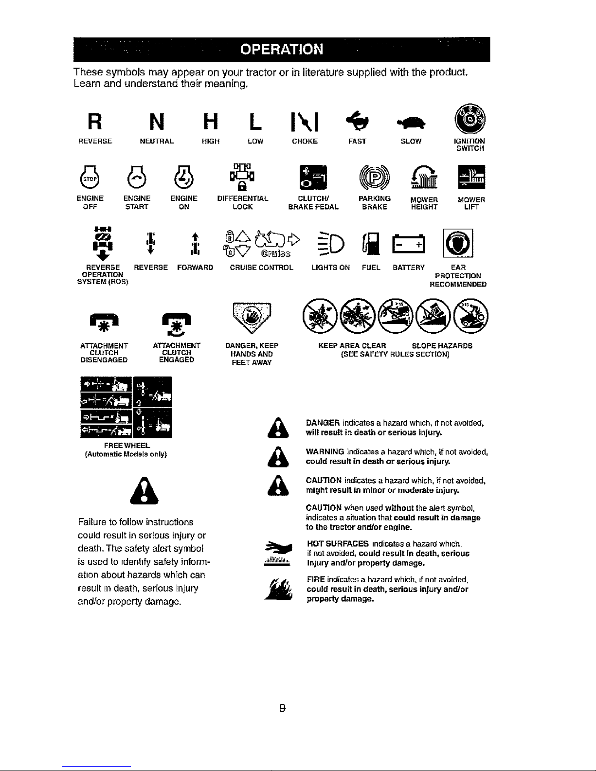
Thesesymbolsmayappearonyourtractororinliteraturesuppliedwiththeproduct.
Learnandunderstandtheirmeaning.
R N H L Ikl
REVERSE NEUTRAL HIGH LOW CHOKE FAST SLOW IGNITION
SWITCH
ENGINE ENGINE ENGINE DIFFERENTIAL
OFF START ON LOCK
m
CLUTCH] PARKING MOWER MOWER
BRAKE PEDAL BRAKE HEIGHT LIFT
REVERSE
OPERATION
SYSTEM (ROS)
REVERSE FORWARD CRUISE CONTROL LIGHTS ON FUEL BATTERY EAR
PROTECTION
RECOMMENDED
A'I-FACHMENT ATTACHMENT DANGER_ KEEP
CLUTCH CLUTCH HANDS AND
DISENGAGED ENGAGED FEET AWAY
®@@@@
KEEP AREA CLEAR SLOPE HAZARDS
{SEE SAFETY RULES SECTION)
FREEWHEEL
[Automatic Models only)
&
Failure to fellow instructions
could result in serious injury or
death. The safety alert symbol
is used to identify safety inform-
at_onabout hazards which can
result in death, serious injury
and/or property damage.
&
&
&
DANGER indicatesa hazard which, Jfnot avoided,
will result in death or serious injury.
WARNING indicates a hazard which, if not avoided,
could result in death or serious injury.
CAUTION indicates a hazard which, if not avoided,
might result in minor oz- moderate injury.
CAUTION when used without thealert symbol,
indicates a situation that could result in damage
to the tractor and/or engine.
HOT SURFACES indicates a hazard wh=ch,
if net avoided, could result In death, serious
injury and/or property damage.
FIRE indicates a hazard which, if not avoided,
could result in death, serious injury and/or
property damage.
Page 10
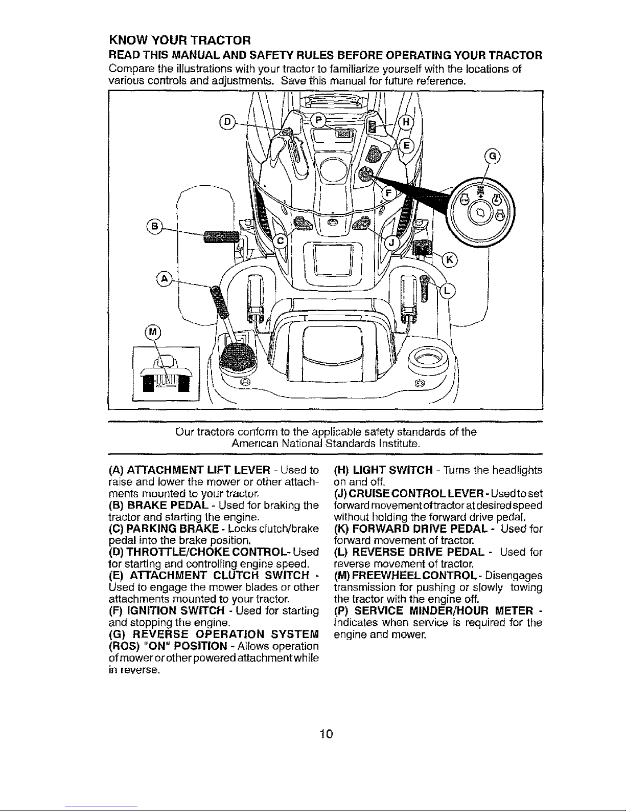
KNOW YOUR TRACTOR
READ THIS MANUAL AND SAFETY RULES BEFORE OPERATING YOUR TRACTOR
Compare the ilJustrationswith your tractor to familiarize yourself withthe locations of
various controls and adjustments. Save this manual for future reference.
@
Our tractorsconform to the applicable safety standards of the
Amencan National Standards Institute.
(A) ATTACHMENT LIFT LEVER - Used to
raise and lower the mower or other attach-
ments mounted to your tractor,
(B) BRAKE PEDAL - Used for braking the
tractor and starting the engine.
(C) PARKING BRAKE - Locks clutch/brake
pedal into the brake position.
(D) THROTTLE/CHOKE CONTROL- Used
for starting and controlling engine speed.
(E) ATTACHMENT CLUTCH SWITCH -
Used to engage the mower blades or other
attachments mounted to your tractor.
(F) IGNITION SWITCH - Used for starting
and stopping the engine,
(G) REVERSE OPERATION SYSTEM
(ROS) "ON" POSITION - Allows operation
of mower or other powered attachmentwhile
in reverse.
(H) LIGHT SWITCH - Turns the headlights
on and off.
(J) CRUISE CONTROL LEVER- Used to set
forward movement of tractor atdesired speed
without holding the forward drive pedal.
(K) FORWARD DRIVE PEDAL - Used for
forward movement of tractor.
(L) REVERSE DRIVE PEDAL - Used for
reverse movement of tractor.
(M) FREEWHEEL CONTRO L- Disengages
transmission for pushing or slowly towing
the tractor with the engine off.
(P) SERVICE MINDER/HOUR METER -
indicates when service is required for the
engine and mower.
10
Page 11

The operation of any tractor can result in foreign objects thrown intol
the eyes, which can result in severe eye damage. Always wear safety_
glasses or eye shields while operating your tractor or performing any1
adjustments or repairs. We recommend standard safety glasses ora I
wide vision safety mask worn over spectacles. |
HOW TO USE YOUR TRACTOR
TO SET PARKING BRAKE
Your tractor is equipped with an operator
presence sensing switch. When engine is
ru nning, any attempt bythe operator to leave
the seat without first setting the parking brake
will shut off the engine.
1, Depress brake pedal (B) allthe way down
and hold.
2. Pull parking brake lever (C) up and hold,
release pressure from brake pedal (B),
then release parking brake lever. Pedal
should remain in brake position. Make
sure parking brake will hold tractorsecure.
IMPORTANT: Leaving the ignition switch in
any position other than "STOP" will cause
the battery to discharge and go dead.
NOTE: Under certain conditions when tractor
is standing idle with the engine running, hot
engine exhaust gases may cause "brown-
ing" of grass. To eliminate this possibility,
always stop engine when stopping tractor
on grass areas.
CAUTION: Always stop tractor com-
pletely, as described above, before leaving
the operator's position.
TO USE THRO'I'rLE CONTROL
Always operate engine at full speed (fast).
• Operating engine at less than full speed
(fast) reduces engine's operating effi-
ciency.
• Pull speed (fast) offers the best mower
performance.
STOPPING
MOWER BLADES -
• To stop mower blades, move attachment
clutch control to the disengaged position.
GROUND DRIVE -
• To stop ground drive, depress brake pedal
all the way down.
IMPORTANT: Forward and reverse drive
pedals return to neutral position when not
depressed.
ENGINE -
• Move throttle control to slow position.
NOTE: Failure to move throttle control
to slow position and allowing engine to
idle before stopping may cause engine to
"backfire".
• Turn ignition key to "STOP" position and
remove key. Always remove key when
leaving tractor to prevent unauthorized
use.
• Never use choke to stop engine.
TO MOVE FORWARD AND BACKWARD
The direction and speed of movement
is controlled by the forward and reverse
drive pedals.
1. Start tractor and release parking brake.
2. Slowlydepressforward (K) orreverse (L)
drive pedal to begin movement. Ground
speed increases the further down the
pedal is depressed.
II
11
Page 12
TO USE CRUISE CONTROL
The cruise control feature can be used for
forward travel only.
SYSTEM CHARACTERISTICS
The cruise control should only be used
whtle mowing or transporting on relatively
smooth, straight surfaces. Other conditions
such as trimming at slow speeds may cause
the cruise control to disengage. Do not use
the cruise control on slopes, rough ternan
or while trimmimg or turning.
• With forward drive pedal (K) depressed to
desired speed, pull cruise control lever (J)
up and hold while lifting your foot off the
pedal, then release the lever.
To disengage the cruise control, depress the
brake pedal or tap on forward drive pedal,
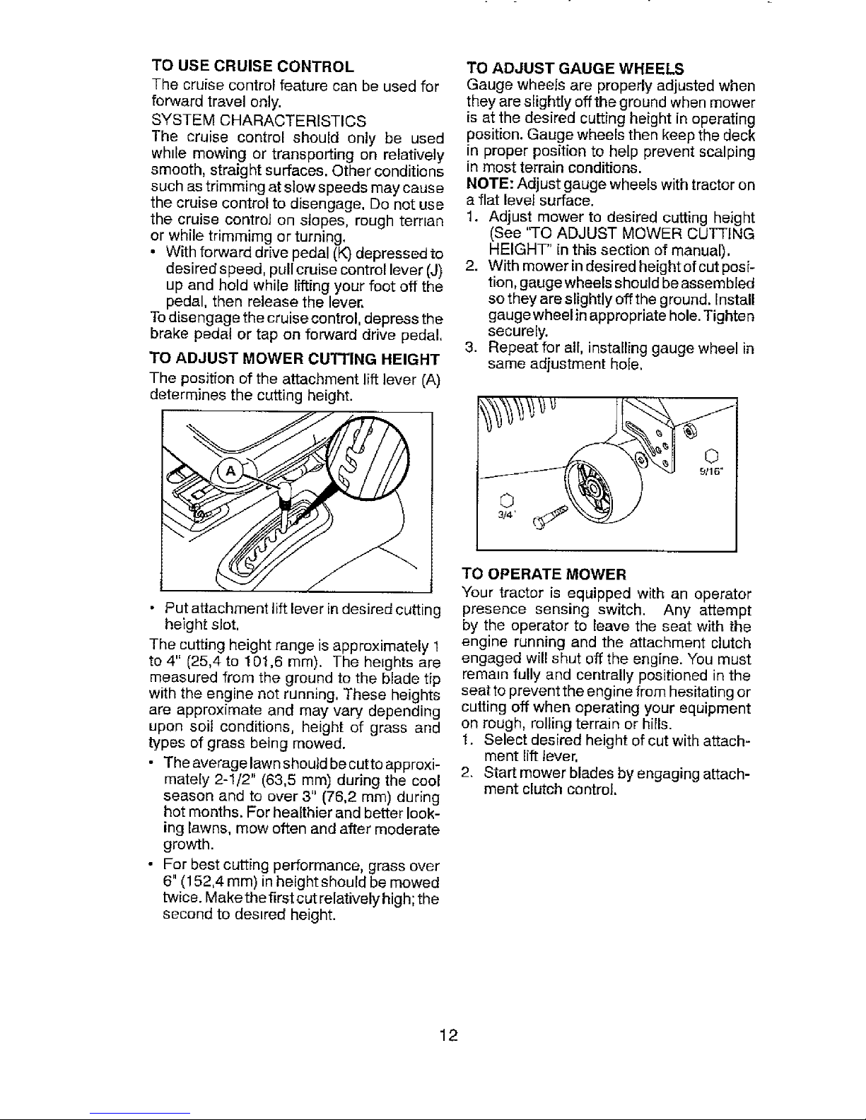
TO ADJUST MOWER CUTTING HEIGHT
The position of the attachment lift lever (A)
determines the cutting height.
• Put attachment lift lever in desired cutting
height slot,
The cutting height range is approximately 1
to 4" (25,4 to 101,6 ram). The heights are
measured from the ground to the blade tip
with the engine not running, These heights
are approximate and may vary depending
upon soil conditions, height of grass and
types of grass being mowed.
• The average lawn should be cutto approxi-
mately 2-1/2" (63,5 mm) during the cool
season and to over 3" (76,2 mm) during
hot months. For healthier and better look-
ing lawns, mow often and after moderate
growth.
• For best cutting performance, grass over
6" (152,4 mm) in height should be mowed
twice. Make the first cut relatively high; the
second to destred height.
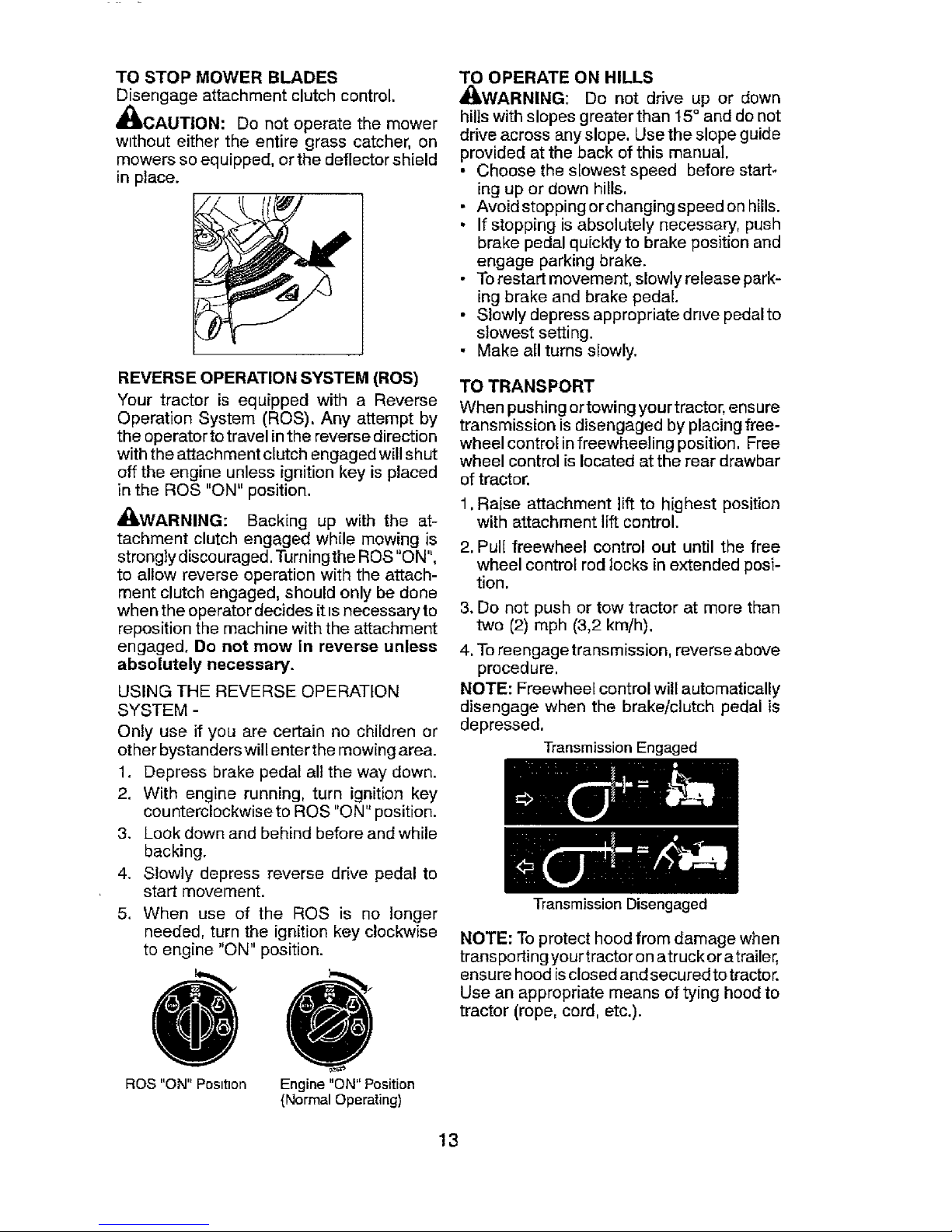
TO ADJUST GAUGE WHEELS
Gauge wheels are properly adjusted when
they are slightly off the ground when mower
is at the desired cutting height in operating
position. Gauge wheels then keep the deck
in proper position to help prevent scalping
in most terrain conditions.
NOTE: Adjust gauge wheels with tractor on
a flat level surface.
1. Adjust mower to desired cutting height
(See "TO ADJUST MOWER CUTTING
HEIGHT" in this section of manual).
2. With mower in desired heightofcut posi-
tion, gauge wheels should be assembled
so they are slightly off the ground. Install
gaugewheel in appropriate hole. Tighten
securely.
3. Repeat for air, installing gauge wheel in
same adjustment hole.
TO OPERATE MOWER
Your tractor is equipped with an operator
presence sensing switch. Any attempt
by the operator to feave the seat with the
engine running and the attachment clutch
engaged will shut off the engine. You must
remain fully and centrally positioned in the
seat to prevent the engine from hesitating or
cutting off when operating your equipment
on rough, rolling terrain or hills.
t. Select desired height of cut with attach-
ment lift lever.
2. Start mower blades by engaging attach-
ment clutch control.
12
Page 13
TO STOP MOWER BLADES
Disengage attachment clutch control.
_CAUTION: Do not operate the mower
w_thout either the entire grass catcher, on
mowers so equipped, or the deflector shield
in place.
REVERSE OPERATION SYSTEM (ROS)
Your tractor is equipped with a Reverse
Operation System (ROS). Any attempt by
the operator to travel in the reverse direction
with the attachment clutch engaged will shut
off the engine unless ignition key is placed
in the ROS "ON" position.
_(_WARNING: Backing up with the at-
tachment clutch engaged while mowing is
strongly discouraged. Turningthe ROS "ON",
to allow reverse operation with the attach-
ment clutch engaged, should only be done
when the operator decides it is necessary to
reposition the machine with the attachment
engaged, Do not mow in reverse unless
absolutely necessary.
USING THE REVERSE OPERATION
SYSTEM -
Only use if you are certain no children or
other bystanders will enter the mowing area.
1. Depress brake pedal all the way down.
2. With engine running, turn ignition key
counterclockwise to ROS "ON" position.
3. Look down and behind before and while
backing.
4. Slowly depress reverse drive pedal to
start movement.
5. When use of the ROS is no longer
needed, turn the ignition key clockwise
to engine "ON" position.
ROS "ON" Position
Engine "ON" Position
{Normal Operating)
TO OPERATE ON HILLS
_WARNING: Do not drive up or down
hills with slopes greater than 15 ° and do not
drive across any slope. Use the slope guide
provided at the back of this manual.
• Choose the s[owest speed before start-
ing up or down hills.
• Avoid stopping orchanging speed on hills.
• If stopping is absolutely necessary, push
brake pedal quickly to brake position and
engage parking brake.
• To restart movement, slowly release park-
ing brake and brake pedal.
• Slowly depress appropriate drive pedalto
slowest setting.
• Make all turns s[owly.
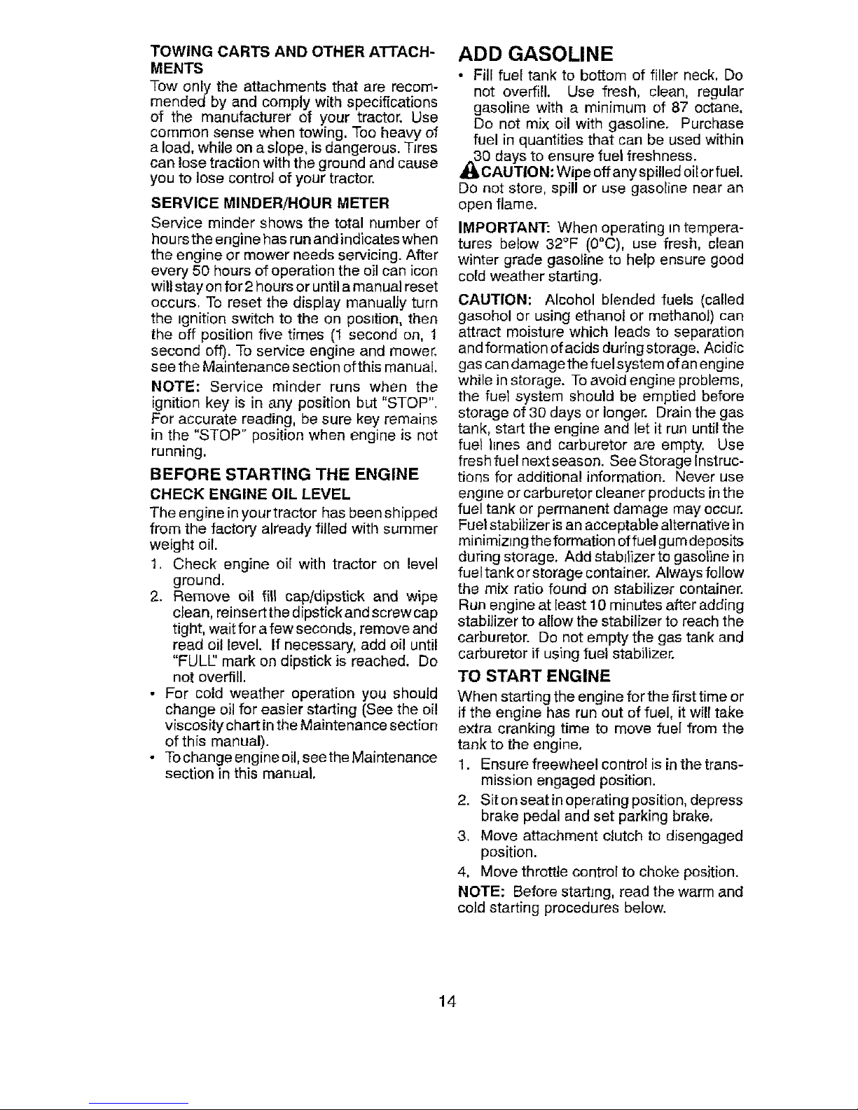
TO TRANSPORT
When pushing or towing your tractor, ensure
transmission is disengaged by placing free-
wheel control infreewheeling position. Free
wheel control is located at the rear drawbar
of tractor.
1. Raise attachment lift to highest position
with attachment lift control.
2, Pul[ freewheel control out until the free
wheel control rod locks in extended posi-
tion,
3, Do not push or tow tractor at more than
two (2) mph (3,2 kin/h).
4. To ree ngage transmission, reverse above
procedure.
NOTE: Freewheel control will automatically
disengage when the brake/clutch pedal is
depressed.
Transmission Engaged
Transmission Disengaged
NOTE: Toprotect hood from damage when
transporting yourtractor on atruckor atrailer,
ensure hood isclosed and secured totractor.
Use an appropriate means of tying hood to
tractor (rope, cord, etc.).
13
Page 14
TOWING CARTS AND OTHER A'I-I'ACH-
MENTS
Tow only the attachments that are recom-
mended by and comply with specifications
of the manufacturer of your tractor. Use
common sense when towing. Too heavy of
a load, while on a slope, is dangerous. Tires
can lose traction with the ground and cause
you to lose control of your tractor.
SERVICE MINDER/HOUR METER
Service minder shows the total number of
hours the engine has run and indicates when
the engine or mower needs servicing. After
every 50 hours of operation the oil can icon
will stay on for 2 hours or until a manual reset
occurs. To reset the display manually turn
the _gnition switch to the on pos=tion, then
the off position five times (1 second on, 1
second off). To service engine and mower.
see the Maintenance section of this manual.
NOTE: Service minder runs when the
ignition key is in any position but "STOP".
For accurate reading, be sure key remains
in the "STOP" position when engine is not
running.
BEFORE STARTING THE ENGINE
CHECK ENGINE OIL LEVEL
The engine inyour tractor has been shipped
from the factory already filled with summer
weight oil.
1. Check engine oil with tractor on level
ground.
2. Remove oil fill cap/dipstick and wipe
clean, reinsertthe dipstick and screw cap
tight, wait fer a few seconds, remove and
read oil level. If necessary, add oil until
"FULL' mark on dipstick is reached. Do
not overfill.
• For cold weather operation you should
change oil for easier starting (See the oi!
viscosity chart in the Maintenance section
of this manual).
• Tochange engineoil,seethe Maintenance
section in this manual.
ADD GASOLINE
• Fill fuel tank to bottom of filler neck. Do
not overfill. Use fresh, clean, regular
gasoline with a minimum of 87 octane.
Do not mix oil with gasoline. Purchase
fuel in quantities that can be used within
0 days to ensure fuel freshness.
CAUTIO N: Wipe off any spilled oilor fuel.
Do not store, spill or use gasoline near an
open flame.
IMPORTANT: When operating in tempera-
tures below 32°F (0°C), use fresh, clean
winter grade gasoline to help ensure good
cold weather starting.
CAUTION: Alcohol blended fuels (called
gasohol or using ethanol or methanol) can
attract moisture which leads to separation
and formation of acids during storage. Acidic
gas can damage the fuel system of an engine
while in storage. To avoid engine problems,
the fuel system should be emptied before
storage of 30 days or longer. Drain the gas
tank, start the engine and let it run until the
fuel hnes and carburetor are empty, Use
fresh fuel next season. See Storage Instruc-
tions for additional information. Never use
engine or carburetor cleaner products in the
fuel tank or permanent damage may occur.
Fuel stabilizer is an acceptable alternative in
minimiz=ng the formation offuel gum deposits
during storage. Add stabilizer to gasoline in
fuel tank or storage container. Always follow
the mix ratio found on stabilizer container.
Run engine at least 10 minutes after adding
stabilizer to allow the stabilizer to reach the
carburetor. Do not empty the gas tank and
carburetor if using fuel stabilizer.
TO START ENGINE
When starting the engine for the first time or
if the engine has run out of fuel, it will take
extra cranking time to move fuel from the
tank to the engine.
1. Ensure freewheel control is in the trans-
mission engaged position.
2. Sit on seat in operating position, depress
brake pedal and set parking brake.
3. Move attachment clutch to disengaged
position.
4. Move throttle control to choke position.
NOTE: Before starting, read the warm and
cold starting procedures below.
14
Page 15
5. Insert key into ignition and turn key
clockwise to start position and release
key as soon as engine starts. Do not run
starter contin uously for more than fifteen
seconds per minute. If the engine does
not start after several attempts, move
throttle control to fast position, wait a
few minutes and try again. If engine still
does not start, move the throttle control
back to the choke position and retry.
WARM WEATHER STARTING
(50°F (10°C) and above)
6. When engine starts, move the throttle
control to the fast position.
• The attachments and ground drive
can now be used. If the engine does
not accept the load, restart the engine
and allow it to warm up for one minute
using the choke as described above.
COLD WEATHER STARTING
(50°F (10°C) and below)
6. When engine starts, leaveth rott[e control
in choke position until engine warms up
and begins to run roughly. Once rough
running begins, immediately move the
throttle control to the fast position. Engine
warm-up maytake from several seconds
to several minutes (the colder the tem-
perature, the longer the warm-up).
AUTOMATIC TRANSMISSION WARM UP
Before driving the unit in cold weather, the
transmission should be warmed up as fol-
lows:
1. Ensure the tractor is on level ground.
2. Release the parking brake and let the
brake slowly return to operating position.
3. Allow one minute for transmission to
warm up. This can be done during the
engine warm up period.
• The attachments can also be used
du ringthe engine warm-up period after
the transmission has been warmed up.
MOWING TIPS
• DO NOT use tire chains when the mower
housing is attached to tractor.
• Mower should be properly leveled for best
mowing performance. See "TO LEVEL
MOWER HOUSING" in the Service and
Adjustments section of this manual.
• The left hand side of mower should be
used for trimming.
• Driveso that clippings are discharged onto
the area that has already been cut. Have
the cut areato the right of the tractor. This
will result in a more even distribution of
clippings and more uniform cutting.
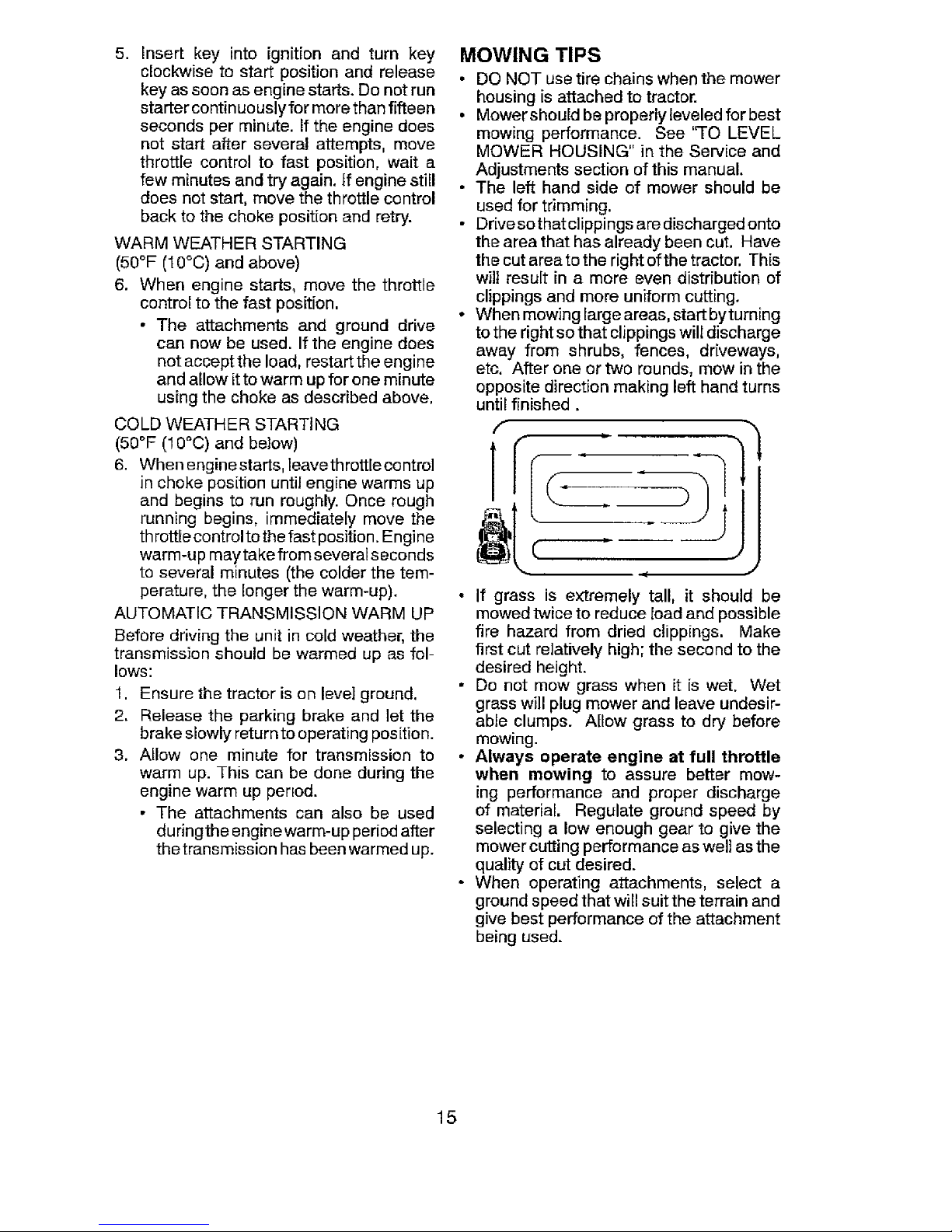
• When mowing large areas, start byturning
to the right so that clippings will discharge
away from shrubs, fences, driveways,
etc. After one or two rounds, mow in the
opposite direction making left hand turns
until finished.
r L
• If grass is extremely tall, it should be
mowed twice to reduce load and possible
fire hazard from dried clippings. Make
first cut relatively high; the second to the
desired height.
• Do not mow grass when it is wet. Wet
grass will plug mower and leave undesir-
able clumps. Allow grass to dry before
mowing.
• Always operate engine at full throttle
when mowing to assure better mow-
ing performance and proper discharge
of material. Regulate ground speed by
selecting a low enough gear to give the
mower cutting performance as well as the
quality of cut desired.
• When operating attachments, select a
ground speed that will suit the terrain and
give best performance of the attachment
being used.
15
Page 16

BFJ:ORE EVERy EVEn EVeR_ L_t=ERY EU_Ry BEFORE
MAINTENANCE SCHEDULE _=. _ =_ so ,_o _o. STORagE
USE HOURS HOURS HOUR_ HOURS
iii ii i
Check BrakB Opera,on V" V'
Choc_ T=re Press_[e V _ V r
T ChEck Operator Presence al_l ROS Systems V p
R ..,Cheo_to, L.... Fe_t ..... If I_, IV#'
A ChucktRepJac_ Mower B_des
C Lu_nc=l;onchat _
T Ch_ck Batte_ Level
O Cle_n Battery _p Termmal_ _ I_" "
R G_ Debris off Steering Flute
Gheck Mower Levelness V"
Check V- Be IL_
Check En_tlae Od Level ii _ V _
Chugs Eng_np O_ (modek w=th o=ltilted _ =
Ch_r_ge Eng{ne O_1(mode_ wdhout o_1flitst) II_t _. if
E cleanAi_F=_et
Cle_n Air Scleen
Inspect MLlffledSpa[k _rfeste; V _
_4eptece Or_ Fil_er I='feq.,ppe;_ fm¢_1
E Cle_n Engine Goolmg F_ns
Replace Spark Plug _ l
Rep_ce Air Filter Paper Catr=_ge
Replace Fuel Filter V'
GENERAL RECOMMENDATIONS
The warranty on this tractor does not cover
items that have been subjected to operator
abuse or negligence. To receive full value
from the warranty, operator must maintain
tractor as instructed in this manual.
Some adjustments will need to be made
periodically to properly maintain your tractor.
At least once a season, check to see if
you should make any of the adjustments
described in the Service and Adjustments
section of this manual.
• At least once a year you should repIace
the spark plug, clean or replace air filter,
and check blades and belts for wear. A
new spark plug and c[ean air filter assure
proper air-fuel mixture and heJp your en-
gine run better and last longer.
BEFORE EACH USE
1. Check engine oil level.
2. Check brake operation.
3. Check tire pressure.
4. Check operator presence and
ROS systems for proper operation.
5. Check for loose fasteners.
LUBRICATION CHART
_)Steering Pivot Bolts
Spindle----m_-i_ r-_ @ Spindle
Zerk ___#. =_'_L Zerk
Front _ WI*'_"" Z _''I;_j_" 1(1(_Front Wheel
Wheel ._ .7_:'"_ Bearing Zerk
Bearing ,.-_-'_" I
Zerk - /./['l - _._
._ '::_ _ _, 2"_ Engine
Gear I I :t_:!ir-__k: l IX
Teeth I I \ '-'_" / II \
k.J" " 1._ _- Mandrel
Zerks
(_)General Purpose Grease
@)RefertoMaintenance "ENGINE" Section.
IMPORTANT: Do not oil or grease the pivot
points which have special nylon bearings,
Viscous lubricants will attract dust and dirt
that will shorten the life ofthe self-lubricating
bearings. If you feelthey must belubricated,
use only a dry, powdered graphite type
lubricant sparingly.
16
Page 17
TRACTOR
Always observe safety rules when perform-
ing any maintenance.
BRAKE OPERATION
If tractor requires more than 5 feet (1,5 m)
to stop at highest speed In highest gear on
a level, dry concrete or paved surface, then
brake must be serviced. (See "TO CHECK
BRAKE" in the Service and Adjustments
section of this manual).
TIRES
• Maintain proper air pressure in all tires
(See the side of tires for proper PSl.)
• Keep tires free of gasoline, oil, or insect
control chemicals which can harm rubber.
• Avoid stumps, stones, deep ruts, sharp
objects and other hazards that may cause
tire damage.
NOTE: To seal tire punctures and prevent
flat tires due to slow leaks, tire sealant may
be purchased from your local parts dearer.
Tire sealant also prevents tire dry rot and
corrosion.
OPERATOR PRESENCE SYSTEM AND
REVERSE OPERATION SYSTEM (ROS)
Be sure operator presence and reverse
operation systems are working properly. If
your tractor does not function as described,
repair the problem immediately.
• The engine should not start unless the
brake pedal is fully depressed, and the
attachment clutch control is in the disen-
gaged position.
CHECK OPERATOR PRESENCE SYSTEM
• When the engine is running, any attempt
by the operator to leave the seat without
first setting the parking brake should shut
off the engine.
• When the engine is running and the at-
tachment clutch is engaged, any attempt
by the operator to leave the seat should
shut off the engine.
• The attachmentclutch should neveroper-
ate unless the operator is in the seat.
CHECK REVERSE OPERATION (ROS)
SYSTEM
• When the engineis running with the ignition
switch inthe engine "ON" position and the
attachment clutch engaged, any attempt
by the operator to drive in reverse should
shut off the engine.
• When the engine is running with the ignition
switch in the ROS "ON" position and the
attachment clutch engaged, any attempt
by the operator to drive in reverse should
NOT shut off the engine.
Ros "On" Engine "On" Position
Position (Normal Operating)
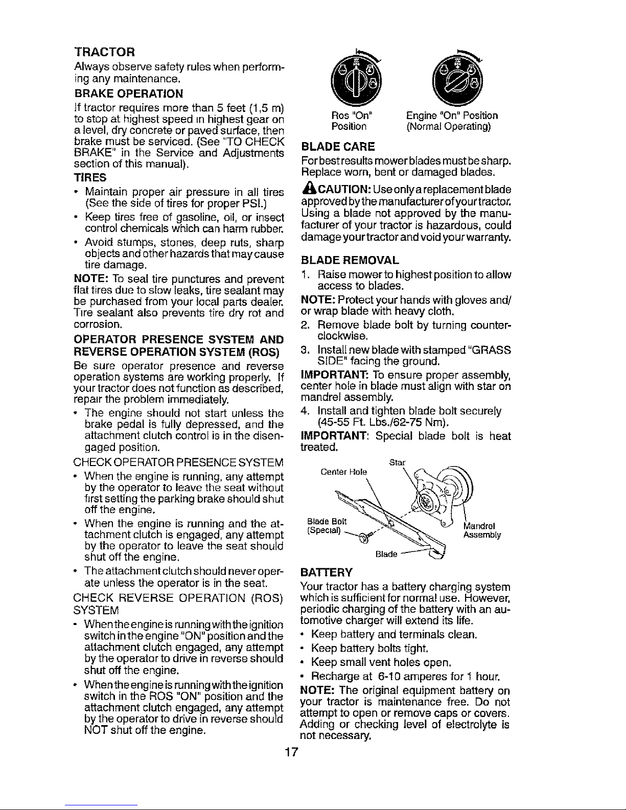
BLADE CARE
Forbestresults mower blades must besharp.
Replace worn, bent or damaged blades.
_I_CAUTION: Use only a replacement blade
approved bythe manufacturer ofyourtractor.
Using a blade not approved by the manu-
facturer of your tractor is hazardous, could
damage yourtractor and void yourwarranty.
BLADE REMOVAL
1. Raise mower tohighestposition to allow
access to blades.
NOTE: Protectyourhands withglovesand!
or wrap blade with heavy cloth,
2, Remove blade bolt by turningcounter-
cJockwise.
3. Install new bladewith stamped"GRASS
SIDE" facing the ground.
IMPORTANT: Toensure proper assembly,
center hole in blade must align with star on
mandrel assembly.
4. Install and tighten blade bolt secure[y
(45-55 Ft. Lbs./62-75 Nm).
IMPORTANT: Special blade bolt is heat
treated.
Star
Center Hole
Blade Bolt Mandrel
(Special) _. Assembfy
Blade
BATTERY
Your tractor has a battery charging system
which is sufficient for normal use. However,
periodic charging of the battery with an au-
tomotive charger will extend its life.
• Keep battery and terminals clean.
• Keep battery bolts tight,
• Keep small vent holes open.
• Recharge at 6-10 amperes for I hour.
NOTE: The original equipment battery on
your tractor is maintenance free. Do not
attempt to open or remove caps or covers.
Adding or checking level of electrolyte is
not necessary.
17
Page 18
TO CLEAN BATTERY AND TERMINALS
Corrosion and dirt on the battery and terminals
can cause the battery to "leak" power.
1. Remove terminal guard.
2. Disconnect BLACK battery cable first
then RED battery cable and remove
battery from tractor.
3. Rinse the battery with plain water and
dry.
4. Clean terminals and battery cable ends
with wire brush until bright.
5, Coatterminals with grease orpetroleum
jelly,
6. Reinstall battery (See "REPLACING
BATTERY" in the Service and Adjust-
ments section of this manual).
TRANSAXLE MAINTENANCE
The transaxle was sealed at the factory and
fluid maintenance is not required for the life
of the transaxte. Should the transaxle ever
leak or require servicing, contact your near-
est Sears or other qualified service center.
V-BELTS
CheckV-belts for deterioration and wear after
100 hours of operation and replace if neces-
sary. The belts are not adjustable. Replace
belts if they begin to shp from wear.
ENGINE
TO CHANGE ENGINE OIL
Determine temperature range expected
before oil change. All oil must meet API
service classification SG-SL.
Ensure tractor is on revel surface.
• Oil will drain more freely when warm.
• Catch oil in a suitable container.
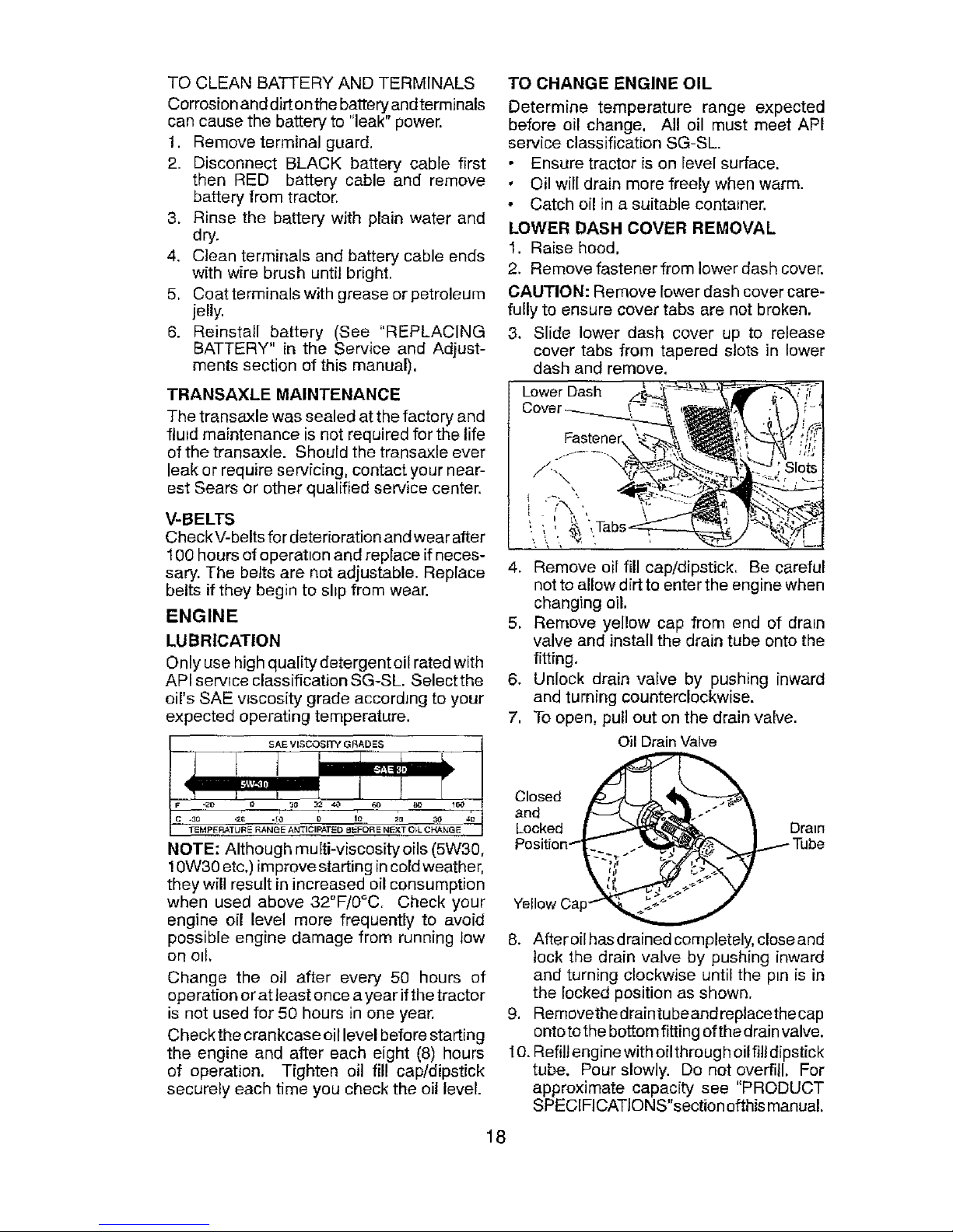
LOWER DASH COVER REMOVAL
1. Raise hood,
2. Remove fastener from lower dash cover.
CAUTION: Remove lower dash cover care-
fully to ensure cover tabs are not broken.
3. Slide lower dash cover up to release
cover tabs from tapered slots in lower
5,
LUBRICATION
Only use high quality detergent oil rated with
API service classification SG-SL. Selectthe 6.
oil's SAE wscosity grade accordJng to your
expected operating temperature. 7,
1
_rE M PE RAT_'E RANGE AN'I'IC_A'FE D 8 _"FOR E N_ 13_L C}_NG E
1
NOTE: Although multi-viscosityoils (5W30,
! 0W30 etc.) improve starting incord weather,
they will result in increased oil consumption
when used above 32°F/0°C. Check your
engine oil level more frequently to avoid
possible engine damage from running low
or] o11,
Change the oil after every 50 hours of
operation or at least once a year if the tractor
is not used for 50 hours in one year.
Check the crankcase oil level before starting
the engine and after each eight (8) hours
of operation. Tighten oil fill cap/dipstick
securely each time you check the oil level.
Remove oil fill cap/dipstick, Be careful
not to allow dirt to enter the engine when
changing oil.
Remove yellow cap from end of drain
valve and install the drain tube onto the
fitting.
Unlock drain valve by pushing inward
and turning counterclockwise.
To open, pull out on the drain valve.
Oil Drain Valve
O'n° e0
Locked __ _Tube
Position_
!
Yellow Cap_
8. Afleroilhasdrainedcompletely, closeand
lock the drain valve by pushing inward
and turning clockwise until the pin is in
the locked position as shown.
9, Removethe draintu be and replace the cap
onto to the bottom fitting of the drain valve.
t O.Refill engine with oil through oil fill dipstick
tube. Pour slowly. Do not overfill. For
approximate capacity see "PRODUCT
SPECIFICATIONS"section ofthis manual.
18
Page 19
11,Usegaugeonoilfillcap/dipstickforcheck-
inglevel,Ensuredipstickcapistightened
securelyforaccuratereading.Keepoilat
"FULE'lineondipstick.Tightencaponto
thetubesecurelywhenfinished.
ENGINEOILFILTER
Replacetheengineoilfiltereveryseasonor
everyotheroilchangeifthetractorisused
morethan100hoursinoneyear.
NOTE:Ifneeded,removelowerdashcovers
usingstepsfrom"Lowerdashcoverremoval"
sectionofthismanual.
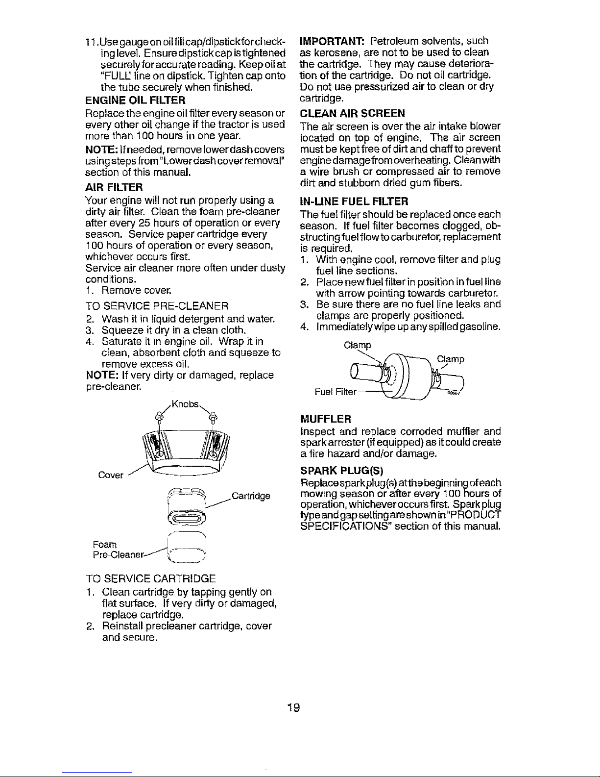
AIR FILTER
Your engine will not run properly using a
dirty air filter. Clean the foam pre-cleaner
after every 25 hours of operation or every
season. Service paper cartridge every
100 hours of operation or every season,
whichever occurs first.
Service air cleaner more often under dusty
conditions.
1. Remove cover.
TO SERVICE PRE-CLEANER
2. Wash it in liquid detergent and water.
3. Squeeze it dry in a clean cloth,
4, Saturate it in engine oi1. Wrap it in
clean, absorbent cloth and squeeze to
remove excess oil,
NOTE: If very dirty or damaged, replace
pro-cleaner.
1 Cartridge
f _
Pre-Cleanert f !_- _'r
TO SERVICE CARTRIDGE
1. Clean cartridge by tapping gently on
flat surface. If very dirty or damaged,
replace cartridge.
2, Reinstall precleaner cartridge, cover
and secure.
IMPORTANT: Petroleum solvents, such
as kerosene, are notto be used to clean
the cartridge. They may cause deteriora-
tion of the cartridge. Do not oil cartridge.
Do not use pressurized air to clean or dry
cartridge.
CLEAN AIR SCREEN
The air screen is over the air intake blower
located on top of engine, The air screen
must bekept free of dirt and chaff to prevent
enqine damagefrom overheating. Cleanwith
a wire brush or compressed air to remove
dirt and stubborn dried gum fibers.
IN-LINE FUEL FILTER
The fuel filter should be replaced once each
season. If fuel filter becomes clogged, ob-
structing fuel flow to carburetor, replacement
is required.
1. With engine cool, remove filter and plug
fuel line sections.
2. Place newfuetfilter in position infuel line
with arrow pointing towards carburetor.
3. Be sure there are no fuel line leaks and
clamps are properly positioned.
4. Immediatelywipe up anyspilledgaso[ine.
Clamp
""-..,_x----_ Clamp
Fuel Filte_
MUFFLER
Inspect and replace corroded muffler and
spark arrester (if equipped) as it could create
a fire hazard and/or damage.
SPARK PLUG(S)
Replacesparkplug(s) atthe beginningofeach
mowing season or after every 100 hours of
operation, whichever occurs first. Spark plug
type and gap setting are shown in"PROD UCT
SPECIFICATIONS" section of this manual,
19
Page 20
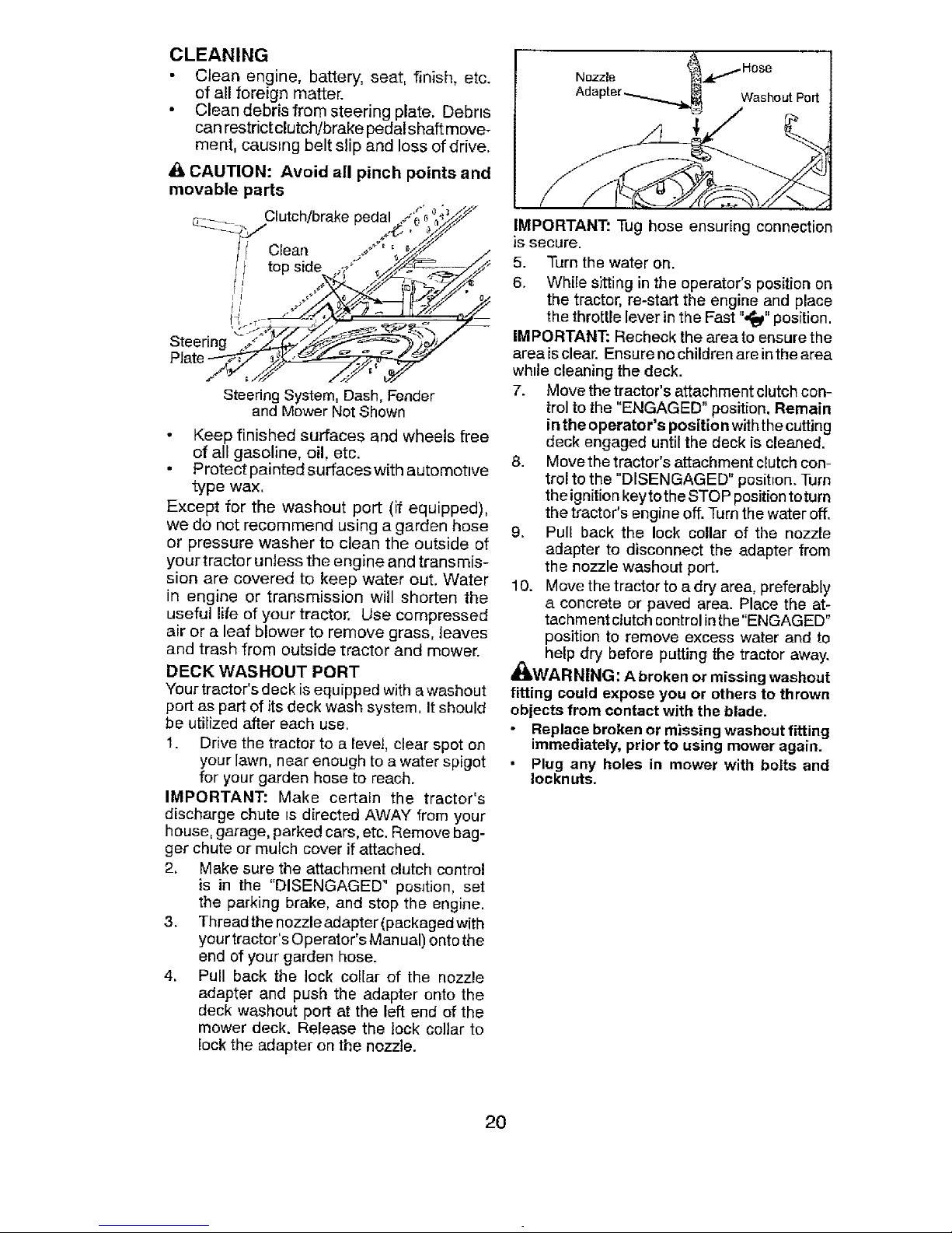
CLEANING
Clean engine, battery, seat, finish, etc.
of all foreign matter.
• Clean debris from steering plate. Debris
can restrict clutch!brake pedal shaft move-
ment, causing belt slip and loss of drive.
CAUTION: Avoid all pinch points and
movable parts
"7--_ Clutch/brake ./" '_.'_×_.r
, pedal .,_.e__'_._Y
It Clean ./' '_4_ t
Steeri.n-
Plate__
Steering System, Dash, Fender
and Mower Not Shown
Keep finished surfaces and wheels free
of all gasoline, oil, etc.
Protect painted surfaces with automotive
type wax.
Except for the washout port (if equipped),
we do not recommend using a garden hose
or pressure washer to clean the outside of
your tractor unless the engine and transmis-
sion are covered to keep water out. Water
in engine or transmission will shorten the
useful life of your tractor. Use compressed
air or a leaf blower to remove grass, leaves
and trash from outside tractor and mower.
DECK WASHOUT PORT
Your tractor's deck is equipped with a washout
port as part of its deck wash system. It should
be utilized after each use.
1. Drive the tractor to a level, clear spot on
your lawn, near enough to a water spigot
for your garden hose to reach.
IMPORTANT: Make certain the tractor's
discharge chute is directed AWAY from your
house, garage, parked cars, etc. Remove bag-
ger chute or mulch cover if attached.
2. Make sure the attachment clutch control
is in the "DISENGAGED" position, set
the parking brake, and stop the engine.
3. Thread the nozzle adapter (packaged with
your tractor's Operator's Man ual) onto the
end of your garden hose.
4. Pull back the lock collar of the nozzle
adapter and push the adapter onto the
deck washout port at the left end of the
mower deck. Release the lock collar to
lock the adapter on the nozzle.
IMPORTANT: Tug hose ensuring connection
]s secure.
5. Turn the water on.
6. While sitting in the operator's position on
the tractor, re-start the engine and place
the throttle lever in the Fast ",_" position.
IMPORTANT: Recheck the area to ensure the
area isclear. Ensure no children are in the area
while cleaning the deck.
7. Move the tractor's attachment clutch con-
trol to the "ENGAGED" position. Remain
in the operator's positio n with the cutting
deck engaged until the deck is cleaned.
8. Move the tractor's attachment clutch con-
trol to the "DISENGAGED" position. Turn
the ignition keyto the STOP position toturn
the tractor's engine off. Turn the water off.
9. Pull back the lock collar of the nozzle
adapter to disconnect the adapter from
the nozzle washout port.
10. Move the tractor to a dry area, preferably
a concrete or paved area. Place the at-
tachment clutch control in the "ENGAGED"
position to remove excess water and to
help dry before putting the tractor away.
_WARNING: A broken or missing washout
fitting could expose you or others to thrown
objects from contact with the blade.
Replace broken or missing washout fitting
immediately, prior to using mower again.
Plug any holes in mower with bolts and
Iocknuts.
2O
Page 21
WARNING: TO AVOID SERIOUS INJURY, BEFORE PERFORMING ANY
SERVICE OR ADJUSTMENTS:
t. Depress brake pedal fully and set parking brake.
2. Place attachment clutch in"DISENGAGED" position.
3. Turn ignition key to "STOP" and remove key.
4. Make sure the blades and all moving parts have completely stopped.
5. Disconnect spark plugwire from spark plug and place wire where it cannot
come in contact with plug.
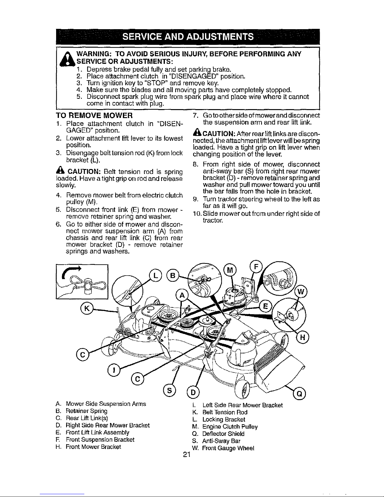
TO REMOVE MOWER
1. Place attachment clutch in "DISEN-
GAGED" position.
2. Lower attachment lift lever to its lowest
position.
3. Disengage betttension rod (K) from lock
bracket (L).
CAUTION: Belt tension rod is spring
loaded. Have a tight grip on rod and release
slowly.
4. Remove mower belt from electric clutch
pulley (M),
5, Disconnect front link (E) from mower -
remove retainer spring and washer.
6. Go to either side of mower and discon-
nect mower suspension arm (A) from
chassis and rear lift link (C) from rear
mower bracket (D) - remove retainer
springs and washers.
7. Go to other side of mower and disconnect
the suspension arm and rear lift link.
_, CAUTION: After rear lift links are discon-
nected, the attachment lift lever will be spring
loaded. Have a tight grip on lift lever when
changing position of the lever.
8. From right side of mower, disconnect
anti-sway bar (S) from right rear mower
bracket (D) - remove retainer spring and
washer and pull mower toward you until
the bar falls from the hole in bracket.
9. Turn tractor steering wheel to the left as
far as it will go.
10. Slide mower out from under right side of
tractor.
A. Mower Side Suspension Arms
B. Retainer Spring
C. Rear Lift Link[s)
D. Right Side Rear Mower Bracket
E. Front Lift Unk Assembly
E Front Suspension Bracket
H. Front Mower Bracket
Left S_de Rear Mower Bracket
K. Belt Tension Rod
L. Locking Bracket
M. Engine Clutch Pulley
Q. Deflector Shield
S. Anti-Sway Bar
W. Front Gauge Wheel
21
Page 22

TO INSTALL MOWER
1. SET PARKING BRAKE LEVER AND
LOWER ATTACHMENT LIFT LEVER
• Depress clutch/brake pedal all the way
down and hold.
Pull parking brake lever up and hold,
release pressure from clutch/brake
pedal, then release parking brake lever.
Pedal should remain in brake posttion.
Ensure parking brake will hold tractor
secure.
Brake
A_,CAUTION: Ltft lever is spring loaded.
Have a tight grip on lift lever, lower it slowly
and engage in lowest position. Lift lever is
located on left side of fender.
Li_
Lever
2. ASSEMBLE FRONT GAUGE WHEEL
(W) TO FRONT OF MOWER
H. Front Mower Bracket
W Front Gauge Wheel
X Shoulder Bolt
Y. 1-1/40.D. Washer
Z. 3/8-16 Locknut
3, TURN STEERING WHEEL LEFT AND
POSITION MOWER
• Turn steering wheel to the left as far as it
will go and position mower on right side of
tractorwith deflector shield (Q) tothe right.
Front
_Engine ?
_ Transaxle
Q. Deflector Shield
4. SLIDE MOWER UNDER TRACTOR
Bring belt forward and check belt for pro-
per routing in alf mower pulley grooves.
NOTE: Be sure mower side suspension
arms (A) are pointing forward before sliding
mower under tractor.
Slide mower under tractor until it is
centered under tractor.
A. Mower Stde Sus _ension Arms
Q. Deflector Shield
i
22
Page 23

5. INSTALL ANTI-SWAY BAR (S) +
(IF EQUIPPED)
_AY BAR (S) 1
Towards Towards "_b,_l
nsaxle Mower Deck _'-I
%
90° End Integrated Washer End
From right side of mower, first insert
90° end of anti-sway bar (S) into hole in
transaxle bracket ('t"), located near left _ D__wer Bracket
rear tire in front of transaxle. [' S. Anti-Sway Bar I
T. Transaxie
NOTE: Flashlight may be helpful. I . Bracket , I
6. ATTACH MOWER SIDE SUSPENSION
Anti-Sway : '_ - "- .... ARMS (A) TO CHASSIS
" +_<'; ; "- • Positionfrontholeinsidesuspensionarm
Bar(S) _" - _ _ i - \ (A)overpinonoutsideoftractorchassis
...... '\_L_ 'i__"_-_"_,.. _ _', and secure with large washer and large
' -<-" _ retainer spring (B).
• Repeat on opposite side of tractor.
Transaxle Bracket _ _rtl
Located Between Rear Tires
J
A.
B.
D.
Mower Side Suspension Arms
Retainer Spdng
Right Side Rear Mower Bracket
NOTE: Depending on model, bracket (T) may
be different than shown but hole for anti-sway
bar will be in same position/location.
Ptvot the integrated washer end of anti-
sway bar (S) towards mower deck bracket
on right side of mower. Insert integrated
washer end of bar into hole in rear mower
bracket (D). Move mower as needed to
insert integrated washer end of bar into
rear mower bracket (D).
Secure with small washer and small
retainer spring as shown.
7. ATTACH REAR LIFT LINKS (C)
• Insert rod end of rear lift link (C) into hole
(U) in tractor lift shaft suspension arm
and pivot link down to mower.
• Lift rear corner ofmower and position slot
in link assembly over pin on rear mower
bracket (D) and secure with large washer
and large retainer spring.
• Repeat on opposite side of tractor.
23
Page 24

D. Mower Bracket
'U. Hole
8 ATTACH FRONT LINK (E)
• Turn steering wheel to position wheels
straight forward.
From front of tractor, insert red end of
front link (E) through front hole in tractor
front suspension bracket (F).
• Move to leftside of mower and and insert
large retainer spring (G) through hole in
front link (E) behtnd front suspension
bracket (F).
• Insert other end of link (E) into hole in
front mower bracket (H) and secure with
washer and small retainer spring (J).
NOTE: Requires deck itfting.
Front Link ; _ ": ' " -
Location ,," .__,___." ,_7_::....
9 INSTALL BELT ON ENGINE CLUTCH
PULLEY (M)
• Disengage belt tension rod (K) from
locking bracket (L).
Install belt onto engine clutch pulley (M).
M.Engine
Clutch Pulley
IMPORTANT: Check belt for proper routing
in all mower pulley grooves and under
mandrel covers.
• Engage bert tension rod (K) on locking
bracket (L).
_kGAUTION: Belt tension rod is spring
loaded. Have atight grip on rod and engage
slowly.
• Raise attachment lift lever to highest
position.
If necessary, adjust gauge wheels
before operating mower as shown inthe
Operation section of this manual.
MOWER DRIVE BELT INSTALLATION
Follow procedure described in "TO
REPLACE MOWER BLADE DRIVE BELT"
in this section of this manual.
\
E. Front Lift Link Assembly
E Front Suspension Bracket
G. Large Retainer Spring
H. Front Mower Bracket
J. Small Retainer Spring
M. Engine Clutch Pulley
/
24
Page 25

TO LEVEL MOWER
Ensure tires are properly inflated to the PSi
shown on tires. If tires are over or under
inflated, it may affect the appearance of your
lawn and lead you to think the mower is not
adjusted properly.
VISUAL SI DE-TOrSI DE ADJUSTMENT
1. With all tires properly inflated and if your
lawn appears unevenly cut, determine
which side of mower is cutting lower.
NOTE: As desired, you can raise the low
side of mower or lower the high side.
2. Go to side of mower you wish to adjust.
3. With a 3/4" or adjustable wrench, turn
lift link adjustment nut (A) to the [eft to
lower the mower, or, to the right to raise
the mower.
Turn nut Turn nut
right to [eft to
raise lower
mower mower
NOTE: Each full turn of adjustment nut will
change mower height about 3/16" (4,7 m m).
4. Test your adjustment by mowing some
uncut grass and visually checking the
appearance. Readjust, if necessary, until
you are satisfied with the results.
PRECISION SIDE-TO-SIDE ADJUSTMENT
1. With alltires properlyinflated, parktractor
on level ground or driveway.
AI_.CAUTION: Blades are sharp. Protect
your hands with gloves and!or wrap blade
with heavy cloth.
2. Raise mower to its highest position.
3. At both sides of mower, position blade
at side and measure distance "A" from
bottom edge of blade to ground. The dis-
tance should be the same on both sides.
4. If adjustment is necessary, see steps in
Visual Adjustment instructions above.
•
lA
25
5. Recheck measurements; adjust if neces-
sary until both sides are equal.
FRO NT-TO-BACK ADJU STMENT
IMPORTANT: Deck must be {eveI side-
to-side,
To obtain the best cutting results, the mower
blades should be adjusted so the front tip
[s 1/8to 1/2" (3,1 to 12,7 mm) (lower than
the rear tip when the mower is in its highest
position.
_CAUTION: Blades are sharp. Protect
your hands with gloves and/or wrap blade
with heavy cloth.
• Raise mower to highest position.
• Position any blade so the tip is pointing
straight forward. Measure distance "B" to
the ground at front and rear tip of blade.
• if front tip of blade is not 1/8 to 1/2" (3,1
to 12,7 mm) lower than the rear tip, go to
the front of tractor.
• With an 11/16" or adjustable wrench,
loosen jam nut "A" several turns to clear
adjustment nut "B".
• With a 3/4" or adjustable wrench, turn
front link adjustment nut"B" clockwise (_)
(tighten) to raise the front of mower, or,
counterclockwise (,_'_) (loosen) to lower
the front mower.
Tighten adjust Loosen adjust
nut "B" to nut "B" to
raise mower lower mower
Loosen jam nut "A" first
NOTE: Each full turnof adjustment nut will
change mower height about 1/8" (3,1 ram).
• Recheck measurements, adjust if neces-
sary until front tip of blade is 1/8 to 1f2"
(3,t to 12,7 mm) lower than the rear tip.
Hold adjustment nut in position with
wrench and tighten jam nut securely
against adjustment nut.
Page 26

TO REPLACE MOWER BLADE DRIVE
BELT
MOWER DRIVE BELT REMOVAL
1, Park tractor on a level surface, Engage
parking brake,
2. Lower attachment lift lever to its lowest
position,
3. Disengage belttension rod (K) from lock
bracket (L),
CAUTION: Belt tension rod is spring
loaded. Have a firm grip on rod and release
slowly.
4. Remove screws (P) from R.H. and L.H,
mandrel covers and remove covers (Q).
5. Remove anydirtorgrass clippingswhich
may have accumulated around mandrels
and entire upper deck surface.
6. Remove belt from electric clutch pulley
(M), both mandrel pulleys (R) and all tdler
pulleys (V).
MOWER DRIVE BELT INSTALLATION
I. Install be_t around both mandrel pulleys
(R) and around idler pulleys (V) as shown.
2, Install beltonto electric clutch pulley (M).
IMPORTANT: Check belt for proper routing
in all mower pulley grooves.
3, Reassemble R.H. and L,H, mandrel cov-
ers (Q), Securely ttghten all screws.
4, Engage be}t tension rod (K) on locking
bracket (L).
,i_ CAUTION: Belt tension rod is spring
loaded, Have a tight grip on rod and engage
slowly.
5. Raise attachment lift lever to highest
position.
TO REPLACE MOTION DRIVE BELT
Park the tractor on level surface. Engage
parking brake. For assistance, there is a
belt installation guide decal on bottom side
of left footrest.
BELT REMOVAL -
1. Remove mower (See "TO REMOVE
MOWER" in this section of manual).
NOTE: Observe entire motion drive belt
and position ot all belt guides and keepers.
2. Removebeltfromstattonaryidler(A) and
clutching idler (B).
3. Remove belt from centerspan idler (C).
6. Pull belt slack toward rear of tractor.
Carefully remove belt upwards from
transmission input pulley and over cool-
ing fan blades (13).
4. Remove belt downward from engtne
pulley (El.
5. Slide belt toward rear of tractor, off the
steering plate (F) and remove from tractor,
BELT INSTALLATION -
1. Instatl new belttrom tractor rear to front,
over the steering plate (F) and above
clutch brake pedal shaft (G).
2. Pull belt toward front of tractor and roll
belt onto engine pulley (El,
3. Pull belt toward rear of tractor. Carefully
work belt down around transmission
cooling fan and onto the input pulley (O).
Be sure belt is inside the belt keeper.
4. Install belt on centerspan idler (C).
5. Install belt through stationary idler (A)
and clutching idler (B),
6, Make sure belt is in all pulley grooves
and inside all belt guides and keepers.
7. Install mower {See "TO INSTALL MOW-
ER" in this section of manual).
26
Page 27

TO CHECK BRAKE
Iftractor requires more than five (5) feet (1,5
m) to stop at highest speed in highest gear
on a level, dry concrete or paved surface,
then brake must be serviced.
You may also check brake by:
t. Park tractor on a level, dry concrete or
paved surface, depress brake pedal all
the waydown and engage parking brake.
2. Disengage transmission by placing
freewheel control in "transmission dis-
engaged" position. Pullfreewheel control
out and into the slot and release so it is
held in the disengaged position.
The rear wheels must lock and skid when
you try to manually push the tractor forward.
If the rear wheels rotate, then the brake
needs to be serviced. Contact a Sears or
other qualified service center.
FRONT WHEEL TOE-IN!CAMBER
Your new tractor front wheel toe-in and
camber is set at the factory and is normal.
The front wheel toe-in and camber are not
adjustable. If damage has occurred to
affect the factory set front wheel toe-in or
camber, contact a Sears or other qualified
service center.
TO REMOVE WHEEL FOR REPAIRS
1. Block up axle securely.
2. Remove axle cover, retaining ring and
washers to allow wheel removal (rear
wheels have a square key- Do not lose).
3. Repair tire and reassemble.
NOTE: On rear wheels only: attgn grooves in
rear wheel hub and axle. Insert square key.
4. Replacewashersandsnapretainlngring
securely in axle groove.
5. Replace axle cover.
NOTE: To seal tire punctures and prevent
flat tires due to slow leaks, purchase and
use tire sealant fro mSears. Tire sealant also
prevents tire dry rot and corrosion.
nn0 s'i"
Axle Cover '_Square Key (Rear
Wheel Only)
TO START ENGINE WITH A WEAK BAT-
TERY
_kWARNING: Lead-acid batteries gener-
ate explosive gases. Keep sparks, flame
and smoking materials away #ore batteries.
Always wear eye protection when around
batteries.
If your battery is too weak to start the engine,
it should be recharged. (See "BATFERY" in
the MAINTENANCE section of this manual).
If "jumper cables" are used for emergency
starting, follow this procedure:
IMPORTANT: Your tractor is equipped with
a 12 volt system. The othervehic[e must also
be a 12 volt system. Do not use your tractor
battery to start other vehicles.
TO ATTACH JUMPER CABLES -
1. Con nect one end of the RED cable to the
POSITIVE (+) terminalof each battery(A-
B). taking care notto short againsttractor
chassis.
2. Connect one end of _the BLACK cable
to the NEGATIVE (-) terminal (C) of fully
charged battery.
3. Connect the other end of the BLACK
cable (D) to good chassis ground, away
from fuel tank and battery.
TO REMOVE CABLES, REVERSE ORDER
1. BLACK cable firstfrom chassis and then
from the fully charged battery.
2. RED cable last from both batteries.
Weak or Dead Fully Charged
Battery Battery
27
Page 28

REPLACING BATTERY
_jt, WARNING: Do not short battery termi-
nals by allowing a wrench or any other object
to contact both terminals at the same time.
Before connecting battery, remove metal
bracelets, wristwatch bands, rings, etc.
Positive terminal must be connected first to
prevent sparking from accidental grounding.
1. Lift hood to raised position.
2. Remove terminal cover.
3. Disconnect BLACK battery cable then
RED battery cable and carefully remove
battery from tractor.
4. Install new battery with terminals in same
position as old battery.
5. Reinstall terminal cover.
6. First connect RED battery cable to posi-
tive (+) battery terminal with bolt and nut
as shown. Tighten securely.
7. Connect BLACK grounding cable to
negative (-) batteryterminal with remarn-
ing bolt and nut. Tighten securely
8. Close hood.
na_/__, Negative
(8lack)
Cable
Term=
covo,
Pos,tive f_k _ "_" _--_,.z-_!-_
(Red)-'- _.. _l__
Cabie
TO REPLACE HEADLIGHT BULB
1. Raise hood.
2. Remove bulb holder from the hole in the
backside of the grill.
3. Replace bulb in holder and install bulb
holder securely back into the hole in the
backside of the grill.
4. Close hood.
INTERLOCKS AND RELAYS
Loose or damaged wiring may cause your
tractor to run poorly, stop running, or prevent
it from starting.
• Check wiring.
TO REPLACE FUSE
Replace with 30 amp automotive-type plug-
in fuse. The fuse holder is located behind
the dash.
TO REPLACE FUSE
Replace with 20 amp automotive-type plug-
in fuse. The fuse holder is located behind
the dash.
TO REMOVE HOOD & GRILL ASSEMBLY
1. Raise hood.
2. Unsnap headlight wire connector.
3. Remove retainer clip and washer from
right hand pivot pin.
4. Stand in front of tractor. Grasp hood at
sides and slide left removing hood from
pivot pins and lift hood off of tractor.
5. When replacing hood, reconnect the
headlight wire connector, and reinstall
the washer and retainer clip on the nght
hand pivot pin.
_t_Hood
Le PivotPio
_sher
_iner Clip
_ '_ _ "Right Pivot Pin
Headlight Wire Connector
ENGINE
TO ADJUST THROTTLE CONTROL
CABLE
The throttle control has been preset at
the factory and adjustment should not be
necessary Check adjustment as described
below before loosening cable. If adjustment
is necessary, see engine manual,
TO ADJUST CHOKE CONTROL
The choke control has been preset at the
factory and adjustment should not be neces-
sary. [f adjustment is necessary, see engine
manual.
28
Page 29

Immediately prepare yourtractor for storage
at the end of the season or if the tractor will
not be used for 30 days or more.
_WARNING: Never store the tractor with
gasoline in the tank inside a building where
_umes may reach an open flame or spark.
Allow the engine to cool before storing in
any enclosure.
TRACTOR
Remove mower from tractor for winter stor-
age. When mower is to be stored for a period
of time, clean it thoroughly, remove all dirt,
grease, leaves, etc. Store in a clean, dry area,
1. Clean entiretractor (See"CLEANING"in
the Maintenance section ofthis manual).
2. Inspect and replace belts, if necessary
(See belt replacement instructions in the
Service and Adjustments section of thts
manual).
3. Lubricate as shown in the Maintenance
section of this manual.
4, Ensure that all nuts, bolts and screws
are securely fastened. Inspect moving
parts for damage, breakage and wear.
Replace if necessary.
5. Touch up all rusted or chipped paint
surfaces; sand lightly before painting.
BATTERY
• Fully charge the battery for storage.
• After a period of time in storage, battery
may require recharging.
• To help prevent corrosion and power
leakage during tong periods of storage,
battery cables should be disconnected
and battery cleaned thoroughly (see "TO
CLEAN BATTERY AND TERMINALS" in
the Maintenance section of this manual).
• Aftercleaning, leave cables disconnected
and place cables where they cannot come
in contact with battery terminals.
• If battery is removed from tractor for
storage, do not store battery directly on
concrete or damp surfaces.
* If unit is equipped with battery indicator/
charging plug, an optional charging unit
may be purchased and connected to the
unit to charge the battery during long term
storage. Inspect and clean the battery
terminals as needed prior to long term
storage with charger connected.
ENGINE
FUEL SYSTEM
IMPORTANT: It is important to prevent
gum deposits from forming in essential fuel
system parts such as carburetor, fuel hose,
ortank during storage. Also, alcohol blended
fuels (called gasohol or using ethanol or
methanol) can attract moisture which leads
to separation and formation of acids during
storage. Actdic gas can damage the fuel
system of an engine while in storage.
* Empty the fuel tank by starting the engine
and letting it run until the fuel lines and
carburetor are empty.
• Never use engine or carburetor cleaner
products in the fuel tank or permanent
damage may occur.
• Use fresh fuel next season.
NOTE: Fuel stabilizer is an acceptable al-
ternattve in minimizing the formation of fuel
gum deposits during storage. Add stabilizer
to gasoline in fuel tank or storage container.
Always follow the mix ratio found on stabilizer
container. Run engine at least 10 minutes
after adding stabilizer to allowthe stabilizer to
reach the carburetor. Do not empty the gas
tank and carburetor if using fuel stabilizer.
ENGINE OIL
Drain oil (with engine warm) and replace
with clean engine oil. (See "ENGINE" in the
Maintenance section of this manual).
CYUNDER(S)
t, Remove spark plug(s).
2, Pour one ounce (29.5 mL) of oil through
spark plug hole(s) into cylinder(s).
3. Turn ignition key to "START" position for
a few seconds to distribute oil.
4. Replace with new spark plug(s).
OTHER
• Do not store gasoline from one season to
another.
• Rep]aceyour gasoline can ifyour can starts
to rust. Rust and/or dirt in your gasoline
will cause problems.
, If possible, store your tractor indoors and
coveritto give protectionfrom dust and dirt.
• Cover your tractor with a suitable protec-
tive cover that does not retain moisture.
Do not use plastic. Plastic cannot breathe
which allows condensation to form and will
cause your tractor to rust.
IMPORTANT: Never cover tractor while
engine and exhaust areas are still warm.
29
Page 30

TROUBLESHOOTING CHART:
See appropriate section in manual unless directed to Sears service center
PROBLEM ......CAUSE
Will not start I Out of fuel.
2 Engine not "CHOKED" properly.
3 Engine flooded.
Hard to start
Engine will not
turn over
4 Bad spark plug
5 Dirty air filter.
6 Dirty fuel Nter.
7 Water in fuel.
8 Loose or damaged wiring
9 Engine valves out of adjustment.
1 D=rty air filter.
2 Bad spark plug.
3 Weak or dead battery.
4 Dirty fuel filter.
5 Stale or dirty fuel
6 Loose or damaged wiring.
7 Engine valves out of adjustment.
1 Clutch/brake pedal not depressed
2 Attachment clutch is engaged.
3 Weak or dead battery_
4 Blown fuse.
5 Corroded battery termtnals.
6 Loose or damaged w_nng,
7 Fau[ty ignition switch,
8 Faulty solenoid or starter,
9 Faulty operator presence
swltch(es).
CORRECTION
1 Fill fuel tank.
2 See "TO START ENGINE" m
Operation section.
3 Watt several minutes before
attempting to start.
4 Replace spark plug.
5 Clean/replace air filter.
6 Replace fuel filter.
7 Empty fueltank and carburetor,
refill tank with fresh gasoline and
replace fuel filter.
8 Check all wiring.
9 Contact a Sears or other qualified
service center.
1 Clean/replace air filter.
2 Replace spark plug.
3, Recharge or replace battery.
4 Replace fuelffiter.
5 Empty fuel tank and refill tank wtt_
fresh, clean gasoline.
6 Check all wtnng
7 Contact a Sears or other qualified
service center.
1 Depress clutch/brake pedal.
2 Disengage attachment cfutch.
3 Recharge or replace battery.
4 Replace fuse.
5 Clean battery terminals.
6 Check allwlrlng.
7 Check/replace ignition switch.
8 Check!replace solenoid or starter.
9 Contact a Sears or other qualified
service center.
3O
Page 31

TROUBLESHOOTING CHART:
See appropriate section in manual unless directed to Sears service center
PROBLEM CAUSE
Engine clicks but 1 Weak or dead battery. 1
will not start
2 Corroded battery terminals. 2
3 Loose or damaged wtring. 3
4 Fauity solenoid or starter. 4
Loss of power 1 Cutting too much grass/too fast. 1
2 Throttle m "CHOKE" posttton. 2
3 Build-up of grass, leaves and 3
trash under mower.
4 Dirty air filter.
5 Low oil level/dtrty oil.
6 Faulty spark plug.
7 Dirty fuel filter.
8 Stale or dirty fuel.
Excessive vibration
Engine continues to
run when operator
leaves seat with
attachment clutch
engaged
4
S
6
7
6
9 Water in fuel.
10 ! Spark plug wire loose. 10
11 Dirty engine atr screen/fins. 11
12 Dirty/clogged muffler. 12
13 Loose or damaged wrong. 13
14 Engine valves out of adjustment. 14
t Worn, bent or loose blade. 1
2 Bent blade mandrel. 2
3 Loose/damaged part(s). 3
I Faulty operator-safety presence 1
control system.
CORRECTION
Recharge or replace battery.
Clean battery terminals.
Check all wiring,
Check/replace solenoid or starter.
Raise cutting height/reduce
speed.
Adjust throttle control.
Clean understde of mower
housmg,
Clean/replace air filter.
Check otl level/change etl.
Clean and regap or change spark
plug.
Replace fuel filter.
Empty fuel tank and refill tank with
fresh, clean gasoline.
Empty fuel tank and carburetor,
refill tank with fresh gasoline and
replace fuel filter.
Connect and tighten spark plug
wire.
Clean engine air screani{ins.
i Clean!replace muffler.
Check all wirin 9.
Contact a Sears or other qualified
service center.
Replace blade. Tighten blade bolt.
Contact a Sears or other
qualified service center.
Tighten loose part(s).
Replace damaged parts.
Check wiring, switches and
connections. If not corrected,
i contact a Sears or other qualified
service center.
_ CAUT|ON: DO NOT
operate machine until
problem Is corrected.
31
Page 32

TROUBLESHOOTING CHART:
See appropriate section in manual unless directed to Sears service center
PROBLEM
Poor cut - uneven
cutting
Mower blades will
not rotate
Poor grass
discharge
Headlight(s) not
Iworking
i(if so equipped)
iBattery will not
charge
CAUSE CORRECTION
1 Worn, bent or lOOseblade. 1 Replace blade. Tighten blade bolt
2 Mower deck not level. 2 Level mower deck.
3 Buildup of grass, leaves, and 3 Clean underside of mower
trash under mower, housing.
4 Bent blade mandrct. 4 Contact a Scars or other
qualified service center.
5 Clogged mower deck vent from 5 Clean around mandrels to
build-up of grass, leaves, and open vent holes.
trash around mandrels.
1 Obstruction _nclutch mechanism. 1 Remove obstruction.
2 2 Replace mower drive belt.
3 3 Replace idler pulley.
4 4 Contact a Sears or other
qualified service center.
1 Place throttEe control in "FAST"
position.
2 Shift to slower speed.
3 Allow grass to dry before mowing
4 Level mower deck.
5 Check tires for proper PSI.
6 Replace!sharpen blade. Tighten
blade bolt.
7 Clean unders=de of mower
housing.
8 Replace mowerdrlve belt.
',9 Reinstall blades sharp edge down
10 Replace with blades listed in
this manual.
11 Clean around mandrels 1o
open vent holes.
Worn/damaged mower drive belt
Frozen idler pulley.
Frozen blade mandrel.
1 Engine speed too slow
2 Travel speed too fast_
3 Wet grass.
4 Mower deck not level.
5 Low/uneven tire a_r pressure,
6 Worn, bent or loose blade.
7 Buildup of grass, leaves and
trash under mower.
8 Mower drive belt worn
9 Blades improperly installed.
10 improper blades used.
11 Clogged mower deck vent holes
from buildup of grass, leaves, and
trash around mandrels.
1 Ltght sw_tch is "OFF".
2 Bulb(s) or lamp(s) burned out.
3 Faulty light switch.
4 Loose or damaged wiring_
5 Blown fuse.
1 Bad battery cell(s).
2 Poor cable connecttons.
3 Faulty regulator (if so equipped).
4 Faulty alternator.
1 ! Turn light switch "ON".
2 i Replace bulb(s) or lamp(s}.
3 Check/replace hght switch.
4 Check wiring and connections.
5 Replace fuse.
1 Replace battery.
2 Check/clean all connections.
3 Replace regulator.
4 Replace alternator.
32
Page 33

TROUBLESHOOTING CHART:
See appropriate section in manual unless directed to Sears service center
PROBLEM
Loss of drive
t
2
Engine "backfires"
when turning
engine "OFF"
Engine dies when
tractor is shifted
into reverse
CAUSE
Freewheel control in
"DISENGAGED" position.
Debris on steedng plate (if
equipped).
3 Motion drive belt worn, damaged, 3
or broken,
4 iAxle key missing,
,,,,,,,,,,, ........
1 Engine throttle control not eel 1"
between half and full speed (fast)
position before stopping engine,
CORRECTION
Place freewheel control in
"ENGAGED" position.
See "CLEANING" in the
maintenance section.
i Replace motion drive belt,
Install axle key at rear wheel. See
"TO REMOVE WHEEL" in the
Service and Adjustments section.
Move throt'de control between
half and full speed (fast) position
before stopping engine,
Reverse operation system ('ROS)
is not "ON" while mower or other
attachment is engaged,
1 Tu,nig"itio,key,oROS"ON"'.............
position. See Operation section,
NEED HORE HELP?
Youq_ find the answe_ and more on managemyhome.com - for free!
• Findthis and all your other product manuals online,
• Get answersfrom our team of home experts.
- Get a personalized maintenance plan for your home.
, Find information and tools to help with home projects.
manage home
brought to you by Seats
33
Page 34

SUGGESTED GUIDE FOR SIGHTING SLOPES FOR SAFE OPERATION
ONLY RIDE UP AND DOWN HILL,
NOT ACROSS HILL
15 DEGREES MAX.
_jh= ARNING: To avoid serious injury, operate your tractor up and
down the face of slopes, never across the face. Do not mow
slopes greater than 15 degrees. Make turns gradually to prevent
tipping or loss of control. Exercise extreme caution when
changing direction on slopes.
1. Fold this page along dotted line indicated above.
2. Hold page before you so that its left edge is verUcatly parallel to a tree
trunk or other"upright structure.
3. Sight across the fold in the direcUon of hill slope you want to measure.
4. Compare the angle of the fold with the slo_0e of the hill.
Page 35

Garantia .......................................................... 35
Reg]as de Segundad ...................................... 36
Espec]ficaciones del Producto ........................ 39
Montaje/Pre Operaci6n ................................... 40
OperaciSn ...................................................... 42
Mantenimiento ............................................... 50
Programa de Mantenimiento .......................... 50
Servicio y Ajustes ........................................... 54
A[macenamiento ............................................. 63
ldentificaci6n de Problemas ........................... 64
Servicio Sears ............................. Contraportada
GARANTiA LIMITADA DE CRAFTSMAN
DURANTEDOSA_JOS a part=r de la fecha de compra, redes los piezas no funglbles de este equipo est&n
garant_zadas centre defectos en los materia[es o la mane de obra. Con eTcomprobante de compra, una pieza no
f_ngible con defectos se reparar& o cambia[& de forma gratuita a opci6n del vendecior.
Garantia limitada de la bateria
DU RANTE 90 DiAS a partlr de la [echo de corepro, la bateria (una pteza fungible) de este equipo est& garantizada
contra defectos en los matenales o la mane de obra. Con el comprobaote de compra, usted rec=bira ureabater{a
nueva, s=ncargo. Usted es responsable del coste de la mane de obra de instalaci6n de la bateria.
Otras garantlas limltadas
En tas siguientes garantias adleLona[es, usted es responsable del costa de la mane de obra de tnstafaciSade la
pleza despu_s del segundo a_o de lafecha de compra
DURANTE CINCO Ak;OS a partir de ta fecha de compra, el bastidor de este equlpo est& garantlzado conLra
cualquier defecto en los materiales o[a mane de obra. Con el cemprobante de compra, usted reciblr& un nuevo
bastidor, sm cargo.
DURANTE DIEZ A£OS a partir de la fecha de compra, a[ eje delantero de este equipo eat& garantizado centre
cualqu,er defecto en los mater=ares o en la mane de obra. Con et comprobante de compra, usted recib=r&un nuevo
eje sin nmg_n costo.
SIEMPRfE QUE SEA USADO per el propietano or[g=naldespa6s del d_cimo aSo a partir de Eafecha de compra,
el hterro fund=do del eje delantero (s=Io ttene) de este equipo est& garantizado centre cualquter defecto en los
materiales o la mane de ob[a. Con el comprobante de compra, usted recibtr&un nuavo hierro fundido del eje
delantere de forma gratuita.
SERVICIO DE GARANTLA
Papa obtenor detalles de la cobertura de la garant_asobre reparaciones o sustituciones gratuitas, visita la p&gina
web: www craftsman.comiwarranty
Sustituci6n del producto
Si no se puede reparar o sustitutrel pteza, usted rec=blr& un nuevo equipo dei mismo modelo o equivalente.
Restricci6n de garantia
Esta garantia ser& nula si este producto se utll=za alguna vez pare brindar aervicies comerciales o 81se a[quila a
otra persona.
Esta garantia cubre tJNICAMENTE _lefectos de materialy mane de obra. La ¢obertura de garantia NO incluye:
• Gomponentes fungtbIes (excepto la bateria) qua se puedan desgastar per el use normal dentro de[ per{odo de
garantia, incluso (pare sm hmitarse a eflo) hojas, buj[as, correas yfiltms de ace=to,alre y gasohna.
• Servicles de mantenimiente eat&odor,cambios de aceite o afinaciones.
• Reemplazo o reparac[6n de neumaticos per pinchazos causados per oblates externos come cloves, espinas,
tocones o vldrios.
• Reemplazo o reparaci6n de neum&tlcos o [uedas per desgaste normal, accidentes o per operaci6n o
mantenlmlento incorrectos.
• Reparacioaes necesartas per abuse del operador, incluso (pero aia Ilmitarse a ello) daSos causades per
remoIcar objetos qua superen la capacidad del equipo tractor, chocar centre objetos qua doblen el bastinor, el
conlunto del eje o el cig_eSal e sebrepasar la volocidad de! motor.
• Reparac=ones necesarias per neghgencia del operader, inoluso (pare sin [immerse a ello) doses e[6ctrieos y
mecAnices causados per el almacenamiento incorrecto, per no usar el grade y la cantidad correctes de aceite de
motor, per no mantener del muella libra de residues inflamables o per no mantener el equ=petractor do acuerdo
can los instrucclones qua contiene el manual dGIoperador.
• Limp=eza o reparaclones del motor (sisterna de combusttbla) cuande se determine qua se us6 combuStible
contaminado y ox=dado (sarfo). En general, el combusttble debe usarse dentro de los 30 dies postedores a su
compra.
• Detenoro y desgaste normaT de los acabados exteriores o sust_tuci6n de r_tulos de productos.
Esta garant_a le otorga derechos legales especif_cos, y osted tambi_n puede tenor otros derechos que varian de
on estado a otro.
Sears Brands Management Corporation, Hoffman Estates, IL 50179
35
Page 36

_,PELIGRO: Esta Maquina cortadora es capaz de amputar las manosy los pies y de lanzar
objetos, si no se observan las instrucciones de seguridad siguientes se pueden producir
lesiones graves o la muerte.
ADVERTENCIA: Siempre desconecte el alam-
bre de la bujia y p6ngalo donde no pueda entrar
en contacto con la bujia, para evit_r el arranque
per accidente, durante la preparaci6n, el trans*
porte, el ajuste o cuando se hacen reparaciones.
,_ ADVERTENOIA: No avance cuestaabajo a pun-
to muerto ya que podria perder elcon_ol dee tractor.
_,ADVERTENCIA: Remolque solamente los
accesorios recomendados y conformes a las
caracterlsticas ind=cadas per el fabricante de su
tractor. Tenga cuidado y prudencia al utilizar el
tractor. Cuando se encuentre en un declive, oper
utillzando exclusivamente la velocidad m&s baja.
En case de un declive una carga excesiva po-
dria resultar pehgrosa. Los neumatlcos pueden
perder la tracci6n con el suelo y hacerle perder
el control de su tractor.
ADVERTENCIA: El tube de escape del motor,
algonos de sos constituyentes y algunos com-
ponentes del vehioulo oontienen o desprenden
productos quimicos conocidos en el Estado de
Cahfornia come causa de c&ncer y defectos al
nacimiento u otros dafios reproducbvos.
_kADVERTENCIA: Los berries, terminales
y accesorios relatives de la bateria conbenen
plomo o compuestos de plomo, productos quimi-
cos conocidos en el Estado de California come
causa de c&ncer y defectos al nacimiento u otros
dafios reproduct_vos. Lavar las rnanos despu_s
de man|pularlos.
I. NINES
_bADVERTENCIA: LOS NfI_IOS PUEDEN
SUFRIR DANES CON EL use DE ESTE EQUI-
PO. La Academia Estadounidense de Pediatria
(American Academy of Pediatncs) recomienda
que s61e se permita a nir_os con una edad mlni-
ma de 12 aSos manejar m_quinas cortac@sped
manuales, y at menos de 16 aries para manejar
tractores cortac@sped.
,_ ADVERTENClA: LOS NIL'_OS PUEDEN SU-
FRtR HERIDAS GRAVES O MUERTE A CAUSA
DE ESTE EQUIPO Lea y slga atentamente tedas
las instrucclones sigulentes
S_ el operador no pone atenci6n a la presencia
de los nl]5os pueden ocurdr accidentes tr&gicos.
Los niEos a menudo estAn atraidos per la m_.qui-
na y Eas actividad de cortar. No dar per hecho
de que los nifios se queden adonde estaban la
6ltima vez que los vistes.
* Mantener los nifios fuera del _rea de corte y
vigifados per un adulto responsable uegg.#...g.O.
sea el operador.
- Estar alerta y apagar la m_.quina s[ un niSos
entra en el &rea.
- Antes y durante fa marcha atr,'_s, mirar adelante
y abaje para ver si hay nil_os pequeSos.
- Nuncallevar nlSos, incluso si haylascuchillas
apagadas Podrian caer y herirse seriamente
o interfenr con ei func_onamiento seguro de la
m_quina, los nifios que se han tlevado prec-
edentemente pueden aparecer de pronto en el
&rea de corte per otro paseo y ser atropellados
o tumbados per la m_.qu=na.
• Nunca dejar que los nifios man_pulen la
m&qulna.
• Tener el m&ximo cu=dado cuando se acerca
a cantos ciegos, arbustos, grboles u otros
objetos que pueden impedir la vista de nifios.
|1, FUNCIONAMIENTO GENERAL
• Leer, entender y seguir todas las instrucciones
sobre ta m_.quina yen el manual antes de
empezar.
• No poner las manes o los pies cerca de partes
giratorias o debajo de ]a m__quina. Mantener
slempre lirnpla la abertura de descarga
• Permltir el funcionamiento de la m&quina s61o
a adultos que tengan familiaridad con las
instrucclones.
• Limplar el a_rea de objetos come piedras,
juguetes, cables, etc. que pueden ser reeogi-
des y disparados con las cuchillas.
• Asegurarse de que el &rea est6 fibre de otras
personas antes de poneda en marcha. Parar
Ia m&qulna si algulen entra en el _.rea
• Nunca Ilevar pasajeros.
• No cortar marcha atr&s al no set absolu-
tamente necesario. Mirar s_empre abajo y
delante mientras se precede atr&s.
• Nunca dirigir el matenal descargado hac=a na-
die. Ewtar descargar material contra paredes
u obstrucciones. El material podria rebotar
hacia el operador. Parar las cuchillas cuando
se pasan superficies de grava.
• No maneje la m&quina s_ no t=ene la trampa
para c_sped completa, la canaleta de descarga
u otros d=spos=tivos de segundad en su lugar
yen func=onamiento.
• Ralentizar antes de girar.
36
Page 37

• Nunca dejar una m&quina encendida sin vigi-
lancia. Apagar siempre las cuchillas, poner et
freno de estacionamiento, parar el motor, y
quitar las Ilaves antes de bajar.
• Desenganche las hojas cuando no est6
cortando c6sped. Apague el motor y espere
hasta que todas las partes se detengan por
completo antes de limpiar la m&quina, retirar
la trampa para c6sped o destapar la canaleta
de descarga.
• Hacer funcionar la m&quina s61o con Laluz del
dia o luz artificial buena.
• No hacer funcionar la m&quina estando bajo
los efectos de alcoho[ o droga.
• Porter atenci6n al tr&flco cuando se opera
cerca de calles o se cruzan.
• Poner la m&xima atenci6n al cargar o descar-
gar la m&quina en una caravana o carm6n.
• Uevar s_empre galas de protecci6n cuando se
hace funcnonar la m&quina.
• Use protectores de oidos para evitar daSos en
la audici6n.
• Los datos inducan que los operadores a partir
de los 60 a5os est_.n afectados por un gran
porcentaje de heridas relativas a la conducci6n
del cortac_sped. Estos operadores tendrian
que evaluar su habilidad de hacer funcionar
el cortac@sped de modo Io bastante seguro
para proteger a si mismos y a otras personas
de heridas graves.
• Segu_r las recomendaciones del fabricante
para los pesos y contrapesos de las ruedas.
• Mantener la m&quina libre de hierba, hojas
u otros escombros que pueden tocar el
tubo de escape / partes del motor cal_entes
y quemarse. No permitir queet puente del
cortac@sped cargue hojas u otros residuos
que pueden causar acumulaciones. Limpiar
toda salp_cadura de aceite o carburante antes
de hacer operaciones sobre la m&quina o
guardarla. Dejarla enfriar antes de guardarla.
Iii. FUNCIONAMIENTO EN PENDIENTES
Las penduentes son el mayor factor de acciden-
tes relativos a la p_rdida de control y vuelco,
que pueden causar severas heridas o muerte.
El func_onamiento en pend_entes requiere una
atenci6n extra. Si no es posnble haeer marcha
atr_s on una pendiente o site sientes incomodo,
no la cortes.
,_ ADVERTENOIA: A1 eargar o descargar la
m&quina, no sobrepase el &ngulo m&ximo reco-
mendado de 15°
• Cortar hacia arr=bay abajo de una pendiente,
no de modo horizontal.
• Porter atenciones a los hoyos, [as raioes, los
bultos, las piedras u otros objetos escondidos,
El terreno irregular puede volcar la m_quina.
La hierba afta puede esconder obst&calos.
• Escoger una velocidad de marcha baja de
mode que no sea necesario pararse ocambiar
estando en una pendiente.
• No cortar la hierba mojada, f_s ruedas pueden
pettier tracci6n. Porter siempre una rnarcha
cuando se est& en pendientes.
• No poner en punto muerto e ir cuesta abajo.
• Evitararrancar, pararse o girar on una pendien-
te. Si las ruedas pierden tracci6n, desconectar
las cuchillas y proceder despacio cuesta abajo
en la pendiente.
• Mantener todo los movimientos en las pen-
dientes lentos y gradual. No hacer cambios
repentinosde velocLdad o direcci6n, ya que
pueden causar el escape de la m_.quina.
• Porter la rm_ximaatenci6n cuando la m_.quina
funciona con captadores de hierba u otros
dispositivos enganchados; pueden afectar la
estabilidad de la rn&quina. No usar en pendi-
entes empinados.
• No intentar estabilizar la m&quina poniendo el
pie en el terreno.
• No cortar cerca de bajadas, cunetas yodLlas.
Las m&quina puede volcarse improvisamente
si una rueda est& en el borde o se hunde.
• Si la m&quina se para mientras va cuesta
arriba, desconectar las cuchillas, porter la
marcha atr&s y ir hacia atr&s despacio.
- No girar estando en pendientes si no es nece-
sario, y luego girar despacio y gradualmente
cuesta abajo, si es posible,
IV. REMOLQUE
• RemolcarsSlo conuna m&quina que tengaun
gancho diser_ado para remolcar. Enganehar el
equipo o remolcar s61oen el punto dispuesto
al efecto.
• Seguir las recomendaciones del productorcon
respectoa los limites del equipo por remolcar
y el remolque on pendientes.
• Nunca permit=r que nitros u otras personas
est@ndentro del equipo pot remolear.
• En pendientes, el peso del equipo remolcado
puede causar la p6rdida de tracci6n y ]a p6r-
dida de control.
• Viajar despacio y dejar mrs distancia para
frenar.
37
Page 38

V. SERViClO
MANIPULACION SEGURA DE LA GASOLINA
Para evitar heridas personales o dar_os alas
cosas, poner el m&x=mo cuidado a la hera de
manipular [a gasolina. La gasolina es extrema-
mente inflamable y los vapores son explosives,
• Apagar todos Los cigarrillos, cgarros, pipas y
otras fuentes de ignlcl6n.
• Usar s61o contenedores para gasotina aproba-
dos.
• Nunca quitar el tap6n de ta gasolina o aSadir
carburante con el motor en rnarcha.
• dejar enfriar el motor antes del abastecimiento
de la gasolina.
• Nunca abastecer la m&quina at interior de un
local.
• Nunca guardar la m_.quina o el contenedor
del carburante donde haya una llama abierta,
chlspas o una luz piloto come un caientador
de agua u otros dispositivos.
• Nunca llenar los contenedores al interior de
un vehioulo o en una caravana o cami6n
recubiertos con un forte de pl&stico. Colocar
siempre [os contenedores en el terreno lejos
del vehiculo cuando se est& llenando.
• Qu=tar el equipo de gas del camndn o caravana
y abastecerio en el terreno. S_ no es pos=ble,
abastecer dicho equipo con un contenedor por-
t__tiL,m&s bien que de un surtidor de gasoJina.
- Mantener la boquilla a contacto del borde
del dep6s_to de carburante o la abenura del
contenedor durante toda la operac_6n de
abastecimiento, No utilizar un disposnt=vo con
boquilla cerrada-ab=erta.
• Si se vierte earburante sobre la ropa, cambi-
arse la ropa inmediatamente.
• Nunca Ilenar el dep6sito m__s de Io debido.
Volver a colocar e[ tap6n del gas y cerrar de
mode firme.
OPERACIONES DE SERVICIO GENERALES
• Nunca hacer funcionar la m&quina en un &tea
cerrada.
• Mantener todas las tuercas y pernos apretados
para asegurarse de que trabaja en condieiones
seguras.
• Nunca manipute los dispositivos de seguri-
dad. Nunca mterfiera con la operaci6n de un
dispositivo de seguridad o reducir la proteco
ci6n proporcionada per un dispositivo de
seguridad. Vedfique el func=onamiento correcto
con regularidad. NUNCA utihce una m_qu=na
con un disposdwo de seguridad que no est&
funcionando correctamente
• Mantener la m_.quina libre de hierba, hojas
u otros residues acumulados. Limpiar las
salpicaduras de aceite o carburante y quitar
cualquier cosa mojada con carburante. Dejar
que la m_.quina se enfrle antes de guardarla.
• Si se golpea un objeto ajeno, hay que pararse
e inspeceionar la m&quina. Reparar, si es
necosario, antes de velvet a poner en marcha.
• Nunca hacer ning_n ajuste o reparaci6n con
el motor en funcion.
• Verifique los componentes de la trampa para
cesped y la canaleta de descarga con freeuen-
eia y sushtuya con repuestes recomendados
per el fabncante cuando sea necesario.
• Las cuchillas de[ cortac@sped son aflladas.
Envolver ta cuchil[a, ponerse guantes y poner
la m__xlma atenci6n cuando se hacen opera-
clones en elias.
• Controlar el funcionamiento del freno frecuent-
emente. Ajustar y hacer las operaciones de
mantenimiento cuando eso sea necesano.
• Mantener y sustituir las etiquetas de seguridad
e instrucci6n, cuando sea necesarlo.
®
Use protectores de oidos para evitar daSos en la
audici6n.
Llevar siempre gafas de protecci6n cuando se hace
funcionar la m_quina.
38
Page 39

ESPECIFICACIONES DEL PRODUCTO
Capacidad yTipo 3.0 Galonesi11_35 L
de Gaso[ina' Regular Sin P!omo*
Tape de Aceite SAE 30 (sobre 32°F/0°C)
APE SG-SL): SAE 5W30 (deabajo 32° F]0°C)
Capacidad de Con Fi]tro' 64 Oz./1,89 L
Aceite: Sin F[Itm: 60 0z./1,77 L
Bujia Champion RC12YC
(Gap..030"/0.76 mm}
Sislema de 16 Amps @ 3600 RPM
Carga:
Bater[a' AmpiHr: 28
Min. CCA: 230
Mndelo TamaSo U1R
Torsi6n del Perno 45-55 Ft. Lbs./62-75 Nm
ida la Cuchilla:
A
_,j._. Esta m&quina puede utilizar gasolina con un con-
tenido de hasla el 10% de etanol {El 0). El use de
una gasolina qua supere e! 10% de etanol (Et0)
anular& la garantla olel producto.
FELICITACIONES per la compra de su tractor, Ha
side d_seP,ado, planificado yfabricade para dade la
major cenfiabihdad y el meier rendimtento posible.
En el case de que se encuentre con cualquier
problema que no pueda solucionar f&cilmente,
haga el favor de ponerse en contacto con un
centre de servicio Sears o con un otro centre de
servicto cualificado. Cuenta con representantes
b[en capacitados y cempetentes y con las hera
rarnientas adecuadas para darle serv_cio e para
reparar este tractor.
Haga el favor de leer y de guardar este manual.
Estas instruc-ciones le permit_r&n rnontar y man-
tener su unidad en forma adecuada. Siempre
observe las "REGLAS DE SEGURIDAD:'
RESPONSABILIDADES DEL CLIENTE
• Lea y observe las regtas de seguridad.
• Siga un programa regular de mantenimiento,
cuidado y use de su tractor.
• Siga las tnstrucciones descritas en las sec-
clones "Manten_miento" y 'Almacenamiento"
de este manual.
• Utillce prendas de seguridad adecuadas al
manejar la mAquina, incluidos (come m[nirno)
calzado de segundad, gafas protectoras ypro-
tecc[Sn audit[va. No uti[ice pantalenes cortes
yio calzado abierto coando corte la hierba.
• Informe siempre a alguien de que se dispone
a certar la hterba en el exterior.
_ADMERTENOIA: Este tractor viene equipado
con un motor de combusti6n intema y no se debe
usar sabre, o cerca, de un terreno no desarro[lado
cubierto de bosques, de arbustos o de c6sped,
o manes qua eL sistema de escape del motor
venga equipade con un amortiguador de chispas
qua cumpla con las leyes locales o estata[es (si
existen). S[ se usa un amortiguador de chispas,
el operador debe mantener[o en condiciones de
trabajo eficientes,
En el estado de Cahfornia, la lay ex[ge Io anterior
(Secci6n 4442 del "California PubTic Resources
Code"). Otros estados pueden contar con otras
leyes parecidas. I_as leyes federales se aplican
en la t[erras federales. Su centre de Servicio mAs
cercano tiene d[sponibJe amortiguadores de chis-
pas para el silenciador. (Vea la secci6n de Partes
de Repuesto en el manual lngl6s del duefio.)
AGUERDOS DE. PROTECCION PARA
LA REPARACION
Congratulac_ones per su buena compra. Su
nuevo producto Craftsman® estb. disefiado y
fabricado para funcionar de mode fiable per
touches aries. Pete come todos los productos,
puede necesitar alguna reparaci6n de tanto en
tanto. En este case tenor un Acuerdo de Protec-
ci6n para la Reparaoi6n puede hacerles ahorrar
dinero y fastidios.
Compre ahora un Acuerdo de Protecci6n para [a
Reparaci6n y prot6gese de molestias y gastos
inesperados.
Un Acuerdo incluye los puntos siguientes:
• Servicio experto de nuestros 12.000 espe-
cialistas profes[onales en la reparaci6n.
° Servicio ilimitade sin cargo alguno para
las partes y la mane de obra sobre todas las
reparaciones garantizadas.
• Sustitucidn del producto si su producto
garantizade no puede ser arreglado,
• Descuento del 25% sobre eT precio corriente
de[ servicio y de las partes relativas al servicio
no cubiertas per el acuerdo; tambi6n el 25%
rnenos sobre el precto cerriente de un control
de mantenimiento preventive
° Ayuda rapida portel_fono-soporte telef6ni-
co per parte de un representante Sears sobre
productos que requieren un arreglo en casa, y
adem&s una programacL6n sobre los arreglos
mAs convenientes.
Cuando se ha comprado el Acuerdo, basra con
una Ilamada telef6n_ca para programar el servicio.
Puede Ilamar cuando quiera, dia y noshe o fijar
en linea una c=ta para obtener el servicio. Sears
tiene mb.s de 12.000 especialistas profesionales
en la reparac=6n, qua tienen acceso amas de
4.5 railleries de partes y accesonos de calidad.
Este es el tipo de profesionalidad con qua puede
contar para ayudar a alargar ¿a vida del pro-
ducto qua acaba de comprar, per touches aries.
[Compre hey su Acuerdo de Protecci6n para la
Reparaci6n !
Se aplican algunas limitacioaes y exclusioaes.
Para conocer los precios y tenor m_s Infor-
rnacidn, llama al 1-800-827-6655.
SERVICIO DE INSTALACION SEARS
Para la instalaciSn profesionaf Sears de apara-
tos de case, puertas de gara|e, calentaderes de
agua y otros [mpertantesarticulos para [a casa,
en U.S.A [lamar a
1-800-4-MY-HOME®
39
Page 40

Llaves
_av_s
(1) Tubo de desag_e
{1) Accesoriedel cone×i6n
Hoja de pendiente
Bateria
(2j Perno
(2) Tuerc_
Su tractor nuevo ha s_do montado en la f&brica con la excepcl6n de aquellas partes que no se hart
montado per razones de envlo.
HERRAMIENTAS NECESARIAS PARA
EL MONTAJE
Un juego de Ilaves de tubo facilitate_ el montaje.
A continuaci6n se enumeran los tamafios de las
Itaves est&ndar.
(1) Llave de 1/2" Cuchillo
(2) Llaves de 7/16" Medldor de presi6n
Pinzas
Cuando en este manual se menclonan los t6rmi-
nos"manoderecha" o"mane izquierda" se refierea
cuando usted se eneuentraen la posici6n de oper-
aci6n (sentado/a detrAs delvolante de direcci6n).
PARA REMOVER EL TRACTOR DE
LA CAJA DE CARTON
DESEMPAQUE LA CAJA DE CARTON
Rein ueva todas las partes sueltas que est6n
acceslbles, y las cajas de partes, de la caja
de cart6n grande.
Cortar a Io largo de las lineas de puntos en
todos los cuatro paneles de cart6n. Remover
los paneles de cierre y aplanar los paneles
laterales.
• Revise si hay partes sueltas adicionaies o
cart6n y remu6valas.
ANTES DE 'REMOVER EL TRACTOR DE
LA CORREDERA
CONEXION DE LA BATER[A
,_ ADVERTENCIA: No haga cortocircuito con
los terminales de la baterla al permitir que una
Nave de tuerca o cualquier otto objeto entre
en contacto can ambos term=hales a la m[sma
vez. Antes de instalar la bater[a remueva las
pufseras de metal, los relojes de pulsera de
metal, los aniltes, etc. El terminal pos_tivotiene
que coneetarse primero para ewtar las chispas
debido a la conexi6n a tferra por accidente.
AVISO: S=esta bateria se pone en funcionamiento
despu_s de el rues y afio indicado en la etiqueta,
(la etiqueta se encuentra entre los terminales)
cargue la baterfa per un minlmo de una hora
a 6-10 amps.(Vea "BATERfh? en la secci6n de
Mantenimento de este manual.)
Determine la ubicaci6n de la baterla. La
baterfa estarfi bajo el asiento o la cubierta.
Levante la base del as_ento o capucha a una
posici6n elevada.
Remueva las dos tapas protectoras de los
terminales y desc_.rtelas
Primero, conecte el cable de la bateria ROJO
al terminal positive (+) con el perno y la tuerca
como se muestra debajo. Apri6teles segura-
mente. Deslice la tapa del terminal sobre el
terminal.
Oonecte el cable de conexi6n a tierra NE-
GRO al terminal negative (-) con el pemo
hexagonal y la tuerea restantes. Apri_telos
seguramente.
Baje el asiento o capucha.
AVISO; Para instale la baterla, realice el
procedi.rniento descrito en "REEMPLAZAR LA
BATERI._' del capftulo de Servicio y Ajustes de
este manual.
Cable Negro(negativo) .Tapas
Cubierta Etiqueta Protectoras
Terminal Perno
Cable Rojo
4O
Page 41

AJUSTE EL ASIENTO
1. Si_ntese sobre el asiento.
2. Levante la palanca del ajuste (A) hacia arriba
y rnueva el asiento hasta que a[cance una
posici6n c6moda qua le permita presionar
eompletamente sobre el pedal del embrague/
freno.
3. Desconecte la palanca para trabar el aslento
en la posici6n.
AVI$O: Ahora puede sacar el tractor de la tanma.
ContinUe usando las instrucciones que siguen
para retirar el tractor de la tanma.
•'_ ADVERTENCIA: Antes de empezar, leer,
entender y seguir todas [as instrucciones presen-
tes en la seccion Operaciones de este manual.
Asegurarse qua eL tractor est@ en un &rea bien
venti[ada. Asegurarse que la zona delante del
tractor est_ libra de otras personas y objetos.
PARA HACER RODAR EL TRACTOR FUERA
DE LA CORREDERA (VEA LA SF_CCI6N DE
LA OPERACI6N PARA LA LOCALIDAD Y LA
FUNCt6N DE LOS CONTROLES)
1. Levante la palanca de levantamiento del ac-
cesorio a su posici6n m&s a_ta.
2. Suelte el freno de estacionamiento presion-
ando el pedal del embrague/freno.
3. Ponga la palanca de cambios en la posici6n
de neutro.
4. Haga rodar el tractor hacia delante fuera de
la corre-dera.
5. Remueva las bandas qua sujetan la protec-
cl6n contra la descarga en contra del tractor.
Continuar con las siguientes instrucciones.
REVISION DE LA PRESION DF LAS
LLANTAS
Las Ilantas en su unidad fueron infladas de-
masiado en la f&brLcaper razones de envio. La
presi6n de las Ilantas correctas es importante
para obtener el rnejor rendimiento en el corte.
• Reduzca fapresi6n de los neum&ticos afa PSI
que se ind_ca en estos.
REVISI6N DE LA NIVELACION DEL
CONJUNTO
Para obtener losmejores resultadosen el corte,
la caja de la segadora tiene qua estar nivelada
en |a forma adecuada. Vea-'PARA NIVELAR
LA CAJA DE LA SEGADOR._' en lasecci6n de
Servicio y Ajustes de este manual.
REVISION DE LA POSICION ADECUADA
DE TODAS LAS CORREAS
Vea lasfiguras qua aparecen para cambiar las
correas de impulsi6n de la cuehillade la sega-
doray de movimiento en la secciSn de Servicio y
Ajustes deeste manual. Ver_gue qua las correas
stgan Su paso correoto.
REVIS|ON DEL SISTEMA DE FRENOS
Una vez que usted haya aprendido a manejar su
tractor,verifique que el treno funcione correcta-
manta. Ver "PARA VERIFICAR SI FUNCIONA
BIEN EL FRENO" en el capltulo de servlcio y
ajustes de este manual.
t_ USTA DE REVISI6N
Antes de operar yde disfrutarde sutractor nuevo,
ledeseamos gue reciba el meier rendimientoyla
mayor satisfaccionde este producto de calidad.
Haga eLfavor de revisarla lista a eontmuacion:
J" Se han cempIetado todas las instrucciones
de montaje.
_ Noguedan partessueltasen la caja decart6n.
Labateria est&preparada y cargadaen forma
adecuada.
J" El asiento ha side ajustado enforma c6moda
y apretado en forma segura.
•/" Todas las Ilantas ban side infladas en forma
adecuada. (Para fines de envio, las Ilantas se
inflaron demasiado en la f_brica.)
,,/' Asegt_rese que el eonjunto segador est@
nivelado en forma adecuada, de lade a lade
y desde adelante haciaatrAs, para obtenerlos
mejores resultados en el torte. (Las Ilantas
tienen que estar infladas en forma adecuada
para la nivelaci6n.)
if Revise las correas de impulsi6n y de la
segadora. AsegSrese qua recorran el paso
adecuado alrededor de Jas poleas y denim
de todos los fijadores de las correas
it" Revise el alambrado. Fijese qua todas las
conexiones todavia est@nseguras y que los
alambres est@nsujetos en forma adecuada.
AI mismo tiempo que aprende a come usar su
tractor, preste atenci6n extra a Ios puntos de
_mportancia que se presentan a continuaci6n:
J" El ace_te del motor tiene qua llegar al nivel
adecuado.
Jr Elestanque de combustJbletiene queestarfleno
con gasolina sin plomo regular, nueva y fimpia.
t/ Famtliaricese con todos los controles - su
ubieaci6n y su func=6n. Op6relos antes de
hacer arrancar el motor.
,,f Aseg_rese que el sistema de frenos est@en
una condici6n de operaci6n segura.
,f Asegurarse de que el Sistema de Presencia
del Operador y el S=stemade Funcionamiento
Atr&s (ROS) funcionan de mode adecuado
(Ver las Secoiones de Funcionamiento y
Mantenimiento en este manual).
41
Page 42

Estos simbolos pueden aparecer sobre su tractor o en la hteraturaproporcienada con el producto,
Aprenda y comprenda sus significados.
R N H L I'.,I
MARCHA NEUTRO ALTO BAJO ESTRANGU- R,_.PIDO LEr'JTO
ATR_.S LACION
INTERRUPTER
DE IGNICEC)N
MOTOR MOTOR MOTOR EL OIERRE
APAGADO EN MARCHA ENCENDIDO DIFFRENCIAL
SISTEMA
FUNCIONAMENTO
ATRAS (ROS)
E
PEDAL DE FRENO DE ALTURA LEVANTA-
FRENO/ ESTACION- DE LA MIENTO DE
EMBRAGUE AMIENTO SEGADORA LASEGADORA
MA.C.AMA.C.A "A_A.CAOE "UCE. OO.B_S-BATE.iA..OTEOO,O.
ATR/_S HACIA MANDO CRUCERO ENSENDIDAS TIBLE DE OJDO SE
ADELANTE REQUIERE
ACCESORIO ACCESORIO PELIGRO, GUARDE
OEL EMBRAGUE eEL EMBRAGUE LAS MANES Y
ENGANCHADO DESENGANCHADO LOS PIES LEJOS
®@@@@
MANTENGA EL PELIGROS DE
AREA DESPEJADA PENDIENTES
(VEA LA SECCI()N DE LAS REGLAS DE SEGUR[DAD)
EE
RUEDA LIBRE
(Solamente pars los
modelos automalico)
No segutr Eassiguientes
instrucctones puede provocar
her=das o muerte. Los simbolos
de arise de seguridadse uttlizan
pars identificar informaciones de
seguridad relativas a peligros que
pueden provocar la muerte, heridas
graves y/o dafios a la m_quina.
&
&
&
i
PELIGRO tndlca un pellgro qua. sl no se erda,
provoca muerte o los[ones graves.
ADVERTENCIA =ndlca un pehgro que, sl no se ewta,
puede provocar mgert8 o leslones graves.
PRECAUCION indlca un peltgro que, si no se evlta,
puede provocar lesiones ligeras o moderadas.
PRECAUC|ON cuando se uflhza sin el s_mbolo de
awso, mdlca una Sltuaci6n que puede provocar
daSos al tractor ylo al motor.
SUPERFICIES CAUENTES m0;ica un pehgro qLle,
Si no se ev=ta, puede provocar ]a rnuerte, lesiones
graves ylo danes ale m_quina.
FUEGO indtca un pehgro que, sl no se evJta, puede
provocar |a muerte, |esiones graves y/o danes
a la m4quins.
42
Page 43

FAMILIARICESE CON SU TRACTOR
LEA ESTE MANUAL LAS REGLAS DE SEGURIDAD ANTES DE OPEFIAR SU TRACTOR
Compare las i]ustrac=ones con su tractor para familiarizarse con las ubKcacionesde los diversos
controlesy ajustes. Guarde este manualpara referencia en el futuro.
Nuestros tractores cumplen con los est__ndares de segundad del American National Standard Institute.
(A)PALANCA DEL LEVANTAMIENTO DEL AC-
CESORIO - Se usa para levantar, bajar y ajustar
el conjunto segador o tos dem&s accesorios
montados en su tractor.
(13)PEDAL DEL FRENO- Se usa para frenar el
tractor y para hacer arrancar el motor.
(C) PALANCA DEL FRENO DE ESTAOIONA-
MIENTO - Asegura el pedal del embrague/freno
en la posicibn delfreno.
(D) CONTROL DE AOELERACION/ESTRAN-
GULACI6N - Se usa para hacer arrancar y
controlar lavelocidad del motor.
(E) INTERRUPTOR DEL EMBRAGUE DEL AC-
CESORIO - Se usa para enganchar las cuchillas
segadoras o {as dem&s accesorios montados en
su tractor.
(F) INTERRUPTOR DE IGNICION - Se usa para
hacer arrancar o hacer parar el motor.
(G) S ISTEMA DE FUNCIONAMIENTO HAClA
ATRAS (ROS) EN POSlCI6N "ON" - Permite la
operaci6n del conjunto segador o otto acoesorio
acoionado mientras queen rev_s.
(N) INTERRUPTOR DE LA LUZ - Enciende y
apaga las tuces delanteras.
(J) PALANCA DE MANDO CRUCERO-
Se utiliza parafijar el movimiento hacia adelante
det tractor a la veiocidad deseada sin apretar el
pedal de marcha atr_.s.
(K} PEDAL DEMARCHA ADELANTE - Se utiliza
para el movimiento del tractorhaoia adelante.
(L)PEDAL DE MARCHA ATRAS - Se utilizapara
el movimiento del tractor hacia atr_s.
(M) CONTROL DE RUEDA LIBRE - Desengan-
cha latrans-mis_6n para empujar o arrastrar.
(P) DIS POSITIVO DE AVISO DE SERVICIOI
CRONOMETRO - Indica cuandohay que hacer-
lese] servicio al motor y a la cortadora.
43
Page 44

La operaci6n de cualquier tractor puede hacer que sa[ten objetos extraSos
dentro de sus ojos, Io que puede producir da_os graves en 6stos. Siempre use
anteojos de seguridad o protecciones pars los ojos mientras opere su tractor
o cuando haga ajustes o reparaciones. Recomendamos galas de seguridad o
una mbscara de visibn amplia de seguridad usada sobre las gafas.
COMO USAR SU TRACTOR
PARA AJUSTAR EL FRENO DE ESTACIONA-
MIENTO
Su tractorwene equipado con un interruptor
sensor que exige la presencia del operador. Cu-
ando el motor est& funcionando, si eJoperador
trata de bajarse de[ asiento sin pnmero aplicar
e[freno de estacionamiento, se apagar_, el
motor.
1. Presione eJpedal del freno (B) completa-
mente y sostengalo.
2. Jale hacia arriba la pa[anca del freno de
rnano (C) y mant_ngala en esa poslci6n;
sueite gradualmente el pedal del freno
(B), y luego suelte Eapalanca del freno de
mano. Asegerese que el freno de estac=o-
namiento va a sujetar el tractor en forma
segura.
PARADA
CUOHILLAS DE LA SEGADORA -
• Mueva la control del embrague deJ accesono
a la poslci6n desenganchado.
IMPULSI6N DE RECORRIDO -
* Para parar e{ mecanismo impu[sor, presione
el pedal del freno/embrague completamente.
• Mueva la palanca de control de movlmiento (J)
a la posicisn de neutro.
MOTOR -
• Mueva el control de aceleraci6n a la posiciSn
lent&
AMISO. No mover el control de aceJeraci6n a la
posicion lenta y permltlr que el motor est6 inactive
antes de parar puede causar que el motor tenga
un "pistoneo".
• Gire la Ilave de ignici6n a la poslci6n de apaga-
do "STOP" y remueva ]a Ilave ai abandonar el
tractor pars evltar el uso no autorizado,
* Nunca use la estrangulaciOn para parar el
motor.
IMPORTANTE: Dejando el interrupter de ta
ignici6n en cualquier posici6n otra que "STOP"
causar i que la bateda se descargue (muerta).
AVISO: Bajo ciertas condicJones, cuando el
tractor est& parado con e] motor andando en
vacfo, los gases de escape del motor caliente
pueden hacer que el c_sped se ponga "caf&"
Pars ehminar esta posibilidad, siempre pare el
motorcuando pare el tractor en _reas con c_sped.
• k PRECAUCI6N: Siempre pare el tractor com-
pletamente, seg_n se ha descrito anteriormente,
antes de abandonar la posiei6n de] operador.
PARA USAR EL CONTROL DE LA ACELER-
ACl0N {D)
Siempre opere el motor a una aceleraci6n
completa.
• S] el motor funciona a una velocidad inferior a
la mbxima (r&pida), su rendimiento dlsminuye.
• Et rendimiento 6ptimo se obtiene a lavelocidad
m_xlma (rbplda).
I I
MOVERSE HACIA ADELANTF Y HACIA
ATRAS
La direcci6n y la velocldad de movimientos
est_n controlados por los pedales de marcha
adelante y atr_,s.
1, Poner en marcha el tractor y quitar el freno
de mano.
2, Apretar leatamente el pedal marcha adelante
(K) y atr&s (L) para iniciar e[ movimiento. Mas
se aprieta el pedal y mayor es la velocldad.
/[
44
Page 45

UTILIZAR EL MANDO CRUCERO
El mando crucero se puede utilizar s6to durante
la marcha hacia adetante.
CARACTERiSTICAS TEONICAS
El control develocidad cracero s61odebe usarse
mientras el tractor eat6 en labores de siege o
transportaci6n, rnovi_ndose sobre superficies que
est6n relativamente planes y recta.s.
Otras condictones detrabajo, como lapoda, que
requiere velocidades bajas, podriandesengranar
el control de ve[ocidad crucero. No emplee el
control develocidad crucero mientras eltractor se
desptaza por elevaciones, terrenos escerpados
o mientras el tractor est6 en Iabores de poda o
virando.
1, Con el pedal (K) de marchaadelante apretado
a la vetocidad deseada, mover la palanca de
mando de crucero hacia adelante haste la
posici6n"SET' y manteneda mientras se le-
vanta el pie del pedal,luego soltar la palanca
(J) de rnando de crucero.
Pare desconectar el mando de crucero, e pujar
la palanca hacia atr&s en la posici6n "OFF", o
apretar completamente el pedal del #eno.
PARA AJUSTAR LA ALTURA DE CORTE DE
LA SEGADORA
La posiciSnde la pelanca eievadora(A)determine
a qud altura se cotter& elc6sped.
• Pare obtener el mejor rendimiento de corte,el
c_sped qua tiene m&s de t 52,4 mm (6 pulga-
des) de altum debe segarse dos veces. Haga
el primercorte relativamente alto; el segundo
ala altura deseade.
PAPA AJUSTAR LAS RUEDAS CALIBRA-
DORAS
Las ruedas calibradoras est_n bien ajustadas
cuando se encuentran un poco a distancia del
terreno al mismo tJempo que la segadora est_ a
la a[tura de corte deseada+ Entonces las ruedas
calibradoras mantienen el conjunto segador en
posici6n pare prevenir et torte raspeo en casi
todos los terrenos.
AMISO: Ajuste las ruedas calibradoras con el
tractor en una supe_cie nivelada plane.
1. Ajuste la segadora ala altura de corte de-
,seadacon la manilla de ajuste de altura (Vea
PARAAJUSTAR LA ALTURA DE CORTE DE
LA SEGADORK' en la seccibn de Operaci6n
de este manual).
2. Con Ia segadora ala altura deseada para la
posici6n de corte, se tienen qua montar ias
ruedas calibradoras de rnodo qua queden
un poco sobre el sueto+. Instale las ruedas
catibradoras en el aguj_ro adecuado con el
perno con resalto, la arandela de 3/8, y la
tuerca de seguridad de 3/8+16 y apri6telos
en forma segura.
3. Repite et procedimiento pare el lado opuesto
instalandola rueda calibradora en el mismo
agujero de ajuste.
• Coloque Ia palanca elevadora en Ieranura de
Iaa]tura deseada.
La garna de laaltura de corte es de aproxirnada-
mente 25,4 to I01,6 mm tl a 4 pulgadas)+ Las
aIturas se miden desde e[ suelo ala punta de Ia
cuchilla cuando et motor no est& funcionando.
Estas alturas son aproximadas y pueden verier
dependiendo de las condiciones del suelo, de la
altura de1c6sped y del tipo del c6sped que se
est& segando+
• El c_sped promedio debe cortarse aproxi-
madamente a 63,5 mm (2-1/2 pulgadas)
durante la temporada frla y sobre 76,2 mm
(3 pulgadas) durante los meses calurosos+
Para obtener un c_sped m&s saludable y de
major apariencia, siegue a menudo ydeapu_s
de un crecimiento moderado.
PAPA OPERAR LA SEGADORA
Su tractor viene equipada con un interruptor
sensor que exige ta presencia deI operador. Si
el motor eat& funcionandoyel embrague def ac-
cesorio eat& enganchado y el operador trata de
bajarse del asiento, se apagar& el motor. Tiene
que mantenerse sentado complete y centraF
monte en el asiento pare irnpedirque el motor
vacile o se apague euando se opere su equipo
en terreno disparejo,bspero oen cerros,
1, Elijaaqu6 altura cortar#,el c6sped pormedic
de la palanca elevadora.
2. Haga arrancar las cuchillas de la segadora
enganchando el control de] embrague del
aooesorio+
45
Page 46

PARA PARAR LAS CUCHILLAS DE LA SEGA-
DORA
Desenganche el control del embrague del ac-
cesono.
_,PRECAUCI6N: No opere la segadora sin,
ya sea, e] recogedor de c_sped complete en las
segadoras asl equipadas o con la protecci6n
contra ia descarga en su lugar.
FU NC[ONAMIENTO ATRAS
Tu tractor est,. equipado con el SJstema de Fun-
cionamlento Atr_.s {ROS). Cualq uler tentatwa del
operador de viajar marcha atr_,s con el embrague
puesto apagar_, el motor a menos que la Ilave de
ignicl6n se ponga en la posicl6n de "ON" del ROS.
ATENClON: Ir marcha atr&s con el embrague
puesto para cortar, no es recomendable. Po-
niendo el ROSen posici6n "ON", para permltir el
func=onamiento atr&s con el embrague puesto, se
tiene que hacer s61o cuando el operador Io consi-
dera necesario para reposicionar [a m&quina con
el dispositivo embragado. No siegue en roves
a menos que sea absolutamente necesario.
USAR EL SISTEMA DE FUNCIONAMIENTO
ATRAS.
Utilice el tractor solamente s=est& seguro de que
no ingresar&n niSos ni otras personas o animales
at &rea donde se va a cortar ei c@sped.
1. Presionar el pedal freno hasta el rondo.
2. Con el motor en marcha, girar la Itave del =n-
terruptor de Ia =gnic=bn en el sent=do inverso at
de las agujas del reloj hasta la posici6n "ON".
3 Mire hacia abajo y hacia atr__s no s6Eo antes
de ir marcha atr_.s, sine mientras est@ yendo
marcha atr_s.
4. Pres=one lentamente el pedal reverse de la
impulsi6n para comenzar el movimiento.
5 Cuando el use del ROSes m_s necesario,
d_ vuelta a la Ilave de ignici6n en el sentido
de las agujas del reloj hasta la poslciSn "ON"_
Posici6n Motor En
Ros "On" Posicion WOn"
PARA OPERAR EN CERROS
,_ADVERTENCIA: No maneje hacia arriba o
hacia abajo en certes con pendientes supe-
nores a 15° y no maneje atravesando ningu-
na pendiente. Utilice la guia de la pendiente
proporcionada en la parte posteriora de este
manual.
• Escoja la velocidad mas lenta antes de arran-
car hacia arriba o hacia abap en certes.
• Ewte parar o cambiar la velocidad en cerros.
• Si es absolutamente necesano el parar, empuje
el pedal de freno rapidamente a Ia posici6n de
freno y enganche el freno de estaclonamlento.
• Para volver a empezar con el movimiento,
sueEte lentamente, el freno de estac=onamiento
y el pedal de freno.
• Apretar despaclo el pedal apropiado hasta la
posici6n m_s lenta.
• G_re siempre lentamente.
PARA TRANSPORTAR
Cuando empuje o arrastre su tractor aseg,',rese
de desenganchar la transmisi6n poniendo el
control de la rueda Eibre en Ea posici6n de mar-
cha de rueda libre. El control de marcha de
rueda hbre esta situado en la barra de tracci6n
trasera del tractor.
1. Levante ta palanca de levantam=ento del ac-
cesono a su posicl6n m_s a[ta.
2. Retire el controJ de la rueda libre hasta que
la varilla del control se bloquee en posiciSn
extendida.
3. No empuje o arrastre el tractor a m&s de 3,2
km/h (2 rnph).
4. Para volver a accionar la transrnisi6n, _nvier_a
este procedim_ento.
AVISO: El control de la rueda libre se desactivar&
autom_.ticamente al presionar el pedal del frenoi
embrague
Transmisi6n Enganchada
Transmisi6n Desenganchada
AVISO: Para proteger el capota contra et daSo
cuando transporte su tractor en un cami6n o re-
molcador, aseg_rese que el capota est6 cerrado
y asegerado a{tractor. Use los medios apropia-
dos para amarrar el capota al tractor (cuerdas,
cordeles, etc.)
46
Page 47

REMOLQUE DE CARRETILLAS O OTROS
ACCESORIOS
Remolque solamente los accesonos recomenda-
dos y especificados per el fabdcante del tractor.
Use sentido com_n cuado este remolcando. Las
cargas pesadas, cuando este yendo sobre una
pendiente, son peligrosas, Ins Ilantas pueden
perder su tracciSn con el terreno y pueden oca-
sionar que pierda el control de su tractor.
MECANISMO DE AVISO DE SERVICIO /
CRONOMETRO
El recordatorio de servicio muestra el nQmerototal
de horns de funcionamiento de] motor e indica
el memento en queef motor ota cortadora de
c6sped necesita mantenimiento. Despu_s decada
50 horns de funcionamiento, el icono de lata de
aceite permanece encendido durante 2 horns o
hasta que se realiza el restab[ecimiento manual.
Pararestablecer la pantal[a manualmente, gire el
interrupter de arranque ala posici6n deencendido
y despu_s a [a de apagado cinco veces (t
segundo encendido, I segundo apagado). Para
et mantenimiento del motor y de lacortadora de
c6sped, consulte la secci6n Mantenimiento de
este manual.
NOTA: Elrecordatorio de servicio seaCtivacuando
Latlavedecontacto est&en cualquier posiciSn que
no sea"STOP". Para una lectura precisa, la tlave
debe permaneeer en [a posici6n "STOP" cuando
ef motor no est& en marcha.
ANTES DE HACER ARRANCAR EL
MOTOR
REVISE EL NIVEL DEACEITE DEL MOTOR
E[motor desu tractorseenvia de f_bricaya Ileno
con aceite de peso para verano.
1. Revise el acoite del motor con el tractor en
terreno nivelado.
2. Remueva latapa/varillaindicadorade nivel de
re[leno del aceitey limpielas, vuelva a [nsertar
la varilla indicadora de ravel y atornille [atapa
hasta que quede apretada, espere per unos
cuantos segundos, remu6vala y lea el nivel
del aceite. Si es necesario, agregue ace_te
hasta que se haya alcanzado la marca Ileno
(FULL) en la varilla indicadora de nivel. No
Io [lene demasiado.
• Para la operaci6n en cllma frlo, debe cambiar
el aceite para poder arrancar m&s f&c_lmente
(Vea "Tabla de Viscosidad Del Aceite" en la
secci6n de Mantenimento de este manual)
• Para carnbiar el aceite del motor, yea lasecciSn
de Mantenimento en este manual
AGREGUE GASOUNA
• Llene el tanque de combustible hasta la parte
inferior de[cuello de reileno. No [o[lenede m_s.
Use gasolina normal nueva y limpia con un
minimo de 87 octanes. No mezcLe aceite con
gasolina. Cornpre combustible en eantidades
que se puedan usar en 30 d_aspara asegurar
la frescura del combustible.
_,PRECAUCI6N: Lirnpie el aceite o el com-
bustible derramado. No almacene, derrame o use
gasolina cerca de una llama expuesta.
IMPORTANTE: Cuando se opere en temperatu-
ras per debajo de 32°F (0°C) use gasolina de
invierno limpia y nueva para auedar a asegurar
un buen arranque en clima frio.
PREOAUCION: Los combustibles mezclados con
alcohol (llamados gasohol o que usan etanol o
metanot) pueden atraer la humedad, Io que pro-
voca la separaciSn y formaciSn de a.cidosdurante
el almacenamiento. El gas &cido puede daSar el
sistema de combustible de un motor mientras se
encuentra en a[macenamiento. Para evitar prob-
lemas con el motor, el sistema de combustible se
debe vaciar antes del aEmacenam_ento durante
30 dias o m&s. Drene el tanque de gasobna, ar-
ranque el motor y h_.galofuncionar hasta que Ins
tuberias de combustible y del carburador est_n
vacias Use combustible nuevo en la temporada
siguiente. Consulte las Instrucciones de Aima-
cenamiento para obtener informaci6n adicional.
Nunca use productos limpiadores para motor e
carburador en el tanque de combustible porque
puede provocar daSos irreparabtes. Elestabiliza-
dor de combustible es una alternativa aceptable
para minimizar [a formaci6n de depdsitos de
goma de combusbble durante el almacenamiento,
Agregue estabihzador a la gasolina en et tanque
de combustible o recipiente de almacenamiento.
Siga siempre la proporeion de mezela que se
encuentraen el reclplente del estabitizador. Deje
funcionar el motor al menos durante 10 minutes
despu_s deagregar el estabilizador para perm_tir
queelestabilizador [legue al carburador. Novacie
el tanque de gasobna y el carburador si utiliza
estabilizador de combustible.
PARA HACER ARRANCAR EL MOTOR
AI hacer arrancar el motor per la primera vez o
si se ha acabado el combustible del motor, se
necesitar& tiempo para et arranque extra para
mover el combustible desde el estanque hasta
el motor.
1. Aseg6rese que elcontrol de rueda libre este
en la posiciSn enganchada.
2. Si_ntase en et sill6n en la posiciSn de oper-
aci6n, suelte el pedal del freno y ponga el
freno de estacionamiento.
3. Mueva el embrague del accesorio a la
posiciSn desenganchado disengaged.
4. Mueva la palanca decontrol de la aceleraciSn
a la posici6n de estrangulaciSn.
47
Page 48

AVISO: Antes de arrancar, lea. ias instruccJo-
nes siguientes para el arrenque ;_n clime frlo y
templado.
5. lnserte la Have en ta igniciSn y gire Ie Ilave
en el sentido que giran las inanities del reloj
ala posici6n de arranque start, y suelte la
Ileve tan pronto come arranque el motor. No
haga funcionar el arrancedor continuamente
per m&s de quince segundos per minute. Si
el motor no erranca despu6s de varies inten-
tarlos, mueva el control de la ace]eraciSn a
la posici6n de r_.pido,espere unos cuantos
minutes y trate de nuevo. Si e}motor sigue sin
funcionar, mueva el control de la aceleraciSn
e la posiciSn de estrangulaciSn y intente de
nuevo.
ARRANQUE CON TIEMPO TEMPLADO
(50°F/10°C Y MAS)
6. Cuando arranque el motor, mueva el control
de la aceleraci6n ale posici6n de r,_pido.
• Los accesorios y el embrague ahore pueden
set utilizados. Si elmotor noacepta esta carga,
vuelva a arrancar el motor pare permitirle que
se catiente per un minute utilizando elestran-
gulador come describido arriba.
ARRANQUE CON TIEMPO FR{O (50°I=/10°C
Y MENOS)
6. A] hacer arrancar el motor, mantenga el
control de la aceleraci6n ala posici6n de es-
trangufaci6n haste que el motor se catiente y
empieze funcionar real Unavez que empieze
a funcionar mel, mueve inmediatamente el
control de la ece[eraci6n a!a posici6n r&pida.
El calentamiento de] motor puede tomar a
partir de varies segundos a varies minutes
(cuanto m&sfria es tatemperature, m&slargo
es e] calentamiento).
CALENTAMIENTO PARA LA TRANSMISION
AUTOMATtCA
Antes de conducir Ia unidad en untiempo frio, la
transmisi6n debe ser calentada come las instruc-
ciones siguientes;
1. Aseg_rese que el tractor este situado en una
superficie nivelada.
2. Alivie el freno de estacienamiento y deje que
el freno vuelva ala posici6n de operaci6n.
3. Permita que letransmisi6n secaliente durante
un minute. Esto puede ser echo durante el
tiempo de calentamiento del motor.
• Los eccesorios pueden ser utilizedos durante el
periodo deIreca[entamiento del motor despues
que la trensmisiSn halle side calentada.
CONSEJOS PARASEGAR
• NO use cadenas de llanta cuando la carcasa
de [a cortadore de c_sped est6 colocada en et
tractor.
• La segadora debe estar nivelada en forma
edecuada para obtener el meier rendimiento
al segar. Vea "PARA NIVELAR LA CAJA DE
LA SEGADOR/Y' en le secciSn de Servicio y
Ajustes de este manual.
• El lade izquierdo de la segadora se debe usar
para recorte.
• Maneje de mode que los recortes se descar-
guen en el &rea que ya ha side cortada. Man-
tenga el ,_rea de corte a la derecha del tractor.
Esto producirb una distribuci6n m&s pareja de
los recortes y un corte m&s uniforme.
• AIsegar les &rea grandes, empiece girando a
la derecha de mode que los recortes se des-
carguen, alej&ndose de los arbustos, cercos,
entradas deautom6viles, etc. Despu_s de una
o dos vueltas, siegue en la direcciOn opuesta,
haciendo virejes 8 18izquierda, hast8 que
termine.
f -,
11
( i,, _ J
• Si el c6sped est& demasiado alto, se debe
segar dos veces para reducir la carga y los
posibles peffgros de incendio debido a los
recortes secos. Hega el primer corte relativa-
mente alto; el segundo ala altura deseada.
• No siegue el c_sped cuando est& mojado. El
c6sped mojado taponar& 18segadora y dejar&
montones indeseables. Permita que se seque
el c6sped antes de segarlo.
• Siempreopere el motoreon una aceleraei6n
completa cuando siegue para asegurarse
de conseguir un mejor rendimiento y una
descarga apropiada de los materiales. Regule
la velocidad de recorrido seleccionando un
cambio Io suficientemente bejo pare obtener un
rendimiento de oorte de parte de su segadora
y tambi_n I8calidad del corte deseada.
• Cuando opere con accesorios, seleccione una
velocidad de recorrido que se acomode elter-
reno y Iepermita obtener el mejor rendimiento
del accesorio que se est& usando.
• 48
Page 49

T
R
iT
0
R
RECOMENDACIONES GENERALES
La garant[a de este tractor no cubre los articu-
los que han estado s_jetes al abuse o _ la neg-
ligencia del operador. Para recibir todo el valor
de la garant[a, el operador tiene que mantener
la segadora segSn las [nstrucciones descritas
en este manual
Hay algunos ajustes que se t=enen que hacer
en forma perl6dica para poder mantener su
tractor adecuadamente.
Al menos una vez cada estaci6n comprobar
Sl es necesario efectuar los adjustes descritos
en las secciones de Servlcio y Ajustes de este
manual,
• Una vez al aSo, camb=e la buj[a, limpie o
cambie el fittro de aire y revise si las cuchil-
las y ]as correas est&n desgastadas. Una bu-
jia nueva y un fiftro de aire limp[o aseguran
una mezcla de aire-combustible adecuada y
le ayudan a que su motor funcione meier y
que dure m&s.
ANTES DE CADA use
1. Revise el nivel del aceite del motor_
2. Revise la eperaclSn de los frenos.
3. Revise la pres=6n de las Ilantas.
4. Verifique que el sistema de presencia del
operado y ROS func=onen adecuatamente.
5. Revise si hay sujetadores sueltos.
TABLA DE LUBRICAC|ON
(l(_Perno art[culadodel volant
Accesor[o Accesor[o de
Grasa del Arbo! Grasa de[ Arbol
Accesodo
de Grasa de1 de Grasa del
Rodamlento de Rodamiento
[a Rueda de [a Rueda
Del_ntera Delantera
del engranaje '_Motor
de Sector de
DirecciSn (_Accesorlo
de grasa
del mandril
Grasa de proposito general
(_ Refi_rasealasecci6ndel"MOTOR"en Manten[miento
IMPORTANTE: No aceite o engrase los puntos
pivotes, los que tienen rodamientos de nil6n
especiales. Los lubricantes viscosos atraer__n
polvo y mugre, Io que acortara la duraeiSn de
los rodamientos. Si eree que lubricarse, use
solamente un fubricante t[pografito de poIvoseco
en forma moderada.
49
Page 50

TRACTOR
Siempre observe los reglas de seguridad cuando
d@ mantenimiento
OPERACION DFL FRENO
SJ e[ tractor necesda m_s de c=nco (5) pies para
detene_se a la m_ximavelocidad a[ cambio mz_sotto
en una supedic[e nivelada, de horm[g6n o pavimen-
tada, hayque hacerle el servicio al freno. Ver "PARA
VERIFICAR SI FUNCIONA BIEN EL FRENO" en
e[ capitulo de Servicio y ajustes de este manual.
LLANTAS
• Mantengatodos Ins neumat=cos con la pres_sn
de aire adecuada (Ver la PSI que se indica ea
estos).
• Mantenga los [Eantas sin gaso[ina, aceite o
substancias quimicas para control de insectos
que pueden dariar la goma.
• Evite Ins tocones, los piedras, los grietas pro-
fundas, Ins objetos afilados y otros pel[gros
que pueden dariar a los Ilantas.
AVISO: Para arreglar los Ilantas perforadas
y pera preven_r que tenga IIantas pnchadas a
causa de pequeSas fugas, puede comprar el
sello para llantas de su oomerciante de partes de
repuesto m&s cercano. Elset[o previene que 1as
I]antas se sequen y tambi6n la corrosion.
StSTEMA PRESENCIA OPERADOR Y SISTE-
MA FUNCIONAMIENTO ATRA.S (ROS)
Asegurarse de que el sistema de presenc=a
del operador y el sistema funcionam=ento atr&s
funclonen bien. S= tu tractor no func=6n coma
descrito, reparar el prob_ema inmedtatamente
• El motor no arrancar& si el pedal de embra-
gueifreno est& completamente presionado y
eL mando del embrague del accesono est,_
desconectado=
VI_RIFII_Z SISTEMA PRESENCIA OPERADOR
• Ouarldo el motor est_ en marcha, cualquter
tentativa del operador de abandonar el asiento
stn haber puesto el freno de estaciorllamierlto
pdmero, apagara e] motor.
• Cuandoe[ motorest&en marchayel embrague
del accesorio est,. conectado, cualquier ten-
tativa del operador de abandonar el asiento,
apagar& el motor.
• El embrague del accesorlo no terldrla que
func=onar nunca si el operador no est,= en su
aslerlto.
VE_RIFIE_ZSISTEMA FUNCIONAMIENTO ATRAS
(ROS)
• Cuando el motor es_ en marcha con el =nte-
rruptor de Have en posici6n de motor "ON" y el
embrague del accesorio conectado, cualquier
tentativa del operador de viajar marcha atras,
apagar& el motor.
Posicl6n ROS "ON"
Motor en posici6n "ON"
(Operaci6n Normal)
• Cuando el motor esta en marcha con el inte-
rruptor de Ilave del slstema de funcionamiento
atras (ROS) en la posici6n "ON" y el embrague
del accesorio conectado, cualquier tentatJva de[
operador de viajar marcha art&s, NO apagar_
el motor.
CUIDADO DE LA CUCHILLA
Para obtener resultados 5ptimos, los cuchitIas
de [a cortadora deben estar afiladas. Reemp[ace
los cachtllas que est_n gastadas, dobladas o
dafiadas.
REMOClON DE LA CUCHILLA
1. Levante la segadora a su posiciSn m&s alto
para permitir el acceso a los cuchil[as.
AVlSO: Protein sus moans con guantes y/o
envuelva la cuchilla con una teia gruesa.
2. Remueva el perno de la cuchilla dandole
vueltas en el sentido inverso al de los agujas
del reloj.
3. Instale/a nueva cuchilla con el estampado
"THIS SIDE UP" en la direccior1 de la sega-
dora y del conjunto del mandril
IMPORTANTE: Para asegurar [a instalacion ap-
roptada, posictone el agujero centra[ de ]acuchilla
con la estrella del conjunto del mandril.
,1-. Instale y apriete el perno de ta cuchdla firme-
mente (Par 45-55 pies/librasi62-75 Nm).
IMPORTANTE: El perno especial de la cuchiIla
es termotratado.
Agulero Estrella
Central _ _'.._""'_
Cuch,lla _ --_'_Lr_--_ Mandril
Cuchilta / L._
BATERiA
Su tractor cuenta con un sistema de cargo de la
bateria que es suficiente para el usa normal Sin
embargo, si se cargo la bateria perisdicamente,
con un cargador de autom6viles, se prolongar&
su duraci6r1.
• Manteoga la bateria y Ins termina[es limplos.
• Marltenga Ins pernos de la bateria apretados.
* Mantenga Ins agujeros de ventilaci6n peque-
5as abiertos.
• Vuelva a cargar de 6-10 amperes par t horn.
AVISO: La bateda del equipa anginal de su
tractor no becesita servicio. No intente abrir o
remover ins topos o cubiertas. No esnecesario
ar_adir o venficar el nivel de[ _[ectrSlito.
PARA UMPIAR LA BATERIA Y LOS TERMI-
NALES
La corrosiSn y la mugre de la baterJa y de Ins
terminales pueden producir"escapes" de potencia
en la bateria.
1. Remueva la protecci6n de Ins terminales.
2_ Desconecte el cable de la bateria NEGRO
pnmero y luego el cable de la bateria ROJO
y remueva la bateria de] tractor.
3. Enjuague la bateria con agua corriente y
s_quela.
5O
Page 51

4. Umpie los termina[es y los extrernos def cable
de la bateria con un cepi[Io de alambre hasta
que queden bnllantes.
5. Cubra los terminales con grasa o parafina.
6. Reinstale la bateria (Vea "Reemplazar la
Bateria" en la secci6n de Servicio y ajustes
de este manual).
NIVEL DEL FLUIDO DEL TRANSEJE
El transeie ha s_do sellado en ]a f&brica y el
mantenlm_ento del fluido no es necesario para la
vida del transeje. En et case de que et transete
se filtrase o necesitase servicio, haga el favor de
ponerse en contacto con un centre de serv_cio
Sears o con un otro centre de servicio cual_ficado.
CORR F___ASV
Revise las correas V para verificar si existe
detenoro y desgaste despu_s de 100 horas de
operaci6n y ca.mbielas si es necesario. Las cor-
teas no son ajustables. Cambie las correas si
emplezan a desllzarse debido al desgaste.
MOTOR
LUBRICAClON
Use solamente ace_te de detergente de alta
cahdad clasfficado con la clasificaci6n SGoSL de
servicie API. Se[eccione la calidad de viscosidad
del aceite SAE segSn su temperatura de oper-
aci6n esperada
CALI_}ADES DE VI_COStDAD BE SAE
-_ o _ _2 _ _ _ loo
M_,DE_rEMPEP,a__
AVISO: A pesar de que los aceites de multivisco-
sldad (5W30, 10W30, etc.) mejoran el arranque
en clima frie, estos ace=tes de multiviscosidad van
a aumentar el consume de aceite cuando se usan
en temperaturas sobre 32 ° F (0" C). Revise el
nivel del aceite del motor m&s a menudo, para
evitar un posible dafio en el motor, debido a que
no tiene suficiente aceite.
Cambie et aceite despues de 50 horas de oper-
aciSn o per Io menos una vez af a_o si e] tractor
se utiliza menos 50 horas el afio.
Revise el nivel del aeeite del c_.rter antes de ar-
rancar el motor y despu6s de cada echo (B) hems
de use continuado. Apriete la tapa del relleno/
varifla indicadora de nivet del aceite en forma
segura cada vez que revise el nivel del aceite.
PARA CAMBIAR EL ACEITE DEL MOTOR
Determ=ne la gama de la temperatura esperada
antes de cambiar el aceite. Todo el ace_te debe
cumplircon lac[asfficaci6n de servicioAPI SG-SL
Aseg_rese que el tractor est_ en una super-
ficie nivelada
El aceite se drenar& rn_a,sf&cilmente cuando
est_ cahente.
Recoja el ace_te en un envase adecuado.
EXTRACCION DE LA CUBIERTA DEL
TABLERO INFERIOR
1. Levant_r la P__pota.
2. Retirar el sujetador de la cubierta deltablero
inferior.
PRECAUCION: Retirar la cubierta del tablero
inferior con cuidado para que no se rompan las
leng_etas de la cubierta.
3. Deslizar la cubierta deltablero inferior hacia
arriba paraliberar las lengSetas de lacubLerta
de las ranuras c6nicas del tablero infenor y
retirarla.
Cubierta del
tablero
4. Remueva la tapedvanlla =ndicadorade nivel
para relleno del aceite. Tenga cuidado de
no permit,r que la mugre entre en el motor
cuande cambie el aceite.
5. Quite elcasquillo de laguarnici6n inferior de
[a v_lvula de desagL_ee instale el tube de
desagee sobre la guarnici6n.
6. Abralav&lvulade desag_e empujando hacia
dentro y dando vuefta a la izquierda.
7. Para abrirse, tire hacia fuera la. v&lvula de
desag{_e.
Vdlvula de desagL_edel aceite
Posici6n _._ _
cerrada y _'-_-..7_!_..'" \
blequeada _.;:_
Casquitlo_-_.'_. _;_.-; _V '-Tube de
- _,_ desague
8. Despu6s de que el aceite haya drenado
total-mente, cerrar y bloquee la v&lvula de
desagLie empujando hacia dentro y dando
vuetta en sentido de las agujas de un reloj
hasta que la clavija est_ en la posicibn blo-
queada segSn 1o mostrado.
9, Remueva el tube de desagSe y substituya
ei casqui[lo sobre la guarnici6n infedor de la
v&lvula de desagL_e.
10. Vuelva a I[enar el motor con aceite atrav_s
del tube de la varilla =ndicadora de nivel
para refleno de[ aceite. Vaciele lentamente.
No Io Ilene demasiado. Para la capacidad
aproximada yea las "Especfficaciones del
Producto" secci6n de este manual.
51
Page 52

tl.
Use un medidor en la tapaJvarilla indicadora
del nivel para relleno del aceite para revisar
el nive]. Mantenga el aceite en la Ifnea de
Ileno (FULL) en lavarilla indlcadora de nivel.
Apnete la tapa en el tube en forma segura
cuando termine.
FILTRO DE ACEITE DFL MOTOR
Cambie el filtro de aceite del motor cada tem-
porada ovez per rnedio que cambie el aceite, si
el tractor se usa rn_.s de 100 horas en un aSo.
NOTA: Si es necesario, retire las cubiertas de
panel inferiores ut_lizando los pasos de la secci6n
"Extracci6n de la cubierta del tablero inferior" de
este manual.
FILTRO DE AIRF
Su motor no va a funcionar en forma adecuada
si usa un filtro sucio. Limpie el elemento del
prefiltro de espuma despu_s de cada 25 horas
de operaci6n o cada temporada. Dele service al
cartucho de papel cada 100 horas de operam6n
o cada temporada, Io que suceda pdmero.
Dete servicJo al filtro de aire m&s a menudo bajo
condlclones polvorosas
1. Remueva las la cubierta.
PARA DARLE SERVICIO AL PREFILTRO.
2. L&velo en detergente hquido y agua.
3. S6quelo apret&ndolo en un paso limpio.
4. Impregnar en aceite de motor. Envu_lvalo en
un par_o limpio y absorbente y apri6telo para
remover el exceso de aceite.
AVISO: Si esta sucio o daSado reernplace el
prefiltro.
PAIRA DARLE SERVICIO AL CARTUCHO
1. Limpie el cartucho golpeAndolo suavemente
en una supe_cie plana. Si el cartucho esta
muy suclo o dar_ado c&mbielo
2. Reinstale el cartucho del prefiltro, la cubierta
y asegl_relos.
AVISO: Los solventes de petr61eo, tales come
el kerosene, no se deben usar para hmpiar el
cartucho. Pueden producir el deterioro de este.
No aceite el oartucho No use aire de pres_6n para
limpiar[o o secarlo.
Mamlla.____ @
Oubierta
Cartucho
Preffltro de/@
Espuma
LIMPIEZA DE LA REJILLA DEAIRE
La rejilla de aire debe mantenerse sin rnugre y
paja paraevitar eldar_oalmotor debido al sobre-
ealentamiento.Limpiela conuncepillode alarnbre
o con alre comprimido para remover la mugre y
las fibras de goma secas, pegadas.
LIMPIEZA DE LA ENTRADA DE AfRF_.JAREAS
DE ENFRIAMIENTO
Para asegurar un enfriamiento adecuado,
asegerese que la rejilta del cesped, las aletas
de enfriam=ento, y otras superficies externas del
motor se mantengan limpias en todo rnomento.
Cada 100 betas de operaci6n (mAs a menudo
bajo condiciones extremadamente polvorosas
o sucias), remueva la caja del ventilador y otras
tapas de enfriamiento. LimpJe las aletas de en-
friamiento y las superficies externas, segSn sea
necesario. Aseg_rese que se vuelvan a instalar
las tapas de enfriamientoo
AVISO: Si se opera la m_.quina con una rejilla
del c_sped bloqueada, sucia, o con las aletas
de enfdamiento taponadas, yio las tapas de
enfriamiento removidas se producir_, daSo en el
motor debido al calentam_ento excesivo.
FILTRO DE COMBUSTIBLE EN LINEA
El fdtro de combustible debe cambiarse una vez
cada temporada. Si el filtro de combustible se
tapona, obstruyendo el flujo del combustible hacia
el carburador, es necesario cambiarto.
1. Con el motor frio, rernueva e[ filtro y tapone
las secciones de la linea de combustible.
2. Ponga el flltro de combustible nuevo en su
posiciSn en la linea de cornbust_ble con la
flecha ser_alando hacia el carburador.
3. Aseg_rese de que no hayan fugas en la
Ifnea de] combustible y que las grapas est_n
colocadas en forma adecuada.
4. Inmediatamente tirnpie toda ta gasolina der-
ramada.
Abrazadera-_.___
I1 __Abrazadera
F,[tro de _.; jj ]_ ,)
combustible _Z_ _'_"
SILENClADOR
Inspeccione y cambJe el silenciador corrofdo y et
amortiguador de chispas (si viene equipado) pues
pueden crear un pehgro de incendio y/o dar_os.
BUJiA(S)
Cambie [as bujia(s) al comienzo de cada
temporada de siega o despu_s de cada 100
betas de operaci6n, Io que suceda primero. Et
tipo de bujia y el ajuste de la abertura aparecen
en "ESPECIFtCACIONES DEL PRODUCTO"
secci6n de este manual.
52
Page 53

LIMPIEZA
Limpie rode material extraho del motor, la
bateffa, el asiente, el pulido, etc.
Limpie los desechos de la place guia. Los
deseches pueden hmitar el movimiento del oje
det pedal deefreno/embrague, Io que har_. qua
patine Lacorrea y que se pierda la tracc[Sn.
_LPREOAUCI6N: Evite todos los puntos de
enganche y los piezas m6viles.
Pedal Del Embrague/ .f_*_ _
_Freno i _v //2"
1! Porte Superior .,/r, ,_./._ .,_/f_"
Place __
SISTEMA DE DIRECCION, SALPICADERO,
GUARDABARROS Y SEGADORA NO MOSTRADOS
Mantenga las superficies pulidas y las ruedas
sin derrames de gasoline, aceite, etc.
Proteja los superhctes pintadas con cera tips
automotriz
Excepts per el puerto de lavado (si est_ inclui-
do), so recomtenda no ubhzar una manguera de
jardin ni e[ lavado a presiSn pare hmpiar la porte
externa de su tractor, a menos qua el motor y la
transmisi6n esten cubiertos pare protegerlos del
ague. Si entre ague en el motor o la transmisi6n
se reducir_ la vida 6til del tractor. Utilice aire
compnrnido oun soptador de hojas pare retirar el
c_sped, los holes y la basura de la porte extema
de1tractor y de la certadora de c_sped.
PUERTO DE LAVADO DE LA CUBIERTA
La plataforma dee tractor est& equipada con un
puerto de lavado come parte del sisterna de la-
vado de la plataforma. Se debe ublizar despu_s
de coda use.
1. Lteve eltractor a un lugar honzontal y despejado
de su c6sped, to bastante cerca de una boca
de riego come pare que Ilegue [a manguera del
jardln.
|MPORTANTE: AsegL_reso de qua la boca do des-
cargo deltractor est_ orientada LEJOS de su case,
garaje, coehes apareados, etc. Quite la boca de
onsacado o cubierta de manti[lo siestA acoplada.
2, Mueva el control gel embrague del accesorio
ala posici6n "DESENGANCHADO", ponga el
freno de estacionam_ento y apague el motor.
3. Enrosque e[ adaptador de la boquilla (empa-
quetado con el manual del operedor del trac-
tor) en el extreme de la manguera del jardin.
4. Eche haole atrbs la abrazadera de cierre del
adaptador de la boquilla y empuje _ste en el
puerto de lavado de la cubierta en el extreme
izquierdo de la cubterta de la segadora. Suelte
la abrazadera de cierre para fijar el adaptador
en la boquilla.
53
i.,,,";_ Manguera
Adaptador de Boquilla _ Puerto de
IMPORTANTE: Tire de la manguera para aseguo
rarse de que la conexidn est& bien fija.
5. Abra la trove del agua.
6. Desde la posiciSn del operador det tractor,
vuelva a arrancar el motor y ponga [a palanca
de aceleraci6n en la posici6n "Fast" (r_pido).
IM PORTANTE: Vuelva areviser el _,rea pare ase-
gurar qua est,. despojada. Aseg_rese de que no
haya niSos on el &rea mientra, slimpia Laplataforma.
7. Mueva el control de[ embrague del accesorio a
la posicidn "ENGANC HAR". Mant_ngase en ta
posiciSn del operador con la cubierta de corte
acop[ada haste qua la cubierta este hmpia.
8. Mueva el control del embrague del accesorio a
ta posiciSn "DESENGANCHADO". Gire la Ilave
de encendido ala posicidn STOP pare apagar
el motor del tractor. Cierre la Uave del agua.
9. Tire hacia atr_s la abrazadera de cierre de[
adaptador de la boquilla pare desconectar el
adaptador del puerto de lavado de [a cubierta.
10. Lleve el tractor a una z.ona seca, preterente-
monte de cements o pavimentada Muava el
control dot embrague del accesorio ala posnciSn
"ENGANCHAR" para quitar el excess de ague y
ayudaraque se seque antesdeguardar ettractor.
_ ADVERTENCIA: Si el accesorlo de lavado
est+trote o no est,, Ud. y ell'as personas
estar&n expuestos a que fa hoJa les lance
aquellos objetos con los qua entre en
contacts.
• Sustltuya inmediatamente el accesorio de
lavado rote o qua falta antes devolver a usar
la segadora.
• Tape todos los oriflcios de la segadsra con
pernos y tuercas de segurldad.
Page 54

,1_ ADVERTENC]A:PARA EVITAR LESIONES SERIAS, ANTES DE DAR CUALQUIER
SERVICIO O DE HACER AJUSTES:
I. Presione ef pedal de freno completamente y aplique el freno de estacienamiento.
2. Ponga el embrague del accesorio en la posiei6n desenganchado (DISENGAGED).
3. Ponga ta tiave de ignici6nen la posicJSnde apagado (STOP) y remu6vala.
4. Aseg_rese que las cuchiIlas y que todas tas partes mowbles se hayan detenido comple-
tamente.
5. Desconecte el a[ambre de la bujta y pSngalo en donde no pueda entrar en contacto con
_sta.
PARA DESMONTAR LA CORTADORA
DE CLeSPED
t. Suelte el embrague poniendoJo en Japosici6n
"DISENGAGED" ("DESACTLVADO").
2. Baje la palanca elevadora de montaje a Ja
posici6n de m&s abajo.
3. Retire la barra de tensi6n de la correa (K) de
la barra de sujeci6n (L).
,_ CUIDADO; La barra de tensibn de la correa
funciona a resorte, Suj6te_a con fuerza y su_Itela
despacio.
4. Retire la correa de la cortadora de la polea
del embrague el6ctdce (M).
5. Desconecte la pieza de uni6n anterior {E) de
la cortadora- retire el resorte de contenci6n
y la arandela.
6. Per uno de los lades de la cortadora, desco-
necte el braze de suspensi6n de ta cortadora
(A) del chasis y la pieza de uni6n posterior (C)
de labarra posterior de lacortadora (D) - retire
los resortes de contenciSn y Jas arandelas.
7. Per el otro lade de la cortadora, desconecte
el braze de suspensi6n y ]a pieza de uni6n
posterior.
_k CUIDADO; Una vez que se desconecten las
piezas de un=bn posteriores, la palanca eJevadora
funcionar& a resorte. Sajete con fuerza la palanca
elevadora at cambiarla de pos=ci6n.
8. Per el fade derecho de la cortadora, desco-
necte ta barra anti-bafanceo (S) de la barra
posterior derecha de la cortadora (D) - retire
el resorte de contenciSn y la arande[a, y jale
la cortadora hacia usted hasta que la barra
se salga del orificio de la barra.
9. Haga gtrar el volante del tractor todo [o posibJe
a ia izquierda.
10. Deshce la cortadora per debajo del lade
derecho del tractor.
A. Brazes De SuspensiSn Lateral De LaCorLadora
De C6sped
B. Resorte De RetenciSn
C. Eslabones De Levantamiento Traseros
D. Escuadra Trasera Derecha De La Cortadora
De C6sped
E Conjunto De Eslabones De Levantamtento
Delanteros
E Escuadra De Suspensi6n Delantera
H. Escuadra De La Cortadora De C_sped
De]antera
I. Escuadra Trasera Izquierda De La
Cortadora De C_sped
K. Varilla Tensora De La Correa
L. Escuadra De J31oqueo
M. Polea Del Embrague Del Motor
Q. B]indaje Deflector
S, Barra Antibalanceo
W. Rueda Callbradora Delantera
54
Page 55

INSTALE LA SF:GADORA
ACCIONE LA PALANCA DEL FRENO
DE ESTACIONAMIENTO Y LA PALANCA
DE LEVANTAMIENTO DEL ACCESORIO
INFERIOR
Presione el pedal de embragueifreno eomple-
tamente hasta abajo y mant_ngalo apretado.
Tire y mantenga la palanca dei freno de esta-
cionam=ento hacia arriba, libere la presi6n del
pedal de embrague/freno y, [uego, suelte la
palancadelfreno de estac]onamiento, El pedal
debe permanecer en pos_ci6n de frenado.
AsegQrese de que elfrenodeestac=onamiento
mantendr& asegurado el tractor.
]nterruptorde levantam_entodel accesor[o - se
usa para levantary bajar el con junto segadoro
los dem&s accesorios montados en sutractor.
Interrupter de ignici6n debe ser en la postci6n
"ON",
Haga segadora descender a su posic=6n m&s
baja.
PRECAUCION: Si se sigue presionando el
interrupter e[6ctdeo de elevaci6n despu@s de
que la plata!orma segadera ha alcanzado la
poslclon minima o m&xima pueden producirse
daSos en el mecanismo electnco de elevaci6n.
Ese mecanismo est& equipado con un sistema de
protecci6n t@rmica. Si el sistema se sobrecalienta
o no funciona, deje enfriar el sistema antes de
intentar hacerlo func]onar nuevamente.
2. ARME LA RUEDA CALIBRADORA DEL-
ANTERA (W) EN LA PART E DELANTERA
DE LA CORTADORA DE CESPED
H. Escuadra De La Cortadora De C_sped
Delantera
W. Rueda Calibradora Delantera
X. Perno Con Resalto
Y. Arandela De 1-1/4
Z. Tuerca De Seguridad De 3/8o16
3.
GIRE ELVOLANTE HACIA LA IZQULERDA
Y UBIQUE LA CORTADORA DE ClaSPED
EN SU LUGAR
Gire el volante completamente hae_a la
izquierda y ubique Eacortadora de c6sped
en el lade derecho del tractor con ei blindaje
deflector (Q) a la derecha.
Parte Detantera
-- Motor
_'Transeje
Parte Trasera Q. Blindaje Deflector
4. DESLICE LA CORTADORA DE CESPED
DEBAJO DEL TRACTOR
Lleve ta correa hacia adelante y verifique que
su trayectona sea correcta en todos los surcos
de la polea de la cortadora de c_sped.
NOTA: AsegL_rese de que los brazes de susp-
ensi6n lateral de la cortadora de c@sped (A) est#n
orientados hacia adelante antes de deslizar la
cortadora de c6sped debejo deI tractor,
Deslice la cortadora de c@sped debaja del
tractor hasta que se encuentre centrada
debajo del tractor.
A. Brazes De Sus 3ensi6n Lateral De La
Cortadora De C6sped
....Q, Blindaie Deflector
55
Page 56

5. SI LA TIENE, INSTALE LA BARRA
ANTIBALANOEO (S)
BARRA ANTIBALANCEO (S)
_k TrHaciaEl Hacia La Plataforma
anseje De LaDeCortadoraC@sped _
Extremo Extreme Con
En 90 ° Arandela Integrada
Desde el lade derecho de la cortadora de
c6sped, inserte primero el extremo en 90 °de la
barraantibalanceo (S) dentro del agujero de la
escuadra de transeje (T), ublcado cerca de la
rueda trasera izq uierda adelante del transeje.
NOTA: Puede resultar Qti[ user una linterna.
Ubicaci6n ", _,': r-r .k k. o
De La Barra _;. ; , "--
Antibalanceo {S) "_" " __ I ,
k--.-."
Escuadra De Transeje (T)
Ubicada Entre Las Ruedas
T. Escuadra Transe
NOTA: Dependiendo del modelo, la escuadra _)
puede ser diferente de la que se ilustra, pero el
agujero pare la barra antibalanceo estar& en la
misma posici6n/ubicaci6n.
Haga oscilar el extremo con la arandela
integrada de la barra antibalanceo (S) hacia
la escuadra de la plataforma de la cortadora
de c@sped en el lado derecho de lacortadora.
Inserte el extreme con la arandela integrada
de la barra en el agujero de la escuadra
trasera de la cortadora de c6sped (D). Mueva
la cortadora de c@sped seg[in sea necesario
pare inserter el extremo con Ia arandera
integrada de la barra en la escuadra trasera
de }a cortadora de c@sped (D).
Asegure con una arandela pequeSa y un res-
orte de retencJ6n pequeSo, como se ilustra.
I S. Bar_a_rnt, bra/_ncjco , /
6 INSTALE LOS BRAZOS DE SUSPENSION
LATERAL DE LA CORTADORA DE CESPED
(A) EN EL CHASlS
• Ubiqae e_ agujero delantero del brazo de
suspensi6n lateral (A) sobre Ja chaveta en la
parte exterior del chasis del tractor y asegure
con una arandela grande y un resorte de
retencion grande (6).
Rep[ta en el lado opuesto del tractor.
A. Brazes De Suspensi6n Lateral De La
Cortadora De C@sped
B. Resorte De Retenci6n
D. Escuadra Tras-Era Derecha De La
Cortadora De C6sped
7. INSTALE LOS ESLABONES DE LEVANTA-
MIENTO TRASEROS (C)
Inserte el extremo de varilla del eslab6n de
levantamlento trasero (C) dentro del agujero
(U) en el brazo de suspensi6n del eje do levan-
tamiento del tractor y haga oscilar el eslab6n
hacJa abajo hacla la cortadora de c@sped.
Levante la esquina trasera de la cortadora de
c_sped y ubique la ranura en el conjunto de
eslabones sobre ta chaveta on la escuadra
trasera de la cortadora (D); asegure con una
arandela grande y un resorte de retenci6n
grande.
• Repita en el lado opuesto del tractor
56
Page 57

Cortadora De C@sped
U. Agujero
INSTALE EL ESLABON DELANTERO rE)
Gire el volante basra ubicar las ruedas dereo
chas en posici6n de avarice.
Desde taparte delantera del tractor, inserte el
extremo de varilla del eslab6n delantero rE) a
trav6s del agujero delantero de la escuadra
de suspensiSn delantera del tractor (F).
Ubicacl6n .. "",".._ I
De] Eslab6n / i , <_, r.;
Delantero ; "_ : " ......... ,
.J
.E. Conjunto De Eslabones
De Levantamiento Delanteros/
E Escuadra De Suspensi6n Delantera
G. Resorte De Retenci6n Grande
H. Escuadra De La Coftadora De C_sped Delantera
J. Resorte De Retenci6n PequeSo
M. Polea De[ Embrague De] Motor
Mu_vase hasta el lado izquierdo de la corta-
dora e inserte unresorte de retenci6n grande
(G)atrav6s del agujero del eslabSn delantero
rE) detrAs de la escuadra de suspensi6n
delantera (P--),
lnserte el otro extremo de] eslab6n rE)en el
agujero delaescuadraderecha de la cortadora
de c_sped (H) y asegure con una arandela y
an resorte de retenci6n pequeSo (J).
NOTA: Requiere levantar fa plataforma.
9. INSTALE LA CORREA EN LA POLEA DEL
EMBRAGUE DEL MOTOR (M)
• Desenganche la varitla tensora de la correa
(K) de la escuadra de bloqueo (L).
• Instale [a correa en la po]ea del embrague
del motor (M)
M. Polea De]
Embrague
Del Motor
IMPORTANTE: Verifique qua la trayectoria de
la correa sea correcta en todos los surcos de la
polea de la eortadora de c@spedy debajo de las
cubiertas de mandril.
Enganche [a varilla tensora de la correa (K)
en la eseuadra de bloqueo (L).
PREOAUOlON: la vadl[a tensora de la correa
est& accionada pot resorte. Sostenga la varilla
firmemente apretada y eng_.nehela lentamente.
Haga segadora ascender a su posici6n m_.s
superior.
Si es necesario, ajuste lasrueditas del calibre
antes de porter en funcionamiento la corta-
dora, como se ilustra enel capitulo deManejo
de este manual.
PARA REEMPLAZAR LA CORREA DE LA
SEGADORA
Realice el procedimiento descrito en "PAPA
REEMPLAZAR LA CORREA DE LA CUCHILLA
DE LA SEGADOFL_' en este del capltulo de este
manual.
57
Page 58

PARA NIVELAR LA SEGADORA
Asegtirese de que los neum_ticos est_n inflados
a la PSI que se indlca en estos. Si est#,n de-
mastado inflados o poco [nflados, el cesped no
le quedar_ bien cortado, Io cual podra Ilevado a
pensar que la segadora no esta bien regulada.
REGULACION VISUAL DE LADe A LADe
1. Si todos los neum_ticos estan correetamente
inflados y el cesped parece haber quedado
cortado desparejo, determine qu@ lade de la
cortadora est,. cortando m&s al ras
NOTA: SegSn Io desee, puede subir el lade m&s
bajo o baiar el lade m_.s alto de [a segadora
2. Aborde el lade de la cortadora que quiera
regular.
3. Con una liave inglesa de 3/4" o de calibre
regulable, haga girar hacia la izquterda la
tuerca de ajuste de la pleza de uni6n (A) para
bajar la cortadora, o bien h_gala girar hacJa la
derecha para subirla.
Haga girar la Haga glrar la
tuerca hacta tuerca hacia
la derecha la izquterda
para sublr la para balar la
segadora segadora
NOTA: Cada vuelta eomp]eta de la tuerca de
ajuste hera verier la altura de la cortadora aprox_-
madamente 4,7 mm (3/16 pulgadas).
4. Pruebe la regulaci6n realizada cortando
c@sped que aQn no haya cortado y observando
c6mo queda. Vuelva a ajustar, en case nece-
sario, haste obtener resultados satisfactorios.
REGULACION DE LA PRECISK3N DE LADe
A LADe
1. Con todos los neum&ttcos correctamente
inflados, estacione el tractor a nivel del suelo
o en la entrada ala casa.
_lb CUIDADO: Las cuchillas son a_ladas. Prot_-
jase tas manes con guantes o envuefva las cuchil-
las con tela gruesa, o bJen haga ambas cosas.
2. Suba la segadora a la posic=6n m&s alta.
3. Aambos lades de la cortadora, ubique la
cuchilla hacla un lade y mida la distancia (A)
que hay entre el borde inferior de la cuchilla
y el suelo. Dicha distancia debe ser fa misma
aambos lades.
4. En case que sea necesario realizar un ajuste,
Iea de las instrucciones de Regulaci6n visual
que aparecen m#.s arriba
5. Vuelva a veriflcar tas medidas y ajuste nueva-
mente, en case necesario, hasta que ambos
lades queden iguales.
AJUSTE DE DELANTE A ATR_,S
IMPORTANTE: El piso debe quedar bien hive-
lade de lade a lade.
Para que el c_sped le quede perfectamente cor-
tado, las cuchtllas de la cortadora deben ajustarse
de tal manera que la punta anterior quede 3,1 a
12,7 mm (1/8 a 1/2 pulgadas) m_.s abajo que la
punta posterior cuando la cortadora se encuentre
en su postcl6n m#ts alta.
_L, CUlDADO: Las cuchillas son afiladas. Prot6-
iase las manes con g uantes o envuelva las cuchil-
Ias con tela gruesa, o bien haga ambas cosas.
• Suba la segadora ala posiciSn m&s alta.
• Ubtque cualquiera de las hojas de la cuchilla
de tal manera que la punta quede apuntando
dlrectamente hacia adelante. Mida la distancia
"B' que hay entre la punta anterior y el suelo y
entre la punta posterior y el suelo.
• Si la punta antenor de [a hola de la cuchilla no
est,. 3,1 a 12,7 mm (1/8 a 1/2 pulgadas) mAs
abajo que la punta posterior, dirijase ala parte
de adelante del tractor.
• Con una [lave inglesa de 11/16" o de calibre
regulable, afloje la tuerca A, d&ndole varias
vueltas para despejar la tuerca de ajuste B.
• Con una Ilave inglesa de 3/4", o de calibre
regulab[e, gire la tuerca de ajuste de eslabon
frontal "B" hacia la derecha (_-_4)(apriete) para
elevar, o hacia la izquierda (_*_) (ailoje) para
bajar el frente de la cortadora de c_sped.
Ajuste la Afloje la
tuerca de tuerca de
regulact6n de regulaci6n
altura "8" de altura "B"
pare levantar pare bajar la
la segadora segadora
Aftoje ta tuerca "A"pnmero
NOTA: Cada vuelta completa de la tuerca de
ajuste hat& variar [aaltura de la cortadora (3,1 mm
(1/8 pulgadas).
° Vuelva a venfiear las medidas y ajuste nueva-
mente, en case necesario, hasta que la punta
antenor de la hoja de la cuchilla quede 3,1 a
12,7 mm (1/8 a 1/2 pulgadas) m&s abajo que
la punta posterior.
• Mantenga en la posici6n la tuerca de aiuste
per medio de una liave inglesa, y apriete
blen la tuerca centre dacha tuerca de ajuste.
58
Page 59

PAPa&REEMPLAZAR LA CORREA DETRANS-
MISE6N DE LA CUCHILLA DE LA SEGADORA
DESMONTAJ E DE LA CORREA DE TRANSMtS-
ION DE LA SEGADORA
t. Estac[one el tractor en una superficie nive-
lad& Ponga el freno de mane.
2. Baje la palanca elevadora a la posici6n de
m&s abajo.
3. Retire la barra de tensiSn de la correa (t4) de
]a barra de suieci6n (L).
a PRECAUCION: La barra de tensi6n funciona a
resorte. Suj@tela con fuerza y su@ltela despacio.
4. Quite los tornillos {P) de las cubiertas derecha
e izquierda y ret_relas (Q).
5. Quite toda suciedad y restos de hierbas que
pueda haberse acumulado alrededor de
los dispositivos de recolecci6n y de toda la
superficie superior.
6. Retire la correa de fa polea del ernbrague
el6ctrico (M), las dos poleas de los disposi-
tivos de recolecci6n (R) y las poleas de los
piSones (V).
MONTAJE DE LA CORREA DE TRANSMLSLON
DE LA SEGADORA
1. Instale la correa pas_.ndola alrededor de las
poleas (R) y alrededor de las poleas (V), corno
se rnuestra en la figura.
2. Pase la correa per enmma de la polea del
embrague el6ctdco (M).
tMPORTANTE: Verifique que lacorreacalce bien
en todas las ranuras de las poteas de la cortadora.
3. Vuelva a colocar fas cubiertas derecha e
izquierda {Q). Ajuste bien todos los tornillos.
4. Coloque la barra de tens[6n de la correa (K)
en la barra de sujeci6n (L).
_lb PRECAUCION La barra de tensl6n funciona a
resorte. Suj6tefa con fuerza y p6ngala despacio.
5. Suba la palanca elevadora a la posici6n de
m#.s arriba.
®
PARA REEMPLA7_ARLA CORREA DE TRANS-
MtSt6N
Estacione el tractor en una supefficie nivelada.
Ponga el freno de mane. Si necesita asistencia,
del lade de abajo de] apoyapies hay una guta
prActica para el mentaje de la correa.
DESMONTAJE DE LA CORREA
1. Desmonte la cortadora (Vet "PARA DES-
MONIAR LA CORTADOR/_' en este cap[tulo
del manual).
NO[A: Observe toda Lacorrea de transrnisl6n y
la pos[ci6nde todas las guias y guardacorreas.
2. Retire la correa del pi56n estacionario (A) y
del pi[_6nde embrague (13).
3. Retire la correa del pifi6n central (C}.
4, Jate el cable de la correa hacia la parte de
atr#=sdel tractor. Con touche cuidado, retire
[a correa de la polea de entrada de la trans-
misi6n, movi#ndola hacia ardba y pas&ndola
per encima de las pa[etas del ventilador (.D).
5. Retire la correa de la polea del motor mowe-
ndolahacia abajo (E).
6. Desl[ce Lacorrea hacia la parte de atr&s de1
tractor, ret[rela de Laplaca de direcci6n (F) y
qu(teJFadel tractor.
MONTAJE DE LA CORREA
1. fnstale la correa nueva de la parte de atr&s
a la parte de adelante del tractor, pas&ndola
per encima de la placa de direcci6n (F) y del
v_.stago del pedal del embrague / freno (G).
2. Jale la correa hacia la parte de adelante del
tractory p&selo persobrelapolea delmotor (E).
3. Jale la correa hacia la parte de atr&s del
tractor. Con touche cuidado, mueva la correa
hacia abajo y p_.sela alrededor del ventilador
de transrnisi6n y per encima de la po[ea de
entrada (D). Cerci6rese de que la correa est_
calzada dentro del guardacorrea.
4. Co[oque lacorrea sobre el piri6n central (C).
5. Pase la correa atrav@sdel pi_6nestacionar[o
(A) y del pi56n del embrague (B),
6. Asegt_rese de que la correa calce en todas
las ranuras de las poleas y dentro de todas
las guias y guardacorreas..
7. Instale laSEGADORA (Ver "PARA MONTAR
LA SEGADOR/_' en este capitulo del manual).
59
Page 60

VERIFIQUE EL FRENO
Si el tractor exige m_s de 1,5 m (cJnco (5) pies)
pare pararse a una velocidad m&s alta en el
cambio m&s alto en una superficie nivelada de
hormigbn seco o pavimentada, entonces se debe
controlar y ajustar el freno.
CONTROL DEL FRENO
1. Aparcar e] tractor en una superficie nivelada
de hormigOn seco o pavimentada, presionar
el pedal del freno haste el rondo y eccionar
el freno de estac_onamiento
2. Desembragar la transmis=on colocando el
mando de la rueda hbre en la posictOn '1tans-
mrs=On desembragada" T, rar el mando de la
rueda [ibre fuera y dentro ta ranura y soltar
as[ se coloca en la posiciOn desembragada.
Las ruedas traseras ttene que bloquearse y pa-
tinar cuando se intenta empujar hacia adelante
el tractor manualmente. Sustituir las zapatas del
freno o contactar con Sears o con un otro centre
de servieio cualificado
IMPRESION / INCLINACION DE LAS RUE-
DAS DELANTERAS
La trnprest6n e mclinact6n de las ruedas del-
anteras de su nuevo tractor vienen asi de f&brlca
y son normales La impresiOn y la inc[=nac=On de
Jasruedas delanteras no son regulables. En case
que se produzca alg[_n daOo que afecte ta impre-
siOn o la inchnactOn de las ruedas delanteras tal
come vinieron de f&brica, pOngase en contacto
con un centre de serv=c_os Sears u otto centre de
servictos autorizado.
PARA REMOVER LAS RUEDAS PARA
HACER REPARACIONES
1. Bloquee el eje en forma segura.
2. Remueva la cublerta del eje, el aniKIo de reten-
c=Ony fas arandelas pare permitir la remociOn
de tas ruedas (la rueda trasera contiene una
llave cuadrada - no la pierda).
3. Repare la [lanta y vu01vala a reenter.
AVISO: En las ruedas traseras so[amente: alinee
lee ranuras en el cube de la rueda trasera en el
eje. lnserte [a IIave caadrada.
4. VueJva e colocar las arandeJas e inserte el
anillo de retenci6n en ferma segura en ta
ranura del eje.
5. Vuelva a colocar la cubierta del eje.
AVlSO: Pare arreglar las Ilantas perforadas
y p0ra prevenir que tenga Ilantas pinehadas a
cause de pequeOas fugas, eomprar de su com-
merciante Sears y utilizer el sel[o pare Ilantas.
Elsello previene que tas [lantas se sequen y
tambi0n le corrosion.
Arandelas
Ao,,od_ A ,IFA_I,,'IL
del eje
Llave Cu_drada (rueda _-_'
trasera solamente)
6O
PARA HACER ARRANCAR EL MOTOR CON
UNA BATER{A BAJA
_,DVERTENCIA: [_as baterias de &cido-plo-
mo generan gases explosives. Mantenga las
chispas, las Iiamas y los matenales para fumar
alejados de las baterias. Siempre use una pro-
tecciOn pare los ojos alrededor de las baterlas.
Si su bateria est,, demasiado baja come pare
hacer arrancar el motor tiene que vo[verse a
cargar. (Vea "Bateria" en la secciOn de Manten-
imlento de este manual).
Si se usan "cables de empalme" para un ar-
ranque de emergenc_a, siga este procedimiento:
IMPORTANTE: Su tractor esta equipado con
un sistema de 12 volts. El otto vehiculo tambi0n
tiene que tener un ststema de 12 volts. No use
la baterla de su tractor para hater arranear a
otros vehiculos.
PARA ADJUNTAR LOS CABLES DE
EMPALME -
1. Conecte carla extremo del cable ROJO con el
terminal (A-t3) POSITIVO (+) de cada bateria,
preocup&ndose de no hacer cortocircuito en
el chasis.
2. Conecte un extremo del cable NEGRO con
el terminal (C) NEGATIVO (-) de una bateria
completamente cargada.
3. Conecte el otro extremo d,el cable (D) NEGRO
con un buena CONEXION A TIERRA DEL
CHASIS, alejado del estanque de combus-
tible y de la baterla.
PARA REMOVER LOS CABLES, INVIERTA EL
ORDEN
1, El cable NEGRO primero del chasts y [uego de
la bateria comp]etamente cargada.
2. El cable ROJO al [31time de ambas baterias.
Baterfa DObtlo Bateda
Descargada Completamente
Cargada
Page 61

REEMPLAZAR LA BATERIA
_IbADVERTENCIA: No hagacortocircuito con los
terminales de la bateria al permit=r que una Ilave
de tuerca o cualqu_er otto objeto entre en contacto
con ambos terminales a la misma vez. Antes de
insta[ar la bateria remueva las pulseras de metal,
los relojes de pulsera de metal, los anilLos, etc.
El terminal pos=tivo tiene que conectarse pfimero
para evitar las chispas debido a la conex=6n a
t=erra per acc=dente.
1. Levantarnos la capota a ta posici6n levantada.
2. Remueve la protecci6n de los terminales.
3. Desconecte el cable de la baterfa NEGRO
pnmero y luego el came de la baterla ROJO
y remueva la bateria del tractor.
4. Instale la nueva bateHa con los t@rminos en
misma peslci6n come la bateria vieja.
5. Reemplazamoscubiertaterminal.
6. Pdmero, conecte el cable de la bateria ROJO
con el terminal positive (+) con eL perno
hexagonal y la tuerca seg[Jn se muestra.
Apri6telos en forma segura.
7. Conecte el cable de conexidn a tierra NE-
GRO at terminal negative (-) con el pemo
hexagonal y la tuerca que queden. Apd@telos
en forma segura.
8. Cerramoslacapota.
e_a_ _i _'"Cabbie Negro
egatrvo}
Cubi
Terminal
Cable / _. "
Roio i
PARA CAMBIAR LA BOMBILLA DE LA LUZ
DELANTERA
1. Levante el cap&
2. Tire el sujetador de la bombifla fuera del
agujero en la parte trasera del enrejado.
3. Cambie la bomb_lla en el sujetador y empuje
el sujetador de la bombilla, en forma segura,
hacia atr&s en et agujero en fa parte trasera
del enrejado,
4. Cierre el cap6.
ENTRECIERRE Y RELI_S
El alambrado suelto o dafiado puede producir el
real funcionamiento de su tractor, o que deje de
funcionar, o le impida el arrancar.
• Revise e[ alambrado. Vea el diagrama del
alambrado el6ctrico en [a secci6n de Partes
de Repuesto.
PARA CAMBIAR EL FUSIBLE
C_mbielo per un fusible t=po enchufable de 30
amps, tipo automotriz. El sujetador del fusibIe
est& ubicadodetr&s de[ tablero.
PAPA REMOVER EL CON JUNTO DEL
CAPOTA Y DEL ENREJADO
1. Levante el Capota.
2. Desabroche el conector del alambre de las
lutes delanteras.
3. Retirela presilla y arandela del pasador pivote
del lado derecho.
4. Sit_ese frente al tractor. Tome la capota per
los lados y desllcela hacia laizquierda, para
retlrarta de los tomii[os de apoyo, y el_vela
para extraerla del tractor.
5. AI volver a colocar la capota, enchufe otra
vez el conector del cable del faro y reinstale
la arandela y la presiila en pasader pivote de
apoyo derecho.
Capota
silla
a de pivote
Conector del Alambre de Las
Luces Delanteras
MOTOR
PARA AJUSTAR EL CABLE DE CONTROL DE
LA ACELERACI6N
Etcontrol de laaceleraci6n haside preajustado en
la f&brica y no deberia necesitar ajustes. Revise
los ajustes que se describen a centinuaci6n, antes
de sottar el cable. S_el ajuste es necesario, vea
de manual de motor.
PARA AJUSTAR EL CONTROL DE
ESTRANGULACI6N
E1control de la estrangulaci6n ha side preajusta-
do en la f_brica y no deberia neeesitar ajustes.
61
Page 62

Inmed_atamente prepare su tractor para el alma-
cenamiento al final de la temporada o s_el tractor
no se va a usar per 30 dias o m_.s.
_,ADVERTENClA' Nunca afmacene el tractor
con gasol[na en el estanque dentro de un edfficio
en deride los gases pueden atcanzar una llama
expuesta o una chispa. Permita que ei motor se
enfrfe antes de almacenarlo en cuafqu_er recinto
privado.
TRACTOR
Remueva la segadora det tractor para el alma-
cenamiento per el invierno. Cuando la segadora
se va a almacenar per cierto peHodo de tiempo,
limpiela cu_dadosamente, quite toda la mugre,
la grasa, Ias hojas, etc. Gu_rdela en una gtrea
]impia y seca.
1. Limpie todo el tractor (yea "LIMPIEZ__' en la
secci6n de Mantenimiento en este manual).
2. Inspeccione y cambie tas correas, si es nece-
sario (yea las instrucciones para el camb[o de
las correas en la secc_6n de Servicio y Ajustes
de este manual).
3. Lubrfqueio, seg_n se muestra en la secc_6n
de Mantenimiento de este manual.
4. Aseg_rese que todas las tuercas, los pernos y
los torniilos est_n sujetados en forma segura.
Inspecc_one las pares movibles para verificar
si hay daSo, rotura o desgaste_ C_mbielas s_
es necesario
5. Retoque todas superficies plntadas oxidadas
o picadas, aphque fija antes de pintar
BATERiA
• Cargue la bateria compietamente antes de
guardarla.
• Despues de c_erto periodo de tiempo en alma-
cenamLento, ta bateria puede neces_tar voiver
a cargarse
• Para ayudar a evitar la corros_6n y las fugas
de potencia durante largos pedodos de alma-
cenamlento, se deben desconectar tos cables
de la bateria y se debe hmpiar cuidadosamente
(yea "PARA LIMPtAR LA BATERIA Y LOS TER-
MINALES" en la secc_6n de Mantenimientode
este manuaF).
• Despu@s de timplarla, deje los cables desco-
nectados y p6ngalos en deride no puedan
entrar en contacto con los terminaies de ra
bateria.
• Si se remueve la bateria del tractor para el
almacenamiento, no la guarde directamente
sobre concrete o sobre superficies hQmedas.
• Si la unidad est_ equipada con indlcador de
bateriajconector de carga, se puede adqulrir
una unidad de carga opcional y conectarse
a la unidad para cargar la bateria durante un
atmacenamiento prolongado. Inspeccione y
limpie las terminales de la bateria conforme sea
necesario antes de almacenarse durante un
tiempo prolongado con el cargador conectado.
62
MOTOR
SISTEMA DE COMBUSTIBLE
IMPORTANTE: Es important evitar que se
forman depositos de goma en partes funda-
mentales del sistema de combus-tible tales
come el carburador, el filtro del combustible,
la manguera del combustibles mezclados con
alcohol (conocido come gasohol o que tienen
etanol o metanol) pueden atraer humedad, Io
ue conduce a la separaci6n y a la fermaci6n
e acudos durante elaimacenamiento. La
gasolina acldlca puede daSar el slstema de
combustible de un motor durante el periodo de
almacenamiento.
• VacJar el dep6slto del carburante poniendo en
marcha el motor y dej&ndolo funclonar hasta
que el carburante termine el carburador est_
vacio.
• Nunca use los productos para iimp_eza del
carburador odel motor en e] estanque de
combustible pues se pueden producir daf_os
permanentes.
• Use combustible nuevo la pr6ximatemporada.
AVISO: El estabilizador de combustible es una
alternativa aceptable para reducer a un mimmo
la formaci6n de dep6sitos de goma en el com-
bustible durante el periodo de almacenamiento.
Agregue estab_l_zador a fa gasolina en el es-
tanque de combustible o en el envase para el
almacenam_ento Siempre siga la proporc_6n de
mezcla que se encuentra en el envase del esta-
bilizador. Haga func_onar el motor per Io menos
10 minutes despu6s de agregar el estabilizador,
para permitlr que este Ilegue al carburador. No
vaciar la gasol_na del estanque de gasolina y el
carburador s_ se estA usando estab_hzador de
combustible.
ACEITE DEL MOTOR
Drene el aceite (con el motor cafiente) y c_mbieJo
con aceite de motor limpio. (Vea "MOTOR" en
ta secci6n de Mantenimiento" de este manuaL)
OILINDRO(S)
1. Remuevala(s) bujia(s).
2 Vacie 29.5 mL (1 Oz.) de aceJte a trav_s
del agujero(s) de la bujia en el cilindro(s).
3. Gire la Ilave de igmci6n a la posici6n de
"ARRANQUE" (START), per unos cuantos
segundos para distribuir el aceite.
4. Cambie per bujia(s) nueva(s).
OTROS
• No guarde la gasohna de una temporada a la
otra.
• Cambie el envase de la gasolina si se emp-
ieza a oxidar. La oxidacioa y/o la mugre en
su gasolina producir&n problemas.
• Si es potable, guarde su unidad an un recinto
cerrado y c_brala para protegerla contra el
polvo y la mugre.
• Cubra su unidad con un forte protector ad-
ecuado que no retenga la humedad. No use
pl&stico. El pl_stico no puede respirar, Io que
permite ta formacidn de condensacidn, le que
producer& la oxidac_6n de su unldad.
IMPORTANTE" Nunca cubra el tractor mientras
el motor y las _reas de escape todavia est_n
calientes_
Page 63

IDENTIFICACION DE PROBLEMAS:
Vea la seccibn apropiada en el manual a menos que est_ dirigldo a un centre de servicio Sears.
PROBLEMA
No arranca
Dit_cil de
arrancar
Et motor no
a vuelta
El motor
suena pete
Re arranca
CAUSA
1 Sm combustible.
2 Motor sin la "ESTRANGULAGION"
(CHOKE) adecuada,
3 Motor ahogado.
4 8ui[a mala.
5. Filtro de sire sucio.
6 Filtro de combustible sucto.
7. Aguaen elcombusttb[e.
2
3
4
5
1
2.
3
4,
5
6.
7.
8
9
P_rdlda de
fuerza
1
2.
3.
4.
1
2
3
4.
5
6
7
8
Alambrado suelto o dafiado.
V_lvulas del motor desajustadas.
Filtm de atre sucio.
Bulia mala-
Batefia ba]ao descargada
F=Ltmde combustible sucio.
Combusbble rancto o sucio,
Alambrado suelto o claP,ado.
V_,lvulas del motor desajustadas.
Pedal del franc no presionado.
Elembraguedelacceso_oest&enganchado.
Bateria baja o descargada.
Fustble quemado.
Terrninales de la bateda carte[dos.
Alambrado suelto o dahado.
Interrupter de la ignlcl6n fallado.
Solenoide o arraacador fa[[ados.
Interrupter(as} qua exige(n) la presencia
del operador fallado.
8ater[a baja o descargada 1.
Terrninales de Is bateria cortoidos. 2_
Alambrado suelto o daSado. 3_
Soleneide o arrancador fallados. 4.
Carts mucho c6sped, muy rdptdo. 1
Aceleracl6n en la posici6n de "ESTRAN- 2.
GULAC[ON" (CHOKE).
AcurnulaciSn de c6sped, hojas y basura _, 3
debajo de la segadora.
Filtro de sire sucio. 4.
Nive[ de acette bajo/acette sucio. 5.
BuJia fallada. 6.
Ftltro de combustible sucio. 7
Combustible ranclo o sucio. 8.
CORRECC|ON
1, Ller_e el estanque de combustible.
2. Vea"PARA HACER ARRANCAR EL MO-
TOR" en fa secci6n de operaci6n.
& Espere varios minutos antes detratar de
arrancar,
4 Cambie la bujia.
5, Limpieicambie el flltro de sire.
6 Cambie el filtre de combast=ble.
7, Vaciar el estanque de combust=ble y eL
carburador, vuelva a Ilenar el estanque
con gasoline nueva cambie el liltro de
combust=ble.
e. Revisetedo e[alambrado.
9 Pongase en contacto con un centre de
servicio cua[ificado "SEARS",
1. Limpie/cambie el filtro de sire,
2 Cambte la bui{a
3 Vuelvaa cargar0 camble la bated&
4. Cambte elfiltro de combustible.
5. Vaciar el estanque de combustible y vuelva
a Ilenarlo con gasoTinanueva.
6 Revise todo el alambrado,
7 Pongase en contacto con un centro de
servlcEocuali_icado "SEARS".
1 Presione el pedal del franc.
2 Desenganche el embrague del accesodo.
3 Vuelva a cargare cambie ta bateria.
4. Cambie el fusible.
5. Limpie losterrninales de la bateria.
6 Revise todo el alambrado.
7 Reviselcambieelinterruptordelaignici6n,
8. Revise/cambie el solenoide 0 arrancador,
9 Pongase en contacto con un centro de
servtc_ocualificade "SEARS".
' Vuelva a cargar o cambie la baler[so
Ump=elos terminales de la bateria.
Revise todo el alambrado,
Revise/cambie el solenotde 0 arrancador.
Eleve[aaltarsdecorte/reduzcalavelocid_.d
Ajuste el controlde la aceleraci6n.
Limpie la parle inferior de [a cejade la
segadora.
Limpie/cambie el flitro de sire.
Revise el nivel de acerte/eambie e[ aceite.
L=mpie y vuelva a ajustar la abertura o
cambie la bujia.
Gamble el filtro de combustible.
Vaciar el estanque de combustible yvue[va
a Ilenarlo con gasolma nueva.
63
Page 64

IDENTIFICACION DE PROBLEMAS:
Vea la secci6n apropiada en el manual a menos q ue est_ dirigido a un centro de servicio Sears.
PROBLEMA CAUSA CORR_'CCI(_N
P_rdida de 9 Ague en ei combustible. 9 Vactarelestanquedecombustib[eyelcarbu-
fuerza radar, vuelva alfenarel estanque con gaso-
(sigue) ! l_na nuevay camble el fi[tro de combustible.
10 Alambrado de la bujia suetto. 10, Conecte y apriete el aiambre de la bujia.
"i1. Rejilla/aletas de aire del motor suctas, 11 Limpie las rejllla,,'aletas de aire del motor.
12, Stlenctador sucto/taponado. 12 Ltmpte/camb_e elsllenciador.
13 A[ambrado suelEo 0 dahado. 13 Revtse todo el alambrado.
;4. V#,lvulas del motor desalustadas. 14 Pongase en contacto con un centro de
; servicio cuatrficado "SP__.ARS",
VibracJ6n
excesiva
El motor cont-
inda funclona-
ndo cuandool
operador se
ba|a del asio-
nto con el em-
brague del
acce-sorJo
enganchado
El corte
dispareJo
Las
cuohfl|as
segadoras
no rotan
Ma|a des-
carga de|
c_sped
1 CuchJlla desgastada, doblada o suelEa, t
2. Mandril de [a cuchtl[a doblado. 2.
3 Parte(s) sueIta(s)ida hada(s), s
1. Ststemade control qua e×=gela presencia 1
del operadDr --seguridad fallado.
1
2
3
1
2.
3,
4.
1
2
3_
4.
5.
6
7
8
9
10
11
Cucllilla desgastada, doblada o suelta.
El conjunto segador eo est&nNelado
Acumulact6n de c_sped, hojas y basura
debaio de la segadora.
Mandril de la cuchilla dobfado,
Los agojeros de ventiiacE6n del conjunto
segador taponadosdebido a ta acumu-
Iaci6n dace-sped, hojas y basura alred-
edorde los menddles,
Obstrucci6neaelmocanismodelembrague,
La correa de impuJsi6n de la segadora est&
desgastadaidaSada.
Polea de guia atascada,
Mandril de la cuchtlla atascado.
Velocidad del motor muy lenta.
Velocidad de recorrido domes=ado r_.p_da.
C6sped mojado.
El conjunto segador no es_nivelado.
Presi6n de aire de las Ilantas baia o
dlsparela.
Cuchilfa desgastada, doblada o sue[ta.
Acumulact6n de e_sped, hojas y b_sura
debajo de la segadora.
La correade impuls[6n de lasegadora est'.
desgastada o desajustada.
Las cuchillas est&n real coninstaladas
Cuchillas inadeeuadas en usa.
Los agujeros de venti[aci6n del conjunto
agu eros segador taponados debido a[a
aoumu ac 6n de c#_sped, hojas y basura
alrededor de los mandnles.
Cambte la ouchtlla_ Apriete eJ perno de
la ouch[lie.
! Cambie la mandril de la cuchdla.
Apriete la(s) parle(s), eatable ]as pades
dafladas,
Revise el a)ambrado, los interruptores
y la cortex[ones.S[ no est&n correotas,
Pengase ea contacto con un centre de
servicio cualificado "SEARS".
_k RECAUOI6N: NO opere la
m:;quina slno hasta haber
corregido el prob}ema.
1 Cambte la cuchdla. Apriete el perno de
la cuchilla.
2 Nivele elconjunto segador.
3, Ltmple la parle iefenor de [a cajade la
segadora.
4 CambFeJamandril de la cuchilla.
.5 Limpte alrededor de los mandnles pare
abrlr los deventtlaci6n.
1 Remueva la abstrucct6n.
2 Cambie la correa de impulsi6n de la
segadora.
s Oamble la polea de guia.
4 Cambte la mandril de la cuohilla.
4_ Pong.a. el contrpl de la aceleraci6a en la
postoton de "RAP[DO" (fast).
2 Cambte a una velocidad m_.s lenta,
3. Permtta que se seque el c_spedantes
de segar.
4 Nivele el conJunto segador
5 Revise [as Ilantas para verificarque tienen
la presi6n de atre.
6 Oamble/afi[e la cuchilla. Apriete el perno
de la c{tchilla.
7 Limpie Ea parle inferior de ]a cajade la
segadora.
8 Cambeiaiuste [a carrea de JmpuM6n de
la segadaca,
9 Vuelva a tns[aJar las cuchillas elborde afllado
hacia abalo.
I o Oamb[e par las cuehlllas enumeradas en
esie manual
1t LimpJe alrededor de los mandriles pare
abrir los de ventilac_6n.
64
Page 65

|DENTIFICACI6N DE PROBLEMAS:
Vea la secci6n apropiada en el manual a menos qua eet_ dirigido a un centro de servicio Sears.
PROBLEMA CAUSA
Los luz 1.
(cos) de 2.
lantera(s) 3
no funcJo-
nando 4
5
La bateria 1,
no carga 2.
3,
4
P,_rdlda de 1.
impuls|6n
El motortien
"contraex-
)|oslones"
cuando se
"APAGA"
Eltractor
se ponen
marcha
arras
ELintorru'ptor est& "APAGADO"(OFF).
Bombilla(s) o l&mpara(s) quemada(s).
Interrupter de la luz fallado.
Alambrado suelto o daSado.
Fustbte quemado.
E[emento(s) de labatsr[a male(s).
Males cone×lanesde cables.
Regulador fallado (si equtpado).
Altemador re[lade.
Etcontrolde rueda hbreest& enla posici6n
°DESENGANCHADO" (disengaged).
Residues es en de la placa de direcci6n
(8i }as tiene).
La correa de tmpuLsi6nde impulsi6n de
mevimlento.
tJove cuadrada de eje es ausente.
Elcontrol do [aaceleraci6n dsl motor no[rUe
ajustado en taposLci6ndeve[ecidad medea
y maxima (r&pida) antes de para el motor.
Elsistema de funcionamiento atr&s (ROS)
no ost& "ON', cuando enganche la sega-
dora o otre accesodo.
CORRECC|6N
1 "ENCIENDh:' (ON) el interruptor.
2 Gamble la bombiila(s) o l&mpara(s).
3 Revise/cambie el interrupter de la luz,
4 Reviseel aJambraday los conexiones
5. Oambie el fusible.
Cambte _abater{a.
Revtse/limpie todas los cables.
Cambie el regulador,
Cambte el alternador.
1
2.
3
4,
1. Ponga el control de rueda libra enla
posici6n "ENGANOHADO"(disengaged).
2. Vea"LIMPEZA"enlasecct6ndeMantam- :
monte de este manual
,3 Reemplace [a coifea de movirnien-to esta
gastada, daSada o rata.
4, Vea "PARA REMOVER LAS RUEDAS"
en la secci6n de Servimo y Ajustes de
este manual.
1. Mueva el control de la aceleraci6n a la
osiciSn cte ve[ocidad media y maxima
r_,pida) antes de pare el motor.
Girar e[ROS en la posici6n "ON".Vea la !
secci6n de operaci6n.
65
Page 66

GUIA SUGERIDA PARA MEDIR LAS PENDIENTES CON LA VISTA PARA UNA
OPERACI(_N SEGURA
ADVERTENCEA: Para evitar tiaras graves, haga funclonar su tractor arr[ba
y abajo de las penciientes, nunca transversalmente con P_.spectoa las
pandlentes. No cortar pandientes rnayores de 15 gradas. Haga los
virajes gradualntente pard evitar volcarse o la p_rdlda de control
Tenga mucho cuidado cuando camble de dlrecci6il eft las pend_entes.
1. Plegar asta pdgina a Io largo de la linea punteada arriba indicada,
2. Tarter la p_g[na ante de si re|amos de modo qua su horde izquiardo sea ve_[cal
paralelo al tronco del _rbo[ u otra estruct_ra vertical.
3. MIrar a traves del pliegue en direcci6n dB Is pandlante qua se qulere medlr.
4. Comparar el dngulo del phegue con la psnciiente de| terraria.
Page 67

67
Page 68

: Product questions or problems? :':_,
1-888-331-4569
" Customer Care Hot Line
Get answers to questions, troubleshoot problems, _!i;
order parts, or schedule repair service. !_?_:
i-:-::_ Para respuestas a preguntas o problemas, y ordenar _'-'-_':-
•_: piezas o pedir servicio para Ja reparaci6n de su equipo, ii.:_'
To help us help you, register your product at www.craftsman.comlregJstration _.";i
Para poderte ayudar mejor, registra tu producto en www.c_aftsman.com/reg=strat_on ,,:":'_
Join the Craftsman Club today!
CRRFTSHR
www.cra ftsma n.com/sign up
Receive exclusive member benefits _ncluding special pricing and offers,
project sharing, expert advice, and SHOP YOUR WAY REWARDS[
Come miembro exclusive, rec[be diversos beneficJos come ofertas, p_ecios especlates, proyectos
nuevos, consejos de expertos y nuestro preg[ama de puntos SHOP YOUR WAY REWARDSI
!.-
R_gl=;t_red Trademark ] _ Trad_mmk of KCD IP, LLC _nt_ Un_¢d Stat_• _r Seu_s _fand_, LLC _ _ther counLne_
q_ Marca R_g_strada I _ Marca de F_bnca ne _CD IP, LLC _n E_tad0s Unities. o Sea_s _t_nds. LLC in obos p_ls=s
04.09.15 TH Printed in the U.S.A.
 Loading...