

Page 1
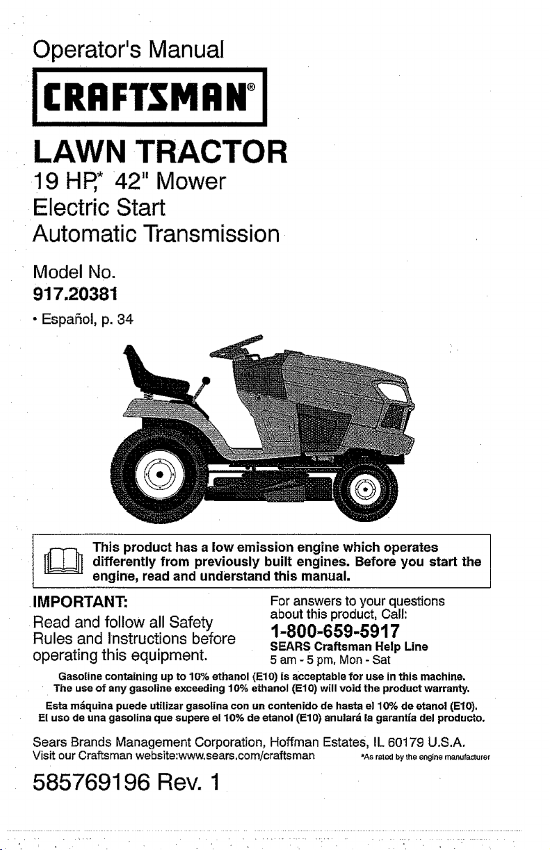
Operator's Manual
flH°
LAWN TRACTOR
19 HR* 42" Mower
ElectricStart
Automatic Transmission
Model No.
917.20381
• EspaSol, p. 34
[_ This product has a low emission engine which operatesdifferently from previously built engines. Before you start the
engine, read and understand this manual.
,IMPORTANT: For answers to your questions
Read and follow all Safety about this product, Call:
Rules and Instructions before 1-800-659-5917
operating this equipment. 5 am - 5 pm, Mon - Sat
Gasoline containing up to 10% ethanol (El0) is acceptable for use in this machine.
The use of any gasoline exceeding 10% ethanol (El0) will void the product warranty.
Esta mdquina puede utiUzar gasolina con un contenido de hasta el 10% de etanol (El0},
El uso de una gasolina que supere el 10% de etanol (El0) anulard la garantla del producto.
Sears Brands Management Corporation, Hoffman Estates, IL 60179 U.S.A.
Visit our Craftsman website:www.sears.com/craftsman *Asratedbytitleenginemanufacturer
SEARS Craftsman Help Line
585769196 Rev. 1
Page 2
Warranty .................................................. 2
Safety Rules ............................................ 3
Product Specifications ............................. 6
Assembly/Pre-Operation ......................... 7
Operation ................................................. 9
Maintenance .......................................... 16
Service and Adjustments ....................... 21
Storage .................................................. 28
Troubleshooting ..................................... 29
Sears Service ......................... Back Cover
Maintenance Schedule .......................... 16
Craftsman Riding Equipment Warranty
CRAFTSMAN FULL WARRANTY
FOR TWO YEARS from the date of purchase, all non-expendable parts of this ridingequipment are
warranted against any defects in material or workmanship. A defective non-expendable part will
receive free in-home repair or replacement if repair is impossible.
FOR FIVE YEARS from the date of purchase, the frame and front axle of this riding equipment are
warranted against any defects in material or workmanship. A defective frame or front axle will receive
free in-home repair or replacement if repair is impossible.
FOR 90 DAYS from the date of purchase, the battery (an expendable part) of this riding equipment
is ,warranted against any defects in material or workmanship (our testing proves that it will not hold a
charge). A defective battery -willreceive free in-home replacement.
ADDITIONAL LIFETIME LIMITED WARRANTY on CAST IRON FRONT AXLE (if equipped)
FOR AS LONG AS IT IS USED by the originalowner after thefifthyear from the date of purchase, the
cast ironfront axle (ifequipped) of thisriding equipment iswarranted against any defects inmaterial or
workmanship.With proofofpurchase,a defective cast front axle willreceivefree in-home replacement.
WARRANTY SERVICE
Forwarranty coverage detailsto obtain free repair or replacement, cal! 1-800-659-5917 or visit the
web site: www,craftsman.com
Inall cases above, if part repairor replacement is impossible,the riding equipmentwill be replaced
free of charge withthe same or an equivalent model.
All of the above warranty coverage is void if this riding equipment is ever used while providing
commercial servicesor if rented to another person.
This warranty covers ONLY defects in material and workmanship. Warranty coverage does NOT
include:
• Expendable parts (except battery)that can wear outfrom normal use withinthe warranty period,
including butnot limitedto blades, spark plugs,air cleaners, belts, and oil filters.
• Standard maintenance servicing, oilchanges, or tune-ups.
• Tire replacement or repair caused by punctures from outside objects, such as nails, thorns,
stumps, or glass.
- Tire or wheel replacement or repair resulting from normal wear, accident, or improper operationor
maintenance.
, Repairs necessary because of operator abuse, including but not limited to damage caused by
towing objects beyond the capability of the riding equipment, impacting objects that bend the
frame, axle assembly or crankshaft, or over-speeding the engine.
• Repairs necessary because of operator negligence, including but not limited to, electrical and
mechanical damage caused by improper storage, failure to use the proper grade and amount
of engine oil, failure to keep the deck clear of flammable debris, or failure to maintain the riding
equipment according to the instructions contained in the operatoCs manual.
• Engine (fuel system) cleaning or repairs caused by fuel determined to be contaminated or oxidized
(stale). tn general, fuel should be used within 30 days of its purchase date.
° Normal deterioration and wear of the exterior finishes, or product label replacement.
This warranty gives you specific legal rights, and you may also have other rights which vary from
state to state.
Sears Brands Management Corporation, Hoffman Estates, IL 60179
2
Page 3
_JLDANGER: This cutting machine is capable of amputating hands and feet and
throwing objects. Failure to observe the following safety instructions could result
in serious injury or death.
_WARNING: inordertopreventacciden- •
tal starting when setting up, transporting,
adjusting or making repairs, always discon-
nect spark plug wire and place wire where
it cannot contact spark plug.
_ILWARNING: Do not coast down a hill in .
neutral, you may lose control of the tractor.
_JkWARNING: Tow only the attachments
that are recommended by and comply with o
specifications of the manufacturer of your
tractor. Use common sense when towing.
Operate only at the lowest possible speed
when on a slope. Too heavy of a load,while
on a slope, is dangerous. Tires can lose
traction with the ground and cause you to
lose control of your tractor.
_t, WARNING: Engine exhaust, some of
itsconstituents, and certain vehicle compo- "
nents contain or emit chemicals known to
the State of California to cause cancer and "
birth defects or other reproductive harm.
_,WARNING: Battery posts, terminals and
related accessories contain lead and lead •
compounds, chemicals known tothe Stateof
California to cause cancer and birth defects •
or other reproductive harm. Wash hands
after handling. •
Neverdirect discharged material toward
anyone. Avoid discharging material
against a wall or obstruction. Material
may ricochet back toward the operator.
Stop the blades when crossing gravel
surfaces.
Do not operate machine without the en-
tire grass catcher, discharge chute, or
other safety devices inplace andworking.
Slow down before turning,
Never leave a running machine unat-
tended, Always turn off blades, set
parking brake, stop engine, and remove
keys before dismounting.
=
Disengage blades when not mowing.
Shut oft engine and wait for all parts to
cometo a complete stop beforecleaning
the machine,removingthe grass catcher,
or unclogging the discharge chute.
Operate machine only indaylightor good
artificial light,
Do not operate the machine while under
the influence of alcohol or drugs.
Watch for traffic when operating near or
crossing roadways.
Useextracarewhen loading or unloading
the machine into atrailer or truck.
Always weareye protection when operat-
ing machine,
Data indicates that operators, age 60
years and above, are involved in a large
I. GENERAL OPERATION
• Read, understand,andfollowallinstruc-
tions onthe machineand inthe manual
before starting.
, Do not put hands or feet near rotating
parts or under the machine. Keep clear
of the discharge opening at all times.
• Only allow responsible adults, who are
familiar with the instructions, to operate
the machine.
• Clear the area of objects such as rocks,
toys, wire, etc,, which could be picked
up and thrown by the blades,
• Be sure the area is clear of bystanders
before operating, Stop machine ifanyone
enters the area.
percentage of riding mower-related inju-
ries. These operators should evaluate
their ability to operate the riding mower
safely enoughto protect themselves and
others from serious injury.
w
Followthe manufacturer's recommenda-
tion forwheel weights orcounterweights.
o
Keep machine free of grass, leaves or
other debris build-upwhich cantouch hot
exhaust/engine parts and burn. Do not
allow the mower to plow leaves or other
debris which can cause build-up to oc-
cur.Clean any oil or fuel spillage before
operating or storing the machine. Allow
machine to cool before storage.
• Never carry passengers.
• Do not mow in reverse unless absolutely
necessary. Always look downand behind
before and while backing.
Page 4
II. SLOPE OPERATION
Slopes are a major factor related to lossof
control and tip-over accidents, which can
result in severe injury or death. Operation
on all slopes requires extra caution. If you
cannot back upthe slope or ifyoufeel uneasy
on it, do not mow it.
• Mow up and down slopes, not across.
• Watch for holes, ruts, bumps, rocks, or
other hidden objects. Uneven terrain
could overturn the machine. Tall grass
can hide obstacles.
o Choose alow ground speed so that you
will not have to stop or shift while on the
slope.
• Do net mow on wet grass. Tires may lose
traction,
Always keep the machine ingear when
going down slopes, Do not shiftto neutral
and coast downhill.
° Avoid starting, stopping, or turning on a
slope, Ifthetireslosetraction, disengage
the blades and proceed slowly straight
down the slope,
. Keep all movement on the slopes slow
and gradual. Do not make sudden
changes in speed or direction, which
could cause the machine to roll over.
• Use extra care while operating machine
with grass catchers orother attachments;
they can affect the stability of the ma-
chine. Do no use on steep slopes,
• Do not try to stabilize the machine by
putting your foot on the ground,
• Do not mow near drop-offs, ditches,
or embankments. The machine could
suddenly roll over if a wheel is over the
edge or ffthe edge caves in.
IlL CHILDREN
AOAWARNING:CHILDRENCANBEINJURED
BYTHISEQUIPMENT.The American Acade-
my of Pediatrics recommends that children
be a minimum of 12 year of age before op-
erating a pedestrian controlled lawn mower
and a minimum of 16 years of age before
operating a riding lawn mower.
Tragic accidents can occur if the operator
is not alert to the presence of children.
Children are often attracted to the machine
and the mowing activity, Never assume
that children will remain where you last
saw them.
• Keep children out of the mowing area
and in thewatchful care of a responsible
adult other than the operator,
° Be alert and turn machine off if a child
enters the area.
• Before and while backing, look behind
and down for small children.
• Never carry children,even withthe blades
shut off,They mayfalloffand beseriously
injured or interfere with safe machine
operation. Children who have beengiven
rides inthe past may suddenly appear in
the mowing area for another ride and be
run over or backed over by the machine.
• Never allow children to operate the ma-
chine.
• Use extra care when approaching blind
corners, shrubs, trees, or other objects
that may block your view of a child,
IV. TOWING
• Tow only with a machine that has a hitch
designed fortowing. Do notattachtowed
equipment except at the hitch point.
• Followthe manufacturer's recommenda-
tion forweight limits fortowed equipment
and towing on slopes.
• Never allow children or others in or on
towed equipment.
. On slopes, theweight of the towed equip-
ment may cause loss oftraction and loss
of control.
• Travel slowly andallow extra distance to
stop.
V. SERVlOE
SAFE HANDLING OF GASOLINE
To avoid personal injury or property dam-
age, use extreme care in handling gasoline.
Gasoline is extremely flammable and the
vapors are explosive.
• Extinguish all cigarettes, cigars, pipes,
and other sources of ignition.
• Use only approved gasoline container,
• Never remove gas cap or add fuel with
the engine running. Allow engine tocool
before refueling.
. Never fuel the machine indoors.
• Never storethe machine orfuel container
where there is an open flame, spark, or
pilot light such as on a water heater or
other appliances.
• Never fill containers inside a vehicle or
on atruck or trailer bed with plastic liner.
Always place containers on the ground
away from your vehicle when filling.
Page 5

• Remove gas-powered equipment from •
the truck or trailer and refuel it on the
ground, lfthis is not possible, then refuel •
such equipmentwith a portable container,
rather than from a gasoline dispenser
nozzle.
Keep the nozzle in contact with the rim •
of the fuel tank or container opening at
all times until fueling is complete. Do not
use a nozzle lock-open device. •
• Iffuelis spilled on clothing, changecloth-
ing immediately,
• Never overfill fuel tank. Replace gas cap
and tighten securely.
GENERAL SERVICE
o Never operate machine in a closed area.
• Keepall nuts and bolts tightto besure the
equipment is in safe working condition.
Nevertamperwith safety devices. Check
their proper operation regularly.
Keep machine free of grass, leaves, or
other debris build-up. Clean oil or fuel
spillage and remove anyfuel-soaked de-
bds, Allowmachine tocoolbefore storing.
If you strike a foreign object, stop and
inspectthemachine. Repair, ifnecessary,
before restarting.
Never make any adjustments or repairs
with the engine running.
Check grasscatcher components andthe
discharge chute frequently and replace
with manufacturer's recommended parts,
when necessary.
Mower blades are sharp. Wrapthe blade
or wear gloves, and use extra caution
when servicing them,
Check brake operationfrequently. Adjust
and service as required.
• Maintain or replace safety and instruction
labels, as necessary.
• Be sure the area is clear of bystanders
before operating, Stop machine ifanyone
enters the area.
• Never carry passengers,
• Do notmowin reverse unless absolutely
necessary.Always look down andbehind
before and while backing.
• Never carry children, even with the
blades shut off. They may fall off and
be seriously injured or interfere with safe
machine operation. Children who have
beengiven rides inthe pastmaysuddenly
appear in the mowing area for another
ride and be run over or backed over by
the machine.
• Keep children out of the mowing area
and in the watchful care ofa responsible
adult other than the operator.
• Be alert and turn machine off if a child
enters the area.
o Before and while backing, look behind
and down for small children.
• Mow upand down slopes (15° Max), not
across.
• Choose a tow ground speed so that you
will not have to stop or shift while on the
slope.
• Avoid starting, stopping, or turning on a
slope, Ifthetires losetraction, disengage
the blades and proceed slowly straight
down the slope.
• If machine stops while going uphill,
disengage blades, shift into reverse and
back down slowly,
• Do notturn on slopes unless necessary,
and then, turn slowly and gradually
downhill, if possible.
• When loading or unloading thismachine,
do not exceed the maximum recom-
mended operation angle of 15°.
5
Page 6
PRODUCT SPECIFICATIONS
Ga,_oline Capacity 2.50 Gallons/9,46 L
and _ype: Regular Unleaded
Oil Type: SAE 30 (above 32°F/0_C)
(API: SG-SL) SAE 5W30 (below 32°F/0°C)
Oil Capacity: W/Filter: 56 Oz.!1,65 L
Spark Plug: Champion RCI 2'(0
Charging 3 Amps Battery
System: 5 Amps Headlights
Battery: Amp/Hr: 28
Blade Belt Torque: 45-55 Ft. Lbs./62-75 Nm
W/out Filter: 48 OzJ1,4 L
(Gap: .030'70,76 mm)
Min. CCA: 230
Case size: U1R
CONGRATULATIONS onyour purchaseof
a new tractor. It has been designed, engi-
neeredandmanufactured togive you the best
possible dependability and performance.
Should you experience anyproblemyou can-
not easily remedy, please contact a Sears or
other qualified service center. We have com-
petent, well-trainedrepresentatives and the
proper tools to service or repair this tractor.
Please read and retain this manual. The
instructions will enable you to assemble
and maintain your tractor properly. Always
observe the "SAFETY RULES".
CUSTOMER RESPONSIBILITIES
• Read and observe the safety rules,
• Follow a regular schedule in maintaining,
caring for and using your tractor.
• Follow instructions under "Maintenance"
and "Storage" sections of this manual.
• Wear proper Personal Protective Equip-
ment (PPE) while operatingthis machine
including(at aminimum) sturdy footwear,
eye protection, and hearing protection,
Do not mow in shorts and/or open toed
footwear.
• Always letsomeone knowyou are outside
mowing.
_&WARNING: This tractor isequipped with
an internal combustion engine and should
not be used on or near any unimproved
forest-covered, brush-covered or grass-
covered land unless the engine's exhaust
system is equipped with a spark arrester
meeting applicable local or state laws (if
any). If a spark arrester is used, it shoutd
bemaintained in effective working order by
the operator.
Inthestate of Californiathe above isrequired
by law (Section4442 of the California Public
Resources Code). Other states may have
similar laws. Federal tawsapply on federal
lands. A spark arrester for the muffler is
availablethroughyour nearest Searsservice
center (See REPAIR PARTS manual).
REPAIR PROTECTION AGREEMENTS
Congratulations on making a smart pur-
chase, Your new Craftsman@ product is
designed and manufactured for years of
dependable operation, But like all products,
itmay require repair from timeto time. That's
when havinga Repair Protection Agreement
can save you money and aggravation.
Purchase a Repair Protection Agreement
now and protect yourself from unexpected
hassle and expense.
Here's what's includedin the Agreement:
• Expertservice by ourI2,000 professional
repair specialists.
• Unlimited service and no chargefor parts
and labor on all covered repairs.
• Product replacement if your covered
product can't be fixed.
• Discount of I0% from regular price of
service and service-related parts not
covered bythe agreement; also, t0% off
regular price of preventive maintenance
check.
• Fast help by phone - phone support
from aSears representative on products
requiring in-home repair, plus convenient
repair scheduling.
Once you purchase theAgreement, asimple
phone call isallthat ittakes for you tosched-
uleservice,You cancallanytime day ornight,
or schedule a service appointment online.
Sears has over 12,000 professional repair
specialists, who have access to over 4.5
million quality partsand accessories. That's
the kindofprofessionalismyou can count on
to help prolong the life ofyour new purchase
for years to come, Purchase your Repair
Protection Agreement today!
Some limitations and exclusions apply,
For pricesand additional information call
1-800-827.6655°
SEARS INSTALLATION SERVICE
For Sears professional installation of home
appliances, garage door openers, water
heaters, and other major home items, in the
U.S.A. call 1-800-4-MY-HOME@
Page 7
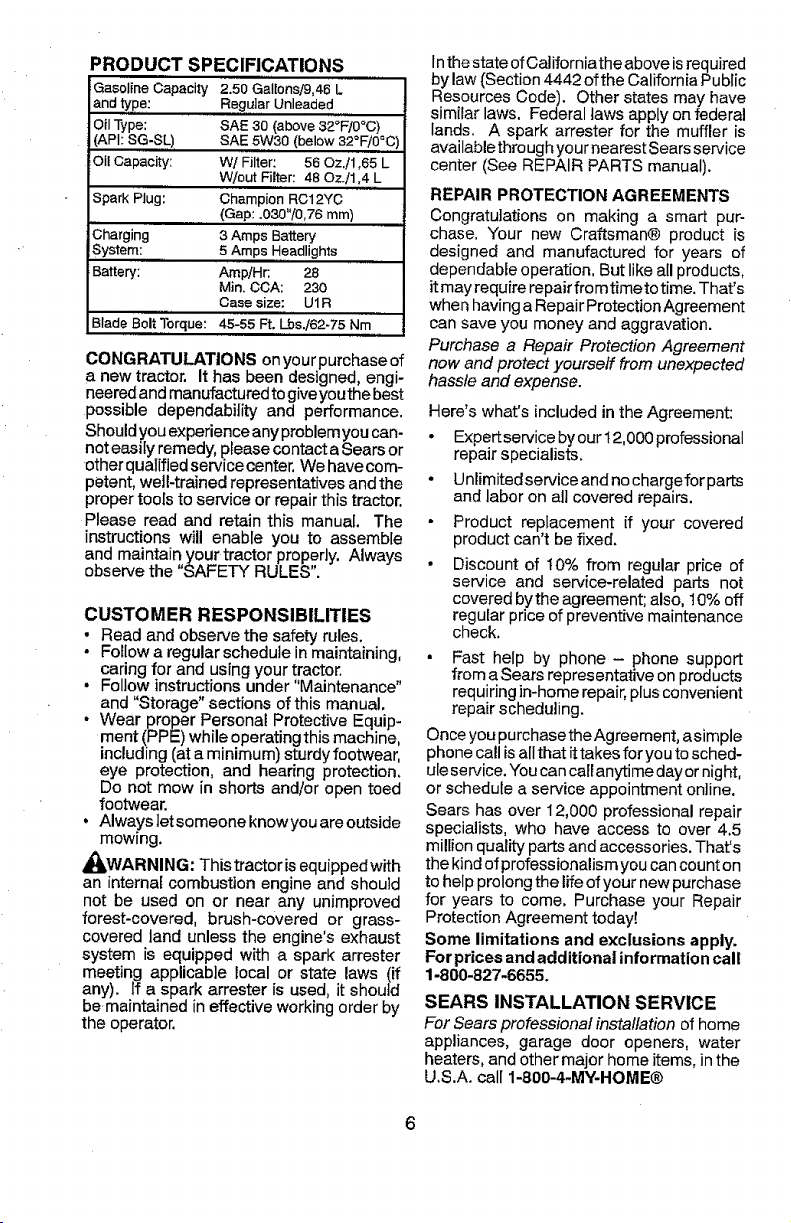
Keys Oil Drain Extension Quick Connect Slope Sheet
Your new tractor has been assembled at the factory with exception of those parts left
unassembled for shipping purposes.
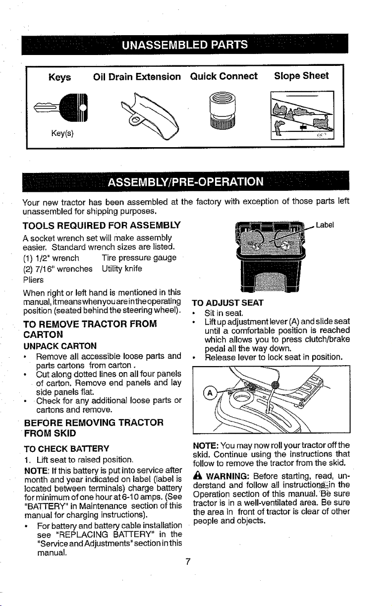
TOOLS REQUIRED FOR ASSEMBI_ Label
A socket wrench set wilt make assembly
easier, Standard wrench sizes are listed.
(1) 1/2" wrench Tire pressure gauge
(2) 7/16" wrenches Utility knife
Pliers
When right or left hand is mentioned in this
manual,itmeanswhenyou areintheoperating
position (seated behind thesteering wheel).
TO REMOVE TRACTOR FROM
CARTON
UNPACK CARTON
• Remove all accessible loose parts and
parts cartons from carton.
• Cut along dotted lines on all four panels
of carton, Remove end panels and lay
side panels flat:
• Check for any additional loose parts or
cartons and remove.
BEFORE REMOVING TRACTOR
FROM SKID
TO CHECK BATTERY
1, Liftseat to raised position,
NOTE: If this battery isput intoservice after
month and year indicated on label (label is
located between terminals) charge battery
for minimum ofone hour at 6-10 amps. (See
"BATTERY" in Maintenance section of this
manual for charging instructions),
For battery and battery cable installation people and objects.
see "REPLACING BA'I-I'ERY" in the
"Serviceand Adjustments" section inthis
manual.
TO ADJUST SEAT
• Sit in seat,
• Liftupadjustment lever(A) andslide seat
until a comfortable position is reached
which allows you to press clutch/brake
pedal all the way down.
• Release lever to lock seat in position.
NOTE: You may now roll your tractor offthe
skid. Continue using the instructions that
follow to remove the tractor from the skid.
WARNING: Before starting, read, un-
derstand and follow all instructio_in the
Operation section of this manual. 'Be sure
tractor is in a well-ventilated area. Be sure
the area in front of tractor is clear of other
7
Page 8
TO ROLL TRACTOR OFF SKID (See
Operation section for location and
function of controls)
1. Raise attachment lift lever to its highest
position,
2. Release parking brake by depressing
clutch/brake pedal.
3. Place freewheel control in "transmission
disengaged position"(See "TO TRANS-
PORT" in the Operation section of this
manual).
4, Roll tractor forward off skid.
5. Remove banding holding the deflector
shield up against tractor.
Continue with the instructions that follow.
CHECK TIRE PRESSURE
The tires on your tractor were overinflated at
the factor¢ for shipping purposes. Correct
tire pressure is important for best cutting
performance.
• Reduce tire pressure to PSI shown on
tires.
CHECK DECK LEVELNESS
For best cutting results, mower housing
should be properly leveled. See "TO LEVEL
MOWER in the Service and Adjustments
section ofthis manual,
CHECK FOR PROPER POSITION OF
ALL BELTS
See the figures that areshown for replacing
motion and mower blade drive belts in the
Service and Adjustments sectionofthis man-
ual. Verify that the belts are routed correctly,
CHECK BRAKE SYSTEM
After you learn howto operate your tractor,
check to see that the brake is operating
properly, See "TO CHECK BRAKE" in the
Service and Adjustments section of this
manual.
ti_CHECKLIST
Before you operate your new tractor, we
wish to assure that you receive the best
performance and satisfaction from this
Quality Product.
Please review the following checklist:
J All assembly instructions have been
completed.
No remaining loose parts in carton,
_/Batteryis properly preparedand charged.
d" Seat is adjusted comfortably and tight-
ened securely,
_/All tires are properly inflated. (For ship-
ping purposes,the tires were overinflated
at the factor,7).
_/Be sure mower deck is properly leveled
side-to-side/front-to-rear for best cutting
results. (Tires must be properly inflated
for leveling),
J" Check mower and drive belts. Be sure
they are routed properly around pulleys
and inside all belt keepers.
vf Checkwiring. Seethatallconnectionsare
stillsecureandwires are propedyclamped.
i/" Before driving tractor, be sure freewheel
control isin"transmission engaged" posi-
tion (see "To Transport" in the Operation
section of this manual).
Whilelearning hewto use yourtractor, pay ex-
traattention tothe following important items:
J' Engine oil is at proper level.
_/f Fueltank isfilled with fresh, clean, regular
unleaded gasoline,
_/Become familiar with all controls, their
location and function. Operate them
before you start the engine.
i/" Besure brake system isin safe operating
condition.
_/Be sure Operator Presence System and
ReVerse Operation System (ROS) are
working properly (See theOperation and
Maintenance sections in this manual).
Page 9
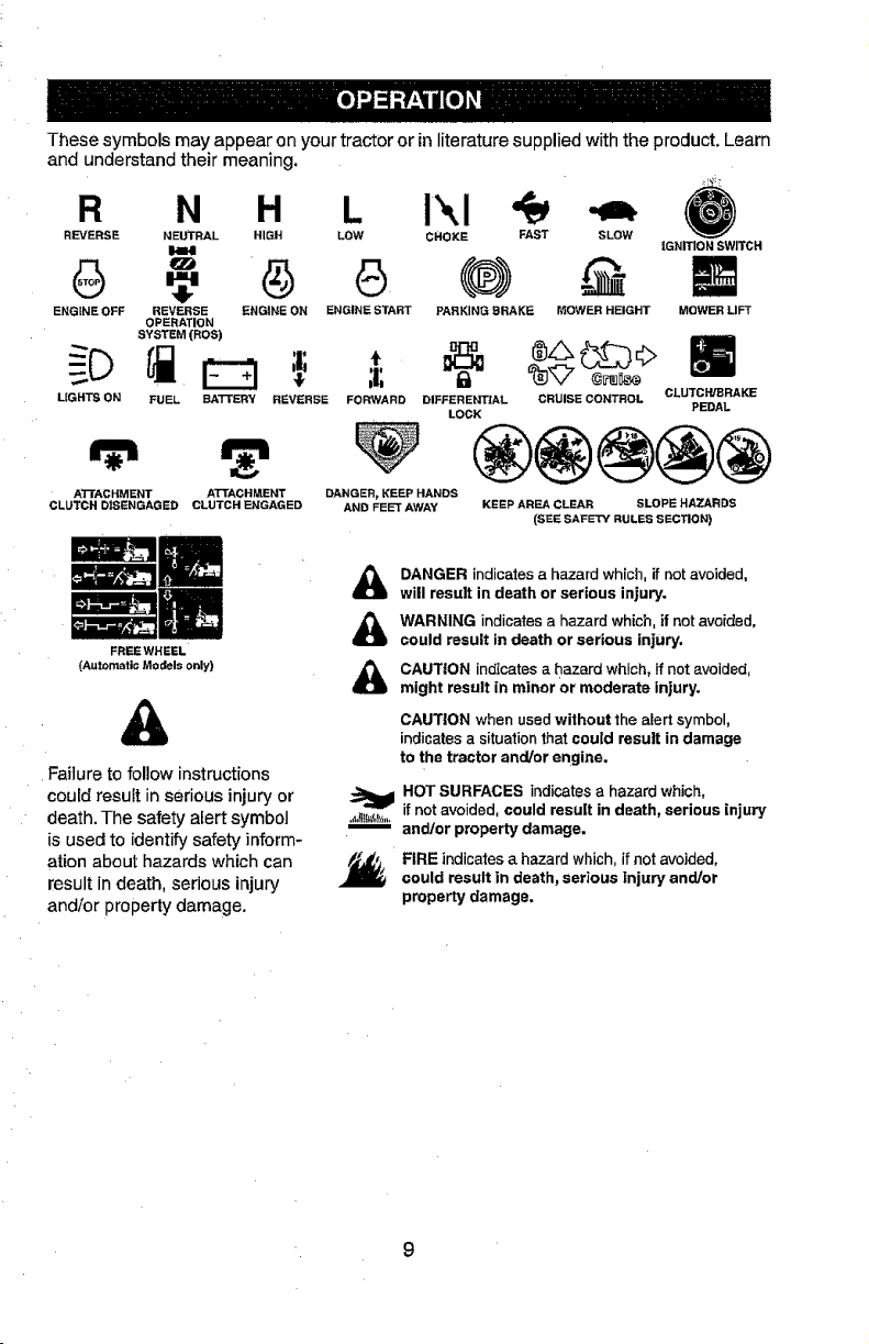
These symbols may appear on your tractor or in literature supplied with the product. Learn
and understand their meaning.
R N H L i'.,I
REVERSE NEUTRAL HIGH LOW CHOKE FAST SLOW
I1,=1,1
IGNITION SWITCH
ENGINE OFF REVERSE ENGINE ON ENGINE START PARKING BRAKE MOWER HEIGHT
LIGHTS ON FUEL BA'I-I'ERY REVERSE
ATI'ACHMENT ATTACHMENT
CLUTCH DISENGAGED CLUTCH ENGAGED
(Automatic Models only)
Failure to follow instructions
could result in serious injury or
death. The safety alert symbol ..._._,,,,m
is used to identify safety inform-
ation about hazards which can Y_,
result in death, serious injury
and/or property damage.
OPERATION
SYSTEM(ROS)
FREEWHEEL
&
,t
FORWARD DIFFERENTIAL CRUISE CONTROL CLUTCH/BRAKE
DANGER_ KEEP HANDS
AND FEET AWAY KEEP AREA CLEAR SLOPE HAZARDS
LOCK
(SEE SAFETY RULES SECTION)
DANGER indicates a hazard which, if not avoided,
will result in death or serious injury.
WARNING indicates a hazard which, if not avoided,
could result in death or serious injury.
CAUTION indicates a hazard which, if not avoided,
might result in minor Or moderate injury.
CAUTION when used without the alert symbol,
indicates a situation that could result in damage
to the tractor and/or engine.
HOT SURFACES indicates a hazard which,
if not avoided, could result in death, serious injury
andtor property damage.
FIRE indicates a hazard which, if not avoided,
could result in death, serious Injury and/or
property damage.
MOWER LIFT
PEDAL
9
Page 10
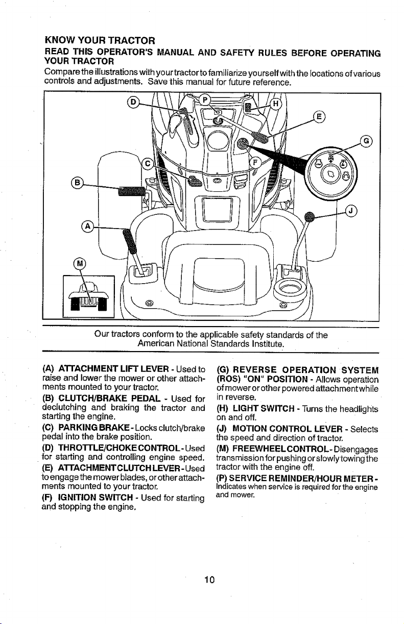
KNOW YOUR TRACTOR
READ THIS OPERATOR'S MANUAL AND SAFETY RULES BEFORE OPERATING
YOUR TRACTOR
Compare the illustrations withyourtractorto familiarize yourself with the locations of various
controls and adjustments. Save this manual for future reference.
Our tractors conform to the applicable safety standards of the
American National Standards Institute.
(A) ATTACHMENT LIFT LEVER - Used to
raise and lower the mower or other attach-
merits mounted to your tractor.
(B) CLUTCH/BRAKE PEDAL - Used for
dectutching and braking the tractor and
starting the engine,
((3) PARKING BRAKE- Locks clutch/brake
pedal into the brake position.
(D) THROTTLE/CHOKE CONTROL- Used
for starting and controlling engine speed.
(E) ATTACHMENTC LUTCH LEVER - Used
toengagethe mower blades,or otherattach-
merits mounted to your tractor.
(F) IGNITION SWITCH - Used for starting
and stopping the engine,
(G) REVERSE OPERATION SYSTEM
(ROS) "ON" POSITION - Allows operation
ofmower orotherpoweredattachmentwhile
In reverse.
(H) LIGHT SWITCH - Turnsthe headlights
on and off.
(J) MOTION CONTROL LEVER - Selects
the speed and direction of tractor.
(M) FREEWHEELGONTROL- Disengages
transmission for pushingor slowlytowingthe
tractor with the engine off.
(P) SERVICE REMINDER/HOUR METER-
Indicateswhenserviceisrequiredfor theengine
andmower.
10
Page 11
The operation of any tractor can result in foreign objects thrown into
the eyes, which can result in severe eye damage. Always wear safety
glasses or eye shields while operating your tractor or performing any
adjustments or repairs. We recommend standard safety glasses or a
wide vision safety mask worn over spectacles.
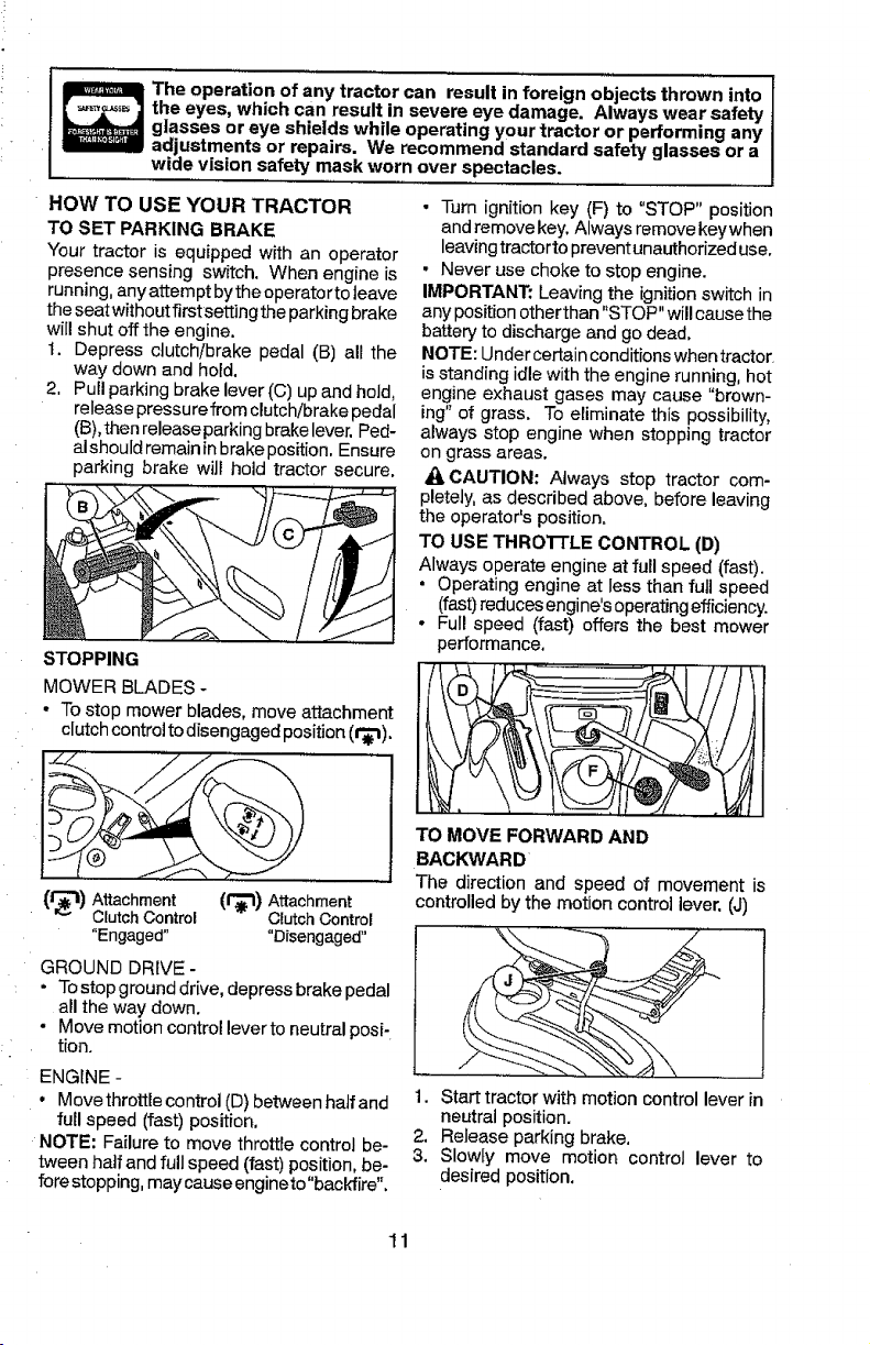
HOW TO USE YOUR TRACTOR
TO SET PARKING BRAKE
Your tractor is equipped with an operator
presence sensing switch. When engine is
running, anyattempt bythe operator toleave
the seatwithout firstsetting the parking brake
will shut offthe engine.
t. Depress clutch/brake pedal (B) all the
way down and hold.
2. Pull parkingbrake lever (C) upand hold,
release pressure from clutch/brake pedal
(B),then release parkingbrakelever,Ped-
alshould remainin brakeposition. Ensure
parking brake will hold tractor secure.
STOPPING
MOWER BLADES -
• To stop mower blades, move attachment
clutchcontrol todisengaged position (t'_).
• Turn ignition key (F) to "STOP" position
andremove key. Always remove keywhen
leavingtractorto preventunauthorized use.
• Never use choke to stop engine.
IMPORTANT: Leaving the ignition switch in
any position other than "STOP"will cause the
battery to discharge and go dead,
NOTE: Undercertain conditions when tractor
isstanding idle with the engine running, hot
engine exhaust gases may cause "brown-
ing"of grass. To eliminate this possibility,
always stop engine when stopping tractor
on grass areas.
_i.CAUTION: Always stop tractor com-
pletely, as described above, before leaving
the operator's position.
TO USE THROTTLE CONTROL (D)
Always operate engine at full speed (fast).
• Operating engine at less than full speed
(fast)reducesengine's operatingefficiency.
• Full speed (fast) offers the best mower
performance,
(f_l) Attachment (f_) Attachment
ClutchControl Clutch Control
"Engaged .... Disengaged"
GROUND DRIVE -
• To stop ground drive, depressbrake pedal
all the 'waydown.
• Move motion control lever to neutral posi-
tion.
ENGINE -
° Move throttle control (D) between half and
full speed (fast) position.
NOTE: Failure to move throttle control be-
tween half andfull speed (fast) position, be-
forestopping, maycause engineto"backfire".
TO MOVE FORWARD AND
BACKWARD
The direction and speed of movement is
controlledby the motion controllever, (J)
1. Start tractorwith motion control lever in
neutral position.
9. Release parking brake.
3. Slowly move motion control lever to
desired position.
11
Page 12
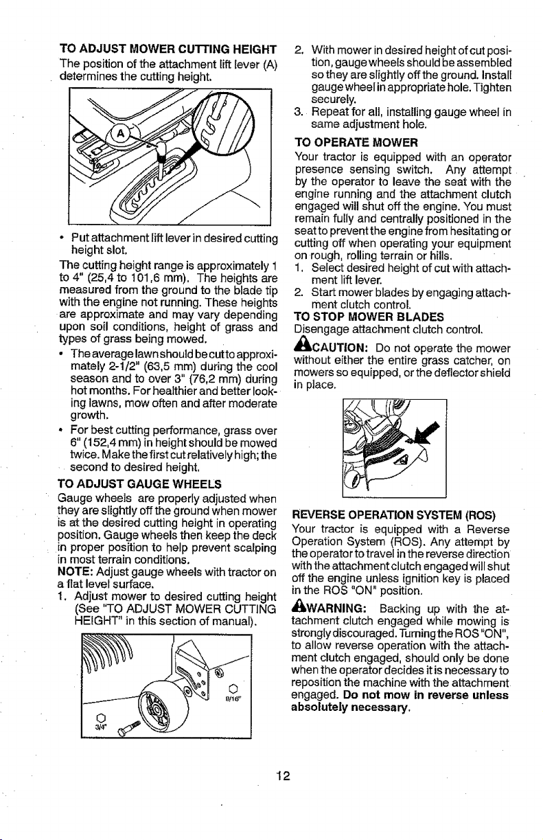
TO ADJUST MOWER CUTTING HEIGHT
The position of the attachment lift lever (A)
determines the cutting height.
- Putattachment lift lever in desiredcutting
heightslot.
The cutting height range is approximately 1
to 4" (25,4 to t 01,6 ram). The heights are
measured from the ground to the blade tip
with the engine not running. These heights
are approximate and may vary depending
upon soil conditions, height of grass and
types of grass being mowed.
• The average lawn should becutto approxi-
mately 2-1/2" (63,5 mm) during the cool
season and to over 3" (76,2 mm) during
hot months. For healthier and better look-
ing lawns, mow often and after moderate
growth.
. For best cutting performance, grass over
6" (152,4 mm) inheight should bemowed
twice. Make thefirst cut relatively high;the
second to desired height.
TO ADJUST GAUGE WHEELS
Gauge wheels are properly adjusted when
they are slightly off the ground when mower
is at the desired cutting height in operating
position. Gauge wheels then keep the deck
m proper position to help prevent scalping
in most terrain conditions.
NOTE: Adjust gauge wheels with tractor on
a flat level surface.
1. Adjust mower to desired cutting height
(See "TO ADJUST MOWER CUTTING
HEIGHT" in this section of manual).
2. With mower indesired height of cut posi-
tion, gaugewheels should beassembled
so they are slightly off the ground. Install
gauge wheel in appropriate hole. Tighten
securely.
3. Repeat for all, installing gauge wheel in
same adjustment hole.
TO OPERATE MOWER
Your tractor is equipped with an operator
presence sensing switch. Any attempt
by the operator to leave the seat with the
engine running and the attachment clutch
engaged will shut off the engine. You must
remain fully and centrally positioned in the
seat to prevent the engine from hesitating or
cutting off when operating your equipment
on rough, rolling terrain or hills.
1. Select desired height of cut with attach-
ment lift lever.
2. Start mower blades by engaging attach-
ment clutch control.
TO STOP MOWER BLADES
Disengage attachment clutch control.
_I_CAUTION: Do not operate the mower
without either the entire grass catcher, on
mowers so equipped, orthe deflector shield
in place.
REVERSE OPERATION SYSTEM (ROS)
Your tractor is equipped with a Reverse
Operation System (ROS). Any attempt by
the operator totravel in the reverse direction
with the attachment clutch engagedwillshut
off the engine unless ignitionkey is placed
in the ROS "ON" position.
_WARNING: Backing up with the at-
tachment clutch engaged while mowing is
strongly discouraged. Tumingthe ROS"ON",
to allow reverse operation with the attach-
ment clutch engaged, should only be done
when the operator decides it is necessaryto
reposition the machine with the attachment
engaged. Do not mow in reverse unless
absolutely necessary.
12
Page 13
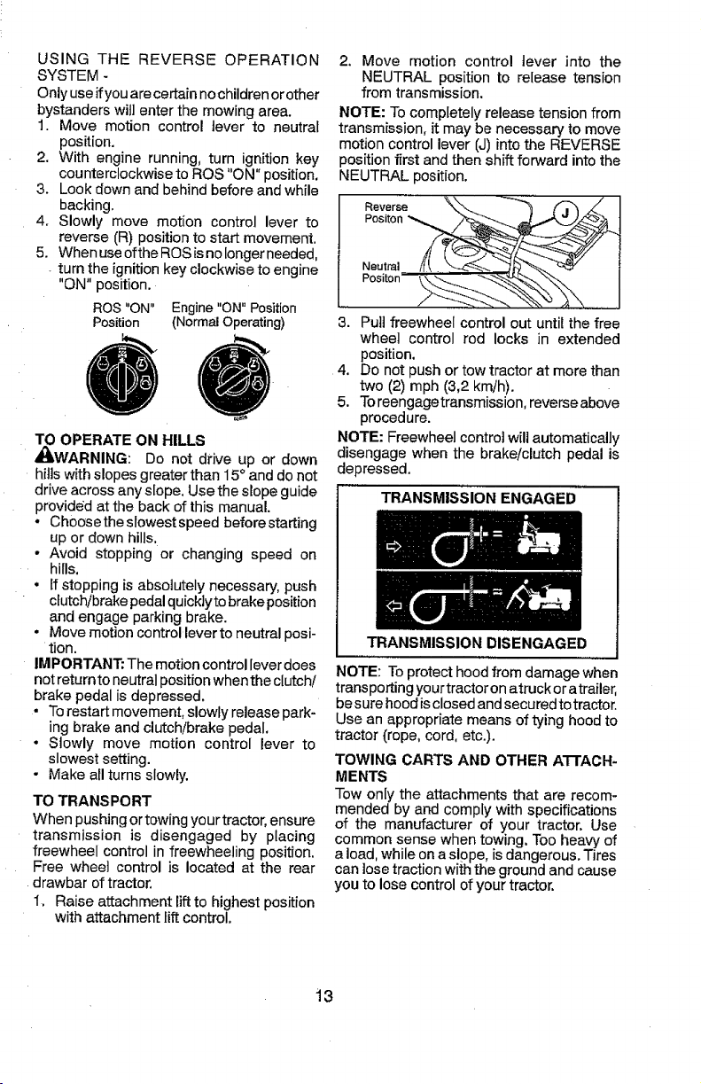
USINGTHEREVERSEOPERATION
SYSTEM-
Onlyuseifyouarecertainnochildrenorether
bystanderswillenterthemowingarea.
1.Movemotioncontrollevertoneutral
position.
2. Withenginerunning,turnignitionkey
counterclockwisetoROS"ON"position.
3. Lookdownandbehindbeforeandwhile
backing.
4. Slowlymovemotioncontrolleverto
reverse(R)positiontostartmovement.
5. WhenuseoftheROSisnolongerneeded,
turntheignitionkeyclockwisetoengine
"ON"position.
ROS"ON"Engine"ON"Position
Position(NormalOperating)
TO OPERATE ON HILLS
_WARNING: Do not drive up or down
hills with slopes greater than 15° and do not
drive across any slope. Usethe slope guide
provided at the back of this manual.
° Ch0osetheslowestspeed before starting
up or down hills.
• Avoid stopping or changing speed on
hills.
• Ifstopping is absolutely necessary, push
clutch/brake pedalquicklyto brake position
and engage parking brake.
• Move motion control lever to neutral posi-
tion.
IMPORTANT: The motion control lever does
not returnto neutral position when the clutch!
brake pedal is depressed.
• Torestart movement, slowly release park-
ing brake and clutch/brake pedal.
° Slowly move motion control lever to
slowest setting.
- Make all turns slowly.
TO TRANSPORT
When pushing or towing your tractor, ensure
transmission is disengaged by placing
freewheel control in freewheeling position.
Free wheel control is located at the rear
drawbar of tractor.
1. Raise attachment lift to highest position
with attachment fift control.
2. Move motion control lever into the
NEUTRAL position to release tension
from transmission.
NOTE: To completely release tension from
transmission, it may be necessary to move
motion control lever (J) into the REVERSE
position first and then shift forward into the
NEUTRAL position.
Reverse / I
Positon
3. Pull freewheel control out until the free
wheel control rod locks in extended
position.
4. Do not push or tow tractor at morethan
two (2) mph (3,2 km/h).
5. Toreengagetransmission, reverse above
procedure.
NOTE: Freewheel control will automatically
disengage when the brake/clutch pedal is
depressed.
TRANSMISSION ENGAGED
TRANSMISSION DISENGAGED
NOTE: Toprotect hood from damage when
transporting your tractoron atruck oratrailer,
besure hood isclosed and securedto tractor.
Use an appropriate means of tying hood to
tractor (rope, cord, etc.).
TOWING CARTS AND OTHER ATTACH-
MENTS
Tow only the attachments that are recom-
mended by and comply with specifications
of the manufacturer of your tractor. Use
common sense when towing. Too heavy of
a load, while onaslope, is dangerous. Tires
can lose traction with the ground and cause
you to lose control of your tractor.
13
Page 14
SERVICE REMINDER/HOUR METER
Service reminder shows the total number of
hourstheengine has runand indicateswhen
the engine or mower needs servicing. After
every 50 hours of operation the oil can icon
will stay on for2 hours oruntil a manual reset
occurs. To reset the display manually turn
the ignitionswitch to the on position,then
the off position five times (1 second on, 1
second of_. To service engine and mower,
see the Maintenance sectionofthis manual,
NOTE: Service reminder runs when the
ignition key is in any position but "STOP".
For accurate reading, be sure key remains
in the "STOP" position when engine is not
running.
BEFORE STARTING THE ENGINE
CHECK ENGINE OIL LEVEL
The engine in yourtractor has been shipped
from the factor,, already filled with summer
weight oil.
1. Check engine oil with tractor on level
ground.
2. Remove oil fill cap/dipstick and wipe
clean, reinsertthe dipstick and screw cap
tight, wait for afew seconds, remove and
read oil level. If necessary, add oil until
"FULl." mark on dipstick is reached. Do
not overfill.
o For cold weather operation you should
change oil for easier starting (See the oil
viscosity chart inthe Maintenance section
of this manual).
• Tochange engine oil,seethe Maintenance
section in this manual.
ADD GASOLINE
• Fill fuel tank to bottom of filler neck. Do
not overfill. Use fresh, clean, regular
gasoline with a minimum of 87 octane.
Do not mix oil with gasoline. Purchase
fuel in quantities that can be used within
_13C0 days to ensure fuel freshness.
AUTIO N:Wipe offanyspilled oilorfu el.
Do not store, spill or use gasotine near an
open flame.
IMPORTANT: When operating in tempera-
tures below 32°F (0°C), use fresh, clean
winter grade gasoline to help ensure good
cold weather starting.
CAUTION: Alcohol blended fuels (called
gasohol or using ethano] or methanol) can
attract moisture which leads to separation
andformation ofacids during storage. Acidic
gas candamage thefuelsystem ofan engine
while in storage. To avoid engine problems,
the fuel system should be emptied before
storage of 30 days or longer. Drain the gas
tank, start the engine and let it run until the
fuel lines and carburetor are empty. Use
fresh fuel next season. See Storage Instruc-
tions for additional information. Never use
engine or carburetor cleaner products inthe
fuel tank or permanent damage may occur.
Fuel stabilizer is anacceptable alternative in
minimizingthe formation offuel gumdeposits
during storage. Add stabilizer to gasoline in
fuel tank or storage container. Always follow
the mix ratio found on stabilizer container.
Runengine at least 10 minutes after adding
stabilizer to allow the stabilizer to reach the
carburetor. Do not empty the gas tank and
carburetor if using fuel stabilizer.
14
Page 15
TO START ENGINE
When starting the engine for the first time or
if the engine has run out of fuel, it will take
extra cranking time to move fuel from the
tank to the engine.
1. Ensure freewheel control is inthe trans-
mission engaged position.
2. Siton seat in operating position, depress
clutch!brake pedaland setparkingbrake.
:3. Place motion control lever in neutral
position.
4. Move attachment clutch to disengaged
position.
5. Move throttle control to choke position.
NOTE: Before starting, read the warm and
cold starting procedures below.
6. Insert key into ignition and turn key
clockwise to start position and release
key as soon as engine starts. Do not run
starter continuously for more than fifteen
seconds per minute, If the engine does
not start after several attempts, move
throttle control to fast position, wait a
few minutes and try again. If engine still
does not start, move the throttle control
back to the choke position and retry.
WARM WEATHER STARTING
(50°F (10°C) and above)
7. When engine starts, move the throttle
control to the fast position.
• The attachments and ground drive
can now be used. If the engine does
not accept the load, restart the engine
andallow itto warm upfor one minute
using the choke as described above.
COLD WEATHER STARTING
(50°F (10°C) and below)
7. When enginestarts, leavethrottle control
in choke position until engine warms up
and begins to run roughly. Once rough •
running begins, immediately move the
ithrottle controltothefastposition. Engine
warm-up maytake from several seconds
to several minutes (the colder the tern- .
perature, the longer the warm-up).
AUTOMATIC TRANSMISSION WARM UP
Before driving the unit in cold weather, the
transmission should be warmed up as fol-
lows:
1. Ensure the tractor is on level ground. °
2. Place the motion control lever in neutral.
Release the parking brake and let the
clutch/brake slowly return to operating
position.
15
3. Allow one minute for transmission to
warm up. This can be done during the
engine warm up period.
• The attachments can also be used dur-
ing the engine warm-up period after the
transmission has been warmed up.
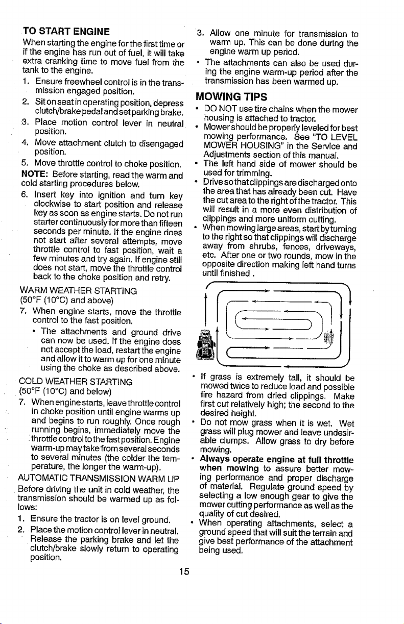
MOWING TIPS
• DO NOT use tire chains when the mower
housing is attached to tractor.
• Mower should be properly leveled for best
mowing performance. See "TO LEVEL
MOWER HOUSING" in the Service and
Adjustments section of this manual.
• The left hand side of mower should be
used for trimming.
- Drive sothatclippings are discharged onto
the area that has already been cut. Have
the cut area tothe right of the tractor. This
will result in a more even distribution of
clippings and more uniform cutting.
• When mowing targe areas,start byturning
tothe right so that clippings will discharge
away from shrubs, fences, driveways,
etc. After one or two rounds, mow in the
opposite direction making left hand turns
until finished.
if grass is extremely tall, it should be
mowed twice to reduce load and possible
fire hazard from dried clippings, Make
first cut relatively high; the second to the
desired height.
Do not mow grass when it is wet. Wet
grass will plug mower and leave undesir-
able clumps. Allow grass to dry before
mowing.
Always operate engine at full throttle
when mowing to assure better mow-
ing performance and proper discharge
of material. Regulate ground speed by
selecting a low enough gear to give the
mower cutting performance aswelt as the
quality of cut desired.
When operating attachments, select a
ground speed that will suit the terrain and
give best performance of the attachment
being used.
Page 16
MAINTENANCE BEFORE _Rv eveRY EV_RY eVeRY eVERY SE_One
SCHEDULE EACH 8 _S too e_ASOR STORAGE
Check Brake Operation .............. _
Check Tire Pressure .... •
Check Operator Presence & ROS Systems V'
A Check for Loose Fasteners _## if if
C ChecldReptace Mower Blades V'3
T Lubrication Chart if ,,, If ,
0 Check Batter,,/Level .....................
R Clean Batt_,_,,a,ndTerminals V' V'
CJe.an..D,,eb[!s,Off ,Steering Plate
Check Mower Levelness if
I Check V-Belts t,w#'
! Check Enqine Oil Level ..............if ........... if,,
Change Engine Oil (models with 0il f!!t,s,r} ................ V_._ V'
Cha_ge Ee_,!,_eQil (models without oil filter
Clean Air Filter V'_
ill i i
USE HOURS HOURS HOURS HOURS
G Clean Air Screen Ikd_
I inspect Muffler]Spark Attester
U Repla¢_ Oil Filter (|f equipped) ............ " _._
E Clean Engine Coo ing Fins Ik# 2
R._p!,a._S_arkP=ug V' V
Replace Air Filter Paper Cedridge V'2
Replace Fuel Filter _ .........
GENERAL RECOMMENDATIONS
The warranty onthistractordoes not cover
items that have been subjectedto operator
abuse or negligence. To receivefull value
from the warranty,operator must maintain
tractor as instructedinthismanual,
Some adjustments will need to be made
periodicallytoproperlymaintain yourtractor.
At least once a season, check to see if
you should make any of the adjustments
described in the Service and Adjustments
sectionof this manual,
• At least once a year youshouldreplace
the spark plug, clean or replace air filter,
and check blades and belts for wear, A
newspark plugand cleanairfitter assure
properair-fuel mixture and help your en-
gine run better and last longer.
BEFORE EACH USE
1, Check engine oil level.
2. Check brake operation,
3. Check tire pressure.
4. Check operator presence and
ROS systems for proper operation.
5. Check for loose fasteners.
LUBRICATION CHART
_Steering PivotBolts
@ Spindle----_-_l-----@ Spindle
Zerk ___ Zerk
(_Front/ -_Z_J__, \ t__L___ .
Wheel _-rom
Bearng _:_L _V_heel
. I IA | "_ "--. uearlrlg
O Steering_ _ _ _:_\
Sector Ill ill] II "__
Gear I I _3', ;:_VI I <_Engine
Teeth L_ \ ,.u./_
OGeneral Purpose Grease
(_Refer to Maintenance"ENGl NE" Section.
IMPORTANT: Do not oil or greasethe pivot
points which have special nylon bearings,
Viscous lubricants will attract dust and dirt
thatwill shorten the life ofthe self-lubricating
bearings. Ifyoufeel they must belubricated,
use only a dry, powdered graphite type
lubricantsparingly.
16
Page 17
TRACTOR
Always observe safety rules when perform-
ing any maintenance.
BRAKE OPERATION
If tractor requires more than 5 feet (1,5 m)
to stop at highest speed in highest gear on
alevel, dry concrete or paved surface, then
brake must be serviced. (See "TO CHECK
BRAKE" in the Service and Adjustments
section of this manual).
TIRES
° Maintain proper air pressure in all tires
(See the side oftires for proper PSI.)
• Keep tires free of gasoline, oil, or insect
control chemicals which can harm rubber.
• Avoid stumps, stones, deep ruts, sharp
objects andother hazardsthat may cause
tire damage.
NOTE: To seal tire punctures and prevent
flat tires due to slow leaks, tire sealant may
be purchased from your local parts dealer.
Tire sealant also prevents tire dry rot and
corrosion.
OPERATOR PRESENCE SYSTEM AND
REVERSE OPERATION SYSTEM (ROS)
Be sure operator presence and reverse
operation systems are working properly. If
your tractor does not function asdescribed,
repair the problem immediately.
• The engine should not start unless the
brake pedal is fully depressed, and the
attachment clutch control is in the disen-
gaged position.
CHECK OPERATOR PRESENCE SYSTEM
• When the engine is running, any attempt
bythe operator to leave the seat without
first setting the parking brake should shut
off the engine.
. When the engine is running and the at-
tachment clutch is engaged, any attempt
by the operator to leave the seat should
shut off the engine,
• The attachment clutch should never oper-
ate unless the operator is in the seat.
CHECK REVERSE OPERATION (ROS)
SYSTEM
• When theengine isrunningwiththe ignition
switch in the engine "ON" position and the
attachment clutch engaged, any attempt
bythe operator to drive in reverse should
shut off the engine.
• When the engine isrunningwith theignition
switch in the ROS "ON" position and the
attachment clutch engaged, any attempt
bythe operator to drive inreverse should
NOT shut off the engine.
Ros "On" Engine "On" Position
Position (Normal Operating)
BLADE CARE
Forbest results mower blades mustbesharp.
Replace worn, bent or damaged blades.
A(_CAUTION: Useonlya replacementblade
approved bythe manufacturer ofyourtractor.
Using a blade not approved by the manu-
facturer of your tractor is hazardous, could
damage yourtractor andvoid your warranty.
BLADE REMOVAL
1. Raisemower to highest position to aUow
access to blades.
NOTE: Protect your hands with gloves and!
or wrap blade with heavy cloth.
2. Remove blade bolt by turning counter-
clockwise. _iii
3. Install new blade with stamped '_RASS
SIDE" facing the ground.
IMPORTANT: To ensure proper assembly,
center hole in blade must align with star on
mandrel assembly.
4. Instalf and tighten blade bolt securely
(45-55 Ft. Lbs./62-75 Nm).
IMPORTANT: Special blade bolt is heat
treated.
8tar
Center__._!HoIe __
Blade Do, "'" "_ _andrel
(Spec,.,)_ __.._ Assembly
Blade ----"-_..._
BATTERY
Your tractor has a battery chargingsystem
which is sufficientfor normal use. However,
periodic charging of the battery with an au-
tomotive charger will extend its life. -
• Keep battery and terminals clean.
• Keep battery bolts tight.
• Keep small vent holes open,
• Recharge at 6-10 amperes for 1 hour.
NOTE: The original equipment battery on
your tractor is maintenance free. Do not
attempt to open or remove caps or covers.
Adding or checking level of electrolyte is
not necessary.
17
Page 18
TO CLEAN BATTERY AND TERMINALS
Corrosionand dirt onthe batteryandterminals
can cause the battery to "leak" power.
1. Remove terminal guard.
2. Disconnect BLACK battery cable first
then RED battery cable and remove
battery from tractor.
3. Rinse the battery with plain water and
dry.
4. Clean terminals and battery cable ends
with wire brush until bright.
5. Coat terminals withgrease or petroleum
jelly.
6. Reinstall battery (See "REPLACING
BATTERY" in the Service and Adjust-
ments section of this manual).
TRANSAXLE MAINTENANCE
The transaxle was sealed at the factory and
fluid maintenance is not required for the life
of the transaxle. Should the transaxfe ever
leak or require servicing, contact your near-
est Sears or other qualified service center.
V-BELTS
CheckV-belts for deterioration and wearafter
100hours of operation and replace if neces-
sary, The belts are not adjustable. Replace
belts if they begin to slip from wear.
ENGINE
LUBRICATION
Only use high quality detergent oil ratedwith
API service classification SG-SL, Select the
oil's SAE viscosity grade according to your
expected operating temperature.
TO CHANGE ENGINE OIL
Determine temperature range expected
before oil change. All oil must meet API
service classification SG-SL.
• Ensure tractor is on level surface.
. Oil will drain more freely when warm.
• Catch oil in a suitable container.
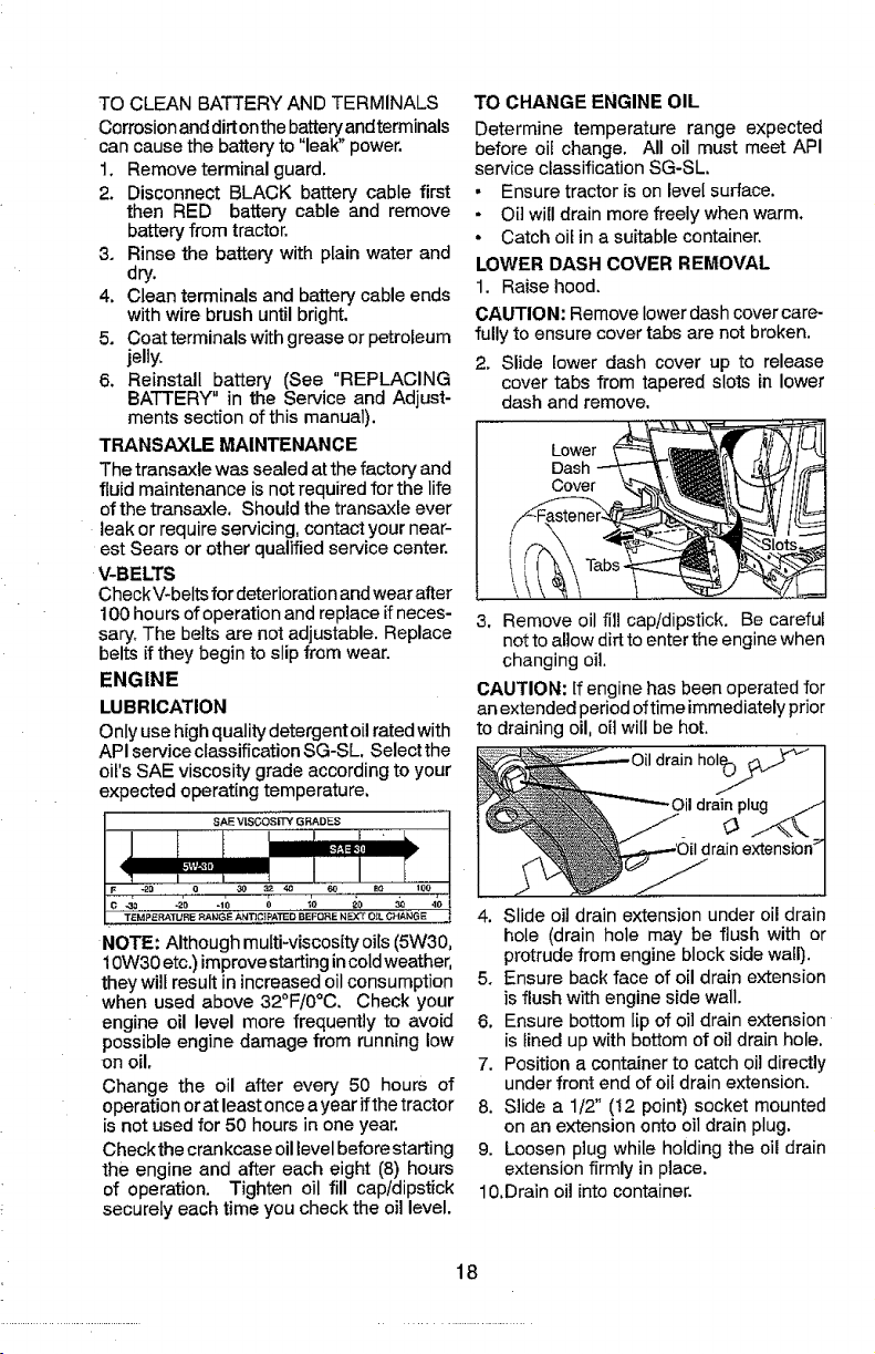
LOWER DASH COVER REMOVAL
1. Raise hood.
CAUTION: Remove lower dash cover care-
fully to ensure cover tabs are not broken.
2. Slide lower dash cover up to release
cover tabs from tapered slots in lower
dash and remove.
Lower
Dash
3. Remove oil fill cap/dipstick. Be careful
not to allow dirt to enter the engine when
changing oil.
CAUTION: If engine has been operated for
an extended period oftime immediately prior
to draining oil, oil will be hot.
drain hoI_)
NOTE; Although multi-viscosity oils (5W30,
10W30etc.) improvestarting incoldweather,
they will result in increased oil consumption
when used above 32°F/0°C. Check your
engine oil level more frequently to avoid
possible engine damage from running low
on oil.
Change the oilafterevery 50 hours of
operationoratleastonceayearifthetractor
isnotusedfor50 hoursinone year.
Checkthe crankcase oil levelbefore starting
the engine and after each eight (8) hours
of operation. Tighten oil fill cap/dipstick
securely each time you check the oil level.
drainextension>
4. Slide oil drain extension under oi! drain
hole (drain hole may be flush with or
protrude from engine block side wall).
5. Ensure back face of oil drain extension
is flush with engine side wall.
6, Ensure bottom lip of oil drain extension
is lined up with bottom of oil drain hole.
7. Position a container to catch oil directly
under front end of oil drain extension.
8. Slide a 1/2" (12 point) socket mounted
on an extension onto oil drain plug.
9. Loosen p]ug while holding the oil drain
extension firmly in place.
10.Drain oil into container.
18
Page 19
11.After oil has drained completely, reinstall
oil drain plug. (Do not tighten morethan
13 Ft, Lbs./17 Nm.)
12.Refillengine with oilthrough oilfilldipstick
tube. Pour slowly. Do not overfill. For
approximate capacity see "PRODUCT
SPECIFICATIONS" section of this
manual.
13.Usegaugeon oilfilt cap/dipstickforcheck-
inglevel. Ensure dipstick cap istightened
securely for accurate reading. Keep oil
at "FULl." line on dipstick. Tighten cap
onto the tube securely when finished,
ENGINE OIL FILTER
Replace the engine oil filter every season or
every other oil change ff the tractor is used
more than 100 hours in one year.
NOTE: If needed, remove lower dashcovers
usingstepsfrom"Lower dashcover removal"
section of this manual.
AIR FILTER
Your engine will not run properly using a
dirty air filter. Service paper cartridge every
100 hours of operation or every season,
whichever occurs first.
Service air cleaner more often under dusty
conditions.
NOTE:If needed, removelower dash covers
using steps from "Left Lower Dash Cover
Removal" section of this manual.
1. Remove cover.
2. Carefully remove air filter cartridge and
pre-cleaner from base.
3, Clean base carefully to prevent debris
from falling into carburetor,
Knobs Cartridge
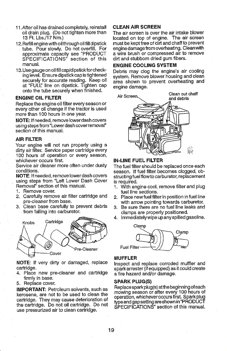
CLEAN AIR SCREEN
The air screen is over the air intake blower
located on top of engine. The air screen
must be kept free of dirt and chaff to prevent
engine damagefrom overheating. Cleanwith
a wire brush or compressed air to remove
dirt and stubborn dried gum fibers.
ENGINE COOLING SYSTEM
Debris may clog the engine's air cooling
system. Remove blower housing and clean
area shown to prevent overheating and
engine damage.
Cleanoutchaff
anddebris
_i_!_
IN-LINE FUEL FILTER
The fuel filter should be replaced once each
season. If fuel filter becomes clogged, ob-
structing fuelflowto carburetor, replacement
is required.
1. With engine cool, remove filter and plug
fuel line sections.
2. Place newfuel filter in position infuel line
with arrow pointing towards carburetor.
3. Be sure there are no fuel line leaks and
clamps are properly positioned.
4. Immediately wipe upanyspilled gasoline.
Pre-Cleaner
NOTE: If very dirty or damaged, replace
cartridge,
4. Place new pre-cleaner and cartridge
firmly in base.
5. Replace cover.
IMPORTANT" Petroleum solvents, such as
kerosene, are not to be used to clean the
cartridge. They may cause deterioration of
the cartridge. Do not oil cartridge. Do not
use pressurized air to clean cartridge.
MUFFLER
inspect and replace corroded muffler and
spark arrester (ifequipped) asit could create
a fire hazard and!or damage.
SPARK PLUG(S)
Replacespark plug(s)atthe beginningof each
mowing season or after every t00 hours of
operation, whichever occurs first. Spark plug
type andgapsetting areshownin"PRODUCT
SPECIFICATIONS" section of this manual.
19 ¸
Page 20
CLEANING
• Clean engine, battery, seat, finish, etc.
of all foreign matter.
• Clean debris from steering plate. Debris
canrestrictclutch/brakepedal shaftmove-
ment, causing belt slip and loss of drive.
& CAUTION: Avoid all pinch points and
movable parts
Clutch/brakepedal
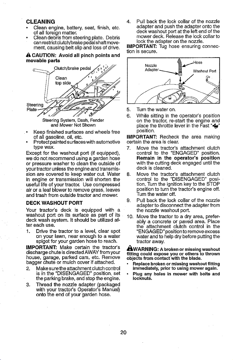
4. Pull back the lock collar of the nozzle
adapter and push the adapter onto the
deck washout port at the left end of the
mower deck. Release the lock collar to
lock the adapter on the nozzle.
IMPORTANT: Tug hose ensuring connec-
tion is secure.
Washout Port
Steering
SteeringSystem,Dash,Fender
andMowerNotShown
• Keep finished surfaces and wheels free
of all gasoline, oil, etc.
° Protect painted surfaces with automotive
type wax.
Except for the washout port (if equipped),
we do not recommend usinga garden hose
or pressure washer to clean the outside of
yourtractor unless theengine and transmis-
sion are covered to keep water out, Water
in engine or transmission will shorten the
useful life of your tractor. Usecompressed
air or a leaf blower to remove grass, leaves
and trash from outside tractor and mower.
DECK WASHOUT PORT
Your tractor's deck is equipped with a
washout port on its surface as part of its
deck wash system, It should be utilized af-
ter each use,
1. Drive the tractor to a level, clear spot
on your lawn, near enough to a water
spigot for your garden hose to reach.
IMPORTANT: Make certain the tractor's
discharge chute isdirected AWAY from your
house, garage, parked cars, etc. Remove
bagger chute or mulch cover if attached.
2. Make surethe attachment clutchcontrol
is in the "DISENGAGED" position, set
the parkingbrake, and stop the engine.
3. Thread the nozzle adapter (packaged
with your tractor's Operator's Manual)
onto the end of your garden hose.
5. Turn the water on.
6. While sitting in the operator's position
on the tractor, re-start the engine and
place the throttle lever in the Fast "._"
position.
IMPORTANT: Recheck the area making
certain the area is clear,
7. Move the tractor's attachment clutch
control to the "ENGAGED" position,
Remain in the operator's position
withthe cuttingdeckengaged untilthe
deck iscleaned.
8, Move the tractor's attachment clutch
control to the "DISENGAGED" posi-
tion. Turn the ignition key to the STOP
position to turn the tractor's engine off,
Turn the water off.
9, Pull back the lock collar of the nozzle
adapter to disconnect the adapter from
the nozzle washout port.
10. Move the tractor to a dry area, prefer-
ably a concrete or paved area. Place
the attachment clutch control in the
"ENGAGED" position to remove excess
water and to help dry before puttingthe
tractor away.
_k.WARNING: Abrokenormissingwashout
fitting couldexposeyou orothersto thrown
objectsfromcontactwiththeblade.
• Replacebrokenormissingwashoutfitting
immediately,priorto usingmoweragain.
• Plug any holes in mowerwith bolts and
Iocknuts.
20
Page 21
WARNING: TO AVOID SERIOUS INJURY, BEFORE PERFORMING ANY
SERVICE OR ADJUSTMENTS:
1, Depress clutchlbrake pedal fully and set parking brake,
2, Place motion control lever in neutral position.
3. Place attachment clutch in "DISENGAGED" position, iiiill
4. Turn ignition key to "STOP" and remove key.
5, Ensure the blades and all moving parts have completely stopped.
6. Disconnect spark plug wire from spark plug and place wire where it cannot
come in contact with plug.
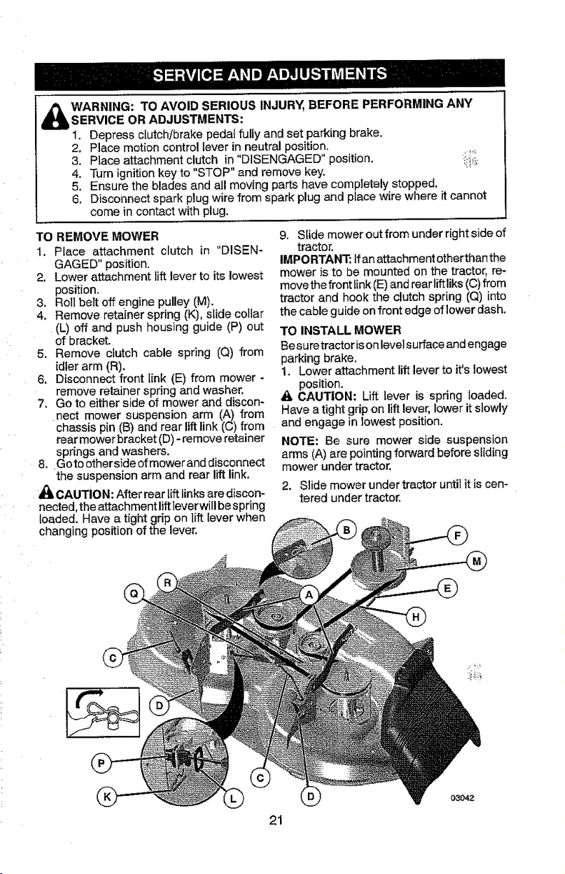
TO REMOVE MOWER
1. Place attachment clutch in "DISEN-
GAGED" position.
2. Lower attachment lift lever toits lowest
position.
3. Roll belt off engine pulley (M),
4, Remove retainer spring (K), slide collar
(L) off and push housing guide (P) out
of bracket,
5, Remove clutch cable spring (Q) from
idlerarm (R),
6. Disconnect front link (E) from mower -
remove retainer spring and washer.
7. Go to either side of mower and discon-
nect mower suspension arm (A) from
chassis pin (B) and rear lift link (C) from
rear mower bracket (D)- remove retainer
springs and washers.
8, Goto other sideof mower and disconnect
the suspension arm and rear lift link.
CAUTION: After rear liftlinks are discon-
nected, the attachmentliftleverwill bespring
loaded. Have a tight grip on lift lever when
changing position of the lever,
9. Slide mower outfrom under right side of
tractor.
IMPORTANT: tf anattachment otherthan the
mower is to be mounted on the tractor, re-
movethe front link(E)andrearliftliks ((3)from
tractor and hook the clutch spring (Q) into
the cable guide on front edge of lower dash.
TO INSTALL MOWER
Besuretractor isonlevel surfaceand engage
parking brake,
1, Lower attachment lift lever to it's lowest
position,
_, CAUTION: Lift lever is spring loaded,
Have a tight grip on lift lever, lower it slowly
and engage in lowest position.
NOTE: Be sure mower side suspension
arms (A) are pointingforward before sliding
mower under tractor.
2, Side mower undertractoruntil it is cen-
tered under tractor.
21
Page 22

3.ATTACHMOWERSIDESUSPENSION
8, Insertendoflink(E)intoholeinfront
ARMS(A)TOCHASSIS-Positionhole
inarmoverpin(B)onoutsideoftractor
chassisandsecurewithretainerspring.
4. Repeatonoppositesideoftractor.
mowerbracket(H)andsecurewith
washerandretainerspring(J).
5. ATTACHREARLIFTLINKS(C)- Lift
rearcornerofmowerandpositionslot
inlinkassemblyoverpinonrearmower
bracket(D)andsecurewithwasherand
retainerspring.
6, Repeatonoppositesideoftractor.
7, ATTACH FRONT LINK (E) - Work from
left side of tractor, Insert rod end of link
assembly through front hole in tractor
front suspension bracket (F).
9. Push clutch cable housing guide (P) into
bracket, slide collar (L) onto guide and
secure with retainer spring (K),
10. Hook end of clutch cable spring (Q) into
hole in idler arm (R).
11. Install belt onto engine clutch pulley (M).
IMPORTANT: Check belt for proper routing
in all mower pulley grooves,
12. Raise attachment lift lever to highest
position.
13. If necessary, adjust gauge wheels before
operating mower as shown inthe Opera-
tion section of this manual.
22
0_042
Page 23

TO LEVEL MOWER
Ensure tiresare properly inflatedto the PSi
shown on tires. If tires are over or under
inflated, it may affect the appearance of your
lawn and lead you to think the mower is not
adjusted properly.
VISUAL SIDE-TO-SIDE ADJUSTMENT
1. With all tires properly inflated and if your
lawn appears unevenly cut, determine
which side of mower is cutting lower.
NOTE: As desired, you can raise the low
side of mower or lower the high side.
2. Go to side of mower you wish to adjust.
3. With a 3/4" or adjustable wrench, turn
lift link adjustment nut (A) to the [eftto
lower the mower, or, to the right to raise
the mower.
Turn nut Turn nut
right to left tb
False lower
mower mower
NOTE: Each full turn of adjustment nut will
change mower height about 3/16" (4,7 ram).
4. Test your adjustment by mowing some
uncut grass and visually checking the
appearance. Readjust, ifnecessary, until
you are satisfied with the results,
PRECISION SIDE-TO-SIDE ADJUSTMENT
1, With alltires properly inflated, parktractor
on level ground or driveway.
_i, CAUTION: Blades are sharp. Protect
your hands with gloves and!or wrap blade
with heavy cloth,
2. Raise mower to its highest position.
3. At both sides of mower, position blade
at side and measure distance "A" from
bottom edge of blade toground. The dis-
tance should bethe same on bothsides.
4. Ifadjustment is necessary, see steps in
Visual Adjustment instructions above.
5. Recheck measurements; adjust ifneces-
sary until both sides are equal,
FRONT-TO-BACK ADJUSTMENT
IMPORTANT: Deck must be level side-
to-side.
Toobtain the best cutting results,the mower
blades should be adjusted so the front tip
is I/8 to t/2" (3,1 to 12,7 mm) (lower than
the rear tip when the mower is in its_highest
position.
_lliCAUTION: Blades are sharp. Protect
your hands with gloves and/or wrap blade
with heavy cloth.
* Raise mower to highest position.
. Position any blade so the tip is pointing
straight forward. Measure distance "B" to
the ground at front and rear tip of blade,
- If front tip of blade is not 1/8 to 1/2" (3,1
to 12,7 mm) lowerthan the rear tip, go to
the front of tractor.
* With an 11/16" or adjustable wrench,
loosen jam nut "A" several turns to clear
adjustment nut "B't
. With a 3/4" or adjustable wrench, turn
front link adjustment nut"B" clockwise (f_)
(tighten) to raise the front of mower, or,
counterclockwise (_) (loosen) to lower
the front mower,
Tighten adjust Loosen adjust
nut "B" to nut "B" to
raise mower lower mower
Loosenjam nut"A" first _e_
NOTE: Each full turn of adjustment nut will
change mower height about 1/8" (3,1 mm).
• Recheck measurements, adjust if neces-
sary until front tip of blade is 1/8 to 1/2"
(3,1 to 12,7 mm) lower than the rear tip.
• Hold adjustment nut in position with
wrench and tighten jam nut securely
against adjustment nut.
23
Page 24

TO REPLACE MOWER BLADE DRWE
BELT
The mower blade drive belt may be replaced
withouttools. Parkthe tractoron level sur-
face. Engage parking brake.
BELT REMOVAL -
1, Remove mewerfromtractor (See'q'O RE-
MOVEMOWER" inthissectionofmanual),
2. Work belt off both mandrel pulleys and
idlerpulleys.
3. Pull belt away from mower.
BELT INSTALLATION -
1. Work belt around both mandrel pulleys
and idler pulleys
2. Ensure belt is in all pulley grooves and
inside aUbelt guides.
3. Install mower (See "To Install Mower" in
this section of this manual).
Mandrel Idler
Pulleys
Mandrel
BELT INSTALLATION -
1. Install new belt from tractorrearto front,
over the steering plate (F) and above
clutch brake pedal shaft (G).
2. Pull belt toward front of tractor and roll
belt onto engine pulley (E).
3. Pull belt toward rear of tractor. Carefully
work belt down around transmission
cooling fan and ontothe input pulley (D).
Be sure belt isinsidethe belt keeper.
4. Installbelt on centerspan idler (C).
5. Install belt through stationary idler (A)
and clutching idler (B),
6. Make sure belt is in all pulley grooves
and inside all belt guides and keepers.
7. Install mower (See "TO INSTALL MOW-
ER" in this section of manual).
TO REPLACE MOTION DRIVE BELT
Park the tractor on level surface. Engage
parking brake. For assistance, there is a
belt installationguide decal on bottom side
of left footrest.
BELT REMOVAL -
!. Remove mower (See "TO REMOVE
MOWER" inthis section of manual).
NOTE: Observe entire motion drive belt
and position of all belt guides and keepers,
2. Remove bettfrom stationary idler (A)and
clutching idler (B).
3, Remove belt from centerspan idler (C).
6. Pull belt slack toward rear of tractor.
Carefully remove belt upwards from
transmission input pulley and over cool-
ing fan blades (D).
4. Remove belt downward from engine
pulley (E).
5. Slide belt toward rear of tractor, off the
steering plate (F)and removefrom tractor.
24
Page 25

TO CHECK BRAKE
Iftractor requires more than five (5)feet (1,5
m) to stop at highest speed in highest gear
on a level, dry concrete or paved surface,
then brake must be serviced.
You may also check brake by:
1. Park tractor on a level, dry concrete or
paved surface, depress brake pedal all
theway down andengage parking brake,
2. Disengage transmission by placing
freewheel control in "transmission dis-
engaged" position, Pullfreewheet control
out and into the slot and release so it is
held in the disengaged position.
The rear wheels must lock and skid when
you try to manually push the tractor forward.
If the rear wheels rotate, then the brake
needs to be serviced. Contact a Sears or
other qualified service center.
TO REMOVE WHEEL FOR REPAIRS
1. Block up axle securely.
2. Remove axle cover, retaining ring and
washers to allow wheel removal (rear
wheels have a square key-Do not lose),
3. Repair tire and reassemble.
NOTE: On rearwheels only: align grooves in
rear wheel huband axle. Insert square key.
4, Replacewashers and snap retaining ring
securely in axle groove.
5. Replace axle cover.
NOTE: To seal tire punctures and prevent
flat tires due to slow leaks, purchase and
use tire sealantfrom Sears. Tiresealant also
prevents tire dry rot and corrosion.
Retaining
Axle
Washers
Square
Key_ __._,
(RearWheelOnly)
FRONT WHEEL TOE-IN!CAMBER
Your new tractor front wheel toe-in and
camber is set at the factory and is normal•
The front wheel toe-in and camber are not
adjustable, If damage has occurred to
affect the factory set front wheel toe-in or
camber, contact a Sears or other qualified
service center.
TRANSAXLE MOTION CONTROL LEVER
NEUTRAL ADJUSTMENT
The motion control lever has been preset
at the factory and adjustment should not
be necessary.
1, Engage the freewheel control lever. (See
"TO TRANSPORT" in the Operations
section of this manual.) _ii__
2. Move the motion control lever _iS't,Ithe
unit rolls freely.
3. While holding motion control lever in
place, loosen the adjustment bolt.
4. Move motion control lever to the neutral
(lock gate) position.
5. Tighten adjustment bolt securely.
Motion Control Lever Neutral Lock Gate
NOTE: If additional clearance is needed to
get to adjustment bolt, move mower deck
height to the lowest position,
After above adjustment ismade, ifthe tractor
does not reach full forward or reverse speed
at the furthest motion control lever location
for forward and reverse, follow these steps.
1. Lower attachment lift lever to it's lowest
position,
2. Movethe shift plate on front oftransmis-
sion sothat the extruded area centerline
is in line with the dynamic brake arm,
3, While holding motion control lever in
place, loosen the adjustment bolt.
4. Move motion control lever to the neutral
(lock gate) position.
5, Tighten adjustment bolt Securely.
Extrusion ..... DynamicBrakeArm
25
Page 26

TO STARTENGINEWITH WEAK BATTERY
_I_WARNING: Lead-acid batteries gener-
ate explosive gases. Keep sparks, flame
andsmoking materials away from batteries.
Always wear eye protection when around
batteries.
Ifyourbattery istoo weakto startthe engine, it
should be recharged. (See"BATTERY" inthe
MAINTENANCE section of this manual).
if "jumper cables" are used for emergency
starting, follow this procedure:
IMPORTANT: Yourtractor isequipped with
a12volt system. The other vehicle must also
be a 12 volt system. Do not use your tractor
battery to start other vehicles.
TO ATTACH JUMPER CABLES -
t. Connect one end ofthe RED cableto the
POSITIVE (+)terminal of eachbattery(A-
B), taking care nottoshort against tractor
chassis.
2. Connect one end of the BLACK cable
to the NEGATIVE (-) terminal (C) of fully
charged battery.
3. Connect the other end of the BLACK
cable (D) to good chassis ground, away
from fuel tank and battery.
TO REMOVE CABLES, REVERSEORDER-
1. BLACK cablefirstfrom chassis andthen
from the fully charged battery.
2. RED cable lastfrom both batteries.
Weak or
Dead
Battery
REPLACING BATTERY
,_WARNING: Donotshort batteryterminals
by allowing a wrench or any other object to
contact both terminals at the same time.
Before connecting battery, remove metal
bracelets, wristwatch bands, rings, etc.
Positive terminal must be connected first to
prevent sparking from accidental grounding.
1. Lift seat pan to raised position.
Seat
2. DisconnectBLACK batterycablefirstthen
RED battery cable and carefully remove
battery from tractor.
3. Install newbattery with terminals in same
position as old battery.
4. First connect RED battery cable to posi-
tive (+) terminal with hex bolt and keps
nut as shown, Tighten securely. Slide
terminal cover over terminal
5, Connect BLACK grounding cable to
negative (-) terminal with remaining hex
bolt and keps nut, Tighten securely.
Terminal
Cover Keps
Hex
Bolt
26
(Red)
Cs.ble
Negative (B{ack)
Cable
Page 27

TO REPLACE HEADLIGHT BULB
1, Raise hood,
2, Remove bulb holder from the hole inthe
backside of the grill.
3, Replace bulb in holder and install bulb
holder securely back into the hole in the
backside of the grill.
4. Close hood.
INTERLOCKS AND RELAYS
Loose or damaged wiring may cause your
tractor to run PoOrly,stop running, or prevent
it from starting.
• Check wiring.
TO REPLACE FUSE
Replace with 20 amp automotive-type plug-
in fuse. The fuse holder is located behind
the dash.
TO REMOVE HOOD & GRILL ASSEMBLY
1. Raise hood.
2, Unsnap headlight wire connector.
3. Remove retainer clip and washer from
right hand pivot pin.
4. Stand in front of tractor. Grasp hood at
sides and slide left removing hood from
pivot pins and lift hood off of tractor.
5. When replacing hood, reconnect the
headlight wire connector, and reinstall
the washer and retainer clip on the
right hand pivot pin.
TRANSMISSION REMOVAL/
REPLACEMENT
Shouldyourtransmission require removal for
service or replacement, it should be purged
after reinstallation and before operating the
tractor, See "PURGE TRANSMISSION" in
the Operation section of this manual.
ENGINE
TO ADJUST THROTTLE CONTROL
CABLE
The throttle control has been preset at
the factory and adjustment should not be
necessary Check adjustment as described
below before looseningcable. If adjustment
is necessary, see engine manual.
TO ADJUST CHOKE CONTROL
The choke control has been preset at the
factory and adjustment should not be neces-
sary.If adjustment is necessary, see engine
manual.
Headlight Wire
Connector
Left Pivot Pin
Washer
•Retainer
RightPivot
Pin
27
Page 28

Immediately prepare your tractor for storage
at the end of the season or if the tractor wilt
not be used for 30 days or more,
_A.WARNING: Never store the tractor with
gasoline in the tank inside a building where
fumes may reach an open flame or spark.
Allow the engine to cool before storing in
any enclosure.
TRAOTOR
Remove mower from tractor for winter stor-
age. When mower is to bestored for a period
of time, clean it thoroughly, remove all dirt,
grease, leaves, etc. Store inaclean, dry area.
1. Clean entire tractor (See "CLEANlNG" in
the Maintenance section ofthis manual).
2. Inspect and replace belts, if necessary
(See belt replacement instructions inthe
Service and Adjustments section of this
manual).
3. Lubricate as shown in the Maintenance
section of this manual,
4. Ensure that aIt nuts, bolts and screws
are securely fastened. Inspect moving
parts for damage, breakage and wear.
Replace if necessary.
5. Touch up all rusted or chipped paint
surfaces;sand lightly before painting.
BATTERY
• Fully charge the battery for storage.
• After a period of time in storage, battery
may require recharging.
• To help prevent corrosion and power
leakage during Iong periods of storage,
battery cables should be disconnected
and battery cleaned thoroughly (see "TO
CLEAN BA'FI-ERY AND TERM INALS" in
the Maintenance section of this manual).
• After cleaning, leave cables disconnected
and place cables where they cannot come
in contact with battery terminals.
• if battery is removed from tractor for
storage, do not store battery directly on
concrete or damp surfaces.
• If unit is equipped with battery indicator/
charging plug, an optional charging unit
may be purchased and connected to the
unitto charge the battery during long term
storage. Inspect and clean the battery
terminals as needed prior to long term
storage with charger connected.
ENGINE
FUEL SYSTEM
IMPORTANT: It is important to prevent
gum deposits from forming in essential fuel
system parts such as carburetor, 1uelhose,
ortankduring storage. Also, alcohol blended
fuels (called gasohol or using ethanol or
methanol) can attract moisture which leads
to separation and formation of acids during
storage. Acidic gas can damage the fuel
system of an engine while in storage.
• Empty the fuel tank by starting the engine
and letting it run until the fuel lines and
carburetor are empty,
• Never use engine or carburetor cleaner
products in the fuel tank or permanent
damage may occur.
• Use fresh fuel next season.
NOTE: Fuel stabilizer is an acceptable al-
ternative in minimizing the formation of fuel
gum deposits during storage. Add stabilizer
to gasoline infuel tank or storage container,
Alwaysfollowthe mixratio found onstabilizer
container. Run engine at least t0 minutes
after addingstabilizer toaltowthe stabilizer to
reach the carburetor. Do not empty the gas
tank and carburetor if using fuel stabilizer,
ENGINE OIL
Drain oil('with engine warm) and replace
with clean engine oil, (See "ENGINE" inthe
Maintenance section of this manual).
CYLINDER(S)
1. Remove spark plug(s).
2. Pour one ounce (29.5 mL) of oil through
spark plug hole(s) into cylinder(s).
3, Turnignition key to "START" position for
afew seconds to distribute oil.
4, Replace with new spark plug(s).
OTHER
• Do not store gasoline from one season to
another.
• Replaceyourgasolinecan ifyourcanstarts
to rust. Rust and/or dirt in your gasoline
will cause problems.
• If possible, store your tractor indoors and
coveritto give protectionfrom dustand dirt.
• Cover your tractor with a suitable protec-
tive cover that does not retain moisture.
Do not use plastic. Plastic cannot breathe
which allows condensation to form and will
cause your tractor to rust.
IMPORTANT: Never cover tractor while
engine and exhaust areas are still warm.
28
Page 29

TROUBLESHOOTING CHART:
See appropriate section in manual unless directed to Sears service center
PROBLEM..........CAUSE
Will not start 1 Out of fuel.
2 Engine not "CHOKED" properly.
3 Engine flooded.
4 Bad spark plug.
5 Dirty air filter.
6 Dirty fuel filter.
7 Water in fuel.
8 Loose or damaged wiring.
9 Engine valves out of adjustment.
Hard to start
Engine will not
turn over
,, ,,_
J,,,,,,,,
1 Dirty air filter.
2 Bad spark plug.
3 Weak or dead batter].
4 Dirty fuel filter.
5 Stale or dirty fuel
6 Loose or damaged wiring.
7 Engine valves out of adjustment.
1 Clutch/brake pedai not depressed.
2 Attachment clutch isengaged.
3 Weak or dead battery.
: 4 B]own fuse..
5 Corroded battery terminals.
6 Loose or damaged wiring.
i 7 Faulty ignition switch.
8 Faulty solenoid or starter.
g Faulty operator presence
switch(as).
CORRECTION
1 Fill fuel tank.
2 See "TO START ENGINE" in
Operation section.
3 Wait several minutes before
attempting to start.
4 Rep|ace spark plug.
5 CleanJrep]aee air filter,
6 Replace fuel filter.
7 Empty fuel tank and carburetor,
refiI| tank with fresh gasoline and
replace fuel filter.
8 Check all wiring.
9 Contact a Sears or other qualified
service center.
1 Clean/replace air fi]ter,
2 Replace spark plug.
3 Recharge or replace battery.
4 Replace fuel filter.
5 Empty fuel tank and refill tank witt"
fresh, clean gasoline.
6 Check alt wiring.
7 Contact a Sears or other qualified
service center.
1 Depress clutch/brake pedal.
2 Disengage attachment clutch.
3 Recharge or replace battery.
4 Replace fuse.
5 Clean battery terminals.
6 Check atlwiring.
7 Check/replace ignition switch.
8 Check/replace sotenoid or sta_er,
g Contact a Sears or other quat_fied
service center,
29
Page 30

TROUBLESHOOTING CHART:
See appropriate section in manual unless directed to Sears service center
PROBLEM CAUSE
,,,., .................
Engine clicks but 1 Weak or dead battery.
will not start
Loss of power
Excessive vibration
Engine continues to
run when operator
leaves seat with
2
Corroded battery terminals. ! 2
3
Loose or damaged wiring. ! 3
4
Faulty solenoid or starter, 4
1
Cutting too much grass!too fast.
2
Throttle in "CHOKE" position.
3
Build-up ofgrass, leaves and
trash under mower.
4 Dirty air filter,
5 Low oil level/dirty oil.
6 Faulty spark plug.
7 Dirty fuel filter.
8 iStale or dirty fuel.
9 Water in fuel.
10 Spark plug wire loose.
11
Dirty engine air screerCfins. 11
12
Dirty/clogged muffler. 12
13
Loose or damaged wiring. 13
t4
Engine valves out of adjustment, 14
1 Worn, bent or loose blade.
2 Bent blade mandrel.
3 Loose/damaged part(s). 3
1 Faulty operator-safety presence 1
control system.
attachment clutch
engaged
CORRECTION
1
Recharge or replace battery.
C_ean battery terminals,
Check all wiring.
Check/replace solenoid or starter.
1 Raise cutting height/reduce
speed.
2 Adjust throttle control,
.3 Clean underside of mower
housing,
4 Clean!replace air filter.
5 Check oil levellchange oil,
6 ! Clean and regap or change spark
plug.
7 Replace fuel filter,
8 Empty fuel tank and refill tank with
fresh, cIean gasoline.
9 Empty fuel tank and carburetor,
refill tank with fresh gasoline and
replace fuel filter.
10 Connect end tighten spark plug
wire.
Clean engine air screen/fins.
Clean/replace muffler.
Check all wiring.
Contact a Sears or other qualified
service center,
1 Replace blade. T{ghten blade bolt,
2 Contact a Sears or other
qualified service center.
Tighten loose part(s).
Replace damaged parts.
Check wiring, switches and
connections. If not corrected,
contact a Sears or ether qualified
service center,
_ CAUTION: DO NOT
operate machine until
problem is corrected,
3O
Page 31

TROUBLESHOOTING CHART:
See appropriate section in manual unless directed to Sears service center
PROBLEM
Poor out - uneven
cutting
Mower blades will 1
not rotate
Poor grass 1
discharge
Headlight(s) not 1 Light Switch is "OFF".
working
(if so equipped) 2 Bulb(s) or lamp(s) burned out.
,,,,,,, ,,,,,,, ,,,, , ,,
CAUSE
1 Worn. bent or loose blade,
2 Mower deck not level
3 Buildup of grass, leaves, and
trash under mower,
4 Bent blade mandrel,
Clogged mower deck vent from
build-up of grass, leaves, and
trash around mandrels.
Obstruction in clutch mechanism.
2
Worn/damaged mower drive belt
3
Frozen idler pulley,
4
Frozen blade mandrel
Engine speed too slow.
2
Travel speed too fast,
3
Wet grass,
4
Mower deck not level.
5
Low/uneven'tire air pressure,
6
Worn, bent or loose blade.
7 Buildup of grass, leaves and
trash under mower.
8 Mower drive belt worn.
9 Blades improperly installed.
10 Improper blades used,
11 Clogged mower deck vent holes
from buildup of grass, leaves, and
trash around mandrels.
3 Faulty light switch.
4 Loose or damaged wiring,
5 Blown fuse.
CORRECTION
1 Replace blade, Tighten blade bolt,
2 Level mower deck.
3 Clean underside of mower
housing.
4 Contact a Sears or other
qualified service center.
5 Clean around mandrels to
open vent holes.
1 Remove obstruction. ,_;v
2 Replace mower drive belt.
3 Replace idler pulley,
4 Contact a Sears or other
qualified service center.
1 Place throttle control in "FAST"
position.
2 Shift to slower speed.
3 Allow grass to dry before mowing.
4 Level mower deck,
5 Check tires for proper PSI.
6 Replace/sharpen blade, Tighten
blade bolt.
7 Clean underside of mower
housing.
8 Replace mower drive belt.
9 Reinstall blades sharp edge down.
10 Replace with blades listed in
this manual.
11 Clean around mandrels to
open vent holes.
1" Turn light switch "ON".
2 Replace bulb(s) or lamp(e).
3 Check/replace light switch.
4 Check wiring and connections.
5 Replace fuse.
31
Page 32

TROUBLESHOOTING CHART:
See appropriate section in manual unless directed to Sears service center
PROBLEM CAUSE
Battery will not i 1 Bad battery cell(s).
charge
Loss of drive t Freewheel control in 1 Place freewheel control in
Engine "backfires"
when turning
engine "OFF"
Engine dies when
tractor is shifted
into reverse
,,, , ,
2 Poor cable connections.
3 Faulty regulator (if sO equipped). 3 Replace regulator.
....,,,,,,, .......
4 Faulty alternator. 4 Replace alternator.
"DISENGAGED" position. "ENGAGED" position.
2 Debds on steedng plate (if 2 See "CLEANING" in the
equipped), maintenance section.
;3 Motion drive belt worn, damaged, 3 Replace motion drive belt.
or broken.
4 Axle key missing.
...... ,,,,,,,,,,
! Engine throttle control not sel_
between half and fu[I speed (fast'
position before stopping engine'
1 Reverse operation system (ROS)
is not "ON" while mower or ether
attachment is engaged.
CORRECTION ....................
,,,,,
1
Replace battery.
2
Check/clean all connections.
4 Install axle key at rear wheel. See
"TO REMOVE WHEEL '_in the
Seivice and Adjustments section.
1 Move throtUe control between
half and full speed (fast) position
before stopping engine.
1 Turn ignition key to RO8 "ON"
position. See Operation section.
NEED MORE HELP?
You'[[findtheanswerandmore on managemyhome.cem - forfree!
• ' - Find this and all your other product manuaLs online.
• Get answers from our team of home experts,
• Get a personalized maintenance plan for your home.
* Find information and tooLs to help with home projects.
manage home
b_0ughtto youby Sears
32
Page 33

SUGGESTED GUIDE FOR SIGHTING SLOPES FOR SAFE OPERATION
ONLY RIDE UP AND DOWN HILL,
NOT ACROSS HILL
15 DEGREES MAX_
down the face of slopes, never across the face. Do not mow
_L ARNING: To avoid serious injury, operate your tractor up and
siopes greater than 15 degrees. Make turns gradually to prevent
tipping or loss of control. Exercise extreme caution when
changing direction on slopes.
1. Fold this page along dotted line indicated above.
2. Hold page before you so that its left edge is vertically parallel to a tree
trunk or other upright structure.
3. Sight across the fold in the direction of hill slope you want to measure.
4. Compare the angle of the fold with the slope of the hill.
co
cO
Page 34

Garantia .......................................................... 34
Reglas de Seguridad ...................................... 35
Especificac{ones del Producto ........................ 38
MontajeiPre Operaci6n ................................... 39
Operacibn ....................................................... 4I
Mantenimiento ................................................ 48
Programa de Mantenim[ento .......................... 48
Servicio y Ajustes ........................................... 53
Almacenamiento ............................................. 60
Identificaci6n de Problemas ........................... 61
Servicio Sears .................................. Contrat_pa
Garantla para equipos tractores Craftsman
GARANT{A COMPLETA DE CRAFTSMAN
PeR DOS ANOS desde la feche de compra, todas lee panes no sustituibles de este equipo tractor estdn
garantizadas contra cua]quier defecto de mate_aI o mane de obra. Una parte no sust{tuible defectuosa
recibir_ reparaci6n o reemplazo gratuito en case si Ja reparaci6n es imposib{e.
PeR CINCO A_,IOS desde la fecha de compra, el bastidor y el eje delantem de este equipe tractor est_n
garantizados centre cualquier defecto de material e mane de obra. Un bastidor o eje deiantero defectuoso
recibird reparaci6n o reemplazo gretuito en case si la reparaci6n es imposible.
DURANTE 90 DiAS desde la fecha de compra, Ia bateda (una parte sustituible) de este equipo tractor
est_ garantizada contra cualquier defecto de material o mane de obra (nuestra prueba comprueba que no
contendr_t carga). Una bateria defectuosa recibird un reemplazo gratuito en case.
GARANTiA LIMITADA DE PeR VIDA ADIClONAL en el EJE DELANTERO DE H|ERRO COLADO (si
est_ provisto)
DUP_NTE EL TIEMPO EN QUE SE USE per el propietario original despu6s dei quinte a_o a partii"de la
fecha de compra, el eje delantero de hierro colado (si est,i provisto) de este equipo tractos est_ garantizado
contra cualquier defecto de material o mano de obra. Con el comprobante de compra, un eje delantero de
hierro toledo recibir_ un reemplazo gratuito en case.
8ERMIOlO BE GAFIANTiA
Pare conocer los detalles de la cobertura de garantia para obtener una reparaci6n o reemplazo gratuito,
tlame al 1-800-659-5917 6 visite el sitio web: www. craftsman.corn
En ratios [os cesos anteriores, si el reemplazo es imposible, el equipo tractor ser_ sustituido sin cargo con
el mismo modelo o uno equivalente.
Toda la cobertura de garantia anterior ser_ nule si este equipo tractor se utitiza alguna vez pare brindar
aervicios comerciales o si se alquila aotra persona.
Este garantia cubre UNICAMENTE defectos de materialy mano de obra. Lacobertura de garantia NO incluye:
• Panes sustituibles (excepto la bateria) que se puedan desgastar por el uso normal dentro de] periodo de
garantia incluso, pero sin limitarse a, cuchillas, buj{as, filtros de aira, correas y filtros de aceite.
• Servicios de mantenimiento est_,ndar, cambios de aceite o afinaciones.
• Reemplazo o reparaci6n de neum&ticos por pinchazos causados pot objetos extemos como clavos,
espinas, toconee o viddos.
• Reemplazo o reparaci6n de neum&ticos o ruedas por desgaste normal, accidentes o por operaci6n o
mantenimiento incorreotos.
• Reparaciones necesarias pot abuse del operador inctuso, pete sin Iimiterse a, dafios causados por
remolcar objetos que superen {a capacidad del equipo tractor, chocar contra objetos que doblen el
bastidor, el ensamble del eje o el cig_Jefal o sobrepasar la velecidad del motor.
• Reparaciones necesadas pot negligencia del operador, incluso (pero sin timitarse a ello) daSos el_ctricos
y mec_nicos causados per el almacenamiento incorrecto, por no user el grado y la cantidad correctos de
aceite de motor, pot no mantener del muelle libra de residuos inflamables o pot no mantener el equipo
tractor de acuerdo con Ias instrucciones que contiene el manual dei operador.
• bimpieza o reparaciones del motor (sistema de combustible) cuando se determina qua se us6
combustible contaminado y oxidado (sarro). En general, el combustible debe usarse dentro de los 30
dias postedorea a su compra.
• Deterioro y desgaste normal de los acabados exteriores o sustituci6n de r6tulos de productos.
Esta garantia le otorga derechos legales especificos, y usted tambi6n puede tenet otros derechos que
varian de un estado a otro.
Sears Brands Management Corporation, Hoffman Estates, IL 60179
34
Page 35

- !
A(_,PELIGRO: Esta Maquina cortadora es capaz de amputar las manosy los pies y de lanzar
objetos, si no se observan las instrucciones de seguridad siguientes se pueden producir
lesiones graves o la muerte.
_kADVERTENCIA: Siempre desconecteel a[arn-
bre de Ia bujia y p6ngalodonde nopueda entrar
en contacto con la bujia, para evitar el arranque
por accidente, durante la preparaci6n, el trans-
porte, el ajuste ocuando se hacen reparaciones.
_u_DVERTENOIA: No avance cuestaabajo apun-
to muerto ya que podria perderelcor_roldeltractor.
_IbADVERTENCIA: Remolque solarnente los
accesorios recomendados y conformes alas
caracterfsticas indicadas pot el fabricante de su
tractor. Tenga cuidado y prudencia aI utilizar el
tractor. Cuando se encuentre en un dective, oper
utilizando exclusivamente lavelocidad m&sbaja.
En caso de un declive una carga excesiva po-
dria resultar peligrosa. Los neum_.ticos pueden
perder la tracciSn con el suelo y hacede perder
el control de sutractor.
_.DVERTENCIA: Eltubo de escape det motor,
algunos de sus constituyentes y algunos com-
ponentes del vehiculo contienen o desprenden
productos qulmicos conocidos en el Estado de
California comO causa de c_.ncer y defectos al
nacimiento u otros daSos reproductivos.
_DVERTENCIA: Los bornes, terminales yac-
cesorios relativos de la bateria contienen plomo
o compuestos de plomo, productos quimicos
conocidos en el Estado de California como causa
de c&ncer y defectos al nacimiento u otros daSos
reproductivos. Lavar las manos despu_s de
maniputarlos.
I. FUNCIONAMtENTO GENERAL
- Leer, entender y seguir todas las instrucciones
sobre la m&quina yen el manual antes de
empezar.
- No poner tas manos o los pies cerca de partes
giratodas o debajo de Ia m_quina, mantener
siempre Iimpia la abertura de descarga.
- Permitir el funcionamiento de Ia rn&quina s61o
a adultos que tengan familiaridad con las
instrucciones.
• Limpiar eI &rea de objetos como piedras,
juguetes, cables, etc. que pueden ser recogi-
dos y disparados con las cuchillas.
• Asegurarse de que et _rea est@libre de otras
personas antes de poneda en marcha. Parar
Iam_.quina si atguien entra en el &rea.
• Nunca Ilevar pasajeros.
• No cortar marcha atr&s al no set absolu-
tamente necesario. Mirar siempre abajo y
delante mientras se procede atr,_s.
• Nunca dirigir eImateriaI descargado hacia ha-
die. Evitar descargar material contra paredes
u obstrucciones. Et material podrfa rebotar
hacia el operador. Parar las cuchiltas cuando
se pasan superficies de grava.
• No maneje la m&quina si no tiene la trampa
parac6spedcornpleta, la canatetade descarga
u otros dispositivos de seguridad en su lugar
yen funcionarniento.
• Ralentizar antes de girar.
• Nunca dejar una m&quina encendida sin vigi-
lancia. Apagar siempre las cuchiltas, poner el
freno de estacionamiento, parar el motor, y
quitar ]as llaves antes de bajar.
• Desenganche las hojas cuando noest@cortan°
do c6sped. Apague el motoryespere hasta que
todas tas partes se detengan porcorn'p_l@toan-
tesde [impiar [am_quina, retirar la trampa para
e__spedo destapar la canaleta de descarga.
•Hacer funcionar la mAquina s61ocon Ialuz del
dfa o luz artificial buena.
• No hacer funcionar la m&quina estando bajo
los efectos de alcohol o droga.
•Poner atencibn al tr&fico cuando se opera
cerca de calles o se cruzan.
• Poner la m&xima atenci6n al cargar o descar-
gar ]a m&quina en una caravana o cami6n.
° Uevar siempre gafas de protecci6n cuando se
hace funcionar ta m&quina.
• Los datos indican que los operadores a partir
de los 60 aSos est&n afectados por un gran
porcentaje de heridas reiativas a la conducci6n
deI cortac6sped. Estos operadores tendrian
que evaluar su habilidad de hacer funcionar
el cortacL=sped de modo lo bastante seguro
para proteger a si mismos y a otras personas
de heridas graves.
• Seguir Ias recomendaciones del fabricante
para los pesos y contrapesos de Ias ruedas.
• Mantener [a m&quina Iibre de hierba, hojas u
otros escombros que pueden tocar el tubo de
escape/partes del motor calientes y quemarse.
No permitir que el puente del cortac@sped
cargue hojas u otros residuos que pueden
causar acumulaciones. Limpiar toda salpica-
dura de aceite o carburante antes de hacer
operaciones sobre Ia m&quina o guardarla.
Dejarla enfriar antes de guardarla.
II. FUNClONAMIENTO EN PENDIENTES
[_aspendientessonel mayor factor de accidentes
relativos a la p_rdida de control y vuelco, que
puedencausarseveras heridas o muerte. Elfun-
cionamientoen pendientesrequiereunaatenci6n
extra.Si noes posiblehacer marcha atr&sen una
pendiente o si te sientes incomodo,no[a cortes.
• Cortar hacia arriba y abajo de una pendiente,
no de modo horizontal.
•Poner atenciones a los hoyos, Ias ra_s, los
bultos, las piedras uotros objetos esc'_didos,
El terreno irregular puede volcar Ia rh_.quina.
La hierba a[ta puede esconder obst&culos.
35
Page 36

• Esooger una velocidad de marcha baja de
mode que nosea necesario pararse o cambiar
estando en una pendiente.
• Nocortar Iahierba mojada. Las ruedas pueden
perder tracciSn.
Porter siempre una marcha cuando se est,.
en pendientes. No poner en punto muerto e ir
cuesta abajo.
• Evitararrancar, pararse o girar enuna pendien-
te. Si las ruedas pierden tracci6n, desconectar
Ias cuchillas y preceder despacie cuesta abajo
en la pendiente.
• Mantener todo los movimientos en las pen-
dientes Ientos y gradual No hacer cambios
repentinos de velocidad o direcci6n, ya que
pueden causar el escape de la m&quina.
• Porter Iam_xima atenci6n cuando la m&quina
funciona con captadores de hierba u otros
dispositivos enganchados; pueden afectar ta
estabilidad de fa m_.quina. No usar en pendi-
entes empinados.
• No intentar estabilizar la m&quina poniendo el
pie en el terreno.
• No cortar cerca de bajadas, cunetas y orillas.
Las m&quina puede volcarse improvisamente
si una rueda est_ en el horde o se hunde.
III, NIl;lOS
,_ILADVERTENCIA: LOS Nti_OS PUEDEN
SUFRIR DANES CON EL use DE ESTE EQUI-
PO. La Academia Estadounidense de Pediatda
(American Academy of Pediatrics) recomienda
que s01ose permita a nifios con una edad mini-
ma de 12 afros manejar m&quinas cortac@sped
manuales, y aI menos de 16 aries para manejar
tractores cortac@sped.
Si el operador no pone atenciSn a la presencia
de los nifios pueden ocurriraccidentes tr&gicos.
Los nifios a menudo est&n atrafdos per la m&qui-
nay las actividad de cortar. No dar per hecho
de que los nifios se queden adonde estaban ta
51timavez que los vistes.
* Mantener los nifios fuera del _.reade corte y
vigilados per un adulto responsable que nosea
el operador.
- Estar alerta y apagar la m_quina si un nifios
entra en el &rea.
- Antes y durante Iamarcha atr&s, mirar adeEante
y abajo para vet si hay nifios pequefios.
- Nunca Ilevar nifios, inclusosi hay las cuchillas
apagadas. Podrian caer y herirse seriamente
o interferir cone] funcionamiento seguro de ]a
m&quina, los nifios que se han I[evado prec-
edentemente pueden aparecer de pronto enel
&reade corte per otto paseo y ser atropellados
o tumbados per la m&quina.
- Nunca dejar que los nifios manipulen la m&-
quina.
• Tenet e] m_ximo cuidado cuando se acerca
a cantos ciegos, arbustos, _.rboles u otros
objetos que pueden impedir Ia vista de nifios.
iV, REMOLQUE
• Remoicar s61ocon una m&quina que tengaun
gancho disefiado para remolcar. Enganchar el
equipo o remolcar s61o en el punto dispuesto
aIefecto.
• Seguir las recomendaciones del productor con
respecto a los limites deI equipo per remolcar
y el remolque en pendientes.
• Nunca permitir que nifios u otras personas
esten dentro del equipo per remolcar.
• En pendientes, el peso deI equipo remolcado
puede causar la p_rdida de tracci6n y la p@r-
dida de control.
• Viajar despacio y dejar m&s distancia para
frenar.
V, SERVIClO
MANIPULAClON SEGURA DE LA GASOLINA
Para evitar heridas personales o daf_os a ]as
cosas, poner el m&ximo cUidado a la hera de
maniputar la gasolina. La gasolina es extremao
mente inflamable y los vapores son explosives.
• Apagar redes los cigarrillos, cigarros, pipas y
otras fuentes de ignici6n.
• Usar s6Io contenedores para gasolina aproba-
dos.
• Nunca quitar el tap6n de ]a gasolina o afiadir
carburante con el motor en marcha, dejar
enfriar el motor antes del abastecimiento de
]a gaso[ina.
• Nunca abastecer la m_quina al interior de un
local.
• Nunca guardar la m&quina o el contenedor
del carburante donde haya una llama abierta,
chispas o una luz piloto come un calentador
de agua u otros dispositivos.
° Nunca Ilenar los contenedores al interior de
un vehiculo o en una caravana o cami6n
recubiertos con un forte de pl&stico. Co[ocar
siempre los contenedores en el terreno lejos
del vehiculo cuando se est& Ilenando.
• Quitar el equipo de gas det cami6n ocaravana
y abastecerlo en el terreno. Si no es posible,
abastecer dicho equipo con un contenedor por-
t&til, m&s bien que de un surtidor de gasolina.
• Mantener ta boquUla a contacto del borde
del dep6sito de carburante o ]a abertura del
contenedor durante toda la operaci6n de
abastecimiento. No utilizar un dispositivo con
boquilla cerrada-abierta.
• Si se vierte carburante sobre la ropa, cambi-
arse ]a ropa inmediatamente.
• Nunca Ilenar el depOsito m&s de Io debido.
Volver a co!ocar el tapSn del gas y cer_ar de
mode firme.
36
Page 37

OPERACIONES DE SERVICIO GENERALES
• Nunca hacer funcionar la m&quina en un _rea
cerrada,
• Mantener todas lastuercas y pemosapretados
paraasegurarse de quetrabaja en condiciones
seguras.
° Nunca modi_car los dtspositivos deseguridad,
Controlar su correcto funcionamiento regular-
mente.
- Mantener la m_quina Iibre de hierba, hojas
u otros residuos acumulados, Limpiar las
satpicaduras de ace_te o carburante y quitar
cualquier cosa mojada con carburante. Dejar
que la m&quina se enfrle antes de guardar{a.
* Si se gotpea un objeto ajeno, hay'que pararse
e inspeccionar la m_.quina. Reparar, si es
necesario, antes de volver a poner en marcha,
- Nunca hacer ning0n ajuste o reparacibn con
el motor en funciSn.
° Verifique los componentes de la trampa para
c6sped y la canaleta de descarga con frecuem
cia y sustituya con repuestos recornendados
pot el fabricante cuando sea necesario.
- Las cuchillas del cortac@sped son afiladas.
Envolver lacuchilla, ponerse guantes y poner
la m_(ima atenci6n cuando se hacen opera-
clones en elias.
• Controlar el funcionamiento del freno frecuent-
emente. Ajustar y hacer {as operaciones de
mantenimiento cuando eso sea necesario.
• Mantener y sustituir ;as etiquetas de seguridad
e instrucci_n, cuando sea necesario.
• Asegurarse de que el z_reaest@libre de otras
personasantes de ponerla en marcha, para la
m&quina si a[guienentra en el area.
. Nun_allevar pasajeros.
• Nocort_r marcha atr_,sat noset absolutamente
necesario, Mirar siempre abajo y delante
mientras se procede atr&s.
• Nunca [levar niSos, inclusosi hay las cuchillas
apagadas. Podrian caer y herirseseriamente
o interferircon el funcionamientoseguro de la
m&quina, los ni6os que se han Itevado prec-
edentemente pueden aparecer de prontoen el
area de code porottopaseoy set atropeIlados
otumbados por Ia m&quina,
. Mantener los niSosfuera del area de corte y
vigi]adosporun adulto responsabte que no sea
eIoperador.
° Estar alerta y apagar la m_.quina si un nifios
entra en el _rea.
° Antes y durante Iamarcha atr&s, mirar adelante
y abajo para ver si hay nifios pequefios.
• Cortar hacia arriba y abajo de una pendiente
(15° Max), no de modo horizontal.
• Escoger una velocidad de marcha baja de
modo que no sea necesado pararse ocambiar
estandoen una pendiente.
• Evitararrancar,pararseo giraren unapendien-
te, Si las ruedaspierdentracci6n, desconectar
lascuchillasy procederdespacio cuesta_abajo
en Ia pendiente. :__'
• Si la m&quina se para mientras va cuesta
arriba, desconectar las cuchiilas, poner la
marcha atr&s y ir hacia atr&s despacio.
• No girar estando en pendientessi no es nece-
sado, y {uego girar despacio y gradualmente
cuesta abajo, si es posible.
. AI ¢argar odescargar Iamz_quina,nosobrepase
e__.ngulo m_ximo recomendado de 15=,
37
Page 38

ESPECIFICACIONES DEL PRODUCTO
Capacidad y Tipo 2,50 Galones/9,46L
de Gasolina: RegularSin Plomo
Tipo de Aceite SAE 30 (sobre32°F/0°0)
(API:$G-SL): SAE5W30 (deabajo32°F!0°C)
Capacidad de Con Filtro: 56 0zj1,65 L
Aceite: Sin Fittro: 48 OzJ1,4 L
Bujia Champion RC12YC
Sistemade 3Amps Baleria
Carga: 5 Ampe Lucee
Bateda: Amp/Hr: 28
Torsidn deI Perno 45-55 Ft. LbsJ62-75 Nm
de ]a Cuchilla:
FELICITACIONES por ta compra de su tractor.Ha
sidodisefiado, planificado y fabricado paradarle la
meier con_abilidadyelmejor rendimiento posible.
En el case de que se encuentre con cualquier
problema que no pueda solucionar f&citmente,
haga el favor de ponerse en contacto con un
centre de servicio Sears 0 con un otro centre de
servicio cualificado. Cuenta con representantes
bien capacitados y competentes y con las her-
ramientas adecuadas para darle servicio 0 para
reparar este tractor.
Haga el favor do leer y de guardar este manual.
Estas instruc-ciones le permitir_,n montar y man-
tener su unidad en forma adecuada, Siempre
observe las "REGLAS DE SEGURIDAD."
RESPONSABILIDADES DEL CLIENTE
• Lea y observe las reglas de seguridad.
• Siga un programa regular de mantenimiento,
cuidado y use de su tractor.
° Siga las instrucciones descritas en Ias sec-
ciones "Mantenimiento" y '_Imacenamiento"
de este manual.
• Utilice prendas de seguridad adecuadas aI
manejar la m_quina, incluidos (come minimo)
calzado deseguridad, gafas protectoras y pro-
tecci6n auditiva. No utilice pantalones cortes
y/o oalzado abierto cuando corte ta hierba.
• Informe siempre a alguien de que so dispone
a cortar la hierba en el exterior,
I(_ADVERTENOIA: Este tractor viene equipado
con un motor de combusti6n interna y no se debe
usarsobre, o cerca, de unterrano no desarrollado
cubiertode bosques, de arbustos o de c_sped,
o menos que el sistema de escape del motor
venga equipado con unamortiguador de chispas
que cumpla con tas leyes locales o estatales (si
existen). Si se usa un amortiguador de chispas,
el operador debe mantener]o en condiciones de
trabaje eficientes.
(Abertura: .030"/'0,76mm)
Min. CCA: 230
ModeloTamafio: UIR
Enel estado de California, Ia ]ey exige Ioanterior
(SecciSn 4442 del "California Public Resources
Code"). Otros estados pueden contar con otras
leyes parecidas, Las leyes federales se aplican
en la tierras federales. Su centre de Servicio m_s
cercano tiene disponible amortiguadores de chis-
pas para el silenciador. (Vea lasecci6n de Partes
de Repuesto en el manual Ingles del duefio,)
ACUERDOS DE. PROTECCION PARA
LA REPARAClON
Congratulaciones per su buena compra, Su
nuevo producto Craftsman® est& diseSado y
fabricado para funcionar de mode fiable per
touches aries, Pero come todos los productos,
puede necesitar alguna reparaciSn de tanto en
tanto. En este case tenet un Acuerdo de Protec-
ci6n para Ia Reparaci6n puede hacerles ahorrar
dinero y fastidios,
Compre ahora un Acuerdo de Proteccibn para Ia
Reparaci6n y prot_gese de molestias y gastos
inesperados.
Un Acuerdo incluye los puntos siguientes:
• Servicio experto de nuestros 12,000 espe-
cialistas profesionales en ta reparaci6n,
• Servicio ilimitado sin cargo alguno para
las partes y la mane doobra sobretodas las
reparaciones garantizadas,
• Sustituci6n del producto si su producto
garantizado no puede ser arreglado.
• Descuento de110% sobre el precio corriente
del servicio yde las partes relativas al servicio
no cubiertas per el acuerdo; tambi6n el 10%
rnenos sobre el precio corriente de un control
de mantenimiento preventive.
° Ayuda r_pida per tel_fono - soporte telef6ni-
co per parte de un representante Sears sobre
productos que requieren un arreglo en casa, y
adem&s una programaci6n sobre los arreglos
m&s convenientes.
Cuando se ha comprado el Acuerdo, basra con
una llamada telef6nica para programar el servicio.
Puede Ilamar cuando quiera, diay noche o fijar
en linea una cita para obtener el servicio, Sears
tiene m&s de 12,000 especialistas profesionates
en la reparaci6n, que tienen acceso a m_,s de
4.5 milIones de partes y accesorios de calidad.
Este es el tipo de profesionalidad con que puede
oontar para ayudar a alargar la vida det pro-
ducto que acaba de comprar, per muchos aries,
iCompre hey su Acuerdo de Protecci6n para Ia
Reparaci6n!
Se aplican algunas limitaciones y exclusiones.
Para conocer los precios y tener mbs lnfor-
macibn, Ilame al t-800-827-6655.
SERVICIO DE INSTALACION SEARS
Para la instalacidn profesionat Sears de apara-
tos de casa, puertas de garaje, calentadores de
agua y otros importantes articulos para la casa,
on U,S.A llamar a
1-800-4-MY-HOME®
38
Page 39

Llaves
(2) Llaves
Su tractor nuevo ha side montado en la f&brica con la excepci6n de aquellas partes que no se hart
montado per razones de envto.
HERRAMIENTAS NECESARIAS PARA Etiqueta
EL MONTAJE
Un juego de Ilaves de tube facititar& el montaje.
A continuaci6n se enumeran los tarnafios de las
llaves est&ndar.
(t) Llave de I/2" Cuchillo
(2) Llaves de 7/t6" Medidor de presi6n
Cuando en este manual se mencionan los t_rmi-
nos"manoderecha"o"man0 izquierda"serefierea
cuando usted se encuentra en la posici6n de eper-
aci6n (sentado!a detr_s del volante de direcci6n).
PARA REMOVER EL TRACTOR DE LA
CAJA DE CARTON
DESEMPAQUE LA CAJA DE CART(_N
Remueva todas las partes sueltas que est@n
accesibles, y las cajas de partes, de la caja
de cart6n grande.
Cortar a Io targo de las lineas de puntos en
todos los cuatro paneles de cart6n. Remover
los paneles de cierre y aplanar los paneles
Iaterales.
• Revise si hay partes sueltas adicionates o
cart6n y remu_valas.
ANTES DE REMOVER EL TRACTOR DE
LA CORREDERA
VERIFtQUE LA BATERiA
1, Levante del asiento a la posici6n levantada.
AVISO: Siesta bateria esta utilizada despu@sdel
mes y a_,oindicado sobre laetiqueta (la etiqueta
que se encuentra entre los terminales), cargue la
baterfa per un minimo de una hera a6-10 arnps.
(Vea "BATERIA°en la secci6n de Mantenimento
de este manual).
• Para instale Ia baterla, y cable de la
bateda, realice el procedim.iento descrito en ventilada. Asegurarse que Ia zona delante deI
"REEMPLAZAR LA BATERIh_'del capftulo de tractor est@libre de otras personas y objetos.
Servicio y Ajustes de este manual.
Extensi6n del aceite Accesorio del conexibn Hoja de pendiente
Pinzas
AJUSTE EL ASIENTO
t. Si_ntese sobre el asiento.
2, Levante la palanca del ajuste (A) hacia arriba
y mueva et asiento hasta que alcance una
posici6nc6moda quele permita presionar com-
pletamente sobre el pedal del embrague!freno.
3. Desconecte la palanca paratrabar el asiento
en la posici6n.
AVISO: Ahora puedesacar eltractorde _ttarima,
Continde usando Ias instrucciones que_slguen
para retJrar eltractor de Ia tarima,
_]ILADVERTENCIA: Antes de empezar, leer,
entender y seguir todas Ias instrucciones presen-
tes en la secci6n Operaciones de este manual.
Asegurarse que el tractor est_ en un &tea bien
39
Page 40

PARA HACER RODAR EL TRACTOR FUERA
DE LA CORREDERA e,tEA LA SECCI6N DE
LA OPERACION PARA LA LOCALIDAD Y LA
FUNC16N DE LOS CONTROLES)
t. Levante Ia palanca de Ievantamiento deI ac-
casorio a su posicibn m_s alta.
2. Suelte el freno de estacionamiento presion-
ando et pedal del embrague/freno.
3. Ponga el control de la rueda libre en la
posici6n de giro libre para desenganchar la
transmisi6n, (Vea "PARA TRANSPORTAR"
en la seeci6n de Operaci6n de este manual).
4. Haga rodar el tractor hacia delante fuera de
la corredera,
5. Remueva las bandas que sujetan la protec-
ci6n contra la descarga en contra deltractor.
Continuar con ]as siguientes instrucciones.
REVISION DE LA PRESION DE LAS
LLANTAS
Las tlantas en su unidad fueron infladas de-
masiado en Ia f_briea pot razones de env_o. La
presi6n de las llantas correctas es import_nte
para obtener el mejor rendimiento en el corte.
• Reduzca la presi6n de losneum_.tieosa la PSi
que se indica en estos.
REVISION DE LA NIVELACI(_N DEL
CONJUNTO
Paraobtenerlosmejores resultadoseneleorte,la
caja de lasegadoratieneque estar niveladaen la
forma adecuada. Vea"PAPA NIVELAR LA CAJA
DE LA SEGADOR_' en la secci6n de Servicio y
Ajustes de este manual.
REVISION DE LA POSICION ADECUADA
DE TODAS LAS CORREAS
Vea las figuras que aparecen para cambiar Ias
correas de impulsi6n de la cuchilla de Ia sega-
dora y de movimiento en la seeci6n de Servicio y
Ajustes deeste manual. Verifique quetas correas
sigan su paso correcto,
REVISION DEL SlSTEMA DE FRENOS
Una vez que ustedhaya aprendido a manejar su
tractor,verifique que el freno funcione correcta-
mente, Ver "PARA VERIFICAR SI FUNC]ONA
BIEN EL FRENO" en ei capltulo de servicio y
ajustes de este manual.
LISTA DE REVIS1ON
Antes de operar y de disfrutardesutractornuevo,
le deseamos que reciba el mejor rendimiento y Ea
mayor satisfaccion de este productode calidad.
Haga ef favor de revisar la lista a continuacion:
_/" Sehan completadotodaslas instruccionesde
mon_je.
J Noquedan partessueltas en la caja de cart6n.
La bateda est& preparada y cargada enforma
adecuada.
J" El asiento ha sido ajustado en forma c6moda
y apretado en forma segura.
J" Todas las llantas ban sido infladas en forma
adecuada. (Para fines de envio, las ]lantas se
infiaron demasiado en la f&brica,)
J" Asegerese que el conjunto segador est_
nivelado en forma adecuada, de lado a lado
y desde adelante hacia atr&s, para obtener los
mejores resultados en el corte. (Las IIantas
tienen qua estar infladas en forma adecuada
para Ia nivelaci6n.)
Revise las correas de impulsi6n y de la
segadora. Aseg_rese que recorran el paso
adecuado alrededor de las poleas y dentro
de tedos los fijadores de Ias correas.
J" Revise el alambrado. Fijese qua todas las
conexiones todavia est_n seguras y que tos
alambres est_n sujetos en forma adecuada.
_" Antes de conducir el tractor, aseg6rese, clue
el control de rueda libra este en la pos_c_on
de "transmisi6n enganchada" (Vea "PARA
TRANSPORTAR" en la secci6n de ta Oper-
aci6n de este manual).
AI mismo tiempo que aprende a como usar su
tractor, preste atenci6n extra a los puntos de
portancia que se presentan a continuaci6n:
Et aceite deI motor tiene que [legar al nivei
adecuado.
EIestanque de combustibletiene queestarUeno
con gasolina sin piomo regular,nuevay limpia.
J' Fami]iaricese con todos los controles - su
ubicaci6n y su funci6n. Op_relos antes de
hacer arrancar el motor.
J" Aseg0rese que el sistema de frenos est_ en
una condiciSn de operaci6n segura.
_" Asegurarse de que el Sistema de Presencia
deIOperador y elSistema de Funcionamiento
Atr&s (ROS) funcionan de modo adecuado
(Ver las Secciones de Funcionamiento y
Mantenimiento en este manual).
4O
Page 41

Estos slmbolos pueden aparecer sobre su tractor o en Ia literature proporcionada con el producto.
Aprenda y comprenda sus significados,
R N H
MARCHA ATR_,S NEUTRO ALTO BAJO
6 ,-.-" G
MOTOR "_lw" MOTOR MOTOR
APAGADO SISTEMA ENCENDIDO ENMARCHA ESTACIONAMIENTO SEGADORA DELASEGADORA
FUNGIONAMIENTO
ATR/I,S(ROS)
IXI
ESTRANGU- R,_PIDO LENTO
LAG|ON
(®)
FRENODE ALTURADELA LEVANTAMIENTO
LUTES _ ,11, _'g_' _,_,,o
E.s_.DIoA_OOMBUST.B.E _Ro.A MARO.APA_A.O_OEMA.O0PEOA_OEFRS_O,
_T,AS.AC,AADEU_.TEoRucE_o DEEMBRAGUE
®@@@@
ACCESORIODEL ACCESOR!OeEL
EMBRAGUE EM.BRAGUE
ENGANGHADO I:)ESENGANCHADO
RUEDA LIBRE
(Solamente pare los
modelersaulomat_Co)
&
No segulr Ias siguientes instrucciones
puede provocar her_das o muerte. Los
simboto$ de aviso de seguridadse utilizan
para identificar informaciones de seguridad _j,_.
relatives a peligres que puedenprovocar la
muerte, heridas graves ylo daSos a la
m._quina.
PELIt3RO,GUARDELAS
lv_NO8 YLOSPIESLEJOS MANTENGAEL PELIGROSDE
PELIGRO indica un peligroque, si no se evita,
provoca muerte o lesiones graves.
ADVERTENCIA indica un peligroque, si no se evita.,
puede provocar muerte o lesiones graves,
PRECAUCION indica un peligro que, si no se evita,
puede provocar lesiones ligeras o moderadas.
PRECAUCI(3N cuando se utilize sin el simbolo de avise,
indioa una situaciSn que puede provoear da_os at
tractor yto al motor.
_='='='='='='='='=_SUPERFICIES CALIENTES indica un peligro que,
si no se evita, puede provocar la muerte, lesiones
graves y/o danes ala mdquina.
FUEGO indica un peligro que, si no se evita, puede
provocar la muerte, leslones graves y/o danes
a la m_quina,
AREADESPEJADA PENDIENTES
(Veala secc_nde las reglasdesBguridad)
41
Page 42

FAMILIARICESE CON SU TRACTOR
LEA ESTE MANUAL DELY LAS REGLAS DE SEGURIDAD ANTES DE OPERAR SU TRACTOR
Compare Ias ilustraciones con su tractor para familiarizarse con Ias ubicaciones de los diversos
controJesy ajustes. Guarde este manual para referencia en el futuro.
Nuestros tractores cumplen con los est_ndares de seguridad del
(A) PALANCA DEL LEVANTAMIENTO DEL AC-
CESORIO - Se usa para levantar, bajar y ajustar
el conjunto segador o los dem&s accesorios
montados en sutractor.
(B) PEDAL DEL EMBRAGUF_JFRENO - Se usa
para desembragar y frenareltractory para hacer
arrancar el motor.
(C) PALANCA DEL FRENO DE ESTACIONA-
MIENTO - Asegura el pedat del embrague!freno
en la posici6n det freno.
(D) CONTROL DE AOELERACION/ESTRAN-
GULACION - Se usa para hacer arrancar y
controlar Iavelocidad del motor.
(E) PALANCA DEL EMBRAGUE DEL AC-
CESORIO - Se usa para enganchar lascuchillas
segadoras, o los demos accesonos montados
en su tractor.
American National Standard Institute,
(F) INTERRUPTOR DE IGNICI6N - Se usa para
hacer arrancar o hacer parar el motor.
(G) SlSTEMA DE FUNCIONAMIENTO HAOIA
ATRAS (ROS) EN POSICION "ON" - Permite Ia
operaci6n del conjunto segador o otro accesorio
accionado mientras queen rev@s,
(H) tNTERRUPTOR DE LA LUZ - Enciende y
apaga las lucesdelanteras.
(J) PALANCA DE CONTROL DE MOViMIENTO-
Selecciona la velocidad y la direcci6n del tractor.
(M) CONTROL DE RUEDA LIBRE - Desengan-
cha la trans-mtsi6n para empujar o arrastrar.
(P) DIS POStTIVO DE AVISO DE SERV|CIO/
CRONOMETRO - tndicacu&ndohayque hacer-
tes el servicio al motor y a la cortadora.
42
Page 43

La operaci6n de cualquier tractor puede hacer que salten objetos extra_os 1
dentro de sus ojos, Io que puede producir da_os graves en 6stos. Siempre use I
anteojos de seguridad o protecciones pars los o|os mientras opere su tractor!
io cuando haga ajustes o reparaciones. Recomendamos galas de seguddad o I
una mdscara de visi6n amplia de seguridad usada sobre las gafas, |
COMO USAR SU TRACTOR
PARA AJUSTAR EL FRENO DE ESTACIONA-
MIENTO
Sutractorviene equipado con uninterruptor sen-
sor que exige la presencia del operador. Cuando
el motor est,. funcionando, si el operador trata de
bajarse del asiento sin primero aplicar elfreno de
estacionamiento, se apagar,_ el motor.
!, Presione el pedal (D) del freno/embrague
completamente y sostenga!o.
2. Jale hacia arriba ]a palanca del freno de
mano (H) y mant_ngala en esa posici6n;
suelte gradualmente el pedal del embrague/
freno (D), y Iuego suelte la palanca del freno
de mano. El pedal tiene que quedar en Ia
posici6n de freno. Aseg_rese que et freno
de estacionamiento va a sujetar el tractor en
forms segura.
PARADA
CUCHILLAS DE LA SEGADORA -
• Mueva fa control del embrague deI accesorio
a ta posici6n desenganchado (1_1).
o Gire la Ilave de ignici6n (F) a la posici6n de
apagado "STOP" y remueva la Ilave al aban-
donar eltractor pars ev[tarel uso no autodzado.
IMPORTANTE: Dejando el interrupt o._::de la
ignici6n en cualquier posici6n otra que!;_'.STOP"
causar ique la bateda se descargue (muerta).
AVISO: Bajo ciertas condiciones, cuando el
tractor estd parado con el motor andando en
vacio, los gases de escape del motor ca]iente
pueden hacer qua el c_sped se ponga "caf_."
Pars eliminar esta posibilidad, siempre pare el
motorcuando pareeltractoren _eas con c6sped.
_,PRECAUCI6N: Siempre pare eltractor com-
pletamente, seg_n se ha descrito anteriormente,
antes de abandonar la posicibn deI operador.
PARA USAR EL CONTROL DE LA ACELER-
ACION (O)
Siempre opere el motor a una aceleraci6n
completa.
- Siel motorfunciona a una velocidad inferior a la
m_txima (r&pida), su rendimientodisminuye.
• El rendimiento 6primo seobtiene a lavelocidad
m&xima (r&pida). "
! I
(r_) "Enganchado" (l'_--'l) "Desenganc hado'°
{Engaged) (Disengaged)
'IMPULSION DE RECORRIDO -
• Pars parar el mecanismo impulsor, presione el
pedal deIfreno completamente,
• Mueva la palanca de control de movimiento (J)
a la posici6n de neutro.
MOTOR -
• Mover la palanca (D) de mando entre la
posici6ndevelocidad mediay m_xima (rdpida).
AVISO:Si no se mueve la palanca de mando
entre ta posici6nde velocidad media y m&xima
(r&pida), antes de pararse, se puede causar un
"retomo de llama" det motor.
PARA MOVERSE HACIA ADELANTE Y HACtA
ATRAS
La direcci6n y [a velocidad del movimiento son
controladas por medio de la palanca de control
de movimiento (J),
1. Hags arrancar el motor con tapalanc_'_decon-
trol de movimiento en la posici6n de neutro.
2. Suelte el freno de estacionamiento.
3. Lentamente, mueva la palanca de control de
movimiento a la posici6n deseada.
43
Page 44

PARA AJUSTAR LA ALTURA DE CORTE DE
LA SEGADORA
Laposici6nde la palanca elevadora (A) determina
a qu_ altura se cortar_ el c4sped.
• Coloque la paEancaelevadora en la ranura de
[aa[tura deseada.
La gama de la attura de corte es de aproximada-
mente 25,4to 10t,6 mm (1 a4 pulgadas). Las
alturas se rniden desde e! sue[o a la punta de la
cuchilla cuando el motor no est& funcionando.
Estas alturas son aproxirnadas y pueden variar
dependiendo de las condiciones del suelo, de la
altura de} c_sped y del tipo deI c(_sped que se
est_ segando.
• El c4sped promedio debe cortarse aproxi-
madamente a 63,5 rnm (2-t/2 pulgadas)
durante la temporada fria y sobre 76,2 mrn
(3 pulgadas) durante los meses calurosos.
Para obtener un c4sped rn&s saludab[e y de
mejor apariencia, siegue a menudo y despuL=s
de un crecimiento moderado.
• Para obtener el mejor rendimiento de corte, el
o_sped que tiene rn&sde 152,4 mm (6 pulga-
das) de altura debe segarse dos veces. Haga
el pdmer corte relativamente alto; el segundo
a ta altura deseada.
PARA AJUSTAR LAS RUEDAS CALIBRA-
DORAS
Las ruedas calibradoras est&n bien ajustadas
cuando se encuentran un poco a distancia de]
terreno aI mismo tiempo que la segadora est4 a
la altura de corte deseada. Entonces Ias ruedas
calibradoras mantienen el conjunto segador en
posici6n para prevenir el corte raspeo en cas[
todos los terrenos.
AVISO: Ajuste [as ruedas calibradoras con el
tractor en una superficie nivelada plana.
1. Ajuste la segadora a ta altura de corte
deseada con fa mani[Ia de ajuste de al-
tufa (Vea "PARA AJUSTAR LA ALTURA DE
CORTE DE LA SEGADOP_' en Ia seccibn
de Operaci6n de este manual).
2. Con la segadora a ta altura deseada para Ia
posici6n de corte, se tienen que montar las
ruedas oalibradoras de modo que queden
un poco sobre el suelo. InstaFe las ruedas
calibradoras en el agujero adecuado con el
perno con resalto, la arandela de 8/8, y la
tuerca de seguridad de 3/8-16 y apd_telos
en forma segura.
3. Repita el procedimientopara et tado opuesto
instalandola rueda caiibradora en el rnismo
agujero de ajuste.
PARA OPERAR LA SEGADORA
Su tractor viene equipada con un interruptor
sensor que exige la presencia del operador. Si
el motorest&funcionando y el ernbraguedelac-
cesorio est& enganchado y el operador trata de
bajarse deI asiento, se apagar& el motor. Tiene
que mantenerse sentado completa y central-
mente en el asiento para impedir que el motor
vacile o se apague cuando se opere su equipo
en terreno disparejo, _.spero o en cerros.
1. Elija a qu6 altura cortarz_el c_sped pormedio
de la palanoa elevadora.
2. Haga arrancar las cuchillas de la segadora
enganchando el control del embrague del
aocesorio.
PARA PARAR LAS CUCHILLAS DE LASEGA-
DORA
Desenganche el control del embrague del ac-
cesorio,
_PREOAUCIC)N: No opere la segadora sin,
ya sea, el recogedor de c4sped complete en las
segadoras asf equipadas o con la protecci6n
contra la descarga en su lugar.
FUNCIONAMIENTO ATRAS
Tu tractor est,. equipado con el Sistema de Fun-
cionamientoAtr,_s(ROS). Cualquier tentativadel
operadorde viajar marcha atr&s conel embrague
puestoapagar& el motor a menos que la Itave de
ignici6nsepongaen la posici6nde "ON"del ROS,
ATENCION: Ir marcha atr&s con el ernbrague
puesto para cortar, no es recornendable. Po-
niendoel ROSen posici6n"ON", para permitirel
funcionamiento atr&s con elernbraguepuesto,se
t[eneque hacer s6]ocuando el operadorIoconsi-
dera necesario para reposicionar Ia m&quina con
e[dispositivo embragado. No siegue en rev4s a
menos que sea absolutamente necesario.
44
Page 45

USAR EL SISTEMA DE FUNCIONAMIENTO
ATRi_S -
Ut_lice el tractor solamente Sl est& seguro de que
no [ngresar&n niOos ni otras personas o animales
al &rea donde se vaa cortar el c@sped.
1. Mover fa palanca de mando del movimiento
en la posiciOn neutro.
2,
Con el motor en marcha, girar la Ilave del inter-
ruptor de la igniciOn en et sentido inverse al
de las agujas del reioj hasta la posiciOn "ON".
3.
Mire hacla abajo y hac_a atr&s no sOlo antes
de ir marcha arras, sine mientras est6 yende
marcha atr&s.
4.
Mover despacio la pa]anca de mando del
movimiento hacla la posicidn atf_.s (R) pare
ernpezar el movimiento
5.
Cuando el use del ROSes m_,s necesario, d6
vuelta ala llave de ignici0n en el sentido de
las agujas de[ reloj haste [a pomciOn "ON".
Posicidn ROS Motor en posici6n
"ON .... ON"
@e
PARA OPERAR EN GERROS
_t, ADVERTENClA: No maneje hacia arriba o
hacia abajo en cerros con pendientes superiores a
15 ° y no maneie atravesando ninguna pend_ente.
Utllice la guia de la pendiente proporcionada en
ta parte posteriora de este manual.
• Escoia la velocidad rn__slenta antes de arran-
car hacia arriba o hacia abajo en certes.
• Evite parer o cambiar la velocidad en certes.
• Si es absolutamente necesario el parar, empuje
el pedal del embrague/freno r&pidamente a
la posici6n de freno y enganche el freno de
estacionamiento.
• Mueva la palanca de control de movimiento a
la posiciOn de neutro.
IMPORTANTE: La palanca de control de movL-
miento no vuelve ala poslci6n de neutro cuando
el pedal del embrague/freno esta presionado.
• Pare volver a empezar con el movimiento,
suelte lentamente, el freno de estacionamiento
y el pedal del embrague/freno.
• Lentamente, mueva la palanca de control de
movimiento al ajuste m&s lento.
• Gire mempre lentamente.
PARA TRANSPORTAR
Cuando empuje o arrastre su tractor aseg0rese de
desenganchar la transmislOn poniendo el control
de la rueda hbre en la posiciOn de marcha de rue-
da libre. El control de marcha de rueda libre esta
situado en la barra de tracciOn trasera del tractor.
1. Levante [a palanca de levantamiento del ac-
eesono a su posici6n m&s alta.
2. Desplace la palanca decontrol de movimiento
ala posiciOnNEUTRAL pare aflojar fatension
de la transmisiOn.
AVlSO: Pare elimmar la tensl6n de la trans-
rnisi6n per complete, puede set necesario
desplazar pdmero la palanca de control de
movirniento (J) ala posiciOn de MARCHA
ATRAS y despues ala pomci6n NEUTRAL.
PosiciOn De
PosiciOn
3. Retire el control de la rueda libre hasta que
la varilla del control se bloquee en posicl6n
extendida.
4. No empuje o arrastre ettractor amAs de 3,2
kmih (2 mph).
5. Pare velvet a accionar la transmisi6n, invierta
este procedlmiento
AVlSO; El control de la rueda libre sedesactivar&
autom&ticamente a] presiona[ el pedal del freno/
embrague.
Transmisi6n Enganchada
Transmisi6n Desenganchada
AVISO: Pare proteger el cap0 centre el da5o
cuande transporte su tractor en un cami6n o
remolcador, aseg0rese que el cap6 est_ cerrado
y asegurado al tractor. Use los med_os apropia-
dos pare amarrar el cap0 al tractor (cuerdas,
cordeles, etc.)
REMOLQUE DE CARRETILLAS O OTROS
ACCESORIOS
Remolque solamente losaccesorios recomenda-
dos y especificados per el fabricante del tractor.
Use sentido com0n cuado este remolcando. Las
cargas pesadas, cuando este yendo sobre una
pendiente, son pe]igrosas, las Ilantas pueden
perder su tracciOn con el terreno y pueden oca-
sienar que plerda el control de su tractor.
45
Page 46

MECANISMO DE AVISO DE SERVICIO /
CRONOMETRO
EI recordatorio de servicio muestra el nSmero total
de horas de funcionamiento del motor e indica
el memento en que el motor o la cortadora de
c(_sped necesita mantenimiento. Despu_s de carla
50 horas de funeionamiento, el icono de lata de
aceite permanece encendido durante 2 horas o
basra que se realiza eJrestablecimiento manual.
Para restablecer la pantalla manualmente, gire el
interrupter de arranque ala posici6n de encendido
y despu_s a la de apagado cinco veces (1
segundo encendido, 1 segundo apagado). Para
el mantenimiento del motor y de la cortadora de
e_sped, consulte la secci6n Mantenimiento de
este manual.
NOTA: El recordatorio de servioio se aetiva euando
la Ilave de contacto est,. en cualquier posic_6n que
no sea"STOP". Para una [ectura prec_sa, la Ilave
debe permanecer en la posiciSn "STOP" cuando
el motor no est,. en marcha.
ANTES DE HACER ARRANCAR EL
MOTOR
REVISE EL NIVEL DE ACEITE DEL MOTOR
El motor de su tractor se env_a de f_brica ya Ileno
con acelte de peso para verano.
1. Revise e] aceite del motor con el tractor en
terreno nivelado.
2. Remueva la tapaJvadlla indicadora de nivel de
retleno del aceite y limpielas, vuelva a insertar
la varilla indicadora de nivel y atornille la tapa
hasta que quede apretada, espere per unos
euantos segundos, remu_vala y lea el nivel
del ace[te. Si es necesado, agregue aceite
hasta que se baya alcanzado la rnarca Ileno
(FULL) en la vanlla indicadora de nivel. No lo
Ilene demasiado.
Para la operaci6n en clima fdo, debe cambiar
el aceite para poder arrancar m_.s f.'_cilmente
{Vea "Tabla de Viscosidad Del Aceite" en la
secci6n de Mantenimento de este manual).
Para cambiar el aceite del motor, vea la sec-
ciSn de Mantenimento en este manual.
AGREGUE GASOLINA
• Uene el tanque de combustible hasta la parte
inferior del cuelfo de relleno. No Io Ilene de m&s.
Use gasolina normal nueva y limpia con un
minimo de 87 octanes. No mezcle acelte con
gasolina Compre combustible en cantidades
que se puedan usar en 30 dias para asegurar
la frescura del combustible.
_I, PRECAUOI6N Limpie e_ aceite o el com b
bust_ble derramado. No almacene, derrame o use
gasolina cerca de una llama expuesta.
|MPORTANTE: Cuando se opere en temperatu-
ras per debate de 32°F (0_O) use gasolina de
invierno limpia y nueva para auedar a asegurar
un buen arranque en clima frio.
PRECAUC|6N: Los combustibles mezclados con
alcohol {lfamados gasohol o que usan etanol o
metanol) pueden atraer la humedad, Io que pro-
voca la separaci6n y formaci6n de &cities durante
el almacenamiento. El gas _.oido puede daSar el
sistema de combustible de un motor mientras se
encuentra en almacenamiento. Para evitar prob-
lemas con el motor, el sistema de combustible se
debe vaciar antes del almacenamiento durante
30 dlas o m&s. Drene el tanque de gasolina, ar-
ranque eI motor y h&galo funcionar hasta que las
tuber_as de combustible y del earburador est6n
vacias Use combustible nuevo en la temporada
siguiente. Censulte las Instrucciones de Aima-
cenamiento para obtener informaci6n adicional.
Nunca use productos limpiadores para motor o
carburador en et tanque de combustible porque
puede provocar daSos irreparables. El estab_hza-
dot de combustible es una alternativa aceptable
para minimizar la formaci6n de dep6sitos de
goma de corn bustJble durante el almacenamiento.
Agregue establlizador a la gasolina en e] tanque
de combustible o recipiente de atmacenam_ento.
Siga siempre la proporci6n de mezcla que se
encuentra en el rec_piente deI estabilizador. Deje
funcionar el motor al menos durante 10 minutes
despu6s de agregar el estabilizador para permitir
que el estabilizador Ilegue al carburador. No vacfe
el tanque de gasolina y el carburador si utiliza
estabdizador de combustible.
46
Page 47

PARA HACER ARRANCAR EL MOTOR
At hacer arrancar el motor por la primera vez o
si se ha acabado el combustible del motor, se
necesiter& tiempo pare el arranque extra pare
mover el combustible desde el estanque haste
el motor.
I. Asegurese que el control de rueda libre este
en la posici6n enganchada.
2. Sientase en el sdl6n en la posici6n de oper-
aci6n, suelte el pedal del freno y ponga el
freno de estactonamiento.
3. Ponga le palanca de control de movimiento
en la posici6n de neutro.
4. Mueva el embrague del accesorio a la
posici6n desenganchado.
5. M ueva la palanca de control de la aceleraci6n
ala posici6n de estrangulaci6n.
AVISO: Antes de arrancar, Featas instrucciones
siguientes pare el erranque en climafrio ytemplado.
6_ Inserte la Itave en la ignici6n y gire la Ilave en
el senttdo que giran las manillas del re]oj ala
posici6n de arranque start, y suelte la Ilave tan
pronto como arranque el motor. No haga fun-
cionar el arrancador continuamente por m&s
de quince segundos por minuto. Si el motor no
arranca despu6s de varios intentarlos, mueva
el control de la aceleraci6n ala posici6n de
r__ptdo, espere unos cuantos m_nutos y trate
de nuevo. Si el motor sigue s_n funcionar,
mueva el control de la acelereci6n ala
posici6n de es1_'angulaci6n y intente de nuevo.
ARRANQUE CON TIEMPO TEMPLADO
(50 ° F/lOgO y re&s)
7. Cuando arranque el motor, mueva el control
de la aceleract6n ala posicl6n de r&pido.
• Los eccesories y el embrague ahora pueden
set utilizados. Si el motor no acepta esta
carga, vuelva e arrancar el motor pare per-
mitirle que se caliente pot un minuto utJlizan-
do el estrangulador come describido arriba.
ARRANQUE CON TIEMPO FRiO
(50 ° F/IO=C y menos)
7. AI hacer arrancer el motor, mantenga el
control de la aceleracidn ala posicidn de es-
tranguleci6n haste que el motor se ca[lento y
empieze funcionar real. Una vez que empieze
a funcionar reel, mueva inmediatamente el
control de la aceleraci6n ala posici6n r_pida.
El calentamiento del motor puede tomar a
partir de varios segundos a varios minutos
(cuanto m#ts fria esla temperatura, m&s largo
es el calentamiento).
CALENTAMIENTO PARA LA TRANSMISION
AUTOMATIOA
Antes de conducir la unidad en un tiempo fdo, la
transmisi6n debe ser calentada como las instruc-
ciones siguientes.
1. AsegQrese que el tractor este s_tuedo en una
supe_cie nlvelada.
2. A[ivte el freno de estacionarniento y deje que
el freno vuelva a[a posici6n de operaci6n.
3. Permita que latransmisi6n se celiente durante
un m=nuto. Esto puede ser echo durante el
tiempo de calentamiento del motor.
• Los accesonos pueden ser u_lizados durante el
periodo del recalentamiento del motor despu6s
que la transmisibn halle sido calentada.
CONSEJOS PARA SEGAR
• NO use cadenas de Ilanta cuando ta carcasa
de ta cortadora de c6sped est,' colocada en el
tractor.
• Le segadore debe ester nivelada en forma
adecuada pare obtener el mejor rendimiento
al segar. Vea "PARA NIVELAR LA CAJA DE
LA SEGADORA' en la secci6n de Servicio y
Ajustes de este manual.
• El lado izquierdo de la segadore se debe user
pare recorte.
• Maneje de modo que los recortes se descar-
guen en el _.rea que ya ha sido cortada. Man-
tenga el __rea de corte ala derecha del tractor.
Esto producir_, una distdbuci6n m&s pareja de
los recortes y un corte m#,s uniforme.
• A1 seger las #,tea grendes, emptece girando a
la derecha de modo que los recortes se des-
carguen, alej_.ndose de los arbustos, cercos,
entradas de automdvi[es, etc. Despu6s de una
o dos vueltas, stegue en la direcci6n opuesta,
haciendo virajes a la izquierda, hasta que
termine.
f
c-----
. J
Si el c6sped est& demasiado alto, se debe
segar dos veces pare reducir la carga y los
posibles peligros de incendio debido a los
recortes secos. Haga ef primer corte relative-
monte alto; el segundo ala altura deseada.
• No siegue el c6sped cuando est_ mojedo. El
c_sped mojado taponar& la segadora y dejar&
montones indeseables. Permita que se seque
el c_sped antes de segarlo.
• Siempreopereel motorcon una aoeleracion
complete ouando siegue para asegurarse
de conseguir un mejor rendimiento y une
descargaapropiadade los materiales. Regule
ia veloctdad de recorrido seleccionando un
cambio lo suficientemente bajo pare obtener un
rendimiento de corte de parte de su segadora
y tembi6n la celidad def corte deseada.
• Cuando opere con accesorios, seleccione una
velocidad de recorrido que se acomode al ter-
reno y le permite obtener el mejor rendimiento
del accesodo que se est_ usando.
47
Page 48

PROGRAMA DE MANTENIMIENTO
Re_*_ III pr_n de _ I_z=r,_v._
la_m_,_ _re,_er_ d_ o_r6dQ, y G_B_ "ROS"
0 LImp_ I_ p_DrI_ y Ioe lerewlr=l_c
•,NF_ DEv"6ADA G_,D,_ c/,b_ c_b_ _A_
v"
v"
v" v"
v"
i/
_2
v'
R C_n_r el f_'t_, de _rle (Sl e.q_lpa_]
RECOMENDACIONES GENERALES
[__gar_nt{_ de este tractor no cubre tos a_ticu-
los que han estado sujetos al abuso o a la neg-
ligencia del operador. Para recibir todo el valor
de la garantia, eloperador tiene que mantener
la segadora seg6n los instrucciones descdtas
en este manual.
Hay a[gunos ajustes que se tienen que hacer
en forma peri6dica para poder mantener su
tractor adecuadamente_
AI menos una vez cada estaci6n comprobar
si es necesario efectuar Cosadjustes descritos
en tassecciones de Servicio y Ajustes de este
manual.
• Una vez al argo,cambte la buj[a, limp=eo
cambie el filtrode aire y revise silas cuchil-
las y las correas est&n desgastadas. Una bu-
jla nueva y un ftltro de aire limpioaseguran
una mezcJa de aire-combustible adecuada y
le ayudan a que su motor funcione mejor y
que dure m_.s.
ANTES DE CADA USO
1. Revise el nivel del aceite del motor.
2. Revise la operaci6n de los frenos.
3. Revise la presi6n de las Ilantas.
4. Verffique que el s=stema de presencia de[
operado y ROS functonen adecuatarnente.
5. Revise si hay sujetadores sueltos.
v"
TABLA DE LUBRICACiON
_Perno articulado del volant
Grasa del Arbol
O
de Grasa del
Rodarn=ento de
la Rueda
Delantera
(!) Pl_,ncha
del engranaje
de Sector de
Direccion
(_) Grasa de proposito general
@ Reflerase a ]a secct6n der'MOTOR" en M_ntenimiento
IMPORTANTE: No aceite o engrase los puntas
pivotes, los que tienen rodamlentos de nil6n
espec_ales Los lubricantes viscosos atraer&n
polvo y mugre, Io que acortara la duraci6n de
Ios rodamientos auto-lubricarse, use solamente
un lubricante tipo grafito de polvo seco in forma
moderada.
Acoesorlo de
Grasa del Arbol
de Grasa del
Rodamiento
do la_Rueda
Delantera
(_ Motor
48
Page 49

TRACTOR
Siempre observe las reglas de segundad cuando
d6 mantenimiento.
OPERACION DEL FRENO
Si el l_actor necestta m_.s de cinco (5) pies (1,5 m)
para detenerse a la maxima veloctdad al cambio
rn&s alto en una superficie nivelada, de hormig6n o
pavirnentada, hay que hacerle el se_tlclo al freno.
Ver "PARA VERIFICAR SI FUNCIONA BIEN EL
FRENO" en el capitulo de Servicio y ajustes de
este manual.
LLANTAS
• Mantengatodos los neum_.ticos con la presi6n
de aire adecuada (Ver la PSi que se indica en
estos).
÷ Mantenga las Ilantas sin gasolina, aceite o
substancias quimicas para control de insectos
que pueden dar_ar la goma.
• Evite los toeones, ]as piedras, tas grletas pro-
fundas, los objetos afilados y otros peligros
que pueden dafiar alas llantas.
AVISO: Para arreglar las Ilantas perforadas
y p6ra prevenir que tenga flantas pinchadas a
causa de pequeSas fugas, puede comprar el
sello para Ilantas de su comerciante de partes de
repuesto m&s cercano. Elsello prewene que las
Ifantas se sequen y tamb=6n la corrosi6n.
SISTEMA PRESENCIAOPERADOR Y SISTEMA
FUNCIONAMIENTO ATRAS (ROS}
Asegurarse de que el sistema de presencia
del operador y el sistema funcionamiento atr&s
funcionen bien. Si tu tractor no funci6n come
descrito, reparar el problema inmediatamente.
* El motor no arrancar#, si el pedal de embra-
gue/freno est,. completamente presionado y
el mando del embrague del accesorio est#,
desconectado-
VERIFII_Z SlSTEMA PRESENCIA OPERADOR
• Cuando el motor est& en marcha, cualquier
tentativa del operador de abandonar el as]onto
sin haber puesto el freno de estacionamiento
primero, apagar__ el motor.
• Cuando el motor est_ en marcha y el embrague
del accesorio est& conectado, cua[quier ten-
tativa del operador de abandonar el asiento,
apagar& et motor.
• El embrague del accesorio no tendria que
funcionar nunca sJ el operador no est_ en su
asiento.
Postci6n ROS =ON" Motor er_posiclSn "ON"
(OperatiOn Normal)
VF!:RIFIEZ SISTEMA FUNCIONAMIENTO
AT P._ S (ROS)
• Cuando el motor est& en rnarcha con el inte-
rrupter de llave en posicibn de motor "ON" y el
embrague del accesorio conectado, cualquier
tentativa del operador de viajar marc.ha atr_s,
apagar_, el motor.
• Cuando el motor est& en mareha con el inte-
rrupter de Ilave del sistema de funcionamlento
atr&s (ROS) en la pos_ci6n "ON" y el embrague
del accesorio conectado, cualquier tentativa
det operador de viajar marcha atr&s, NO apa-
gar& el motor.
CUIDADO DE LA CUCHILLA
Para obtener resultados 6ptimos, las cuchtllas
de la cortadora deben estar afiladas. Reemplace
las cuchillas que esten gastadas, dobladas o
daSadas.
REMOCION DE LA CUCHILLA
1. Levante la segadora a su postci6n m#,s a_ta
para permit=rel acceso alas cuehillas.
AMISO: Proteja sus manes con guantes yio
envuelva la cuchilla con una tela gruesa.
2. Remueva el pemo de la cuchilla dandole
vueltas en e[ seatido inverse al de las agujas
deereloj.
3. Instale una hoja que sea nueva o se haya
vuelto a afilar, con el lade que tiene "GRASS
SIDE" grabado orientado al suelo.
[MPORTANTE: Para asegurar la instalacion
aproptada, posicione el agujero central de la
cuchilla con la estrel[a del conjunto del mandril
4. Instale yapriete el perno de la cuchilla firme-
mente (Par 45-55 Ft.-Lbs/62-75 Nm).
IMPORTANTE: El perno especial de la cuchilLa
es termotratado.
Agujero Estrella
Central Xkk_._
BATERiA
Su tractor cuenta con un sistema de carga de la
baterfa que essuficiente para el use normal. Sin
embargo, si se carga la bateria peri6dicamente,
con un cargador de autom6viles, se prolongar&
su duraciSn
• Mantenga la bateria y los terminales hmpios.
• Mantenga los pernos de Jabateria apretados.
• Mantenga los agujeros de ventilaci6n peque-
_os abiertos.
• Vuelva a cargar de 6-10 amperes per 1 hera
49
Page 50

AVlSO: La bateria del equipo original de su
tractor no beces[ta serv_cio. No intente abrir o
remover los tapas o cubiertas. No esnecesario
aSadir o vefificar el nive[ del electr61_to.
PARA LIMPIAR LA BATERiA Y LOS TERMI-
NALES
La corrosiSn y la mugre de la bateria y de los
terminales pueden producir"escapes" de potencia
en la bater[a.
1. Remueva la protecciSn de los terminales.
2. Desconecte el cable de Is bateria NEGRO
primero y luego el cable de la bateria ROJO
y remueva la bateria del tractor.
3. Enjuague la bateria con ague corriente y
s6quela.
4. Umpie los terminales y los extremes del cable
de la bater{a con un cepillo de alambre haste
qua queden brillantes.
5. Cobra los terminales con grasa o parafina.
6. Reinstsle la bateria (Vea "Reemplazar fa
Bateria" en la secci6n de Servicio y ajustes
de este manual).
NIVEL DEL FLUIDO DEL TRANSEJE
El transeje ha side sellado en [a f&bnca y el
mantenimiento del fluido no es necesario para ta
vide del transeje. En el case de que el transeje
se filtrase o necesitase servic_o, haga el favor de
ponerse en contacto con un centre de servicio
Sears o con un otro centre de servicio cualificado.
CORREAS V
Revise las correas V pare verificar si existe
deterioro y desgaste despu_s de tO0 heros de
operaci6n y cambielas si es necesario. Las cor-
reas no son ajustables. Camb_e los correas si
empiezan a deshzarse debido al desgaste.
MOTOR
LUBRICACION
Use solamente aceite de detergente de alto
calidad clasificado con la claslficacldn SG-SL de
servicio API. Seleccione la calidad de viscosidad
del aceite SAE segQn su temperature de oper-
aci6n esperada.
A DE'F.JePEr_TUR,_ ._C.IP,_ DAA_rES OEL PRoxr,v,o¢..au_lo DE_.CL,,_._Et_t"_
AVISO: A pesar de qua los ace=tes de multivisco-
sidsd (5W30, 10W30, etc.) mejoran el arranque
en clime fifo, estos ace=tes de multiviscosidad van
a aumentar el consume de aceite cuando se usan
en temperatures sobre 32° F (0° C). Revise el
nivel del aceite del motor m&s a menudo, pare
evitar un posible daSo en el motor, debido a que
no tiene suficiente aceite.
Cambie el aceite despu6s de 50 heros de oper-
aci6n o per Io manes una vez al aSo si el tractor
se utilize manes 50 heros el aSo.
Revise el nivel del ace_te del c&rter antes de at-
rancor el motor y despu6s de coda echo (8) horas
de use continuado. Apriete la tapa del relleno/
varilJa ind=cadora de nivel del scelte en forma
segura coda vez qua revise el hive] del aceite.
PARA CAM BIAR EL ACEITE DEL MOTe R
Determine la gama de la temperature esperada
antes de cambiar el aceite. Todo el aceite debe
cumphr con laclasificaci6n de servlcio AP[ SG-SL.
AsegOrese que el tractor est# en una super-
fiche nivelada.
El aceite se drenar& m&s f#.c_lmente cuando
est6 caliente.
Recoja el aceite en un envase adecuado.
EXTRACClON DE LA CUBIERTA DFL
TABLERO INFERIOR
1. Levantar la capote.
PREC ALIOION: Retlrar la cubierta de[ tablero
inferior con cuidado pare que no se rompan los
lenguetas de la cub[erta.
2. Ret_rar el sujetador de la cubierta del tablero
inferior.
Cubierta del
3 Deshzar la cubierta del tablero inferior
hac_a arriba pare liberar [as lengtJetas de la
cublerta de las ranuras c6nlcas del tablero
inferior y retlrarla.
PRECAUClON: Si se opera la unldad durante
touche tiempo antes de drenar el aceite, el ace_te
estar#, cahente.
t,_ .,_t.'_.f/ Orificio de drenaje _f,/_"
".'°, ' de] ace_e _\
_Tap6n de drena je
"_-'_-,'_.__ 0 _ F_-xtensor
_,_',:!,",_..__.._._--_ de drenaje
p v ,_;_j del ace te
4. Remueva Is tapa/vsrilla mdicadora de nivel
pare relleno del ace[te. Tenga cu_dado de
no permitir qua la rnugre entre en el motor
cuando cambie el aceite.
5. Deslice la extensi6n del drenaje de aceite
debajo del orificio de drenaje de aceite (el off-
fiche de drenaje puede ester al raso sobresal=r
desde la pared lateral del bloque del motor).
6. Aseg_rese de que ]a parte posterior de la
extensiSn del drenaje de aceite este al ras
de ta pared lateral de] motor.
7. Asegt_rese de qua el borde inferior de la ex-
tensi6n del drenaje de ace=te est_ alineado
con ]a porte inferior del orificio de drenaje de
aceite.
5O
Page 51

8. Ubique un recipiente para que caiga el aceite
directamente desde el extreme fronta] de {a
extensi6n del drenaje de aceite.
9. Deslice un recept&culo de 1/2" (t2 puntos)
montado en una extensi6n sobre eltap6n de
drenaje de aceite.
10.Afloje latoma mientras sostiene firmemente y
enel lugar, laextensi6n del drenaje de aceite.
11. Drene el aceite dentro del recipiente.
12. Despu6s de drenar completamente el aceite,
vuelva a instalar y asegure muy bien el tap6n
dedrenaje deaceite. No Ioapriete en exceso
(No m_s que 13 Ft. LbsJ17 Nm).
13. Vuelva a I]enar el motor con aceite a tray,s
de[tube de lavadlla indicadora de nivel para
relleno del aceite. Vacielo lentamente. No Io
Ilene demasiado. Para Ia capacidad aproxi-
mada yea las"Especfficaciones del Producto"
secci6n de este manual.
14. Use un medidor en la tapa]varilla indicadora
del nivel para relleno del aceite para revisar
el nivel. Mantenga e{ aceite en la Iinea de
lleno (FULL) en Ia varilla indicadora de nivel.
Apriete la tapa en el tube en forma segura
cuando termine.
EILTRO DE ACE|TE DEL MOTOR
Cambie el filtro de aceite del motor cada tempo-
rada o vez per medio que cambie el aceite, si el
tractor se usa m_.sde 100 horas en un aSo.
NOTA: Si es necesario, retire Ias cubiertas de
panel inferiores utilizando los pasos de ta sec-
ci6n "Extracci6n de la cubierta del tablero inferior
izquierdo" de este manual
F|LTRO DE AIRE
Su equipo no funcionar& correctamente si el
filtro de aire est& sucio. Carla 25 horas de func-
ionamiente o en cada temporada, reemplace el
pre limpiador; yel cartucho donde viene el papel
[service paper cartridge] reempl6celo cada 100
horas de operaci6n o en cada temporada, seg0n
el memento en el que primero ello sea necesario.
Lo que ocurre con mayor probabilidad es que el
Iimpiador del servicio de aire est_ sucio.
NOTA: Si es necesario, retire las cubiertas de
panel inferiores utilizando los pasos de ia sec-
ci6n "Extrac_ci6nde la cubierta del tablero inferior
izquierdo" de este manual.
1. Quite la cubierta.
2. Con mucho cuidado, qu_teelcartuche delfiltre
de aire y elpre limpiador de Ia base.
3. Limpie Iabase con mucho cuidado para evitar
quecaiga ninguna partlcula en el carburador.
Manilla Cartucho
NOTA: Si et cartucho est& muy sucio o dafiade,
reempl&celo.
4. Celoque firmemente en la base el nuevo pre
limpiador y el nuevo cartucho.
5. Cierre ]a cubierta.
IMPORTANTE: Para [impiar el cartuC_ no se
pueden usar solventes derivados del '_=tr6leo,
come el kerosene, porque pueden deteriorar el
cartucho. No engrase el cartucho; ni use aire a
presi6n para limpiarlo.
LIMPIEZA DE LA REJILLA DE AIRE
La rejillade aire debe mantenerse sin mugre y
pajaparaev_tarel da_o atmotor debidoatsobre-
ca[entarniento.Limpieiaconun cepillodealambre
o con aire comprimido para remover la mugre y
Iasfibrasde goma secas, pegadas.
SISTEMA DE ENFRIAMIENTO DE AIRE
Losescombrospueden atascarel sistemade en-
friamiento de aire de motor. Remueva la cubierta
del sopladory limpie et &rea mostrada para evitar
el recalentamiento y dafios at motor.
Rejilla de Limpie el desperdicio
Aire,_ y los escombros
FILTRO DE COMBUSTIBLE EN LINEA
El filtro de combustible debe cambiarse una vez
cada temporada. Si el filtro de combustible se
tapona,obstruyendoelflujodelcombustiblehacia
el carburador,es necesario cambiarlo.
1. Con el motor frlo, remueva el filtro y tapone
tas secciones de la linea de combustible.
2. Ponga el filtro de combustible nuevo en su
posici6n en la llnea de combustible con la
f[echa sefialando hacia el carburador.
3. Aseg0rese de que no hayan fugas en la
inea de combustlb e y que as gra_._s esten
colocadas en forma adecuada.
4, Inmediatamente limpie toda la gasolina der-
ramada.
Abrazadera-----..._ _-._
Filtro de _i/j _)
combustible ",_L___J _"
.Prefiltro de
Espuma
5I
Page 52

SILENCIADOR
Inspeccione y cambie el sitenciador corroido ye!
amortiguador de chispas(si viene equipado) pues
pueden crear un peligro de incendio y/o dar_os.
BUJ|A(S)
Cambie Ias bujfa(s) al comienzo de cada tem-
porada de siega o despu_s de cada 100 horas
de operaoibn, 1oque suceda primero. El tipo de
buj_aye[ ajuste de la abertura aparecen en "ES-
PECIFtCACIONES DEL PRODUCTO" seccibn
de este manual.
LIMPIEZA
* Limpie todo material extraSo del motor, la
baterfa, el asiento, el putido, etc.
Limpie los desechos de ta placa guia. Los
desechos pueden fire,tar el movimiento del eje
deIpedal del freno/embrague, Ioquehar&que
patine la correa y que se pierda Iatracci6n.
_ILPRECAUCI6N: Evite todos los puntos de
enganche y las piezas mbviles.
Placa
De
Diracci6r,
SISTEMA DE DIRECCION, SALP|CADERO,
GUARDABARROS Y SEGADORA NO MOSTRADOS
• Mantenga las superficies pulidasy las ruedas
sin derrames de gasolina, aoeite, etc.
• Proteja las superficies pintadas con cera tipo
automotdz.
Excepto por el puerto de Iavado (si est& inclui-
do), se recomienda no utilizar una manguera de
jardln ni el lavado a presiSn papalimpiar la parte
externa de su tractor, a menos que el motor y la
transmisi6n est_n cubiertos para protegerlos del
agua. Si entra agua en el motor o la transmisi6n
se reducir& la vida _til deI tractor. Utilice aire
comprimido o un soplador de hojas pararetirar el
c6sped, las hojas y la basura de la parte externa
del tractor y de la cortadora de c_sped.
PUERTO DE LAVADO DE LA CUBIERTA
La cubierta de su tractor est& equipada con un
puerto de Iavado sobre ta superficie que forma
parte del sistema de lavadode la cubierta.Se de-
berfa utilizarcadavezquese haya usadoeltractor.
1. Ueveeltractora un Iugarhorizontaly despejado
desu c@sped,Iobastantecercadeunabocade
degocomoparaquel[eguelamangueradeljardin.
IMPORTANTE: Aseg_rese deque la bocadedes-
cargadeltractorest_.orientada LEJOS desu casa,
garaje, coches aparcados, etc. Quite ]aboca de
ensacado ocubierta demantillo siest& acoplada.
2. Mueva e! control deI embrague deI accesorio
a la posici6n "DESENGANCHADO", ponga et
freno de estacionamiento y apague el motor.
3. Enrosque el adaptador de ]a boquilIa (empa-
quetado con el manual deI operador deI trac-
tor) en el extremo de la manguera dot jard_n.
4. Eche hacia arras ta abrazadera de cierre deI
adaptador de la boquilla y empuje _ste en el
puerto de lavado de la cubierta en el exlremo
izquierdo de la cubierta de la segadora. Suelte
la abrazadera de cierre para fijar el adaptador
en la boquilla.
IMPORTANTE: Tire de la manguera para asegu-
rarse de que la conexion est,, bien fija.
5. Abra Ia tlave del agua.
6. Desde Ia posici6n del operador del tractor,
vuelva a arrancar el motor y ponga Ia palanca
de aceleraci6n en la posiciSn "Fast" (r_pido).
IMPORTANTE: Vuelva a comprobar la zona para
asegurarse de que esta despejada.
7. Mueva el control del embrague deI accesorio a
]a posici6n "ENGANCHAR". Mant@ngase en la
L..,.IM anguera
Adaptador de Boquilla--_ Puerto de
posici6n del operador con la cubierta de corte
acoplada hasta que ]a cubierta est_ Iimpia.
8. Mueva el control del embrague deI accesorio a
la posici6n "DESENGANCHADO". Gire la Ilave
de encendido a la posici6n STOP para apagar
el motor del tractor. Cierre la Ilave del agua.
9. Tire hacia arras la abrazadera de cierre deI
adaptador de la boquilIa para desconectar eJ
adaptador del puerto de lavado de la cubierta.
10. Lleve el tractor a una zona seca, preferente-
monte de cemento o pavimentada. Mueva el
control del embrague del acceserio a la pasici6n
"ENGANCHAR" para quitar el exceso de agua y
ay udara que se eeque antes de guardar el tractor.
52
Page 53

,_k ADVERTENCIA:PARA EVITAR LESI6NES SERIAS, ANTES DE DAR CUALQUIE_I_,
SERVICIO O DE HACER AJUSTES: _i
1. Presione el pedal del embragueifreno completamente y aplique elfreno de estacionamiento.
2. Ponga la pa{anca de control de movimiento en [a posici6n de neutro,
3. Ponga el embrague deI accesodo en Ia posiciSndesenganchado (DISENGAGED).
. Ponga fa ilave de ignici6nen Ia posici6nde apagado (STOP) y remu_vala.
, AsegSrese que las cuchillas y que todas las partes movablesse hayan detenido completamente.
6, Desconecte el a_ambrede labujia y p6ngalo en donde no pueda entrar en contacto con _sta,
PARA DESMONTAR LA CORTADORA
DE ClaSPED
1. Suelte el embrague poni_ndolo en la posiciSn
"DISENGAGED" ("DESACTIVADO").
2. Baje Ia palanca elevadora de montaje a la
posici6nde m&s abajo.
3. Ruede ]a correa de po]ea deI motor (M) y
fijadors de lacorrea (G).
4, Retire eL resorte de sujeci6n (K), deslice la
abrazadera (L) hasta quitarla, y saque a pre-
si6n la gu{a de Ia¢aja (P) hasta que se salga
del soporte.
5, Retire el resorte del cable del embrague (Q)
del brazo del engranaje (R).
6. Desconecte Ia pieza de uni6n anterior (E) de
ta cortadora- retire el resorte de contenci6n
y ]a arandela,
7. Pot uno de los ladosde la cortadora, desco-
necte el brazo de suspensi6n de la cortadora
(A)del chasis yla pieza deuni6n posterior (C)
de la barra posterior de Ia cortadora (D) - re-
tire losresortes de contenci6n ylasarandelas.
_zaGUtDADO: Una vez que se desconecten las
pie s de uni6n posteriores, la palancaelevadora
_Jncionar&a resorte.Sujete con fuerza Iapalanca
elevadora al cambiarlade posiciSn,
8, Deslice Ia cortadora por debajo del lade
derecho del tractor.
IMPORTANTE: Si se monta un accesorio dife-
rente deI cortac_sped al tractor, hay que quitar
el estribo frontal (E) y los estribos traseros de
elevacibn (C) deI tractor y enganchar e[ resorte
deembrague (Q) en la guia del cable en el borde
frontal del salp[cadero m_.sbaio.
INSTALE LA SEGADORA
Aseg_rese de que el tractor se encuentre en una
supe_cie nivelada, y ponga elfreno de mano.
1. Haga descender ia palanca elevadora a su
posici6n m&s baja.
_lb CUIDADO: La palanca elevadora funciona
a resorte, Suj_tela con fuerza, h&gala descender
Ientarnente y tr&nquela en la posiei6n mAs baja.
NOTA: Cerci6rese de que Ios brazos de sus-
pensi6n de tos lados de la segadora (A) est&n
dirigidos hacia adelante antes de desiizada por
2. Deslice la SEGADORA pot debajo deltractor
hasta que quedebien centrada debajo de _ste,
3. FUE LOS BRAZOS DESUSPENSION LATE-
PALES DE LA CORTADORA (A)ALCHASIS -
Ub{que elodf_ciodel brazo encima de laclavija
(B) que hay en la parte exterior delchasis deI
tractor, y fijelo con una resorte de contenci6n.
53
03042
Page 54

4,
Realioe el mismo precedimiento en el otro
lado del tractor.
5.
FIJE LAS PIEZAS DE PROPULSION POS-
TERIORES ((3)- Levante laparte posterior
de la cortadora, ubique la ranura de la pieza
de uniSn (D)por encima de la clavija que hay
en la barra posterior de la cortadora y _ijela
con una arandela y un resorte de contenc{6n.
4,
Rea[ice el misrno procedimiento en et otro
lade del tractor,
6.
FIJE LA PIEZA DE UNtON ANTERIOR (E)
- Trabaje por el lado izquierdo deI tractor.
Introduzca el extremo de la barra de ia pieza
de uni6n pore] orificio anterior de la barra de
suspensi6n anterior del tractor (F).
dei brazo del engranaje (R).
9. Retire el resorte de sujeci6n (K), deslice la
abrazadera (L) hasta quitarla, y saque a pre-
si6n la 9ula de Ia ca]a (P) basra que se salga
del soporte.
10. Instale la correa pas_.ndola por er_cima de la
polea del motor (M).
IMPORTANTE: Veriflque que lacorrea encaje bien
entodas tas ranums de laspoleas de ]acortadora.
11. Suba Ia palanca elevadora a Ia posici6n de
m&s arfiba.
12. Si esnecesario, ajuste las rued_tasdeIcalibre
antes de poner en funcionamiento ta corta-
dora, como se ilustra en el capftulo de Manejo
de este manual.
7. lntroduzca el otto extremo de fa pieza de uni6n
(E) en el orificio que se encuentra en la barra
anterior de la cortadora (H), y fijelo pot medio
deuna arandela yun resorte decontenci6n (J).
8, Retire el resorte det cable deI embrague (Q)
54
Page 55

PARA NIVELAR LA SEGADORA
Aseg0rese de que los neum&ticos est@n inflados
a la PSI que se indica en estos. Si est_n de-
masiado inflados o poco infiados, el c_sped no
Is quedar& bien cortado, Io cua[ podr_ I[evarlo a
pensar que la segadora no est& bien regulada.
REGULACION VISUAL DE LADe A LADe
1. SI todos los neum&ticos est_n correctamente
inflados y el c_sped parece haber quedado
cortado despareio , determine qu_ lade de la
cortadora est& cortando m_s al ras.
NOTA: SegSn Io desee, puede sublr el lade m_s
bajo o bajar el lade m_s alto de la segadora
2. Aborde el lade de la cortadora que quiera
regular.
3. Con una Ilave inglesa de 3/4" o de calibre
regutable, haga girar hacia la izquierda la
tuerca de ajuste de [a pieza de uniSn (A) para
bajar la cortadora, o bien h&gala girar hacia la
derecha para sublrla.
Haga girar la Haga glrar la
tusrca hscl_, tuerca hacl_
la derecha EaEzquierda
para sublr la para bajar la
segadora segadora
NOTA: Cada vuelta comp]eta de la tuerca de
ajuste har& variar la altura de la cortadora aproxi-
madamente 4,7 mm (3/16 pu[gadas).
4. Pruebe la regulaci6n realizada cortando
c6sped que a_n no haya cortado y observando
c6mo queda. Vuelva a ajustar, en case nece-
earle, hasta obtener resultados satisfactories_
REGULACION DE LA PRECISION DE LADe
A LADe
1. Con todos los neumat_cos correctamente
inflados, estacione el tractor a nivel del suelo
o en la entrada a ta casa.
CUIDADO: Las cuchillas son afiladas. Prot6-
jase las manes con guantes o envuelva las cuch_i-
Eas con tela gruesa, o bien haga ambas ¢osas.
2. Suba la segadora a la pos_ciSn m&s alta.
3. A ambos lades de la cortadora, ubique Ia
cuchilla hacia un [ado y mida la distancia (A)
que hay entre el borde inferior de la cuchil[a
y el suelo. Dicha distancia debe ser la misrna
a ambos lades.
4. En case que sea necesario realizar un ajuste,
lea de las instrucciones de Regulaci6n visual
que aparecen m&s arriba.
5. Vue]va a vedficar las medidas y ajuste nueva-
mente, en case necesario, hasta que ambos
lades queden igua[es.
AJUSTE DE DELANTE A ATRAS
IMPORTANTE: El piso debe quedar bien nive-
lade de Eado a Eado.
Para que el c@sped [e quede perfectamente cor-
tado, Eascuchillas de la cortadera deben ajustarse
de tal manera que la punta anterior quede 3,1 a
12,7 rnm (1/8 a 1/2 pulgadas) m&s abajo que la
punta posterior cuando la cortadora se encuentre
en su posici6n m&s alta.
CU|DADO: Las cuchillas son afilad_ Pret_-
jase las manes con guantes o envuelva I_'s cuchll-
las con tela gruesa, o bien haga ambas cosas.
• Suba la segadora a la posici6n m_.s alta.
• Ubique cua[quiera de tas hojas de [a cuchilla
de tal manera que la punta quede apuntando
dlrectamente hacia adelante. Mida la distancia
"B" que hay entre la punta anterior y el sue}o y
entre ta punta posterior y el suelo.
• Si la punta anterior de la hoja de la cuchilla no
est& 3,1 a 12,7 rnm (1/8 a 1/2 pulgadas) m&s
abajo que la punta posterior, dirijase a la parte
de adelante del tractor.
• Con una Ilave mglesa de 11/16" o de calibre
regulable, afloje la tuerca A, d_.ndole vanas
vueltas para despejar la tuerca de ajuste B.
• Con una tlave inglesa de 3/4", o de calibre
reguiable, gire la tuerca de ajuste de eslab6n
frontal "B" hacia Ia derecha (r-_) (apdete) para
elevar, o hacia la izquierda (b_,) (afloje) para
bajar el frente de la cortadora de c_sped.
Ajuste la AffoJe la
tuerca de tuerca de
regulacl6n de regulaci6n
altura "B" de a[tura "B"
para levantar para bajar la
}a segadora segadora
NOTA: Cada vuelta completa de la tuerca de
ajuste bar& variar la altura de la cortadora (3,1 mm
(1/8 pulgadas).
• Vuelva a verif_car las medldas y ajus_t;nueva-
mente, en case necesario, haeta qu_i'_, punta
anterior de la hoja de la cuchi[la quede 3,1 a
12,7 mm (I/8 a 1/2 pulgadas) m&s abajo que
la punta posterior.
• Mantenga en la posici6n la tuerca de ajuste
per medio de una [lave inglesa, y apriete
bien ia tuerca contra dicha tuerca de ajuste.
55
Afloie la tuerca "A" primero
Page 56

PARA CAMBIAR LA CORREA DE |MPULSION
DE LA CUCHILLA SEGADORA
La correa de impuls=6n de la cuchilla segadora
se puede cambiar sin herramLentas. Estacione et
tractor en una superficie nkvelada Enganche el
freno de estacionam_ento.
REMOCI6N DE LA CORREA -
1. Remueva la segadora del tractor (Vea "PARA
REMOVER LA SEGADOR.A" de esta secci6n
de este manual).
2. Haga salir la correa de las po[eas de[ mandril
y de las poleas de guia.
3. Tire la cgrrea alej_',ndola de la segadora.
INSTALAOION DE LA CORREA
1. Haga radar la correa alredeor de ambas
poleas del mandrin y de las poleas-guias,
2. Aseg6rese fas correas esten en todas las
ranuras de las peleas y al interior todas las
guias de la correa.
3. Insta[e lasegadora (v6a" PAIRA INSTALAR LA
SEGADORA"en estasecci6n de este manual).
Polea del Mandril
Po|eas de
Guia
MONTAJE DE LA CORREA
1. [nsta[e la correa nueva de la parte de atr&s
a la parte de ade]ante del tractor, pas_.ndola
per encima de la placa de direcci6n (F) y del
va.stago del pedal del embrague / freno (G).
2. Ja[e la correa hacia la parte de adelante del
tractor y pa.selo par sabre la polea det motor (E).
3 Jale la correa hacia la parte de atr&s del
tractor. Con mucho cuidado, mueva la correa
hacla abajo y p_sela alrededor de[ ventilador
de transmisl6n y par encima de la polea de
emrada (D). CerciOrese de que la correa est6
calzada dentro del guardacorrea.
4. Coloque la correa sabre el pi56n central (C).
5. Pase la correa a trav@s del pi#,On estacionario
(A) y def pif6n del embrague (B).
6. AsegSrese de que ]a correa ealce en todas
las ranuras de tas po[eas y dentro de todas
[as guias y guardacorreas..
7. [nstale la SEGADORA (Ver "PARA MO NTAR
LA SEGADOR_' en este capitula del manual).
Polea dc
Mandril
PARA REEMPLAZAR LACORREA DETRANS-
MISI6N
Estacione el tractor en una superflcie nivefada.
Ponga el freno de mano. Si necesita asistencia,
del lado de abajo del apoyapi6s hay una gula
pr&ctiea para el montaje de la correa.
DESMONTAJE DE LA CORREA
1. Desmonte la cortadora (Ver "PARA DES-
MONTAR LA CORTADOR_' en este cap[tulo
del manual).
NOTA: Observe toda la correa de transmisi6n y
la posici6n de todas las 9uias y guardacorreas.
2. Retire la correa del pifi6n estacionano (A) y
de[ pifi6n de embrague (B).
3. Retire la correa del pifi6n central (C)
4. Jale el cable de la correa hacia la parte de
atr&s del tractor. Con mucho cuidado, retire
la correa de la polea de entrada de la trans-
misi6n, movi6ndola hacia arnba y pas_.ndota
par encima de las paletas del ventilador (D).
5. Retire Ia correa de fa polea del motor movi6-
ndola hacia abajo (E).
6. Des[ice la correa hacia la parte de atr&s de!
tractor, ret[rela de la placa de direcci6n (F) y
quitela del tractor.
56
Page 57

VERIFIQUE EL FRENO
Si el tractor exige m&s 1,5 m (cinco (5) pies) para
pararse a una velocidad m&s a[ta en el cambio
mAs alto en una superfic_e nivelada de hormig6n
seco o pavimentada, entonces se debe contro[ar
y ajustar el franc.
CONTROL DEL FRENO
1. Aparcar el tractor en una superficie nivelada
de hormigSn seco o pavimentada, presionar
el pedal del franc basts el rondo y accionar
el franc de estacionamiento.
2. Desembragar [a transmisi6n colocando el
mando de larueda Ifbre en la posici6n "trans-
rnisi6n desembragada". Tirar el mando de [a
rueda libra fuera y dentro la ranura y so[tar
asi se coloca an faposici6n desembragada.
Las ruedas traseras tiene que b]oquearse y pati-
nar cuando se intents empujar hacia adelante el
tractor manualmente. Sustituir Jaszapatas del fie-
no o contactar otro centre de servicio cualificado.
REGULACION DELA PALANCADE CONTROL
DEL MOVIMIENTO NEUTRO DEL CAMBIO
MEC._NICO
La palanca de control de[ movimiento del cam-
b=omecAnico ya viene predefinida per la Casa
constructora y per [o tanto no requiere ulteriores
regulaeiones.
I. Accione la palanca de control de la rueda
libra. (Ver "PARA TRANSPORTAR" en la
Secci6n "Operaci6n" de este manual,)
2. Mueva la pafanca de control de movimiento
hasta que [a unidad ruede [ibremente.
3. Manteniendo la palanca en la posici6n arnba
indicada, af[ojar el perno de regulac_6n.
4. Mover la palanca de control del mo_imlento
en posici6n neutro (clerre met&lice): ."
5. Enroscar bien el pemo de regulaci6n.
Palancadecontrol NeutroCierreMet&lice
de Movimiento_ ._.__
PARA REMOVER LAS RUEDAS
1. Bloquee el eje en forms segura
2. Remueva [acubierta del eje, elanlllo de reten-
cJ6ny las arandelas pars permitir la remociSn
de las ruedas (la rueda trasera contiene una
[lave cuadrada - no [a p_erda).
3 Repare la Hantay vu_lvala a montar.
AVISO: Enlas ruedas traseras solamente: alinee
las ranuras en elcube de la rueda trasera en e_
ejer Inserte ]a I[avecuadrada.
4. Vue[va a co[ocar las arandelas e inserte el
anillo de retenci6n en forma segura en [a
ranura del eje.
5. Vuelva a colecar la cubierta deJ eje.
AVlSO: Para arreglar las llantas perforadas
y p_ra prevenir que tenga Elantas pinchadas a
causa de pequer_as fugas, comprar de su com-
merciante Sears y utilizar el selto para Ilantas.
Elsello previene que las Ilantas se sequen y
tambi_n Jacorros=6n.
Arandelas _ central del Area que sobresale est@alineada
AVISO: Desplazar el plane de trabajo de la sega-
dora hasta la posici6n mAs baja para aumentar el
juego al fin de acceder al perno de regulaci6n.
Una vez realizado et ajuste anterior, si el tractor
no a[canza la velocidad de avarice o retroceso
completa en el lugar mas alejado pars avarice y
retroceso de la palanca de control de movimiento,
sJga estos pasos.
I. Bajar la palanca elevadora hasta su pomci6n
m&s baja.
2. Mueva la placa de cambios en la parte del-
antera de la transmisi6n para que la linea
Anillede A ,I_-,_L_ con el braze del franc din&mice.
Cublerta indicada, af[ojar el perno de regulaci6n.
del eje 4. Mover la palanca de control del mowmiento
en posici6n neutro (cierre metAlico).
_XX___ _ 3. Manteniendo_,apa,anca en ,a posici,n arriba
LlaveGuadrada(rueda ._._,_' ' ' ...... i{!_I__
traserasolamente)----_-- _;t.__,_ _ -_! _''/_-_'_.....................=7
5. Enroscar bien el perno de regulacl6n.
La impresion e incllnaci6n de las ruedas delan- _'_-I1 _-
son normales. La impresi6n y la inclinaci6n de las LaPlacaDe ,'__' _ _'J "_
ruedas delanteras no son regulables. En case eatables De La=_:;_[,_ Braze N
teras de su nuevo tractor vienen asi de fAbrica y It'_-f r--Extrusi6nDe __z_.,' _ _--_._L_
que se produzca alg_n dafio que afecte la im- Trsnsmmi6n "_-__ - Del Franc
presibn ofa inclinaei6n de las ruedas delanteras _f, Din&mice-
ta[come vinieron defAbrica, p6ngase en contacto ,_!".
con un centre deservicios Sears u otro centre de
servicios autorizado.
57
Page 58

PARA HACER ARRANCAR EL MOTOR CON
UNA BATERiA BAaA
_I_ADVERTENCIA: Las baterias de _.cido-plomo
generan gases explosives. Mantenga las chispas,
[as llamas y los materiales para fumar a[ejados de
las bater_as. Siempre use una protecci6n para los
ojos alrededor de las bater_as.Si su baterla est&
demasiado baja come para hacer arrancar el rno-
tor tiene que volverse a cargar. (Vea "Bateria" en
la secci6n de Mantenimiento de este manual)
Si se usan "cables de empalme" para un arranque
de emergencia, siga este proced_miento:
|MPORTANTE: Su tractor esta equipado con un
sistema de 12 volts. El otto vehiculo tambi_n tiene
que toner un sistema de 12 volts. No use la bater_a
de su tractor para hacer arrancar a otros vehiculos.
PARA ADJUNTAR LOS CABLES DE EMPALM E-
1. Conecte cada extreme del cable ROJO con
el terminal (A-B) POSITIVe (+) de carla
bater[a, preocup&ndose de no hacer corto-
circuito en el ehasis.
2 Conecte un extreme del cable NEGRO
con el terminal (C) NEGATIVe (-) de una
baterla completamente cargada.
3. Conecte el otro extreme del cable (D) NE-
GRO con un buena CONEXION A TIERRA
DEL CHASIS, alejado deL estanque de
combustible y de la bateria.
PARA REMOVER LOS CABLES, INVIERTA EL
ORDEN
1. El cable NEGRO pdmero del chasis y luego
de la bateria completamente cargada.
2. El cable ROJO al 6ltimo de ambas baterias.
REEMPLAZAR LA BATERIA
_t, ADVERTENCIA: No haga cortocircutto con los
terminales de fa bateria al permitir que una Ilave
de tuerca o eualquier otro objeto entre en contacto
con ambos terminales a la misma vez. Antes de
instalar la bateria remueva ]as pulseras de metal,
los relojes de pulsera de metal los anillos, etc.
El teTra=hal positive tiene que conectarse primero
para evitar las chispas debtdo a la conexi6n a
tierra per accidente.
t. Levante la base del asiento a [a posici6n
levantada.
2. Desconecte el cable de la bateria NEGRO
pnmero y luego el cable de la bateria ROJO
y remueva la bateria del tractor.
3. Instale la nueva bateria con los t6rmtnos en
misma pos=c_6n come ta bateria vieja.
4. Primero, conecte el cable de [a bateria ROJO
con el terminal posttivo (+) con el perno hex-
agonal y la tuerca seg6n se muestra. Apn_-
telos en forma segura. Deshze la cubierta
terminal sobre el terminal
5. Conecte elcable de conexi6n a tierra NEGRO
al terminal negattvo (-) con el perno hexagonal
y la tuerca que queden. Apn_telos en forma
segura.
Base del
Bater{a (_ u_ll
D6bil o Completa-
Desca[gada mente
Cargada
As_ento
Gubierta Tuerca
Terminal _. Pemo
(posit=re) (negative)
Cable Role Cable Negro
58
Page 59

PAPA CAMBIAR LA BOMBILLA DE LA LUZ
DELANTERA
1. Levante el capota.
2. Tire el sujetador de [a bombilla fuera del
agujero en la pafte trasera del enrejado.
3. Cambie la bombilla en el sujetader y empuje
el sujetador de la bombilla, en forma segura,
hacia arras en el agujero en la parte trasera
del enrejado.
4. Cierre el capet&
ENTRECIERRE Y RELI_S
El alambrado suelto o da_ade puede produclr el
real funcienamiento de su tractor, o que deje de
funcionar, o le impida el arrancar.
• Revise eialambrado.
PARA CAMBIAR EL FUSIBLE
C_.mblelo per un fusible tipo encbufable de 30
amps, tipo automotriz. El sujetador del fusible
est& ubicado detr_.s del tabiero.
EXTRACCI6N DE CAPOTA Y REJILLA
1 Eleve la capota,
2. Retire el conector de[ cable del fare.
3. Retire la presilla y la arandela del tornil[o de
apoyo derecho.
4. S=tt_ese frente al tractor. Tome la capota per
los lades y desllceta hacia la izquierda, para
retirarla de los torntllos de apoyo, y el6vela
para extraerta del tractor.
5. AI volver a colocar la capota, enchufe otra
vez el conector del cable del faro y reinstale
la arandela y la presdla en el tornillo de apoyo
derecho.
TRANSMISION
REMOCI6N/REEMPLAZO DE LA
TRANSM|SION
Si per acaso su transmisi6n debe ser removida
para servicio o reemp_azo, debe ser purgada
despu_s de la reinstalaci6n y antes de operar el
tractor. Vea "PURGAR LA TRANSM1SION" en [a
secci6n de la Operaci6n de este manual.
MOTOR
PARA AJUSTAR EL CABLE DE CONTROL DE
LA ACELERAClON
Elcontrol de laaceleraci6n haside preajustado en
la f&brica y no deberia necesitar ajustes, Revise
losajustes que se descdben a continuaci6n, antes
de soltar el cable. Si el ajuste es necesado, yea
de manual de motor.
PARA AJUSTAR EL CONTROL DE
ESTRANGU LACION
El control de la estrangulaciSn ha side preajusta-
do en la f_.br[ca y no deberia necesitar ajustes.
Conector del
cable del fare
Torni[[o de apoye
izquierdo
/
Arandela
Presilla
/
z
i'
Tornillo
derecho
apoyo
59
Page 60

Inmediatamente prepare su tractor pare el alma-
cenamiento al final de la temporada o si eltractor
no se va a usar per 30 dies o m&s.
_ADVERTENCIA: Nunca almacene el tractor
con gasoline en el estanque dentro de un edificio
en donde los gases pueden alcanzar una []ama
expuesta o una chispa. Permita que el motor se
enfrie antes de almacenarlo en cualquLer recinto
privado.
TRACTOR
Remueva la segadora de[ tractor para el alma-
cenamiento per et invierno. Cuando fa segadera
se va a almacenar per cierto periodo de tiempo,
limplela cuidadosamente, quite toda la mugre,
la grasa, las hojas, etc. Gu&rdela en una &rea
limpia y seca.
I. Limpie todo el tractor (yea "LIMPIEZ_' en la
secciSn de Mantenimlento en este manual).
2. Inspeccione ycambie las correas, si es nece-
sario (vee lasinstrucciones pare el cambio de
lascorreas en la secci6n de Servicio yAjustes
de este manual).
3. Lubrfquelo, segSn se muestra en la secci6n
de Mantenimiento de este manual,
4. Aseg_rese que todas [astuercas, los pernos y
los tornillos est_n sujetados enforma segura.
Inspecc_onelas partes movibles parevedficar
si hay daSo, rotura o desgaste. C#,mbietas si
es necesario.
5. Retoque todas superficies pintadas oxidadas
o picadas, apfique I[ja antes de pintar.
BATERiA
• Cargue la bateria completamente antes de
guardarla.
• Despu_s de cierto perlodo de t[empoen alma-
cenamiento, la bateda puede necesitar velvet
a cargarse.
• Pare ayudar a evitar la corrosi6n y las fugas
de potencia durante largos periodos de alma-
cenamiento, se deben desconectar los cables
de la bateria y se debe limplar cuidadesamen-
te (yea "PARA LIMPIAR LA BATERIA Y LOS
TERMINALES" en la secci6n de Mantenimien-
tode este manual).
• Despues de limpiarla, deje los cables desco-
nectados y p6ngalos en donde no puedan
entrar en contacto con los terminales de la
bateria.
• Si se remueve la bateria del tractor pare el
almacenamiento, no la guarde d_rectamente
sobre concrete o sobre supe_cles hQmedas.
• Si la unidad est& equipada con indlcadorde
bateda/conector de carga, se puede adquirir
una un[dad decarga opcional y conectarsea la
unidadpare carger fa bateria durante un alma-
cenamiento prolongado, lnspeccione y ![mpie
las terminales de la bater[a conforme sea
necesano antes de alrnacenarse durante un
tiempo prolongadoconel cargador conectado.
MOTOR
SISTEMA DE COMBUSTIBLE
IMPORTANTE: Es important evitar que se
forman depositos de goma en partes funda-
mentales del sistema de combus-t_ble tales
come et carburador, el filtro del combustible,
fa manguera del combustibles mezclados con
alcohol (conocide come gasohol o que tienen
etanol o metanol) pueden atraer humedad, Io
que conduce ala separaci6n y ala formaci{_n
de acudos durante elalrnacenamiento. La gaso-
[Ina acldlca puede daSar el sistema de combus-
tible de un motor durante el periodo de a[mace-
narniento.
• Vaclar el dep6sito del carburante poniendo en
rnarcha el motor y dej&ndolo funcionar haste
que el carburante termine el carburador est_
VaClO.
• Nunca use los productos pare hmpieza del
carburador o del motor en e] estanque de
combustib[e pues se pueden producir daSos
permanentes.
• Use combustible nuevo la pr6ximatemporada.
AV|SO: El estabilizador de combustible es una
alternative aceptable pare reducir a un mlnimo
la formacion de dep6sitos de goma en el com-
bustible durante el periodo de almacenam_ento.
Agregue establlizador ala gasolina en el es-
tanque de combustible o en el envase pare el
atmacenamiento. Siempre siga la proporci6n de
mezcla que se encuentra en el envase del estab[-
]izador Haga funcionar el motor per Io menos 10
minutes despu6s de agregar el estabdizador, para
perm_t_r que #ste Ilegue al carburador. No vaciar la
gasol ina del estanque de gasoline y el carburador
sl se est& usando establllzador de combustible.
ACEITE DEL MOTOR
Drene el aceite (con el motor caliente) y c&mblelo
con aceite de motor limpio. (Vea "MOTOR" en
la secci6n de Mantenim_ento" de este manuaL)
ClLINDRO(S)
1. Remueva la(s) bujia(s).
2. Vacle 29.5 mL (1 Oz.) de acelte a traves del
agujero(s) de la bujia en el cihndro(s).
3. Gire la I[ave de ignici6n ala pesiciSn de
'ARRANQUE" (START), per unos cuantos
segundos pare distribuir el aceite.
4. Cambie per bujia(s) nueva(s).
OTROS
• No guarde la gasohna de una temporada ala
otra.
• Cambie el envase de la gasoline si se emp-
ieza a oxidar. La oxidaci6n y/o la mugre en su
gasoline producirAn probEemas.
• Si es posible, guarde su unidad en un recinto
cerrado y c_brala para protegerla centre el
po{vo y la mugre.
• Cubra su unidad con un forro protector ad-
ecuado que no retenga [a humedad. No use
pl&stlco. El pl&stico no puede respirar, Io que
permite la formaciSn de condensaci6n, ]o que
producir& la oxidaciSn de su unidad.
IMPORTANTE: Nunca cubra el tractor mientras
el motor y las areas de escape todavia est_n
calientes.
6O
Page 61

IDENTIFICACION DF PROBLEMAS:
Vea la secci6n apropiada en el manual a menos que est_ dirigido a un centre de servicio Sears.
PROBLEMA
No arranea
Dificil de
arrancar
El motor no
la vuelta
El motor
suena pero
no arranca
P6rdida de
fuerza
CAUSA
1. Sm combus£ble.
2. Motorstn la"ESTRANGULACION"
(CHOKE) adecuada.
,3 Motor ahogado.
4 Bujia mala.
5 Filtro de a=re sucto.
6 Filtro de combusbble sucio.
7 Ague en eJcDmbustible,
Alambrado suelto o da_ado.
V&lvulas del motor desajustadas.
Flltm de airs suc[o.
2.
Buj_amala.
3
Bater{a baja o descargada.
4.
Fi[tro de combustible suets.
5
Combustible rancio o sucio.
AIambrado suelto o dabado.
V_lvulas del motor desajustadas.
1.
Pedal del flees no pres_onado.
2
E[ombrag_edelaccesodoest#,enganchado.
3
Bateria baja o descargada
4
Fusible quemado.
5
Termtnales de la bater_a corroidos.
6
Alambrado suslto o dahado
7
Interrupter de la tgnicion fallado.
8.
Soleneide o arrancador fallados
9
Interrupter(as) quo exige(a) la pressncia
del operador fallado.
1
Bater[a baja o deseargada
2
Terminales de la bateria corroidos
3.
Alambrado suelto o dabado.
4
Solenotde o arrancador fallados.
Carts mucho c6sped, muy r&ptdo.
Aceleraci6n en ta postci6n do "ESTRAN-
GULAC[ON" (CHOKE).
Acumufaci6n de c6sped, hojas y basura
debajo de la seg_tdora.
4.
FiItro de airs sucio.
5
N_velde aceite balo./ace_tesucio.
6
Bujia fallada.
Filtro de combustible sucio.
Combustible ranctoo suets.
CORRECCION
1. Ueno'e'l 6stanque de combustible,
2 Vea "PAPA HACER ARRANCAR EL MO-
TOR" on la secci6n de operaci_n.
3 Espero varies minutes antes detratar de
arranear.
4 Cambie la bu_[a.
5 Limpieicambte el filtro de atre.
6 Cambie el filtro de combustible.
7 Vaciar el estanque de combustible y el
carburador, vuelva a Ilenar el estanque
con gasoline nueva camb_e el filtro de
combustible.
8 Rewse todo el alambrade_
9 Pongaso en contacts con un centre de
servicio eualificado "SEARS".
_. IJmpleicamb[e el filtro de airs,
2. Gamble la bujia.
3_ Vuelva a c_gaz o eatable la batet'ia.
4 Cambie el fittro de combustible.
5 Vaciar el estanquo de combustible y vselva
a Ilenarlo con gasohna nueva.
6 Rewse todo el atambrado,
7. Pon(jase en contacts con un centre de
servtc]o cualificado "SEARS".
1 Presione el pedal del freno.
2 Desenganche el embrague del accessrio.
3 Vuelva a cargar ocambie la baterI_.
4 Camble el fusible. .:
5 Ltmpte los terminales de la bateria.
6 Revise todo el alambrado.
7 Rewseicambte elinterruptor de la ignici6n.
8 Rewseicamb_e el soleomoie o arrancedor.
9 Pongase en contacts con ue centro de
servicio cuahficado "SEARS".
Vuetva a cargar o cambie ta bateria.
2 Limpie los terminales de I_ bateria.
3 Revtse teals el a[ambrado.
4. Rewse/eambie etsolenotdeo arrancador.
1. Eleve laaltura de corte/reduzcala veloc_d&d
2 Aluste el control de la aceleraci6n.
3 Limpie la parte infenor de la cajade la
segadsra,
4 Dmpie/cambie el filtro de airs.
5 Revise el nivel de acelte!oambie el aceite.
6 Limpie y vuelva a ajustar la abertura o
cambie la bujia.
7 Camb[e el fittfo de combustible,
e Vaciar el estanque do combustible y vuelva
a Ilenado con 8asohna nueva.. .........
61
Page 62

IDENTIFICACION DE PROBLEMAS:
Vea la secci6n apropiada en el manual a menus que este dirigido a un centre de servicio Sears.
PROBLEMA
i;e'r;t,d,de
fuerza
(sigue)
Vibracl6n 1 :_Cuchilla desgastada, doblada o suelta. 1
excesiva
Elmotorcont- 1, ' Sistemadecontrolqueexig=,lapresencia 1
in_afunciona, i del eperador-seguddad faHado.
ndo *;u_ndo el
operador se
baja del asie-
nto con el em-
brague de!
acce-sorio
enganchado
El carte
disparejo
Las Obstrucc[Snenelmecanismodelembrague. 1 Remueva la obstrucci6n.
cuchlllas Lacorreadeimpulst6ndelasegadoraest_. 2 Cambie la correa de impulsiSn de la
segadoras : desgastada/da_ada, segadora.
no reran : Po[ea de gufa atascada. 3 Camble la poles de goia.
Male des-
carga de!
c_sped
CAUSA CORRECC|O N
9. Ague en el combustib[e. 9
10. Alambrado de la bui_a suelto. _0
11. Rejitlafaletas de aife del motor suctas. _ t
12. Silenciador sucto/i:aponado. _2
13 Alambradu sue[to o daSado. 1.3
14 i V_.lvulas del motor desajustadas. _'_
,,L , l .......
2 Mandril de la cuchi[ia doblado. 2
3 ! Parte(s) suelta(s)ida_ada(s). 3
1,
Cuchtlla desgastada, doblada o suelta.
2
El conjunte segador no estb.nive[ado.
3
Acumulac=6n de c6sped, hojas y basura
debajo de la segadora,
4
Mandril de la cuchdla doblado.
5.
Los aguleros de ventliacl6n del coaiunto
segador taj3onadosdebido ala acumu-
laci6n dece-sped, hulas y basura alred-
edorde los mandnles.
1
2
3
4
: Mendel de la euchdla atascado. 4 Cambie la manddI de la cucN[a.
1
Velocidad del motor rnuy lenta. _-
2
Velocldad de reeorndo demasiado r&;oida.
3
C_sped mojado.
4
El conjunto segador no est&ntvelado.
5
Presi6n de airs de las Ilantas baia o
dispareja.
6
Cuchi}Ja desgastada, dub]ads o suelta.
7
Acumulaclon de c6sped, hojas y basura
debajo de la segadora.
8
La correa de impulst6n de Fasegadora est&
desgastada o desajustada
9
!_as cuchillas est#,n mai coninstaladas.
Cueh_t]as inadecuadas eR use.
10
11
Los agujeros de ventilaci6n del conjunto
agujeros segador taponados debido ala
acumulaci6n de c6sped, hojas y basura
alrededor de los mandri[es.
Vaciarelestanquedecombustib[eyelcarbu-
_dor, vuelvaa[Ienarelestanquecongaso-
Iina nueva y camb=oeffiltro de combustible.
Conecte y apnete el alambre de la buiia.
LimpJe las reiJlla/aletas de airs del motor.
Umple/cambie el stlenciador.
Revise rode el alambrado.
Pongase en contacto con un centre de
se_icto cuahficado "SEARS".
Gamble la cuchilla. Apriete el perno de
la cuchilla
Camble Eamandnl de la ct_chdla.
Ap;iete Is(s) parte(s), Cambie las partes
dahadas.
Revise el aiambrado, los interruptores
y la eonemones.Si no est_n correclas,
Pongase en contacto con un centre de
servicio cualfficado "SEARS".
& RECAUCION: NO opere la
m&quina sine hasta haber
corregido el problema.
Cambie [a cuchtlla. Apnete el perno de
la cuchllla.
2 Ntve[e el conjunto segador
3 bmp=e la parte inferior de la caiade la
segadora.
4 Cambie la mandril de la cuchilla.
5 Dmple alrededor de los mandnles pars
abrir los de ventilaci6n.
Pangs el contrg[ de ia aceleracion en la
posicion de "RAPIDO" (fast).
2
Cambte a una veloc=dad m#,s lenta.
3
Permits quese seque e[ cespedantes
de segar.
4
Nivele el conjunto segador.
5
Revise las Ilantas pars verificarqL_e tienen
la presion de airs.
6
Cambie/afile I_ cuchi[|a. Apnete el perne
de la cuchdla.
7
Limpie la parte inferior de [a cajade la
segadora,
8
Cambte/aluste la correa de =mpuls=6n de
la segadora.
9
VueN'a a instalar las cuchiIlas elborde afi[adn
hecia aba;o.
70
Camble per las cuchillas enume/adas en
este maRual
11
Limpie alrededor de los mandnles pars
abrir los de veati_aci_n.
62
Page 63

IDENTIFICACION DE PROBLEMAS:
Vea la secci6n apropiada en el manual a menos que est_ dirigido a uncentre de servicio Sears.
PROBLEMA
iLas luz
::(ces) de
ilantern(s)
no funclo-
nando
La bateria
no carga
Pbrdida de
impulsi6n
El motortien
"contraex- :,
_los|ones"
cuando se
"_PAGA"
El tractor
se ponen
marcha
atr&s
CAUSA
Et interrupter eats. '_,PAGADO"(OFF).
2
Bomb_lla(s) o I_.mpara(s) quemada(s).
3.
Interrupter de faluz fatlado.
4
Alambrado suelto o dar_ado.
5
Fusible quemado.
1,
Elemento(s) de la bateria male(s).
Mains conexiones de cables.
3
Regulador fallade (si equipado).
4
Alternador fallado.
Elcontrol de rueda ttbreeats.enla pos[c_6n
"DESENGANCHADO" (disengaged).
Residues es en de la placa de direcciSn
(S[ los tiene).
La correa de impulslSn de impulsi6n de
movlmlento.
Uave cuadrada de eje es ausente.
Elcontrol delaaceleraci6nde] motor nofue
ajustado en la posiciSn develocidad media
y m_---xima[r_pida) antes de pars el motor.
E[sistemadefuncionamientoatr&s(ROS) 1. Girar el ROSen la poaici6n "ON".Vea la
no eat& "ON", cuando enganche la sega- secci6n de operacton.
dora 0 otre accesodo.
CORRECCION
1 "ENCIEND_' (ON) el tnterraptor.
2 Camble la bombilla(s) o I_.mpara{s).
3 Revise/cambie el interruptorde la luz.
4 Reviseelalambrado y Insconexlones.
5 Camb_e el fusible.
t Cambte la bateria.
2 Revlseilimpie todas [as cables.
3 Cambie el regulador.
4. Cambie el atternador.
Pon ga el control de rusda libre enla
posLcton "ENGANCHADO"(disengaged)
2 Vea "LIMPIEZA" en la secci6n de MantenI-
mento de este manual.
3 Reemplace lacortes de movlmien-to esta
gastada, dafada 0 rots.
4 Vea "PARA REMOVER I_AS RUEDAS"
en Ia sscoi6n de Servicio y Ajustes de
este manual.
_. Mueva el control de la aceleraci6n a la
posiciOn de velocidad media y m_=xima
(r'&plda) antes de pars et motor.
63
Page 64

GUfASUGERIDAPARAMEDIRLASPENDIENTESCONLA VISTAPARA UNA
OPERACIONSEGURA
1 = ADVERTENCIA: Para evitar da_os graves, haga funcionar su tractor ardba J
,l_y abajo de las pend[entes, nunca transversalmente con respeeto a las J
pendientes. No ¢ortar pendlentes mayores de I5 grades. Haga los
viraies gradualmente para evitar voica_e o la p_rdlda de control, =t
Tenga touche cu]dado cuando carnble de _lrecci6n en ras pendlentes
1. Plegar esta pEgina a Io [argo de la linea punteada arfiba indlcada.
2, Tener la pdgina ante de s[ mlsmos de mode que su borde tzquierdo Sea vertical
paralelo al tronco de[ #_[bolu otra estructura vertfcaL
3. Mirar a tray,s del pllegue en direccl6n de la penciiente que se qu|ers medir.
4. Comparar el __ngulo del pfiegue con la pendlente del terreno.
!
Page 65

65
Page 66

66
Page 67

67
Page 68

NEED MORE HELP?
You'[[f_ndtheanswe[andmoreon managemyhome.com - forfree!
. Find this and a_[your other product manuals on[ine. _
- Get answers from our team of home experts. _'
• Get a personalized maintenance plan for your home. _.:
• Find information and tools to helpwlth home projects.
managel_home
bmugh% to ym_ hy Sea_
,',_:::":'_?"-."=,, Your Home "::...:._..
::A'-_" For repair - in your home - of all major brand appliances, : ;_
!;_i! lawn and garden equipment, or heating and cooling systems, -,;"-.
i_":':-:: For the replacement parts, accessones and /<
!::7 -:,-
i:_, owner's manuals that you need to do4t-yourself.
_:.:, For Sears professional installation of home appliances i-
• • and items like garage door openers and water heaters.
:.- - t-800-4-MY-HOME ® Anytime, dayor night -:i:'
no matter who made it, no matter who sold it! :-c_:
(1-800-469.4663) (U.S A and Canada)
WWW._e_r_.com Www.Nea rs,ca z
z"
Our Home
-i
For repair of carry-in products like vacuums, lawn equipment,
and electronics, call or go on-line for the nearest
t_£,,-
Sears Parts and Repair Center.
1-800-488-1222 Anyhme, day or mght (U.S A. only)
WWW.seat_.com
Lh:ii
ormaintenance agreement (Canada) ona productserviced by Sears:
q--i:
Papapedirser_cio dereparaciOn
adomidllo, ypareordenarpiezas:
© Sea_ Bra._s, LLC
(_ Reglstere_ Trademark ! _n_Trademark IsM Service Mark of Sea_s Brands LLC
® Marca Reg_sl_ads I TM Marca d= F_.b,fica / _ Marca de Serv_c_o de Bears Brands, LLC
MCMarque de commerce I t_o Marque d6pos6e de Sea_ Br=_nds, LLC
08.20.13 C L/-rH Printed in the U.S.A.
To purchase a protectionagreement (U.SA.)
1-800-827-6655 (usA) 1-800-361-6665 (Canada)
AuCanada pour serviceen fran_:ais:
1-BO0-LE-FOYFR_c
1-888-SU-HOGAR®
(1-888-784,,6_27)
w.,ea,s_ a
 Loading...