

Craftsman 901.23181 Owner's Manual
Sears
OWNERS
MANUAL
MODEL NO.
901.23181
Serial
Nur"ber_
Seriat Number
may be fodnd on the
machine nameplate
located at the front
of the table frame.
Please record it
above for your records,
CAUT!ON:
Read Rules for
Safe Operation
and Instructions
Carefully
_R_FTSMAN®
instruct
a
WARNING: FOR YOUR OWN SAFETY, READ THIS MANUAL BEFORE OPERATING TOOL.
REVIEW SAFETY RULES AND OPERATING INSTRUCTIONS FREQUENTLY.
12" RADIAL ARM SAW
This booklet is provided for your convenience
in the use and care of your new Craftsman Saw.
,hose instructions include operation, usage,
precautions,, preventive maintenance, main-
tens 1co z.£' "_ther pertinrnt data to assist you
ia assuricg tong life and c":pcqdable service
from your saw.
INDEX
Power Connection and Grounding ............ 2
Unpacking, Set Up and Specifications ......... 3
Adjustments and Alignment ................ 4-7
Operating Instructions ..................... 9-12
Rules for Operation & Maintenance .......... 8
Parts Drawing and Lists.... •................ 14-18
Motor Connection Diagram ................. 19
Motor Trouble Shooting Chart ............... 13
CAUTION
For purposes of clarity, the
lower guard is omitted
from the photographs in-
side this manual. However,
ALL cuts must be made
with both the upper and
lower guards in place.
MODEL NO. PHASE VOLTAGE
901.23181 1 ph 120--208/240 VOLT 60 CY.
SINGLE PHASE POWER CONNECTIONS AND GROUNDING
This tool should be grounaed while in use to protect the operator from
electric shock.
We recommend that you NEVER dissemble the tool or try to do any
rewiring in the electrical system. Any such repairs should be perform-
ed only by Sears Service Centers or other qualified service organi-
zations. Should you be determined to make a repair yourself,
remember that the green colored wire is the "grounding" wire. Never
connect this green wire to a "live" terminal.
In the event of a malfunction or breakdown, grounding provides a
path of least resistance for electric current to reduce the risk of electric
shock. This tool is equipped with an electric cord having an
equipment-grounding conductor and a grounding plug. The plug must
be plugged into a matching outlet that is properly installed and
grounded in accordance with all local codes and ordinances. Do not
modify the plug provided -- if it will not fit the outlet, have the proper
outlet installed by a qualified electrician. Improper connection of the
equipment-grounding conductor can result in a risk of electric shock.
The conductor with insulation having an outer surface that is green
with or without yellow stripes is the equipment-grounding conductor.
If repair or replacement of the electric cord or plug is necessary, do
not connect the equipment-grounding conductor to a live terminal.
Check with a qualified electrician or serviceman if the grounding
instructions are not completely understood, or if in doubt as to
whether the tool is properly grounded. Use only 3-wire extension
cords that have 3-prong grounding plugs and 3-pole receptacles that
accept the tool's plug. Repair or replace damaged or worn cord
immediately.
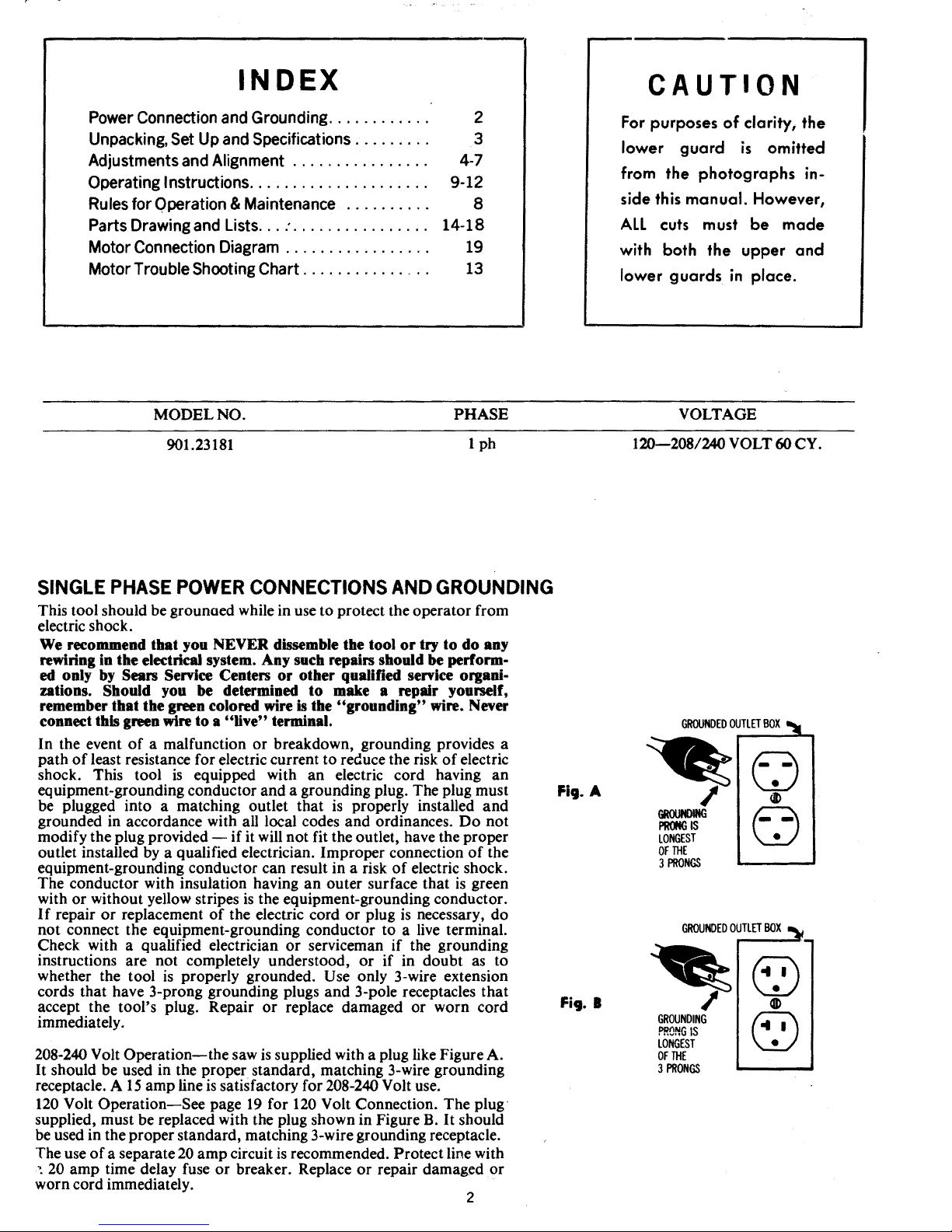
208-240 Volt Operation--the saw is supplied with a plug like Figure A.
It should be used in the proper standard, matching 3-wire grounding
receptacle. A 15 amp line is satisfactory for 208-240 Volt use.
120 Volt Operation--See page 19 for 120 Volt Connection. The plug
supplied, must be replaced with the plug shown in Figure B. It should
be used in the proper standard, matching 3-wire grounding receptacle.
The use of a separate 20 amp circuit is recommended. Protect line with
•. 20 amp time delay fuse or breaker. Replace or repair damaged or
worn cord immediately.
2
Fig. A
GROUNDEDOUTLETBOXI_l
/
GROtINOING
PRONGIS
LONGEST
OFTHE
3PRONGS
©
®
©
GROUNDEDOUTLETBOX
GROUNDING
P,,_NGIS
LONGEST
OFTHE
3PRONGS
©
@
UNPACKING AND SET-UP iNSTRUCTiONS
Your Craftsman Saw has been completely assembled,
tes"_d and table top kerfed at the f'a_ ,'%" and then partially
o,. ;,asembled for packaging and shipment,
We suggest the following procedure:
1, Turn the Elevating Handle at top of column count_'r-
clockwise a few turns to reIease the motor box and re-
move it from under the arm. (Do not discard the ,;_ta[
plate or guard found urrder motor box.)
2, Remove the Arm End Cap but do not disconnect the
,_'_ads to the switch, Insert rolIerhead yoke ar_I motor
a_sembly into the arm. being careful not to damage the
rip pointer on fight side, and rail to extreme back of arm
against column. Lock the entire assembly with the rip
lock, Replace arm cad cap.
3_
4_
Swing arm and position at right angle to guide fence at
0a on miter scale. Locate miter latch in column slot.
Securely lock arm with arm clamp handle.
Place machine on its back (column on floor) and attach
legs wkh four (4) bolts to each leg. Now place machine
in an upright position on its legs. To prevent forward
creeping of the saw carriage, tilt the saw backward by
shimming under the front of table frame or front legs if
so equipped, Use sturdy outrigger supports if any table
extensions are attached to the saw,
AI1electrica[ co_mections have been made for you to operate
your machine on 208 to 240 volts power supply. For change
to I20 volt on single phase models refer to connection dia-
gram on the motor name olate, and page 19 of this manual.
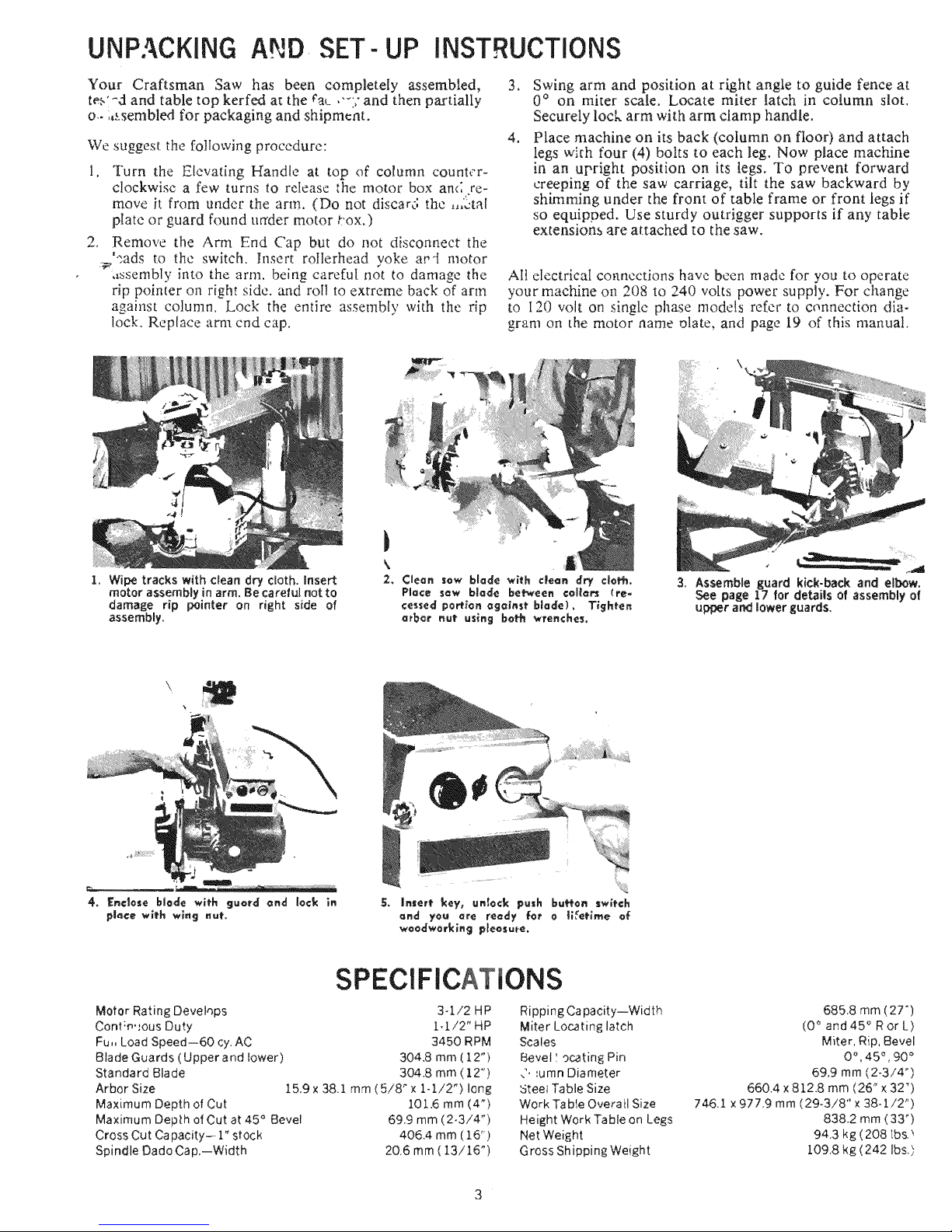
1. Wipe tracks with clean dry cloth, insert
motor assembly in arm. Be careful not to
damage rip pointer on right side of
assemNy.
3. Assemble guard kick-back and elbow.
See page 17 for details of assembly of
upper an_ lower guards.
SPECIFICATIONS
Motor Rating Devehps 3-1/2 HP
Cont;m,,ous Duty 1_.1./2" HP
Fu,, Load Speed--60 cy. AC 3450 RPM
Blade Guards (Upper and lower) 304.8 mm (12")
Standard Blade 304.8 mm (12")
Arbor Size 15,9 x 38.1 mm ( 5/8" x l- 1/2") long
Maximum Depth of Cut 101.6 mm (4 _)
Maximum Depth of Cut at 45 ° Bevel 69.9 mm (2.3/4 ")
Cross Cut Capacity- 1" stock 405.4 mm (16")
Spindle Dado Cap,--Width 20.6 mm( 13/15 ")
Ripping Capacity--Width
Miter Locating latch
Scales
Bevel I ocating Pin
,'. _umn Diameter
5teel Table Size
Work Table Overall Size
Height Work Table on Legs
Net Weight
Gross Shipping Weight
685,8 rnm (27")
(0 ° and 45 ° Ror L)
Miter, Rip. Bevel
0% 45 _,90 °
69.9 mm (2-3/4")
660.4 x 8t2.8 mm (26 _x 32")
746.1 x 977,9 mm (29-3/8" x 38-1/2")
838.2 mm (33 _)
94.3 kg (208 tbs._
!.09.8 kg (242 Ibs.),
ADJUSTMENTS AND ALIGNMENTS
Adiusfmenf of Scales
Rip Scale
The Rip Scale is located on the right side of the
Radial Arm. When the motor is positioned with
motor arbor toward the column it is called "in rip"
position, and material should be fed from right to left.
When the motor arbor is positioned toward the op-
erator it is called "out rip" and material is fed from
left to right. When "in ripping" width dimensions
are located on the top of the scale and when "out
ripping" on the bottom of the scale by use of the
reference pointers. The pointers are adjustabIe and
must be readjusted only when gauge (thickness) of
blade is changed.
To adjust:
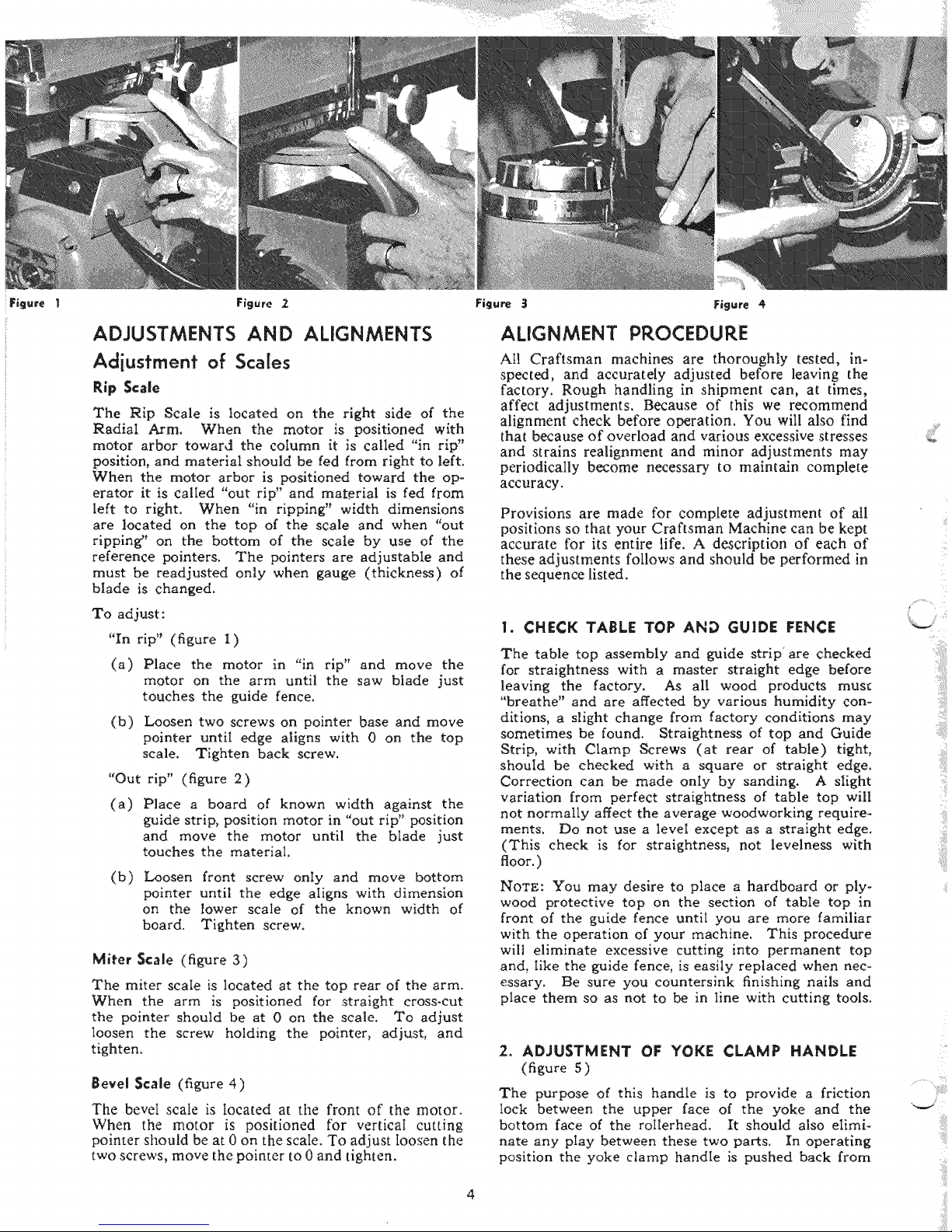
"In rip" (figure I)
(a) Place the motor in "in rip" and move the
motor on the arm until the saw blade just
touches the guide fence.
(b) Loosen two screws on pointer base and move
pointer until edge aligns with 0 on the top
scale. Tighten back screw.
"Out rip" (figure 2)
(a)
Place a board of known width against the
guide strip, position motor in "out rip" position
and move the motor until the blade just
touches the material.
(b) Loosen front screw only and move bottom
pointer until the edge aligns with dimension
on the lower scale of the known width of
board. Tighten screw.
Miter Scale (figure 3)
The miter scale is located at the top rear of the arm.
When the arm is positioned for straight cross-cut
the pointer should be at 0 on the scale. To adjust
loosen the screw holding the pointer, adjust, and
tighten.
Bevel Scale (figure 4)
The bevel scale is Iocated at the front of the motor.
When the motor is positioned for verticaI cutting
pointer should be at 0 on the scale. To adjust Ioosen the
two screws, move the pointer to 0 and tighten.
ALIGNMENT PROCEDURE
Atl Craftsman machines are thoroughly tested, in-
spected,and accurately adjusted before leaving the
factory. Rough handling in shipment can, at times,
affect adjustments. Because of this we recommend
alignment check before operation. You will also find
that because of overload and various excessive stresses
and strains realignment and minor adjustments may
periodically become necessary to maintain complete
accuracy.
Provisions are made for complete adjustment of all
positions so that your Craftsman Machine can be kept
accurate for its entire life. A description of each of
these adjustments follows and should be performed in
the sequence listed.
1. CHECK TABLE TOP AND GUIDE FENCE
The table top assembly and guide strip' are checked
for straightness with a master straight edge before
leaving the factory. As all wood products must
"breathe" and are affected by various humidity con-
ditions, a Might change from factory conditions may
sometimes be found. Straightness of top and Guide
Strip, with Clamp Screws (at rear of table) tight,
should be checked with a square or straight edge.
Correction can be made only by sanding. A slight
variation from perfect straightness of table top will
not normally affect the average woodworking require-
ments. Do not use a leveI except as a straight edge.
(This check is for straightness, not levelness with
floor. )
NOTE: You may desire to place a hardboard or ply-
wood protective top on the section of table top in
front of the guide fence until you are more familiar
with the operation of your machine. This procedure
wilt eliminate excessive cutting into permanent top
and, Iike the guide fence, is easily replaced when nec-
essary. Be sure you countersink finishing nails and
place them so as not to be in line with cutting tools.
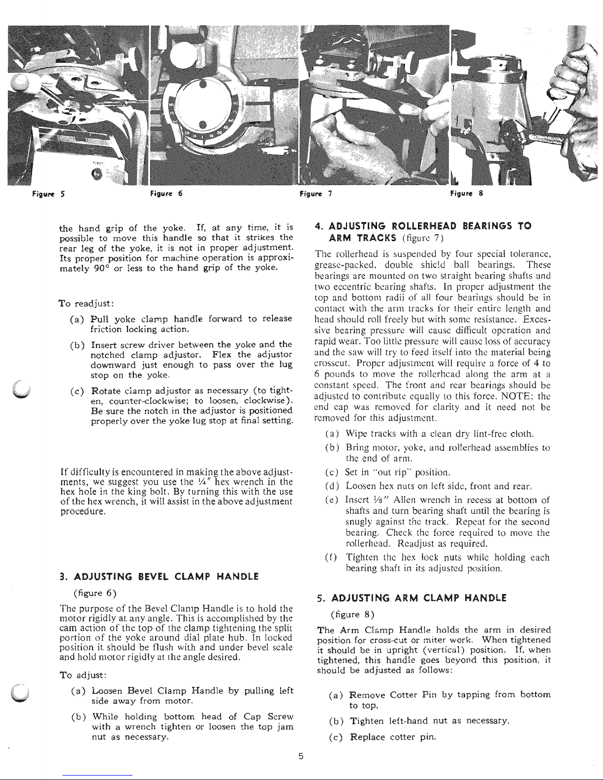
2. ADJUSTMENT OF YOKE CLAMP HANDLE
(figure 5)
The purpose of this handle is to provide a friction
lock between the upper face of the yoke and the
bottom face of the roilerhead. It should also eIiml-
hate any pIay between these two parts. In operating
position the yoke clamp handle is pushed back from
2
i _ :i¸
/
the hand grip of the yoke. If, at any time, it is
possible to move this handle so that it strikes the
rear leg of the yoke, it is not in proper adjustment.
Its proper position for machine operation is approxi-
mately 90 _ or Iess to the hand grip of the yoke.
To readjust :
(a) Pull yoke clamp handle forward to release
friction locking action.
(b)
Insert screw driver between the yoke and the
notched clamp adjustor. FIex the adjustor
downward just enough to pass over the lug
stop on the yoke,
(c)
Notate clamp adjustor as necessary (to tight-
en, counter-clockwise; to loosen, clockwise).
Be sure the notch in the adjustor is positioned
properly over the yoke lug stop at final setting.
If difficulty is encountered in making the above adjust-
ments, we suggest you use the ¼" hex wrench in the
hex hoIe in the king bolt. By turning this with the use
of the hex wrench, it wiIl assist in the above adjustment
procedure.
3. ADJUSTING BEVEL CLAMP HANDLE
(figure 6 )
The purpose of the Bevel Clamp Handle is to hold the
motor rigidly at any angIe, This is accomplished by the
cam action of the top of the clamp tightening the split
portion of the yoke around dial plate hub. In locked
position it should be flush with and under bevel scale
and hold motor rigidly at the angle desired.
To adjust :
(a) Loosen Bevel Clamp Handle by pulling left
side away from motor.
(b) While holding bottom head o[ Cap Screw
with a wrench tighten or Ioosen the top jam
nut as necessary.
4. ADJUSTING ROLLERHEAD BEARINGS TO
ARM TRACKS (figure 7)
The rollerhead is suspended by four speciM tolerance.
grease-packed_ double shic[d bali bearings, These
bearings are mounted on two straight bearing s!mfts and
two eccentric bearing shafts. In proper adjustment the
top and bottom radii of all four bearings should be in
contact with the arm tracks for their entire length and
head shou[d roll freely but with some resistance. Exces-
sive bearing pressure will cause digicult operation and
rapid wear. Too little pressure will cause Ioss of accuracy
and the saw will try to feed itself into the material being
crosscut, Propcr adjustment wilt require a force of 4 to
6 pounds to move the rollerhcad along the arm at a
constant speed, The front and rear bearings should be
adjustcd to contribute equally to this force, NOTE: the
end cap was rcmovcd for clarity and it need not be
removed for this adjustment.
(a) Wipe tracks with a clean dry lint-free ctoth.
(b) Bring motor, yoke, and rolIerhead assemblies to
the end of arm.
(c) Set in _'out rip" position.
(d) Loosen hex nuts on left side, front and rear,
(e) Insert 1is" Alien wrench in recess at bottom of
shafts and turn bearing shaft until the bearing is
snugly against the track. Repeat for the second
bearing, Check the force required to move the
roIlerhead. Readjust as required,
(f) Tighten the hex lock nuts white hoIding each
bearing shaft in its adjusted positiom
5. ADJUSTING ARM CLAMP HANDLE
(figure 8)
The Arm Clamp Handle holds the arm in desired
position for cross-cut or miter work. When tightened
it should be in upright (vertical) position. If, when
tightened, this handle goes beyond this position, it
should be adjusted as follows:
(a) Remove Cotter Pin by tapping from bottom
to top.
(b) Tighten left-hand nut as necessary.
(e) Replace cotter pin.
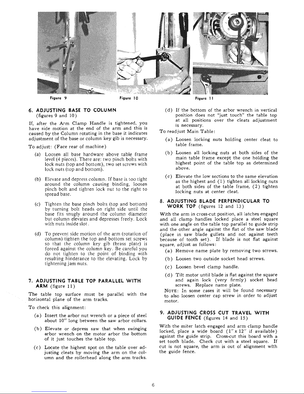
6. ADJUSTING BASE TO COLUMN
(figures 9 and 10)
If, after the Arm CIamp Handle is tightened, you
have side motion at the end of the arm and this is
caused by the Column rotating in the base it indicates
adjustment of the base or column key glb is necessary.
To adjust: (Face rear of machine)
(a)
Loosen all base hardware above table frame
level (4 pieces). There are: two pinch bolts with
lock nuts (top and bottom), two set screws with
lock nuts (top and bottom).
(b) Elevate and depress column. If base is too tight
around the column causing binding, loosen
pinch bolt and tighten lock nut to the right to
spread base.
(c) Tighten the base pinch bolts (top and bottom)
by turning bolt heads on right side until the
base fits snugly around the column diameter
but column elevates and depresses freely. Lock
with nuts inside slot.
(d) To prevent side motion of the arm (rotation of
column) tighten the top and bottom set screws
so that the coIumn key gib (brass plate) is
forced against the column key. Be careful you
do not tighten to the point of binding with
resulting hinderance to the elevating. Lock by
tightening jam nuts.
7. ADJUSTING TABLE TOP PARALLEL WITH
ARM (figure 11)
The table top surface must be parallel with the
horizontal ptane of the arm tracks.
To check this alignment:
(a) Insert the arbor nut wrench or a piece of steel
about 10" long between the saw arbor collars.
(b) Elevate or depress saw that when swinging
arbor wrench on the motor arbor the bottom
of it just touches the table top.
(c) Locate the highest spot on the table over ad-
justing cleats by moving the arm on the col-
umn and the rolierhead along the arm tracks.
(d) If the bottom of the arbor wrench in vertical
position does not "just touch" the table top
at all positions over the cleats adjustment
is necessary.
To readjust Main Table:
(a) Loosen Iocking nuts holding center cleat to
table frame.
(b)
(c)
Loosen all locking nuts at both sides of the
main table frame except the one holdin_ the
highest point of the table top as determined
above,
Elevate the low sections to the same elevation
as the highest and (1) tighten all locking nuts
at both sides of the table frame, (2) tighten
locking nuts at center cleat.
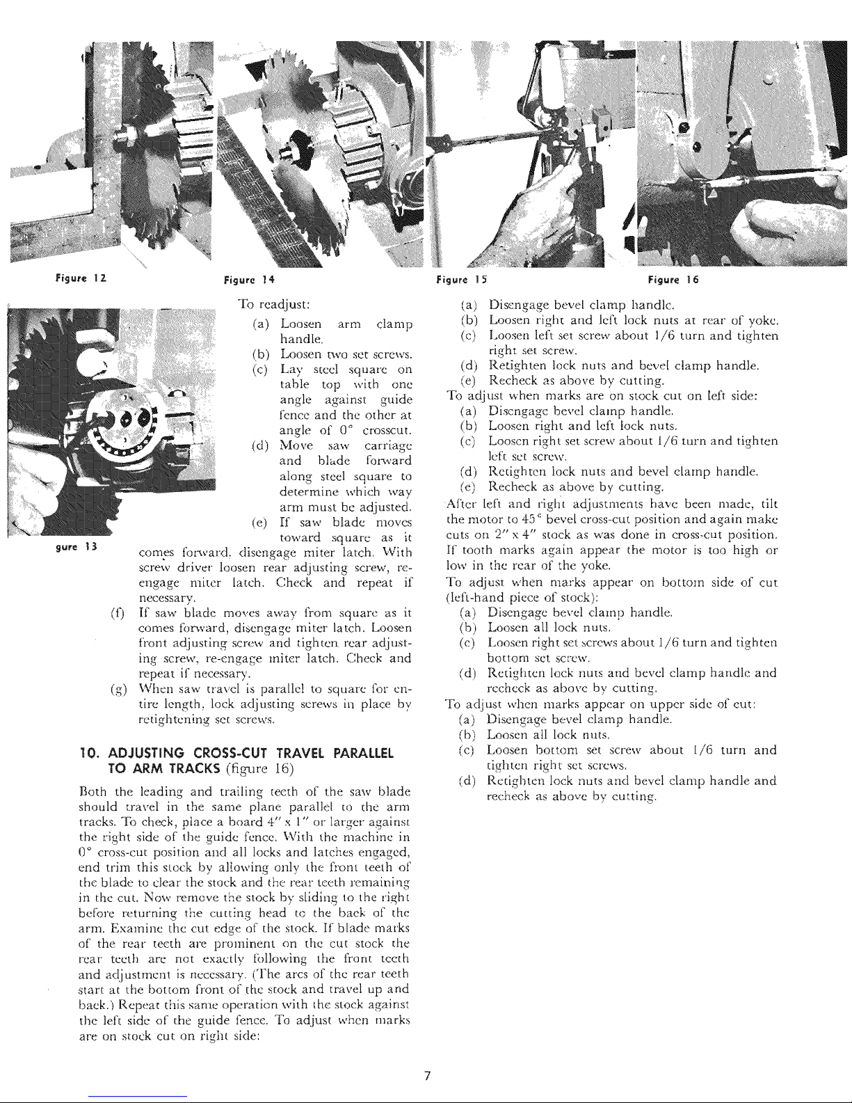
8. ADJUSTING BLADE PERPENDICULAR TO
WORK TOP (figures 12 and 13)
With the arm in cross-cut position, all latches engaged
and alI clamp handles locked place a steeI square
with one angle on the tabIe top parallel to guide strip
and the other angle against the flat of the saw blade
(place in saw blade gullets and not against teeth
because of tooth set). If blade is not flat against
squarej adjust as follows:
(a) Remove name plate by removing two screws.
(b) Loosen two outside socket head screws.
(c) Loosen bevel clamp handle.
(d) Tilt motor until blade is flat against the square
and again lock (very firmly) socket head
screws. Replace name plate,
NOTE: In some cases it will be found necessary
to also Ioosen center cap screw in order to adjust
motor.
9. ADJUSTING CROSS CUT TRAVEL WITH
GUIDE FENCE (figures 14 and 15)
With the miter latch engaged and arm clamp handle
locked, place a wide board (l"x 12" if available)
against the guide strip. Cross-cut this board with a
set tooth blade. Check cut with a steel square_ If
cut is not square, the arm is out of alignment with
the guide fence.
IO
(g)
To readjust:
(a) Loosen arm clamp
handle.
(b) Loosen two set screws.
(c) Lay steel square on
table top with one
angle against guide
fence and the other at
angle of 0 ° crosscut.
(d) Move saw carriage
and blade forward
along steel square to
determine which way
arm must be adjusted.
(e) [f saw blade moves
toward square as it
comes foc_vard, disengage miter latch. With
screw driver loosen rear adjusting screw, re-
engage miter latch. Check and repeat if
necessary.
If saw blade moves away from square as it
comes forward, disengage miter latch. Loosen
front adjusting screw and dghten rear adjust-
ing screw, re-engage miter latch. Check and
repeat if necessa W.
When saw travel ix paralle! to square for en-
tire length, lock adjusting screws in place by
retightcning set screws.
10. ADJUSTING CROSS-CUT TRAVEL PARALLEL
TO ARM TRACKS (fig-ure I6)
Both the leading and trailing teeth of the saw blade
should travel in the same plane parallel to the arm
tracks. To check, place a board 4" x 1" or larger against
the right side of the guide fence. With the machine in
0 ° cross-cut position and all locks and latches engaged,
end trim this stock by allowing only the front teeth of
the blade to clear the stock and the rear teeth remaining
in thc cut. Now remove the stock by s[idlng to the right
before returning the cutting head to the baek of the
arm. Examine the cut edge of the stock. If blade marks
of' the rear teeth are prominent on the cut stock d_e
rear teeth are not exactly following the front teeth
and adjustment is necessary. (The arcs of the rear teeth
start at the bottom front o[' the stock and travel up and
baek.} Repea_ this same operation whh the stock against
the left side of the guide fence. _l)J adjust when marks
are on stock cut on right side:
Sure _ 3
(a) Disengage bevel clamp handle,
(b) Loosen right attd left lock nuts at rear of yoke,
(c) Loosen left set screw about 1/6 turn and tighten
right set screw,
(d) Ret,ighten lock nuts and bevel damp handle.
(e) Recheck as above by cutting,
To adjust when marks are on stock cut on [eft side:
(a) Discngagc bevel clamp handle.
(b) Loosen right and left fock nuts,
(c) Looscn right set screw about 1/6 turn and tighten
left set screw,
(d) Retighten lock nuts and bevel damp handle.
(e) Recheck as above by cutting,
After left and rlght adjustments have been made, tilt
the motor to 45 _ bevel cross-cut position and again make
cuts on 2"x 4" stock as was done in cross-cut position.
If tooth marks again appear the motor is too high or
low in the rear of the yoke.
To adjust when marks appear on bottom side of cut
(left-hand piece of stock):
Disengage bevel clamp handle.
(b) Loosen all lock nuts,
(c) Loosen right set screws about i/6 turn and tighten
bottom set screw,
(d) Redghten lock nuts and bevel clamp handle and
recheck as above by cutting.
To adjust when marks appear on upper side of cut:
(a) Disengage Bevel clamp handle,
(b) Loosen all lock nuts.
(c) Loosen bottom set screw about l/6 turn and
tighten right set screws.
(d) Retighten lock nuts and bevel clamp handle and
recheck as above by cutting,
 Loading...