

Craftsman 900277303 Owner’s Manual

Operator's Manual
CRAFrSMAN
PLATE JOINER
Model No.
900.277303
CAUTION: Read and follow all
Safety Rules and Operating
Instructions before First Use
of this Product
Sears, Roebuck and Co., Hoffman Estates, IL 60179 USA
Form No 631088-00 AUG05
• Safety
• Operation
• Maintenance
• Parts List
• Espahol pg. 14
ONEYEAR FULL WARRANTY ON CRAFTSMAN PROFESSIONAL TOOL
If this Craftsman Professional tool fails to give complete satisfaction within one
year from the date of purchase, RETURN IT TO ANY SEARS STORE OR PARTS
& REPAIR CENTER OR OTHER CRAFTSMAN OUTLET IN THE UNITED STATES
FOR FREE REPAIR.
This warranty gives you specific legal rights, and you may also have other rights
which vary from state to state.
Sears, Roebuck and Co., Dept. 817WA, Hoffman Estates, IL 60179
IMPORTANT SAFETY
INSTRUCTIONS
AWARNING: When using electric tools,
basic safety precautions should always be
followed to reduce risk of fire, electric
shock, and personal injury, including the
following:
READ ALL
INSTRUCTIONS
DOUBLE INSULATION
Double insulated tools are constructed
throughout with two separate layers of
electrical insulation or one double thickness
of insulation between you and the tool's
electrical system. Tools built with this
insulation system are not intended to be
grounded. As a result, your tool is equipped
with a two prong plug which permits you to
use extension cords without concern for
maintaining a ground connection.
NOTE: Double insulation does not take
the place of normal safety precautions
when operating this tool. The insulation
system is for added protection against
injury resulting from a possible electrical
insulation failure within the tool.
ACAUTION: WHEN SERVICING USE
ONLY IDENTICAL REPLACEMENT
PARTS. Repair or replace damaged cords.
POLARIZED PLUGS
Polarized plugs (one blade is wider than
the other) are used on equipment to
reduce the risk of electric shock. When
provided, this plug will fit into a polarized
outlet only one way. If the plug does not fit
fully into the outlet, reverse the plug. If it
still does not fit, contact a qualified
electrician to install the proper outlet. Do
not change the plug in any way.
• KEEP WORK AREA CLEAN. Cluttered
areas and benches invite injuries.
• CONSIDER WORKAREA ENVIRON-
MENT. Don't expose power tools to rain.
Don't use power tools in damp or wet
locations. Keep work area well lit. Do not
use tool in presence of flammable liquids
or gases.
• GUARD AGAINST ELECTRIC SHOCK.
Prevent body contact with grounded
surfaces. For example; pipes, radiators,
ranges, and refrigerator enclosures.
• KEEP CHILDREN AWAY. Do not let
visitors contact tool or extension cord. All
visitors should be kept away from work
area.
• STORE IDLE TOOLS. When not in use,
tools should be stored in dry, and high or
locked-up place - out of reach of
children.
• DON'T FORCE TOOL. It will do the job
better and safer at the rate for which it
was intended.
• USE RIGHT TOOL. Don't force small
tool or attachment to do the job of a
heavy-duty tool. Don't use tool for
purpose not intended.
• DRESS PROPERLY. Do not wear loose
clothing or jewelry. They can be caught
in moving parts. Rubber gloves and non-
skid footwear are recommended when
working outdoors. Wear protective hair
covering to contain long hair. Air vents
often cover moving parts and should
also be avoided.
• USE SAFETY GLASSES. Also use face
or dust mask if operation is dusty.
• DON'T ABUSE CORD. Never carry tool
by cord or yank it to disconnect from
receptacle. Keep cord from heat, oil, and
sharp edges.
• SECUREWORK.Useclampsora
visetoholdworkIt'ssaferthanusing
yourhandanditfreesbothhandsto
operatetool
• DON'TOVERREACH.Keepproper
footingandbalanceatalltimes
• MAINTAINTOOLSWITHCARE.Keep
toolssharpandcleanforbetterand
saferperformanceFollowinstructions
forlubricatingandchangingaccessories
Inspecttoolcordsperiodicallyandif
damaged,haverepairedbyauthorized
servicefacilityInspectextensioncords
periodicallyandreplaceifdamaged
Keephandlesdry,clean,andfreefrom
oilandgrease
• DISCONNECTORLOCKOFFTOOLS
whennotinuse,beforeservicing,and
whenchangingaccessories,suchas
blades,bits,cutters
• REMOVEADJUSTINGKEYSAND
WRENCHES.Formhabitofchecking
toseethatkeysandadjusting
wrenchesareremovedfromtool
beforeturningiton
• AVOIDUNINTENTIONALSTARTING.
Don'tcarrytoolwithfingeronswitchBe
sureswitchisoffwhenpluggingin
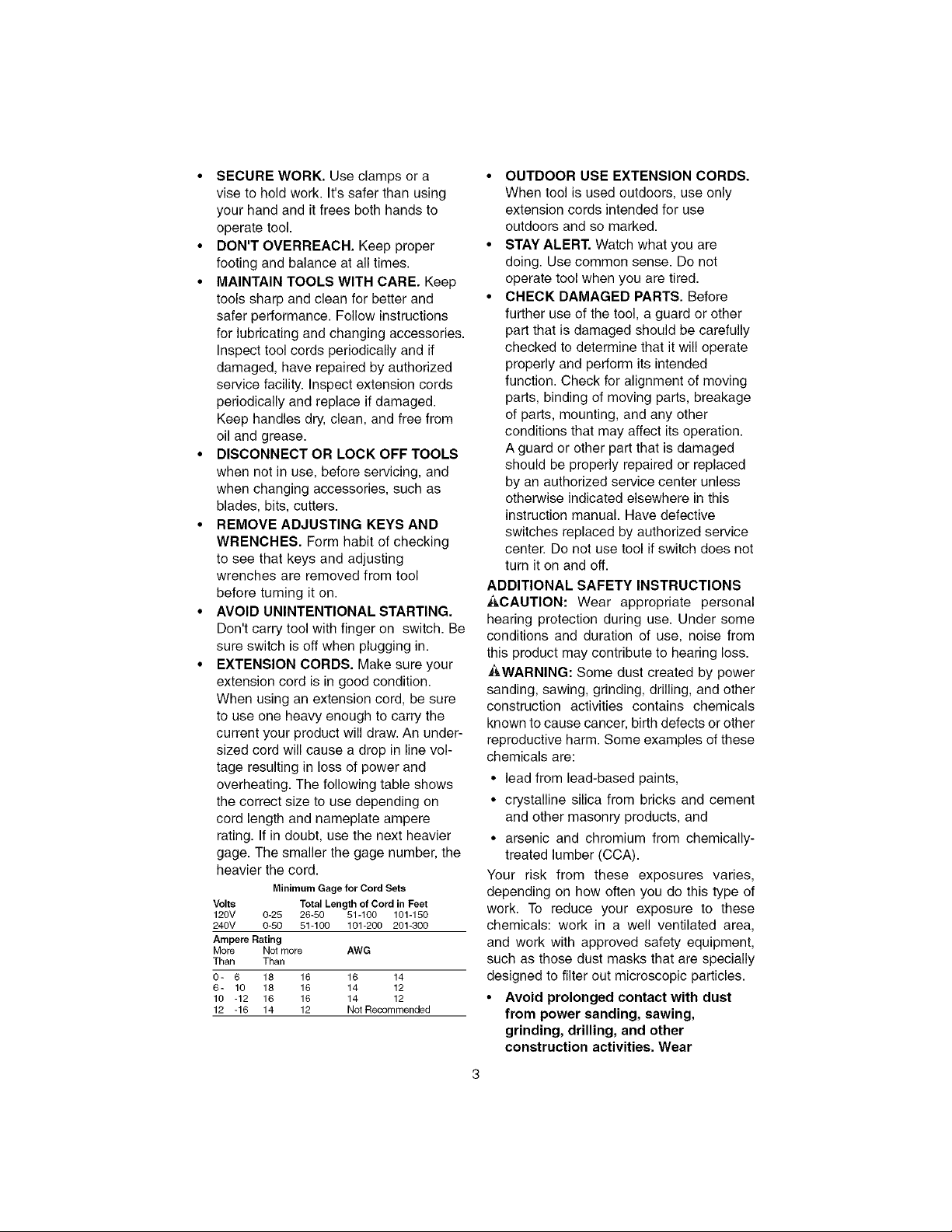
• EXTENSIONCORDS.Makesureyour
extensioncordisingoodcondition
Whenusinganextensioncord,besure
touseoneheavyenoughtocarrythe
currentyourproductwilldrawAnunder-
sizedcordwillcauseadropinlinevol-
tageresultinginlossofpowerand
overheatingThefollowingtableshows
thecorrectsizetousedependingon
cordlengthandnameplateampere
ratingIfindoubt,usethenextheavier
gageThesmallerthegagenumber,the
heavierthecord
Minimum Gage for Cord Sets
Volts Total Length of Cord in Feet
120V 0-25 26-50 51-100 101-150
240V 0-50 51-100 101-200 201-300
Ampere Rating
More Not more AWG
Than Than
0- 6 18 16 16 14
6- 10 18 16 14 12
10 -12 16 16 14 12
12 -16 14 12 Not Recommended
• OUTDOOR USE EXTENSION CORDS.
When tool is used outdoors, use only
extension cords intended for use
outdoors and so marked
• STAY ALERT. Watch what you are
doing Use common sense Do not
operate tool when you are tired
• CHECK DAMAGED PARTS. Before
further use of the tool, a guard or other
part that is damaged should be carefully
checked to determine that it will operate
properly and perform its intended
function Check for alignment of moving
parts, binding of moving parts, breakage
of parts, mounting, and any other
conditions that may affect its operation
A guard or other part that is damaged
should be properly repaired or replaced
by an authorized service center unless
otherwise indicated elsewhere in this
instruction manual Have defective
switches replaced by authorized service
center Do not use tool if switch does not
turn it on and off
ADDITIONAL SAFETY INSTRUCTIONS
_,CAUTION: Wear appropriate personal
hearing protection during use Under some
conditions and duration of use, noise from
this product may contribute to hearing loss
_WARNING: Some dust created by power
sanding, sawing, grinding, drilling, and other
construction activities contains chemicals
known to cause cancer, birth defects or other
reproductive harm Some examples of these
chemicals are:
• lead from lead-based paints,
• crystalline silica from bricks and cement
and other masonry products, and
• arsenic and chromium from chemically-
treated lumber (CCA)
Your risk from these exposures varies,
depending on how often you do this type of
work To reduce your exposure to these
chemicals: work in a well ventilated area,
and work with approved safety equipment,
such as those dust masks that are specially
designed to filter out microscopic particles
• Avoid prolonged contact with dust
from power sanding, sawing,
grinding, drilling, and other
construction activities. Wear
protective clothing and wash
exposed areas with soap and water.
Allowing dust to get into your mouth,
eyes, or lay on the skin may promote
absorption of harmful chemicals.
_WARNING: Use of this tool can generate
and/or disburse dust, which may cause
serious and permanent respiratory or other
injury. Always use NIOSH/OSHA approved
respiratory protection appropriate for the
dust exposure. Direct particles away from
face and body.
SAVE THESE
INSTRUCTIONS
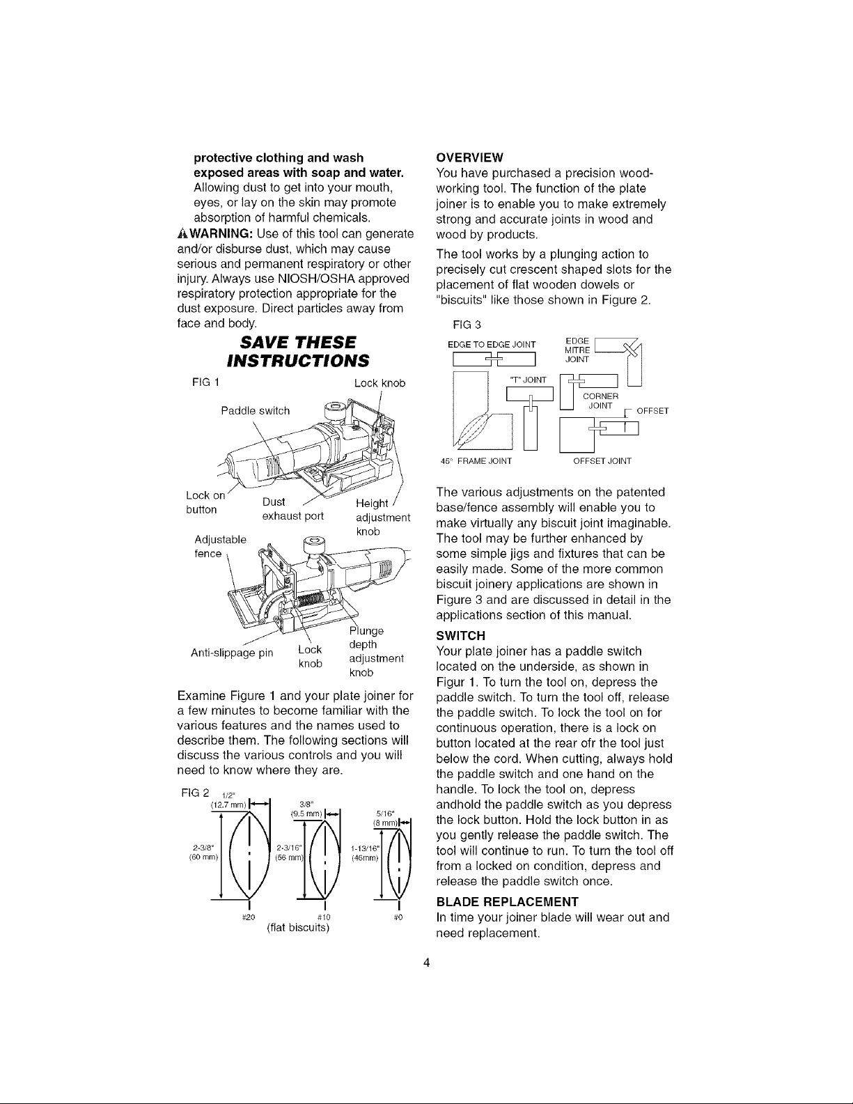
FIG 1 Lock knob
Paddle switch
\
OVERVIEW
You have purchased a precision wood-
working tool. The function of the plate
joiner is to enable you to make extremely
strong and accurate joints in wood and
wood by products.
The tool works by a plunging action to
precisely cut crescent shaped slots for the
placement of flat wooden dowels or
"biscuits" like those shown in Figure 2.
FIG3
EDGE TO EDGE JOINT EDGE [_A
__ _ OFFSET
45' FRAME JOINT OFFSET JOINT
Lock on
button
Adjustable
fence _
Anti-slippage pin Lock
Dust Height
exhaust port adjustment
knob
knob
Plunge
depth
adjustment
knob
Examine Figure 1 and your plate joiner for
a few minutes to become familiar with the
various features and the names used to
describe them. The following sections will
discuss the various controls and you will
need to know where they are.
FIG2 1/2.
3/8"
(9.5 mm)_ 5/16'
2-3/8" 2-3/16" 1-13/16"
(60 mm) (56 m_)_ (48mm6)"1 _
I I I
#20 #10 #0
(flat biscuits)
The various adjustments on the patented
base/fence assembly will enable you to
make virtually any biscuit joint imaginable.
The tool may be further enhanced by
some simple jigs and fixtures that can be
easily made. Some of the more common
biscuit joinery applications are shown in
Figure 3 and are discussed in detail in the
applications section of this manual.
SWITCH
Your plate joiner has a paddle switch
located on the underside, as shown in
Figur 1. To turn the tool on, depress the
paddle switch. To turn the tool off, release
the paddle switch. To lock the tool on for
continuous operation, there is a lock on
button located at the rear ofr the tool just
below the cord. When cutting, always hold
the paddle switch and one hand on the
handle. To lock the tool on, depress
andhold the paddle switch as you depress
the lock button. Hold the lock button in as
you gently release the paddle switch. The
tool will continue to run. To turn the tool off
from a locked on condition, depress and
release the paddle switch once.
BLADE REPLACEMENT
In time your joiner blade will wear out and
need replacement.
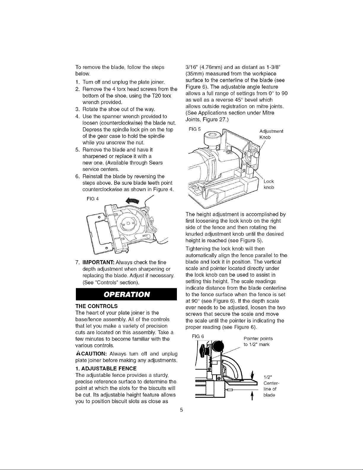
Toremovetheblade,followthesteps
below.
1.Turnoffandunplugtheplatejoiner.
2.Removethe4torxheadscrewsfromthe
bottomoftheshoe,usingtheT20torx
wrenchprovided.
3.Rotatetheshoeoutoftheway.
4.Usethespannerwrenchprovidedto
loosen(counterclockwise)thebladenut.
Depressthespindlelockpinonthetop
ofthegearcasetoholdthespindle
whileyouunscrewthenut.
5.Removethebladeandhaveit
sharpenedorreplaceitwitha
newone.(AvailablethroughSears
servicecenters.
6.Reinstallthebladebyreversingthe
stepsabove.Besurebladeteethpoint
counterclockwiseasshowninFigure4.
F,G4
7. IMPORTANT: Always check the fine
depth adjustment when sharpening or
replacing the blade. Adjust if necessary.
(See "Controls" section).
THE CONTROLS
The heart of your plate joiner is the
base/fence assembly. All of the controls
that let you make a variety of precision
cuts are located on this assembly. Take a
few minutes to become familiar with the
various controls.
ACAUTION: Always turn off and unplug
plate joiner before making any adjustments.
1. ADJUSTABLE FENCE
The adjustable fence provides a sturdy,
precise reference surface to determine the
point at which the slots for the biscuits will
be cut. Its adjustable height feature allows
you to position biscuit slots as close as
3/16" (4.76mm) and as distant as 1-3/8"
(35ram) measured from the workpiece
surface to the centerline of the blade (see
Figure 6). The adjustable angle feature
allows a full range of settings from 0° to 90
as well as a reverse 45° bevel which
allows outside registration on mitre joints.
(See Applications section under Mitre
Joints, Figure 27.)
FIG 5
The height adjustment is accomplished by
first loosening the lock knob on the right
side of the fence and then rotating the
knurled adjustment knob until the desired
height is reached (see Figure 5).
Tightening the lock knob will then
automatically align the fence parallel to the
blade and lock it in position. The vertical
scale and pointer located directly under
the lock knob can be used to assist in
setting this height. The scale readings
indicate distance from the blade centerline
to the fence surface when the fence is set
at 90° (see Figure 6). Ifthe depth scale
ever needs to be adjusted, loosen the two
screws that secure the scale and move
the scale until the pointer is indicating the
proper reading (see Figure 6).
FIG6 Pointerpoints
Adjustment
Knob
knob
to 1/2" mark
1/2"
line of
Center-
_. blade
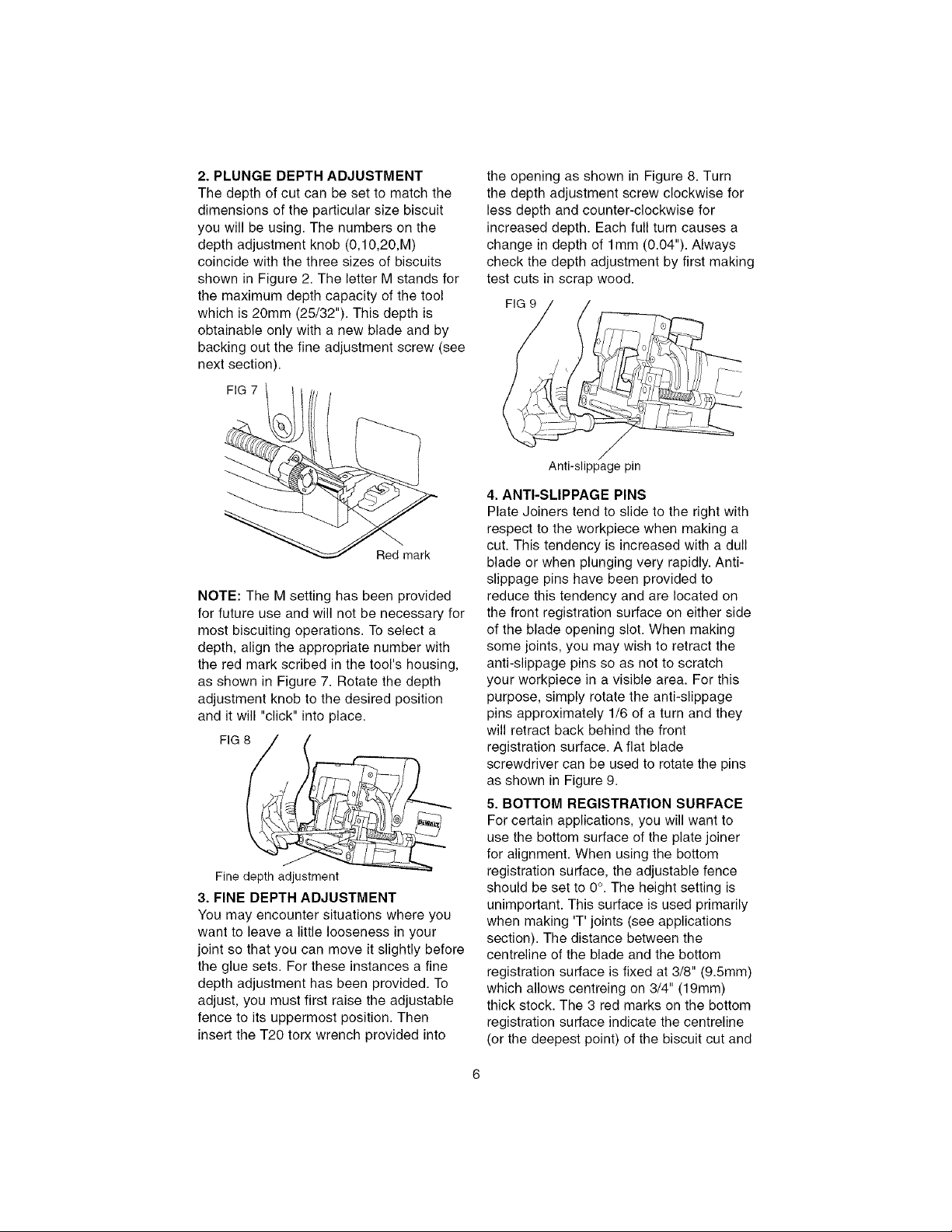
2. PLUNGE DEPTH ADJUSTMENT
The depth of cut can be set to match the
dimensions of the particular size biscuit
you will be using. The numbers on the
depth adjustment knob (0,10,20,M)
coincide with the three sizes of biscuits
shown in Figure 2. The letter M stands for
the maximum depth capacity of the tool
which is 20ram (25/32"). This depth is
obtainable only with a new blade and by
backing out the fine adjustment screw (see
next section).
F' 7\/
Red mark
NOTE: The M setting has been provided
for future use and will not be necessary for
most biscuiting operations. To select a
depth, align the appropriate number with
the red mark scribed in the tool's housing,
as shown in Figure 7. Rotate the depth
adjustment knob to the desired position
and it will "click" into place.
FIG
Fine depth adjustment
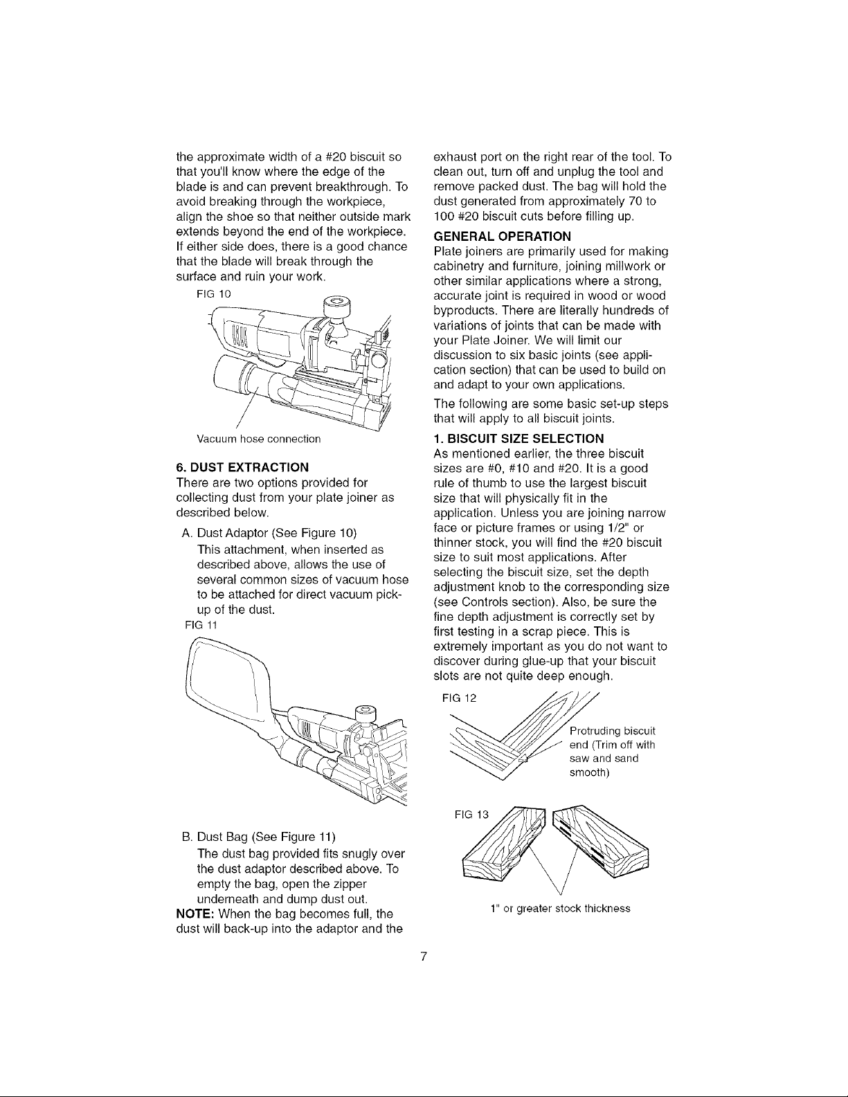
3. FINE DEPTH ADJUSTMENT
You may encounter situations where you
want to leave a little looseness in your
joint so that you can move it slightly before
the glue sets. For these instances a fine
depth adjustment has been provided. To
adjust, you must first raise the adjustable
fence to its uppermost position. Then
insert the T20 torx wrench provided into
the opening as shown in Figure 8. Turn
the depth adjustment screw clockwise for
less depth and counter-clockwise for
increased depth. Each full turn causes a
change in depth of lmm (0.04"). Always
check the depth adjustment by first making
test cuts in scrap wood.
FIG9
/
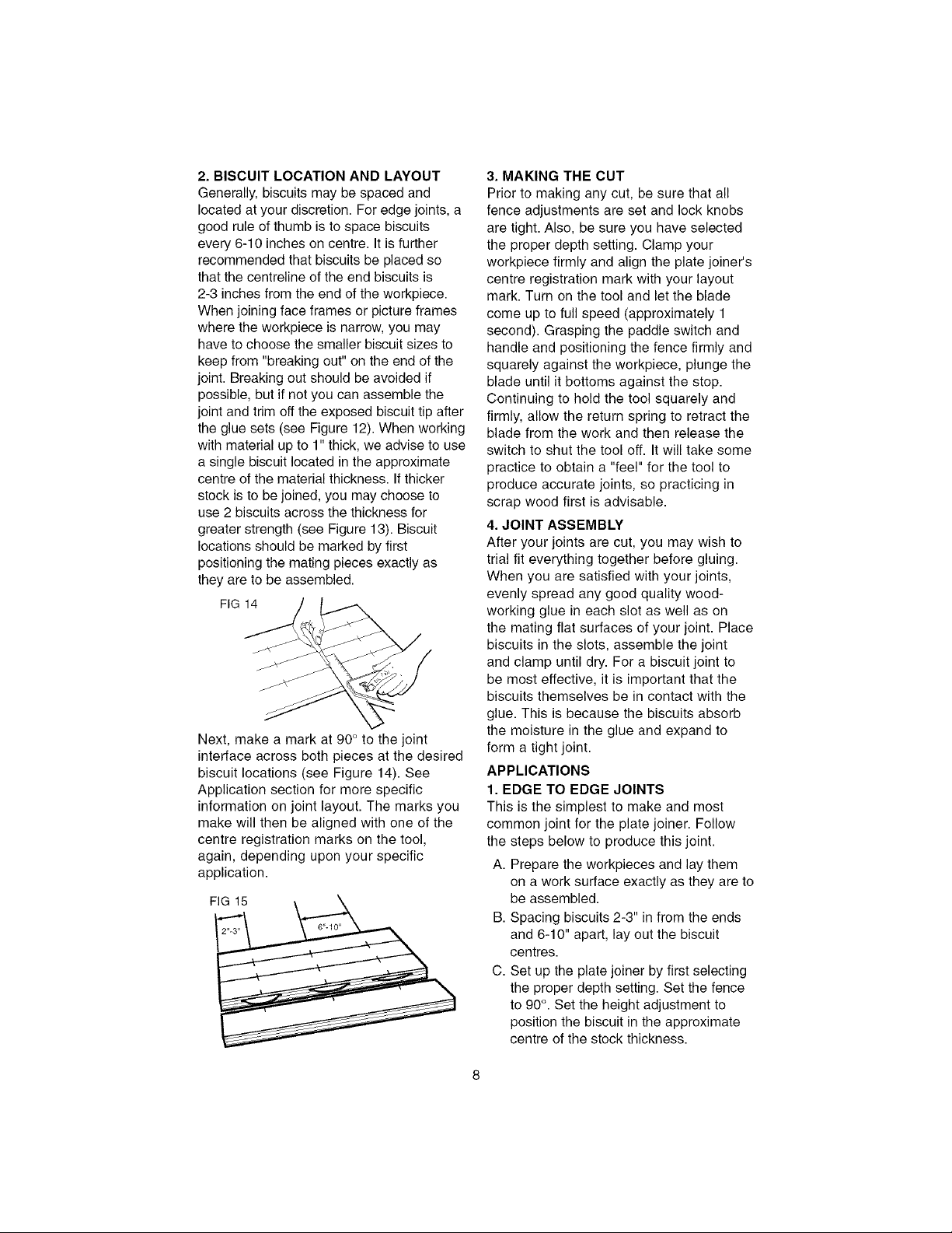
Antkslippage pin
4. ANTI-SLIPPAGE PINS
Plate Joiners tend to slide to the right with
respect to the workpiece when making a
cut. This tendency is increased with a dull
blade or when plunging very rapidly. Anti-
slippage pins have been provided to
reduce this tendency and are located on
the front registration surface on either side
of the blade opening slot. When making
some joints, you may wish to retract the
anti-slippage pins so as not to scratch
your workpiece in a visible area. For this
purpose, simply rotate the anti-slippage
pins approximately 1/6 of a turn and they
will retract back behind the front
registration surface. A flat blade
screwdriver can be used to rotate the pins
as shown in Figure 9.
5. BOTTOM REGISTRATION SURFACE
For certain applications, you will want to
use the bottom surface of the plate joiner
for alignment. When using the bottom
registration surface, the adjustable fence
should be set to 0°. The height setting is
unimportant. This surface is used primarily
when making 'T' joints (see applications
section). The distance between the
centreline of the blade and the bottom
registration surface is fixed at 3/8" (9.5ram)
which allows centreing on 3/4" (19mm)
thick stock. The 3 red marks on the bottom
registration surface indicate the centreline
(or the deepest point) of the biscuit cut and
theapproximatewidthofa#20biscuitso
thatyou'llknowwheretheedgeofthe
bladeisandcanpreventbreakthrough.To
avoidbreakingthroughtheworkpiece,
aligntheshoesothatneitheroutsidemark
extendsbeyondtheendoftheworkpiece.
Ifeithersidedoes,thereisagoodchance
thatthebladewillbreakthroughthe
surfaceandruinyourwork.
FIG10
Vacuum hose connection
6. DUST EXTRACTION
There are two options provided for
collecting dust from your plate joiner as
described below.
A. Dust Adaptor (See Figure 10)
This attachment, when inserted as
described above, allows the use of
several common sizes of vacuum hose
to be attached for direct vacuum pick-
up of the dust.
FIG 11
exhaust port on the right rear of the tool. To
clean out, turn off and unplug the tool and
remove packed dust. The bag will hold the
dust generated from approximately 70 to
100 #20 biscuit cuts before filling up.
GENERAL OPERATION
Plate joiners are primarily used for making
cabinetry and furniture, joining millwork or
other similar applications where a strong,
accurate joint is required in wood or wood
byproducts. There are literally hundreds of
variations of joints that can be made with
your Plate Joiner. We will limit our
discussion to six basic joints (see appli-
cation section) that can be used to build on
and adapt to your own applications.
The following are some basic set-up steps
that will apply to all biscuit joints.
1. BISCUIT SIZE SELECTION
As mentioned earlier, the three biscuit
sizes are #0, #10 and #20. It is a good
rule of thumb to use the largest biscuit
size that will physically fit in the
application. Unless you are joining narrow
face or picture frames or using 1/2" or
thinner stock, you will find the #20 biscuit
size to suit most applications. After
selecting the biscuit size, set the depth
adjustment knob to the corresponding size
(see Controls section). Also, be sure the
fine depth adjustment is correctly set by
first testing in a scrap piece. This is
extremely important as you do not want to
discover during glue-up that your biscuit
slots are not quite deep enough.
FIG 12
B. Dust Bag (See Figure 11)
The dust bag provided fits snugly over
the dust adaptor described above. To
empty the bag, open the zipper
underneath and dump dust out.
NOTE: When the bag becomes full, the
dust will back-up into the adaptor and the
3rotruding biscuit
end (Trim off with
saw and sand
smooth)
1" or greater stock thickness
2.BISCUITLOCATIONANDLAYOUT
Generally,biscuitsmaybespacedand
locatedatyourdiscretion.Foredgejoints,a
goodruleofthumbistospacebiscuits
every6-10inchesoncentre.Itisfurther
recommendedthatbiscuitsbeplacedso
thatthecentrelineoftheendbiscuitsis
2-3inchesfromtheendoftheworkpiece.
Whenjoiningfaceframesorpictureframes
wheretheworkpieceisnarrow,youmay
havetochoosethesmallerbiscuitsizesto
keepfrom"breakingout"ontheendofthe
joint.Breakingoutshouldbeavoidedif
possible,butifnotyoucanassemblethe
jointandtrimofftheexposedbiscuittipafter
thegluesets(seeFigure12).Whenworking
withmaterialupto1"thick,weadvisetouse
asinglebiscuitlocatedintheapproximate
centreofthematerialthickness.Ifthicker
stockistobejoined,youmaychooseto
use2biscuitsacrossthethicknessfor
greaterstrength(seeFigure13).Biscuit
locationsshouldbemarkedbyfirst
positioningthematingpiecesexactlyas
theyaretobeassembled.
FIG14
Next,makeamarkat90°tothejoint
interfaceacrossbothpiecesatthedesired
biscuitlocations(seeFigure14).See
Applicationsectionformorespecific
informationonjointlayout.Themarksyou
makewillthenbealignedwithoneofthe
centreregistrationmarksonthetool,
again,dependinguponyourspecific
application.
FIG 15
3. MAKING THE CUT
Prior to making any cut, be sure that all
fence adjustments are set and lock knobs
are tight. Also, be sure you have selected
the proper depth setting. Clamp your
workpiece firmly and align the plate joiner's
centre registration mark with your layout
mark. Turn on the tool and let the blade
come up to full speed (approximately 1
second). Grasping the paddle switch and
handle and positioning the fence firmly and
squarely against the workpiece, plunge the
blade until it bottoms against the stop.
Continuing to hold the tool squarely and
firmly, allow the return spring to retract the
blade from the work and then release the
switch to shut the tool off. It will take some
practice to obtain a "feel" for the tool to
produce accurate joints, so practicing in
scrap wood first is advisable.
4. JOINT ASSEMBLY
After your joints are cut, you may wish to
trial fit everything together before gluing.
When you are satisfied with your joints,
evenly spread any good quality wood-
working glue in each slot as well as on
the mating flat surfaces of your joint. Place
biscuits in the slots, assemble the joint
and clamp until dry. For a biscuit joint to
be most effective, it is important that the
biscuits themselves be in contact with the
glue. This is because the biscuits absorb
the moisture in the glue and expand to
form a tight joint.
APPLICATIONS
1. EDGE TO EDGE JOINTS
This is the simplest to make and most
common joint for the plate joiner. Follow
the steps below to produce this joint.
A. Prepare the workpieces and lay them
on a work surface exactly as they are to
be assembled.
B. Spacing biscuits 2-3" in from the ends
and 6-10" apart, lay out the biscuit
centres.
C. Set up the plate joiner by first selecting
the proper depth setting. Set the fence
to 90°. Set the height adjustment to
position the biscuit in the approximate
centre of the stock thickness.
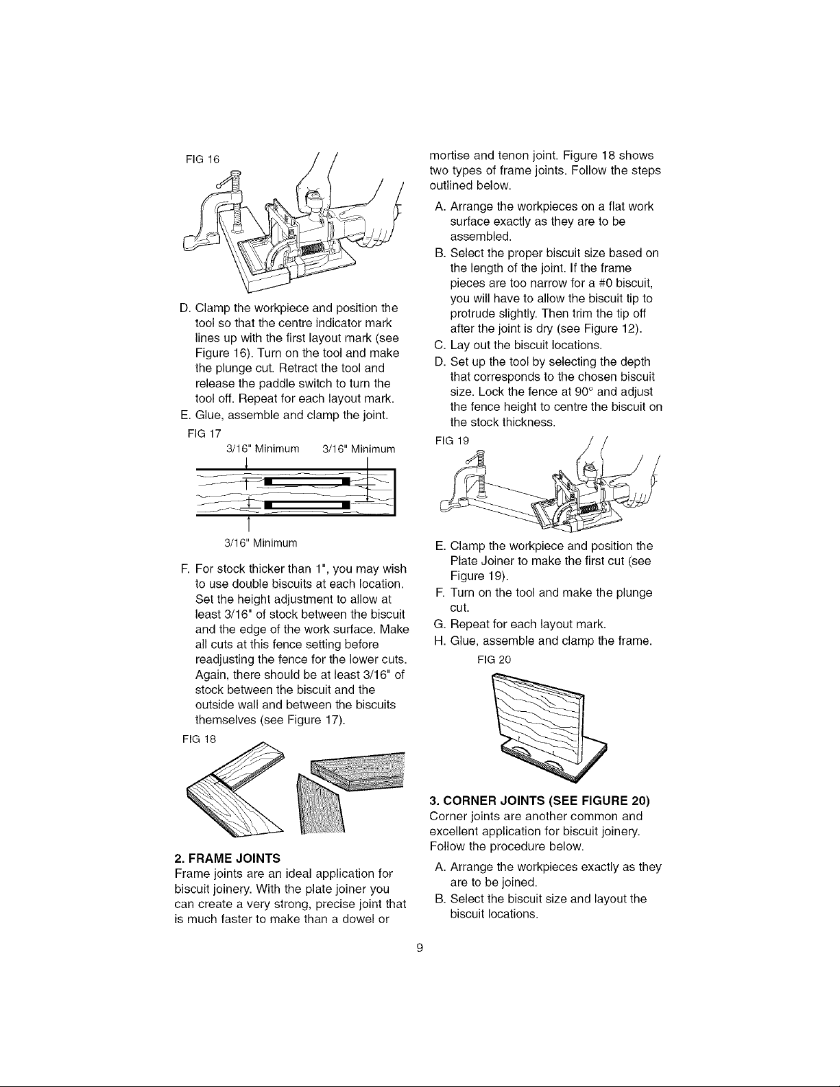
FIG16
D.Clamptheworkpieceandpositionthe
toolsothatthecentreindicatormark
linesupwiththefirstlayoutmark(see
Figure16).Turnonthetoolandmake
theplungecut.Retractthetooland
releasethepaddleswitchtoturnthe
tooloff.Repeatforeachlayoutmark.
E.Glue,assembleandclampthejoint.
FIG17
3/16"Minimum3/16"Minimum
1
3/16" Minimum
F. For stock thicker than 1", you may wish
to use double biscuits at each location.
Set the height adjustment to allow at
least 3/16" of stock between the biscuit
and the edge of the work surface. Make
all cuts at this fence setting before
readjusting the fence for the lower cuts.
Again, there should be at least 3/16" of
stock between the biscuit and the
outside wall and between the biscuits
themselves (see Figure 17).
FIG 18
mortise and tenon joint. Figure 18 shows
two types of frame joints. Follow the steps
outlined below.
A. Arrange the workpieces on a flat work
surface exactly as they are to be
assembled.
B. Select the proper biscuit size based on
the length of the joint. If the frame
pieces are too narrow for a #0 biscuit,
you will have to allow the biscuit tip to
protrude slightly. Then trim the tip off
after the joint is dry (see Figure 12).
C. Lay out the biscuit locations.
D. Set up the tool by selecting the depth
that corresponds to the chosen biscuit
size. Lock the fence at 90° and adjust
the fence height to centre the biscuit on
the stock thickness.
FIG 19
E. Clamp the workpiece and position the
Plate Joiner to make the first cut (see
Figure 19).
F. Turn on the tool and make the plunge
cut.
G. Repeat for each layout mark.
H. Glue, assemble and clamp the frame.
FIG20
2. FRAME JOINTS
Frame joints are an ideal application for
biscuit joinery. With the plate joiner you
can create a very strong, precise joint that
is much faster to make than a dowel or
3. CORNER JOINTS (SEE FIGURE 20)
Corner joints are another common and
excellent application for biscuit joinery.
Follow the procedure below.
A. Arrange the workpieces exactly as they
are to be joined.
B. Select the biscuit size and layout the
biscuit locations.
 Loading...