

Page 1
_ Owner's Manual
Model No. 875.199810
3/8-in. Impact Wrench
Unpacking
When unpacking this product, Carefully
inspect for any damage that may have
occurred during _ransit. Make sure any
ioose _ttings,bolts,etc. are tightened
before pt_ting this product into sewice.
WARNING: Please read and save these safety and ope[aUng instructions. Read carefully
before attempting to assemble, Install, operate or maintain _e ploduct described.
Prefect yourse/f and others by observing all safety information. Failure to comply with
instJructions could result In personal injury arid/or property danlege! Retain Instrucfions
for future reference.
Sears, Roebuck and Co., Hoffman Estates, IL 60179 0807
www.CRAF_SMAN.com
Page 2
Owner's Manual Model No. 875.199810 Owner's Manual Model No. 875.199810
90 PSi M_mum
This tool is designed to operate at an air
• Features & Benefits
SpeCifications
,_ Product W'arranty
Oomp_so{ Requirements
• important Safety Instructions
• Installation and Operation
Maintenance
+ Exploded View Drawing & Parts List
• Troubleshooting
The Craftsman Model 875.199810 3/8"
Square Drive Impact Wrench is ideal for
general assembly, automotive, ag_culfur_d
and lndustda_applications. Features ,_
Built-in regulator for power Q_utput
ad}ustmen_;pJr_type clutc_hfor increased
power output; ring_/pe socket retainer
aflow_ quick socket changes,
Drive s_ze ........................................... 318"
Impacts per minute .................. 1,100 IPM
Free speed (No Load) ........... 9,000 RPM
Ultimate torque ........................ 145 it. Ibs,
Weight ........................................... 2.8 Ibs.
Ovefali' h_ngth.................................... 6.5 _
Average air consumption ........ 3,5 SCFM
Recommended hose size .......... 3/8" f.D.
Air inlet ....................................... I!4" NPT
Maximum Air Pressure .................. fl0 PSI
ONE YEAR FULL WARRANTY ON
CRAFTSMAN TOOL
}f this Cfa_:sman tool fails to give complete
satisfaction _in one year from the dale
of purchase, RETURN IT TO ANY SEARS
STORE OR OTHER cRAFTSMAN
OUTLET IN THE UNITED STATES FOR
FREE REPLACEMEN£
ffthis Craftsman tool is ever used for
commerciaf or renal purples, this
warranty applies for orgy 90 days from the
date of purchase. This warranty does not
include expendable parts, such as lamps,
batteries, _ or blades. This warranty
gives you specific legal _Jhts. and you
may also have other rights which vary
from state to state.
,,_ws, Roebuck and Co.,
Hotfn_n Estates, _. S017e
Light Use- 12 Gatlo_
Typical Use. 17 Ga|lon
Heavy Use - 33 Gallon Profee_|onal
Read Operating In_0'l_ctions
Please becon_ familiar with all the
insP=_Jo,",s a_'_ _,-a_Ings b_fore
operating any pneumatic toot,
AlwaysWearApproved EyeProt_,tion
Impactresistanteyeprotectionshould
meetor exceedthe standarcissetforth in
ANS!ZBT.1,Occupationaland
EducationalEye andFace Protection.
LookformaWjngZ87,1 onyoureye
protectionto ensure_at ft is an approved
style.
Hearieg Protection is Recommended
Heanng protection shouk_ be used when
the noise level exposure equals or
exceeds an 8 hour time-weighted average
sound level of 85dBA. Process noise,
reflective surfaces, other tools being
operated nearby, all add tothe noise [eve|
Jna given wo_ area_ if you a_e unable to
determine your noise _evet exposure, we
recom,-_d the use of hearing pretect'_n.
Avoid Prolonged Exposure to Vibration
Pneum__ticto_s can vibrate dudng _se.
Prolonged e_posure to uCbralionor very
repetitive hand and arm movements can
cause injuq/. Discontinue the use of any
tool if you experience tingling, numbness,
discomfort or pain in your hands or arms,
You should consult your physician before
resuming use of tool.
pressure of 90 pounds per square inch
gauge pressure (90 PSI) maximum, at the
toG. U_e of higher air pre_sure can, and
may cause injuPj. Also, tt_ use _f higher
air pressure places the internal
components under loads and stresses
they were net designed for, causing
premature tool failure.
C,zdifomia Prop 65
Some du_t crea_ed by power sanding,
sawing, grinding, drilling and o_er
construction activities contains
chemicals known to cause cancer, birth
defects or other reproduc_ve harm.
Some examples of these chemicals are:
Lead from lead based paim, crystalline
silica from bricks and cement and other
masonry products, arsenic an_l
ch_mium from chemically-treated
lumber.
Your risk from those exposures varies,
depending on how often you do this
type of worP.. To t_duce your exposure
to these chemicals: work in a welt
veedilated area, at_i work wfth approved
safety equipment, such as dust masks
that are SpeciftcJ41y designed to filter
out microscopic p_rticles.
ENG~2 _NG-3
Page 3
Owner's Manual Model No. 875.199810 Owner's Manual Model No. 875.199810
Discoi_nect the air tool from air supply
before.changir_ tools or atta_menls_ .....
servicing and during non-operation.
DO not wear loose fitting clothing,
scarves, orneck ties in work area. Loose
clothing may become Caught in moving
paris and result in serious personal injury.
Do not wear jewelry when operating
any tool. Jewelry may become caught in
moving partsand result in serious
personal injury
Do not deprasS trigger when connectin9
the air supply hose.
Never trigger the tool when not applied
to a work object.
Attachments must be securely
attached. Loose attachments can cause
sedous injury.
Protect air lines from damage or
pullcture.
Never point an air tool at oneself or any
other parson. Serious injury could occur.
Check air hoses for weak or worn
conditions before each use. Make sum all
connections ate secure.
Release all pressure from the system
before attempting to install, service,
relocate or perform any maintenance.
Keep allnuts, bolts and screws tight
and ensure equipment is in safe working
condition.
ENG-4 ENG-5
air powered tool Always examine
accessories before mounting for chips,
cracks, or signs of damage.
Never use mounted points or other
accessories that have been dropped or
exposed to water, solvent or extreme
temperature changes. It is a good practice
to operate the tool in a protected
enclosure for one minute after mounting
any accessory.
Always use accessories with an RPM
rating that meets or exceeds the tool
RPM taUng.
Never cany a tool by the hose or putl
the hose to move the tool or a
compressor. Keep hoses away from
heat, oil and sharp edges, Replace any
hose that is damaged, weak or worn.
Inhalation hazard: Abrasive tools, sj.__h
as g#nders, sanders and cut-off tools
generate dust end abrasive materials
which can be harmful to human lungs
and respiratory system. Always wear
MSHA/NIOSH approved, properly rdting
face mask or respirator when using
such tools.
SOme materials such as adhesives and
could cause serious injury with
prolonged exposure. Always work in a
clean, day, well ventilated area.
Tools which contain moving elements,
or drive other moving tools, such as
gnnding wheels, sockets, sanc_ng
discs, etc_, can become entangled in
hair, clothing, jewelry and other loose
objects, resulting in severe injury.
Never wear loose t_ffing apparel which
contains loose straps or ties, that could
become tangled m moving parts of the
tool. Remove any Jewelry_ watches, etc.,
which might become caught by the
tool Keep hands away from moving
parts. Tie up or cover long hair.
Improperly maintained tools and
accessories can cause serious injur F
Maintain the tool with care. A properly
ma{ntaiBed tool, with sharp cutting
edges, reduces the risk of binding and
is easier to control.
There is a risk of bursting if the tool is
damaged. Check for misalignment or
binding of moving parts, breakage of
parts and any other condition that
affects the fool's operation, ff damaged,
have the tool serviced before using.
Too_ whP..h cut, sheer, ddll, staple,
punch, r__hiseJ,etc. =re capable of
causing serious injury. Keep the
working part of the tool away from
hands and body,
After an air tool has been lubricated, oil
will discharge through the exhaust port
during the first few seconds of
operation. Thus, the exhaust port must
be covered with a towel before applying
air pressure.
Only use sockets designated "FOR USE
WITH IMPA C T WRENCHES. "Hand tool
sockets can break, creating a hazard
from flying pieces. Always check
sockef_ retainers and drives regularly
for wear or damage and replace when
necessary.
Page 4
Owner's Manual Model No. 875.199810 Owner's Manual Model No. 875.199810
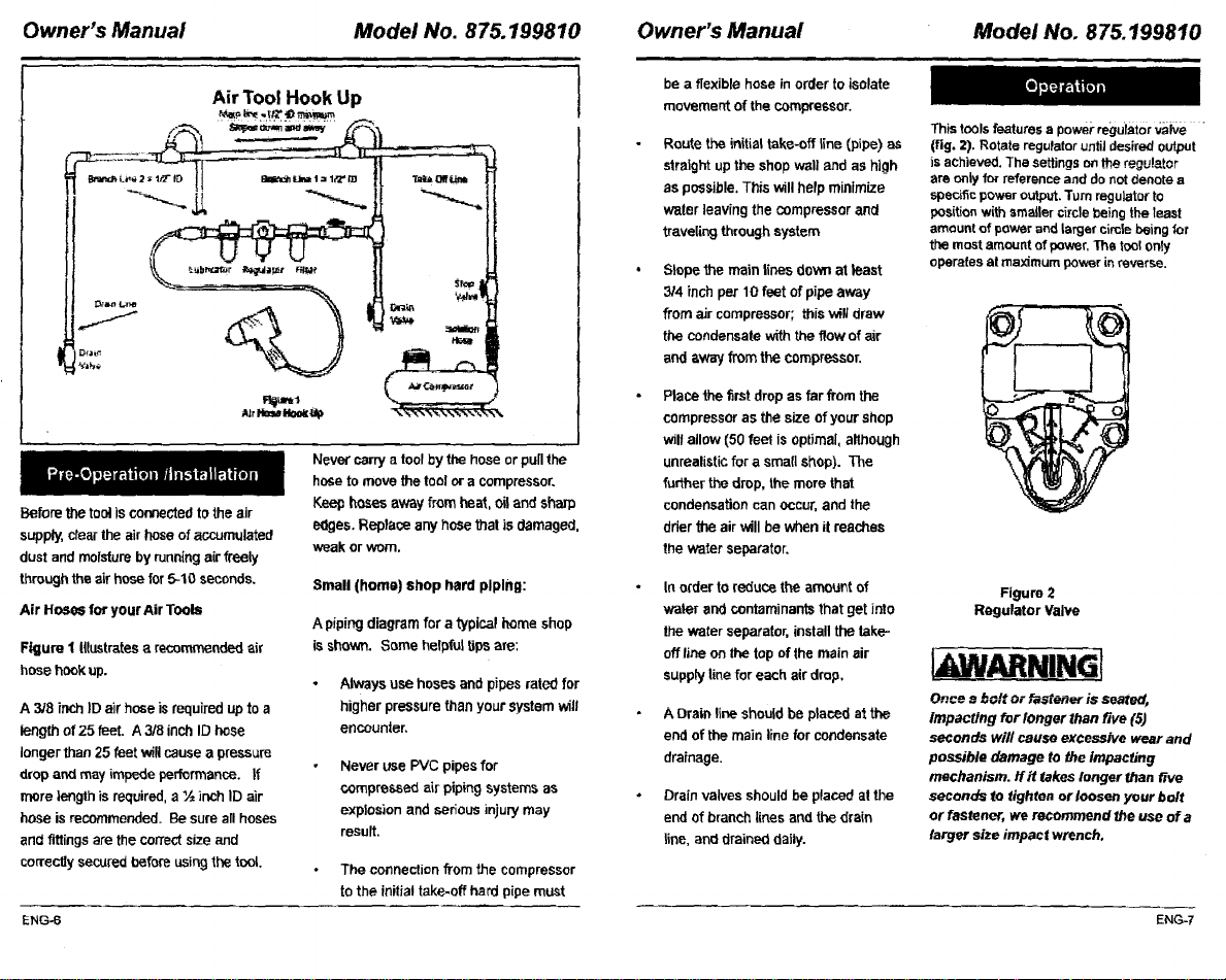
Air Tool Hook Up
Never carry a tool by the hose or pu[Ithe
hose to move the tool or a compressor.
Before the tool is connected to the air
supply, dear the air hose of accumulated
dust and moisture by runn{ng air freely
through the air hose for 5-10 seconds.
Air HoseS for yourAir Tools
Figure 1 Illustrates a recommended air
hose hook up.
A 3/8 inch ID air hose is required up to a
length of 25 feet. A 3/8 inch ID hose
longer than 25 feet will cause a pressure
drop and may impede performance. If
more length is required, a ½ inch ID air
hose is recommended. Be sure all hoses
and fittings are the correct size and
correctly secured before using the tool.
ENG-6 ENG-7
Keep hoses away from hea_, oil and sharp
edges. Replace any hose thai is damaged,
weak or worn.
Small (home) shop hard piping:
A piping diagram for a typical home shop
is shown. Some helpful tips are:
• Always use hosesandpipesratedfor
higherpressurethanyourSystemwill
encounter,
Never use PVC pipes for
compressed air piping systems as
explosion and serious injury may
result.
The connection from the compressor
to the initial take-off herd pipe must
be a flexible hose in order to isolate
movement of the compressor.
Route the initial take-off line (pipe) as
straight up the shop wall and as high
as possible, This will help minimize
water leaving the compressor and
traveling through system
Slope the main lines down at least
3/4 inch per 10 feet of pipe away
from air compressor; this will draw
the condensate with the flow of air
and away from the compressor.
Place the first drop as far from the
compressor as the size of your shop
wiltallow (50 feet is optimal, although
unrealistic for a small shop). The
further the drop, the more that
condensation can occur, and the
dher the air will be when it reaches
the water separator.
In older to reduce the amount of
water and contaminants that get into
the water separator, install the take-
offline on the top of the main air
supply line for each air drop,
A Drain line should be placed at the
end of the main line for condensate
drainage.
Drain valves should be placed at the
end of branch lines and the drain
line, and drained daily.
This toolsfeatures a power regulator ,a_zlve
(fig. 2). Rotate regulatoruntiJ desired output
is achieved. The settings on the regu!etor
are only for reference and do not denote a
specific power output.Turn regulator to
position with smaller circle being the least
amount of power end largef circle being/or
the most amount of power, The tool only
operates at maximum power in reverse.
Figure 2
Regulator Valve
•ARNINGI
Once ,_bolt Or Pastener is seated,
Impacting for longer than five (5)
seconds will cause excessive wear and
possible damage to the Impacfing
mechanism, flit takes longer than five
seconds to tighten or loosen your bolt
or fastener, we recommend the use of a
larger size impact wrench.
Page 5
Owner's Manual Model No. 875.199810 Owner's Manual Model No. 875.199810
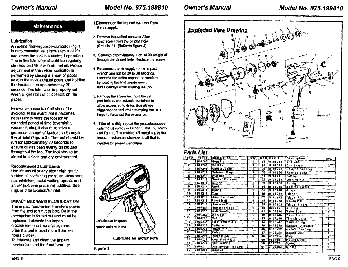
1.Disconnect the impact wrench from
theairsupply.
Lubdcatien
An in-line filter-regulator-lubricator (fig 1)
isrecommended as it increases tool life
ar_l keeps the tool insustained operation.
The in-line lubdcalor should be mgulady
checked and tiffedwith air loot oar.Proper
adjustment of the ir_line lubltcator is
performed by placing a sheet of paper
next to the tools exhaust ports and holding
the throttle open approxfmateiy 30
seconds. The lubricator is properly set
when a light stain of oil COfleCISon Ihe
paper.
Excessive amounts ofoil should be
avoided, fn the event that it becomes
necessary to store the tool for an
extended period of time (overnight,
weekend, etc.), it should receive a
generous amount of lubrication through
the air inlet (Figure 3). The tool should be
run for aptxoximatoly 30 seconds to
ensure oil has been everdy distributed
throughout thetool The tool should be
stored in a clean and dry environment.
Recommended Lubricants
Use air leo; oi!or any other high grade
turbine ogco_ltaining moisture absorbent,
rust inh_itors, metal _et_ng agents and
an EP (extreme pressure) addllive. See
Figure 3 for lecalion/air inleL
IMPACT MECHANISM LUBRICATION
The impact mechanism transfers power
from the toot to a nut or bolt. Oil in the
mechanism isforced out and must be
replaced. Lubricate the impact
mechanism one time a year, more
often If a tool is used more than ten
hours a week.
To lub_qcateand clean the impact
mechanism and the front bearing:
ENG-8 ENG-g
2. RRnlOvo the siol;ted screw or Allen
head screw from the oil port hole
(Ref, No. 51) (Refer to figure 3}.
3, Squeeze app_oxirrm.tely 1 oz. of 30 weight oil
through the oil port hole. Replace the screw.
4. Reconnectthe air supplyto theimpact
wrenchand runfor 201o 30 seconds.
Luixicate the entire impact mechanism
byrotatingthetool upsidedovm
endsidewayswh_ runningthetool
5. Remove the screw and held the oil
port hole over a suitable container to
allow excess oil to drain. S_n",etim'a,s
_ggefin9 the toof when dur_pang _e oils
helps to lone out the excess oil
6. If the oil is di_3', repeat the procedureabove
until the oil comes out de_'. Install the screw
and tighten. The residual oil remaining _ the
impact mechanism chamber is aftthat is
needed for proper lubrication.
Lubricate impact
mechanism here
Lubricate air motor here
Figure 3
Parts List
Sef# Plrt#
3
4
B.
7
S
_2
_4
15"
t6
t_
18
20 :8i0S2ZS 3e,el Pin
21 tt1062_7 _otor
22 9105229 _oiOr Blade
23 910d22g _ear E_d Plate
24 910B230 gall B ea.-ing
2'_; 9106231 !(_rn_me_t nl Gasket
26 9106232 Gasket
IDBscrIptlo;') I;tty Ref# Part #_
9108207
IH O'Je;in_l -- 1 27 g10S2_$
91052_9
(311 Seal 1 26 gI _162 "_.4
9!0620_
[A nv]l' _ us hins | 2T 910g2_
91D6210
_etainer RIng 1 30 ].106236
_1062tl
A/asher 1 31 976024
9t06212
G¢c_et Retainer 1 32 9?06237
91_0070
_-Ring 1 33 9106236
_106214
_t_J 1 34 9108239
91082i_
5 pFltl9 1 35 9106240
SIO_21S
3am 1 38 9106241
910S217
IDd_ e =tll-_@a! I 37 -_1Q_Z42'
_.teel B;all ? 38 91-08243
916S21_
4immer Pin -- _' 3_ 9106'255
91_$22_
H_mmer_a_. 1 40 gBgG'0g
9105221
Bill Bearing .. t 41 9106244
gt06_22
311 Sea| _ 42 9106245
9106223
_O.-R t0 g i 43 9_ 0S248
Fr_,_t Fnd Piat_ I 44 9106247'
9106,2Z4
9108226
._y|i_d s _" '1 45 gf0s241
I_ sc ription Qty.
End Cap i
_ap ectew 4
P.e_e_s _ VaF/e 1
3-Rin 9 ]
iLo_kln_ F'in I -
_¢rew
ri_oer
'Trigger,P n "_
_prl_g Pin _--
Trig ge t _ le eve f --
Oil P Jug 1
Val_ Seat -- 1
Val'_ Stem
Ti_rot tie Ve.lve
Valve Spring
46 9106262 Air Inlet Bushing - 1
1 _'7 9106253 H==ndle Grip
1 4_1 _6.6._149 M uft}er COV_'_ 1
t 50 S21_7 Sprtn 9 1
Exhaust DeRector 1
Page 6
Owner's Manual Model No. 875.199810 Owner's Manual
,=, ..m , ,
Model No. 875.199810
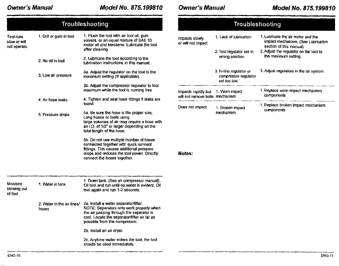
Toolruns
sloworv_ll
notoperate.
Mois_re
browing out
of toot
!. Grit or gum in tool
2. No oil in tool
3, Low air pressure
4. Air hose leaks
5. Pressure drops
1. V_ter in tank
1. Flush the tool with air tool oil, gum
solvent, or an equal mixture of SAE 10
motor oil and kerosene. Lubricate the tool
after cleaning.
2, Lubricate the tool according tO the
lubrication inslruclions in this manual.
3a. Adjust the regulator on the lool to the
maximum setting (If applicable).
3b. Adjust the compressor regulator to tool
maximum while the tool is running free
4. Tighten and seal hose fittings if leaks m'e
found.
5a. Be sure the hose is the proper size.
Long hoses or tools using
large volumes of air may require a hose with
an I.D. of 1/2" or larger depending on the
total lenglh of the hose.
5b. Do not use multiple number of hoses
connected together with quick connect
fittings. This causes additional pressure
drops and reduces the tool power. Directly
connect the hoses together.
1. Drain tank. (See air compressor manual).
Oil tool and run until no water Is evident. Oil
too} again and run 1-2 seconds.
Impactssrowiy
1. Lack of lubrication
orwiltnotimpact
2,Tool regulator set in
wrong position
3. In-line regulator or 3. Adjust regulators in the air system
compressor regulalor
set too low
lmpacls rapidly but 1. Worn impact
will not remove bolts mechanism
Does not impact 1. Broken impact
mechanism
Notes:
I. Lubricate the air motor and the
impact mechanism. (See Lubrication
sectionof this n-_uaT_
2.Adjust the regulator on the tool to
the maximum setting
1.Replace worn impact mechanism
components
1, Replace broken impact mechanism
components
2. Water in the air lines/
hoses
ENG-10 ENG-_I
2a. Install a water separator/fitter.
NOTE: Separators only work properly when
the air passing through the separator is
cool. Locate the separator/filter as far as
possible from the compressor.
2b. Install an air dryer,
2c, Anytime water enters the tool, the tool
should be oiled immediately.
Page 7
I_€ t_tmq _H_de ==_=orm_ / _ Iv_arqu_,nI_le)4 _e Beat_ _randJ, LUG
-==r _ isillli_,a
_P_ IBt=nvJ#, LLC
 Loading...