

Craftsman 842.242560 Owner's Manual
SEARS
.
OWNER'S
MANUAL
MODEL
NO.
842.242560
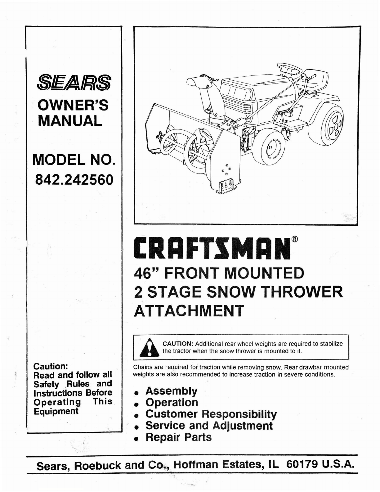
ERAFTSMAN®
46" FRO·NT
MOUNTED
2
STAGE
SNOW
THROWER
ATTACHMENT
h CAUTION: Additional rear wheel weights
are
required to stabilize
ft
the tractorwhen the snow thrower is mounted to
it.
Caution:
Read and follow all
Safety
.,Rules
and
Instructions Before
Operating
This
Equipment
Chains are required for traction while removing snow. Rear drawbar mounted
weights are also recommended to increase traction
in
severe conditions.
•
Assembly'
• Operation
• Customer Responsibility
• Service and Adjustment
• Repair Parts
Sears, Roebuck and
C~'"
Hoffman Estates, IL 60179 U.S.A.
SAFETY RULES
Safe
Operation
Practices
for
the Snow Thrower Attachment
•
Do
not
stoporstart suddenly when
going
uphill or downhill.
• When using
the
vehicle with a snow thrower,
proceed
as
follows:
• Remove snow only in daylight
or
in
good
artificiaJ
light
• Nevermake any adjustments while the engine is
running
if
the
operator
must
dismounttodo
so.
• Shutthe
engine
off when unclogging
chute.
I.
(
(
A
Use
only
approved drawbar hitch points.
Umit
loads to those you can safely control.
Use care when pulling loads
or
using heavy
equipment.
Keep the vehicle and attachments in good operating
condition,
and keep
safety
devices
in
place. When
using
Three
Point
Hitch
remove attachments from hitch before
making
any
repairs on
attachment
or
hitch.
Keep all nuts, bolts,
and
screws tight,
all
cotter pins
and
retainer
springs in place 10be'sure
the
equipmentisin
safe
working
condition. .
Never run snow thrower into
heavy
material
at
high
speeds.
Watch
out
for traffic when crossing
or
near
roadways.
When using
any
attachments, never direct discharge
of
materiaJ
toward bystanders
nor
allow anyone near
the
vehicle while in
operation.
Open doors
if
the
engineisrun in
the
garage; exhaust
fumes
are
dangerous.
Do
not run the engine indoors.
Handle fuel
with care -
it
is
highly flammable.
Use approved fuel containers.
Never remove
the
cap
of
thefuel tank
or
add
fuel10a
running
or
hot engine,orfill the tank indoors. Wipeupspilled fuel.
Do not tum sharply. Use care when backing.
Use counterweights or wheel weights and tire chains when
suggested in this owner's manual.
Never store
equipment'with
fuel in the
tank
inside a
building
where fumes
may
reach an open flame
or
spark.
Allow
the
engines10cool
before storing in any enclosure.
To
reduce fire hazard, keep
the
engine freeofgrass, leaves
or
excessive grease.
•
•
•
•
•
•
•
•
•
•
•
•
•
• The vehicles
and
attachments shouldbestopped
and
inspected
fordamageafterstrikinga foreign object,
and
the
damage
should
be
repaired before restarting
and
operating
the
equipment.
• Do not change the engine governor settings
or
overspeed
the
engine.
•
•
•
A
Reduce speed on slopes and make turns gradually to prevent
tippingorlossofcontrol. Exercise
extreme
caution when
changing
direction on slopes,
Do
not
shift gears while going upordown
slopes. Choose a
gear
low
enoughtonegotiate the slope
without
stopping
and
shifting gears.
Stay alert for
holes
in the terrain and other hidden hazards.
Do
not
drive
too
closetocreeks, ditches
and
public highways.
Disengage power
to
attachments and
stop
the engine before
leaving the operator's position.
Take all possible precautions when leaving the vehicle
unattended, such
as
disengaging the
attachment
clutch lever
or
switch, lowering
the
attachments,shift
tractor
into
neutr~,
setting
the
parking brake,
stopping
the engine,
and
removing
the
key.
Disengage all
power
to snow thrower,
stop
the engine, remove
key
from
ignition switch before cleaning,
makinganadjustment
or
repairs.
Disengage all
attachment
clutches and
shift
into neutral before
attemptingtostart the engine.
Drive slowly when front
or
rear
mounted
attachment is in
transport position.
Disengage
powertoattachments when transporting or not
in
use.
Always
getonor
off
your
tractor from the operators left side.
Clear the work area of objects which
mightbepicked up
and
thrown.
Always wear substantial footwear.
Do
not
wear loose fitting
clothes
that
could
get
caught
in moving parts.
Keep
your
eyes and
mind
on your tractor, snow thrower and
the
area
being
cleaned.
Don't
let other interests distract you.
Do
not
attempttooperate
your
tractor or
snow
thrower when
not
in the drivers seat.
Do not carry passengers. Keep children and pets a safe
distance away.
Know the controls
and
how
to stop quickly.
READ
THE
OWNER'S MANUAL .
Do
not
allow children to operate vehicle.Donot allow adults
to
operate it without
proper
instruction.
•
•
•
•
•
•
•
•
•
•
•
•
•
•
•
•
•
•
•
Exercise special car6 when removing snow around fixed objects
in order to
prevent
the blades from
striking
them: Neller
deliberately run tractor
or
snow thrower
intoorover any foreign
objects.
• Additional rear wheel weights are required to stabilize the
tractor when the snow throwerismounted to it.
• Never shift gears until tractor comes to a stop.
•
Never place
hands
or
feet
near the snow
auger,inthe
deflector
(discharge
chute)
or
near any moving
parts
while tractor
or
snow
thrower
is running.
/JJways
keep clearofdischarge
chute.
LOOK
FOR
THIS
SYMBOLTOPOINT
alIT
IMPORTANT
SAFETY
PRECAUTIONS.ITMEANS-ATTENTION!
BECOME
ALERT!
YOUR
SAFETYlSIt-.'VOLVED.
2
CONGRATULATIONS on your purchase of a Sears Craftsman
Snow
Thrower. It has been designed, engineered and
manufactured
to
give you the best possible dependability
and performance.
Should
you
experience any problem you cannot easily
remedy, please contact your nearest Sears Service
Center
/Department. We have competent, well-trained
te~hnicians
and the proper toolstoservice or repair this
Unit.
Please read and retain this manual. The instructionswill
enable
youtoassembleand maintain yourSnowThrower
properly. Always observethe "Safety Rules."
MODEL
NUMBER: 842.242560
SERIAL
NUMBER, _
DATE OF
PURCHASE _
THE MODEL AND SERIAL NUMBERS WILL
BE FOUND ON A PLATE ATTACHED TO THE
LEFT SIDE OF THE AUGER HOUSING.
YOU SHOULD RECORD BOTH SERIAL
NUMBER AND DATE OF PURCHASE AND
KEEP IN A SAFE PLACE
FOR
FUTURE
REFERENCE.
CUSTOMER RESPONSIBILITIES
• Read and observe the safety rules.
• Follow a regular schedule in maintaining, caring
for
and using your Snow Thrower.
• Follow the instructions under "Customer Responsibilities" and "Storage" sections of this Owner's
Manual.
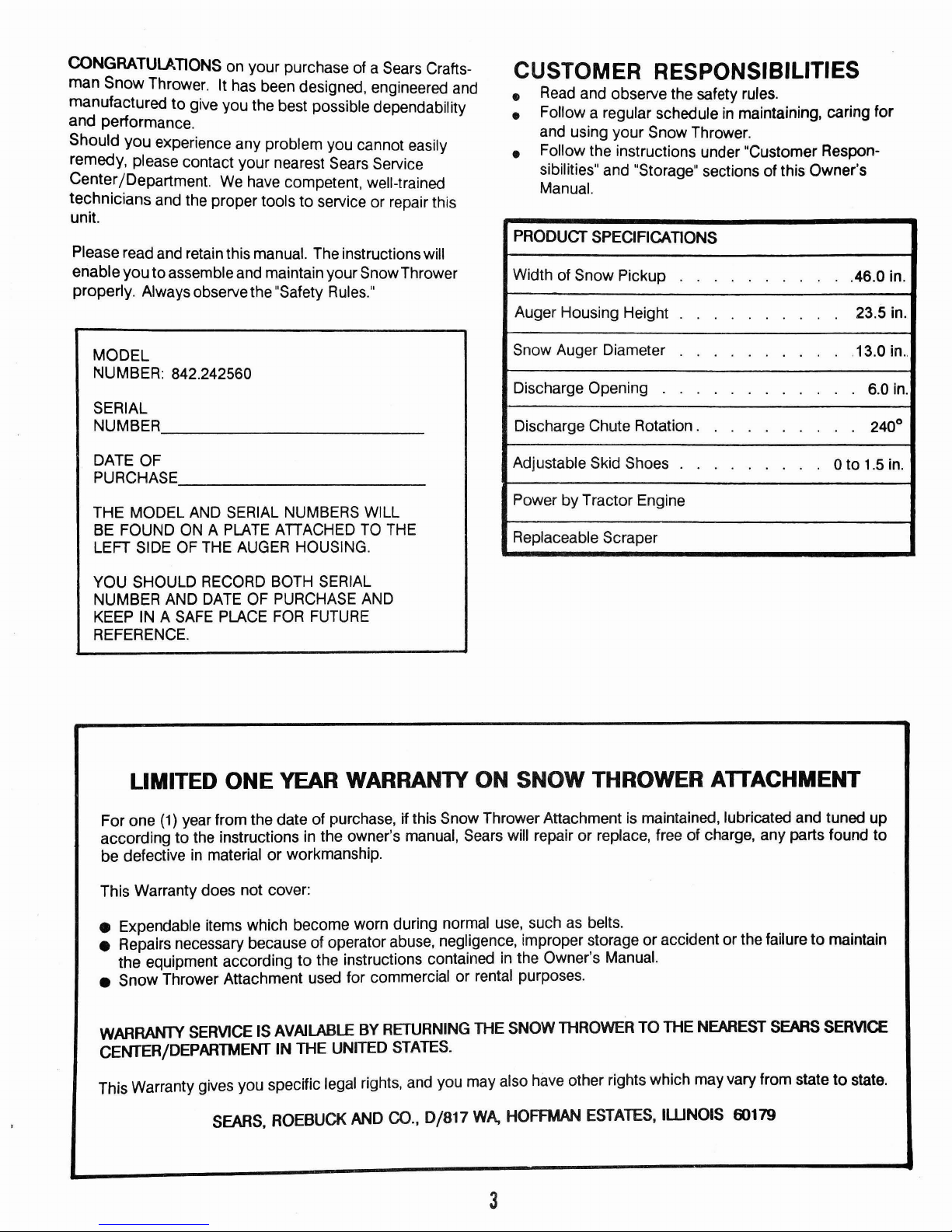
PRODUCT SPECIFICATIONS
Width of Snow Pickup
.46.0 in.
Auger Housing Height 23.5 in.
Snow Auger Diameter
,13.0
in.,
Discharge Opening
6.0
in.
Discharge Chute Rotation.
240
0
Adjustable Skid Shoes
o
to
1.5
in.
Power by Tractor Engine
Replaceable Scraper
LIMITED ONE YEAR WARRANTY ON SNOW THROWER AlTACHMENT
For one
(1)
year from the date of purchase, if this Snow Thrower Attachment is maintained, lubricated and tuned
up
accordingtothe instructions in the owner's manual, Sears will repairorreplace, free of charge, any parts found
to
be
defectiveinmaterialorworkmanship.
This Warranty does not cover:
• Expendable items which become worn during normal use, such as belts.
• Repairs necessary because of operator abuse, negligence, improper storage or accident or the failure
to
maintain
the equipment according
to
the instructions contained in the Owner's Manual.
• Snow Thrower Attachment used for commercial or rental purposes.
WARRANTY SERVICE IS AVAILABLE BY RETURNING THE SNOW THROWER TO THE NEAREST SEARS SERVICE
CENTER/DEPARTMENT IN THE UNITED STATES.
This Warranty gives you specific legal rights, and you may also have other rights which may vary from state
to
state.
SEARS. ROEBUCK AND
CO.,
0/817
WA. HOFFMAN ESTATES,
IWNOIS
60179
3
TABLE OF CONTENTS
(
Safety Rules................. 2
Customer Responsibilities..................................... 3
Warranty...............................................................
3
Product Specifications........................................... 3
Accessories........................................................... 5
ContentsofHardware Bag..................................... 6-7
Contents
of
Carton................................................ 8
INDEX
A
Accessories...........................................................
5
Adjustments:
Skid Shoes......................................................... 23
Lift Assist Springs............................................... 24
Discharge Chute........ 24
Discharge Chute Drive Tube.......... 24
Lift Height.. 23
Side To Side Leveling 23
B
Belt:
Installation 14-16
C
Controls:
Attachment Clutch Switch..................................
18
Snow Thrower Lift Handle..................................
18
Chute Control Rod.........................
18
Snow Deflector Control Handle.......................... 18
Customer Responsibilities:
Maintenance Schedule
21
Lubrication Chart................................................
21
D
Drive Chain:
Installation And Adjustment................................
14
F
Finish:
Maintenance...................................................... 25
(See Storage)
L
Lubrication:
Lubrication Chart................................................ 22
4
Assembly..............................................................
17
Operation 18-20
Customer Responsibilities 21-22
Service
&Adjustments 23-24
Storage................................................................. 25
Troubleshooting.........
26
Repair Parts 27-33
Service Notes 34-35
o
Operation:
Know your Snow Thrower
18
Controls.............................................................
18
Stopping..........................................
19
Transport
19
To Remove Snow...........
19
Operating Suggestions 20
R
Repair Parts 27-33
Rules For Safe Operation
2 '
S
Service And Adustments:
Drive Chain....... 24
Lift Assist Springs............. 24
Lift Height......... 23
Side to Side Leveling........................................ 23
Skid Shoes....................................................... 23
Service:
Maintenance Schedule
21
Storage................................................................ 25
Snow Removal:
To Remove Snow.............................................
19
Operating Suggestions 20
Specifications...................................................... 3
T
Troubleshooting Chart
..
26
W
Warranty.............................................................. 3
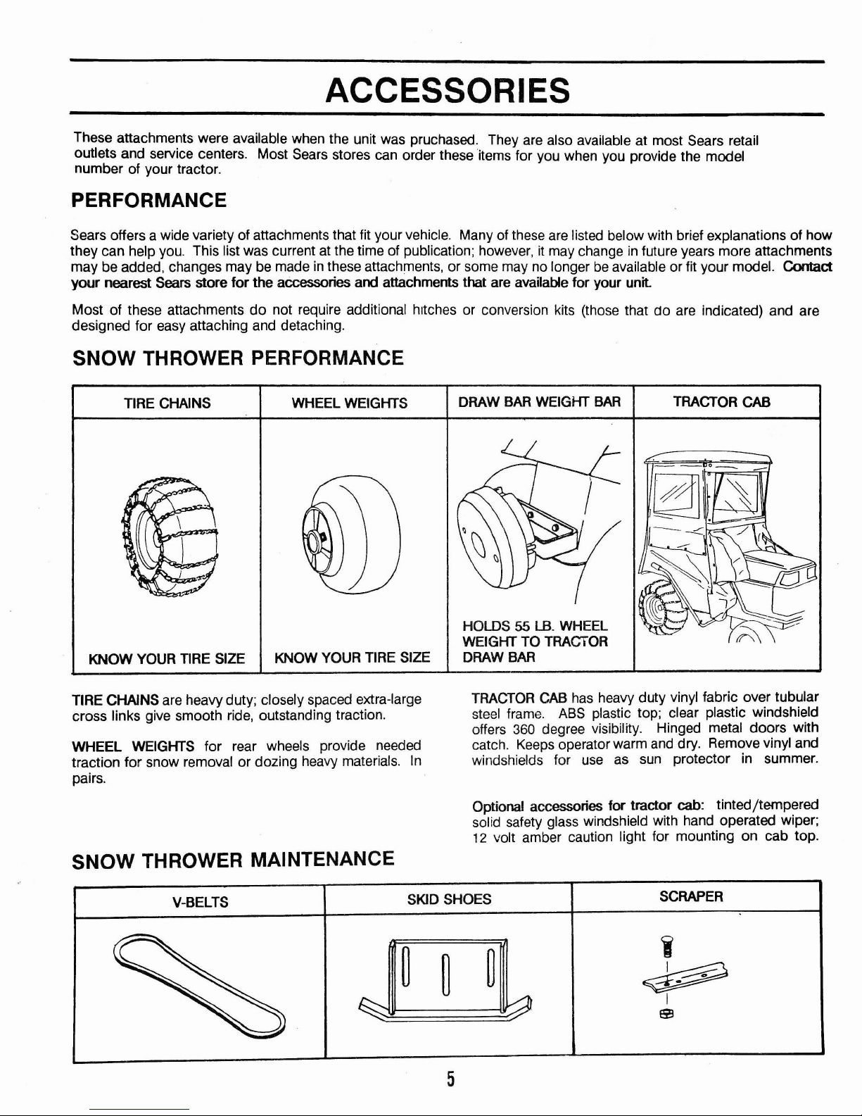
ACCESSORIES
These attachments were available when the unit was pruchased. They are also available at most Sears retail
outlets and service centers. Most Sears stores can order these items for you when you provide the model
number of your tractor.
PERFORMANCE
Sears offers a wide variety of attachments that fit your vehicle. Many of these are listed below with brief explanations of how
they can help you. This list was current at the time of publication; however,
it
may changeinfuture years more attachments
may be added, changes may be made
in
these attachments, or some may no longerbeavailable or fit your model. Contact
your nearest Sears store for the accessories and attachments that are available for your unit.
Most of these attachments
do
not require additional hItches or conversion kits (those that do are indicated) and are
designed for easy attaching and detaching.
SNOW THROWER PERFORMANCE
TIRE CHAINS
WHEEL WEIGHTS
DRAW
BAR
WEIGHT
BAR
TRACTOR
CAB
HOLDS 55
LB.
WHEEL
WEIGHT TO TRAGrOR
DRAW
BAR
KNOW YOUR
TIRE
SIZE
KNOW YOUR
TIRE
SIZE
TIRE CHAINS are heavy duty; closely spaced extra-large
cross links give smooth ride, outstanding traction.
WHEEL WEIGHTS for rear wheels provide needed
traction for snow removal or dozing heavy materials.
In
pairs.
SNOW THROWER MAINTENANCE
TRACTOR
CAB
has
heavy duty vinyl fabric over tubular
steel frame.
ASS
plastic top; clear plastic windshield
offers
360
degree visibility. Hinged metal doors with
catch.
Keeps
operator warm
and
dry. Remove vinyl and
windshields for
use
as
sun
protector in summer.
Optional accessories for tractor
cab: tinted/tempered
solid safety glass windshield with hand operated wiper;
12
volt amber caution light for mounting on cab top.
V-BELTS
SKID SHOES
SCRAPER
5
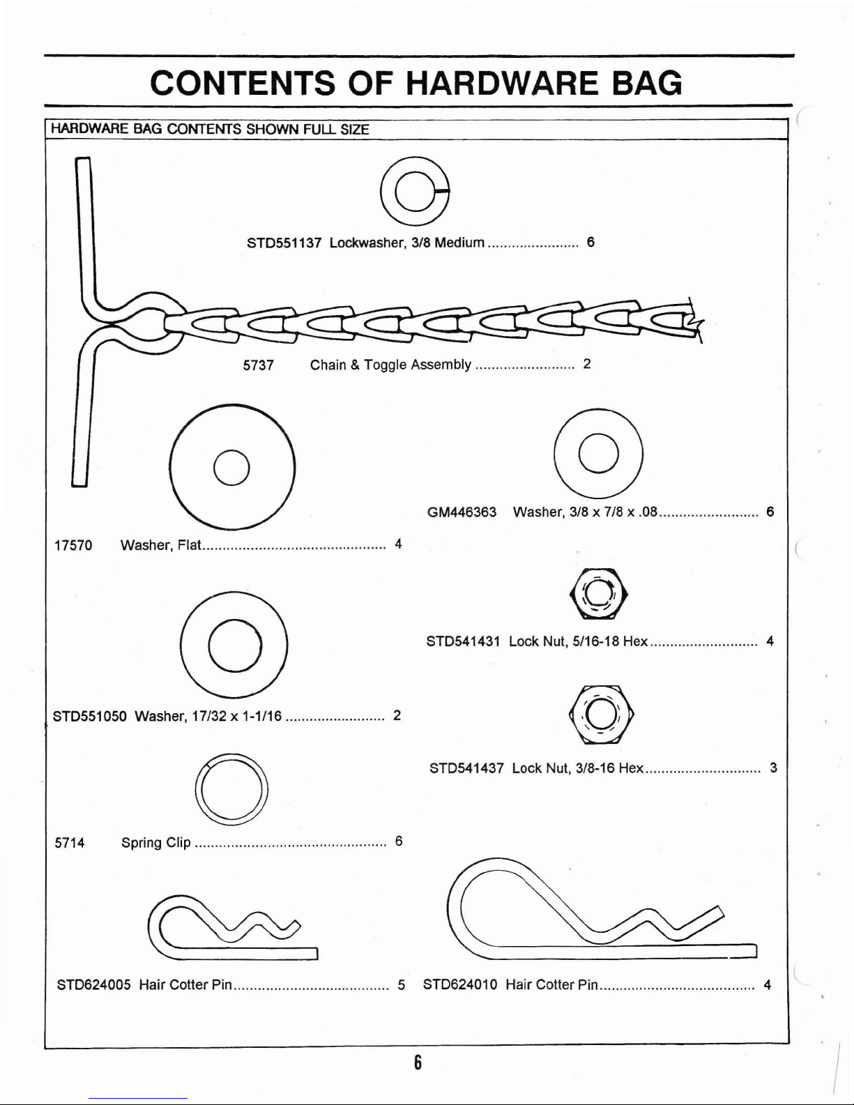
CONTENTS OF HARDWARE
BAG
HARDWARE BAG CONTENTS SHOWN FULL SIZE
©
STD551137 Lockwasher, 3/8 Medium 6
5737 Chain &Toggle Assembly......................... 2
GM446363 Washer, 3/8 x 7/8 x
.08
6
17570 Washer, Flat............ 4
STD551050 Washer, 17/32 x 1-1/16 2
o
5714 Spring Clip 6
~I
@
STD541431 Lock Nut, 5/16-18 Hex 4
@
STD541437 Lock Nut, 3/8-16 Hex 3
STD624005 Hair CoUer Pin............. 5 STD624010 Hair Cotter Pin 4
6
/
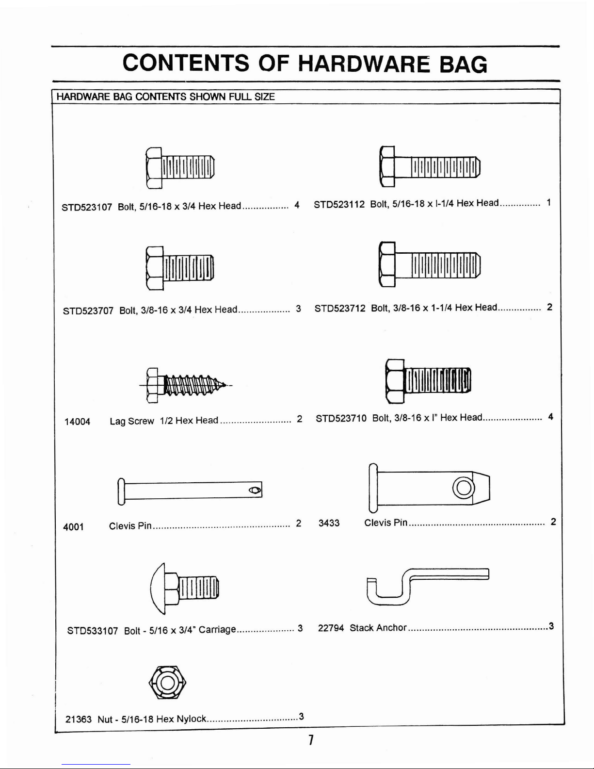
CONTENTS OF HARDWARE
BAG
HARDWARE BAG CONTENTS SHOWN FULL SIZE
STD523107 Bolt, 5/16-18 x 3/4 Hex Head 4 STD523112 Bolt, 5/16-18 x
1-1/4
Hex Head 1
STD523707 Bolt, 3/8-16 x 3/4 Hex Head 3 STD523712 Bolt, 3/8-16 x 1-1/4 Hex Head 2
14004
Lag
Screw 1/2 Hex Head 2 STD523710 Bolt,
3/8-16xl"
Hex Head 4
4001
0_--
01
Clevis Pin
··..···..· 2 3433
Clevis Pin.................................................. 2
STD533107 Bolt - 5/16 x
3/4'
Carriage 3 22794 Stack Anchor
3
21363 Nut - 5/16-18 Hex Nylock
3
7
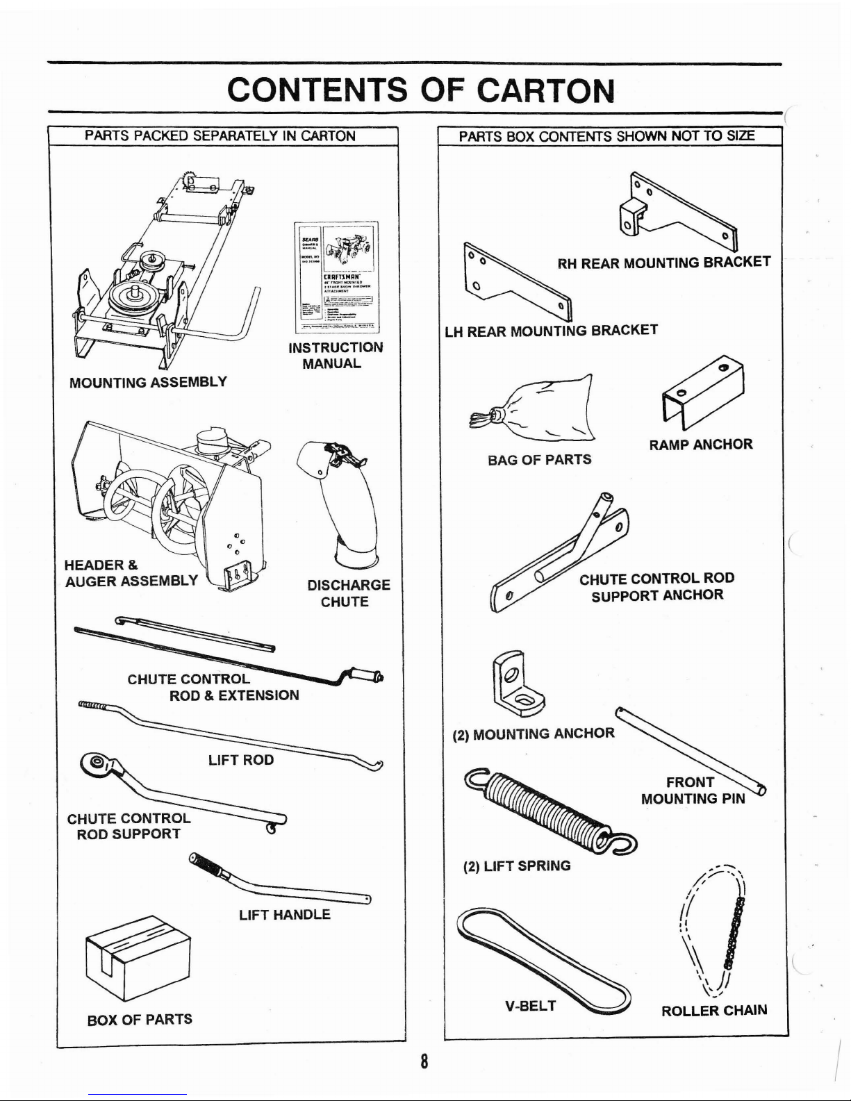
CONTENTS OF CARTON
------------------------------(
PARTS PACKED SEPARATELY IN
CARTON
PARTS
BOX
CONTENTS SHOWN NOT TO
SIZE
(
RAMP ANCHOR
CHUTE CONTROL ROD
SUPPORT ANCHOR
RH
REAR MOUNTING BRACKET
BAG OF PARTS
LH REAR MOUNTING BRACKET
DISCHARGE
CHUTE
INSTRUCTION
MANUAL
<J
"
<J
"
MOUNTING ASSEMBLY
HEADER
&
AUGER
ASSEMBLY
I
~;:--:-:\
I'
/ l
'I
(,
.,
~
\'Ji
\"-"
ROLLER
CHAIN
(2)
LIFT
SPRING
(2) MOUNTING ANCHOR
8
LIFT HANDLE
LIFT
ROD
CHUTE CONTROL
ROD & EXTENSION
BOX
OF PARTS
...,
ASSEMBLY
TOOLS REQUIRED FOR ASSEMBLY
A socket wrench set will make assembly easier.
Standard wrench sizes are listed.
(1) Knife
(1) 3/8" Open
End
or Socket Wrench
(1) 7/16" Open
End
or Socket Wrench
(2) 1/2" Open
End
or Socket Wrench
(2) 9/16" Open
End
or Socket Wrench
(2) 3/4" Open
End
Wrench
TO REMOVE UNIT FROM CARTON
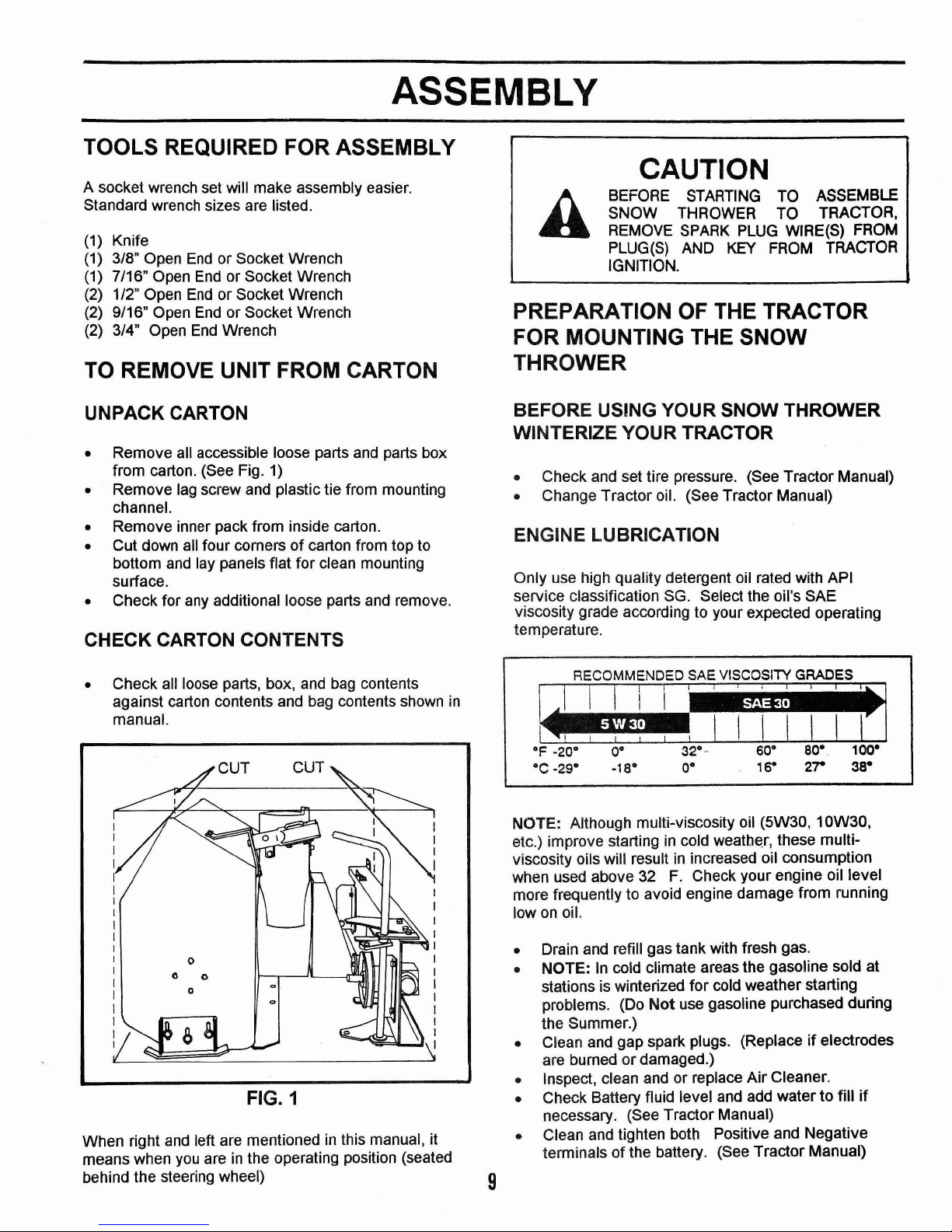
UNPACK CARTON
• Remove all accessible loose parts
and
parts box
from carton. (See Fig.
1)
• Remove lag screw and plastic tie from mounting
channel.
• Remove inner pack from inside carton.
• Cut down
all
four cornersofcarton from top to
bottom
and
lay panels flat for clean mounting
surface.
• Check for
any
additional loose parts and remove.
CHECK CARTON CONTENTS
• Check all loose parts, box,
and
bag
contents
against carton contents and bag contents shown
in
manual.
FIG. 1
When right
and
left are mentionedinthis manual, it
means when
you
areinthe operating position (seated
behind the steering wheel)
9
CAUTION
BEFORE
STARTING
TO ASSEMBLE
SNOW THROWER TO TRACTOR,
REMOVE
SPARK
PLUG
WIRE(S) FROM
PLUG(S) AND
KEY
FROM
TRACTOR
IGNITION.
PREPARATION
OF
THE TRACTOR
FOR MOUNTING THE SNOW
THROWER
BEFORE USING YOUR SNOW THROWER
WINTERIZE YOUR TRACTOR
• Check and set tire pressure. (See Tractor Manual)
• Change Tractor oil. (See Tractor Manual)
ENGINE LUBRICATION
Only use high quality detergent oil rated with API
service classification SG. Select the oil's SAE
viscosity grade according to your expected operating
temperature.
~
OF
-20° 0° 32°··
60·
80·
100·
°e
.29·
·18°
O·
16·
2r 38°
NOTE: Although multi-viscosity oil (5W30, 10W30.
etc.) improve startingincold
weath~r,
these multi-
viscosity oils will result
in
increased oil consumption
when used above
32
F.
Check your engine oil level
more frequently to avoid engine damage from running
low
on
oil.
• Drain and refill gas tank with fresh gas.
• NOTE:Incold climate areas the gasoline sold at
stations is winterized for cold weather starting
problems. (Do
Not
use gasoline purchased during
the Summer.)
• Clean and gap spark plugs. (Replace
if
electrodes
are burned or damaged.)
• Inspect, clean and or replace
Air
Cleaner.
• Check Battery fluid level
and
add watertofill
if
necessary. (See Tractor Manual)
• Clean and tighten both Positive and Negative
terminals of the battery. (See Tractor Manual)
ASSEMBLY
-----------------------(
REMOVE THE MOWER
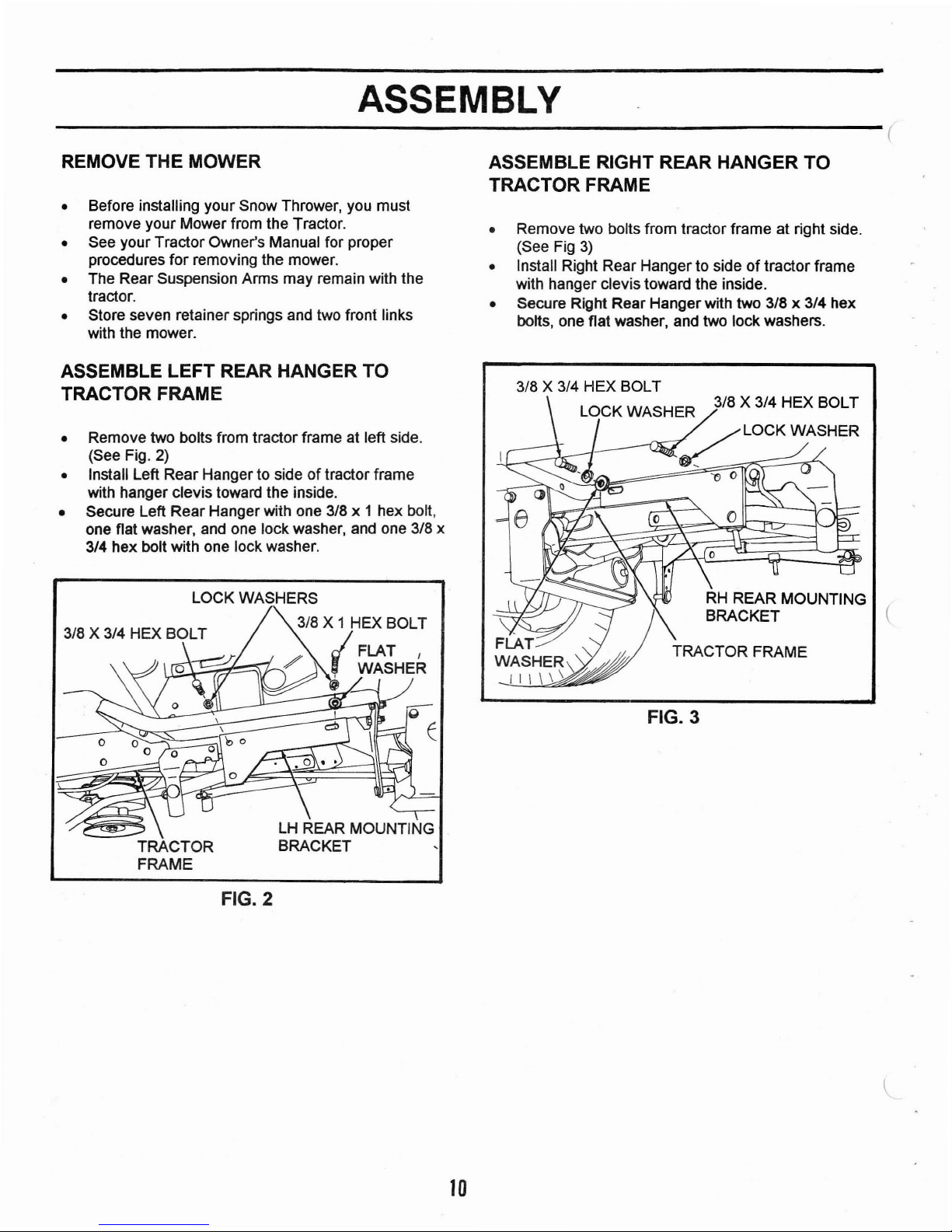
ASSEMBLE RIGHT REAR HANGER
TO
TRACTOR FRAME
• Before installing your Snow Thrower, you must
remove your Mower from the Tractor.
• See your Tractor Owner's Manual for proper
procedures for removing the mower.
• The Rear Suspension Arms may remain with the
tractor.
• Store seven retainer springs and two front links
with the mower.
• Remove two bolts from tractor frame at right side.
(See Fig
3)
• Install Right Rear Hanger to sideoftractor frame
with hanger clevis toward the inside.
• Secure Right Rear Hangerwith two
3/8 x 3/4 hex
bolts, one flat washer, and two lockwashers.
ASSEMBLE LEFT REAR HANGER TO
TRACTOR FRAME
RH
REAR MOUNTING
BRACKET (
FLAT
WASHER\
'"
I I \ \ \ \
FIG. 3
3/8 X 3/4 HEX BOLT
lOCK
WASHER 3/8 X 3/4 HEX BOLT
_
~LOCK
WASHER
'0
0
E
lH
REAR MOUNTING
BRACKET
LOCK WASHERS
3/8 X 1 HEX BOLT
..J
FLAT I
~
WASHER
TRACTOR
FRAME
Remove two bolts from tractor frame at left side.
(See Fig. 2)
Install Left Rear Hanger to side
of
tractor frame
with hanger clevis toward the inside.
Secure Left Rear Hangerwith one
3/8 x 1 hex bolt,
one flat washer, and one lock washer, and one
3/8 x
3/4 hex bolt with one lock washer.
•
•
•
FIG. 2
10
ASSEMBLY
FIG. 7
FIG.
6
FIG. 5
"
BOLT
3/8
X 1
1/4
WASHER
3/8
LOCK
s
@.
/
'--~
HEIGHT INDICATOR
"POINTE~
CRANK
ROD
SUPPORT
ANCHOR
11
MOUNTING
ANCHOR
/NYLOCK
NUT
FIG. 4
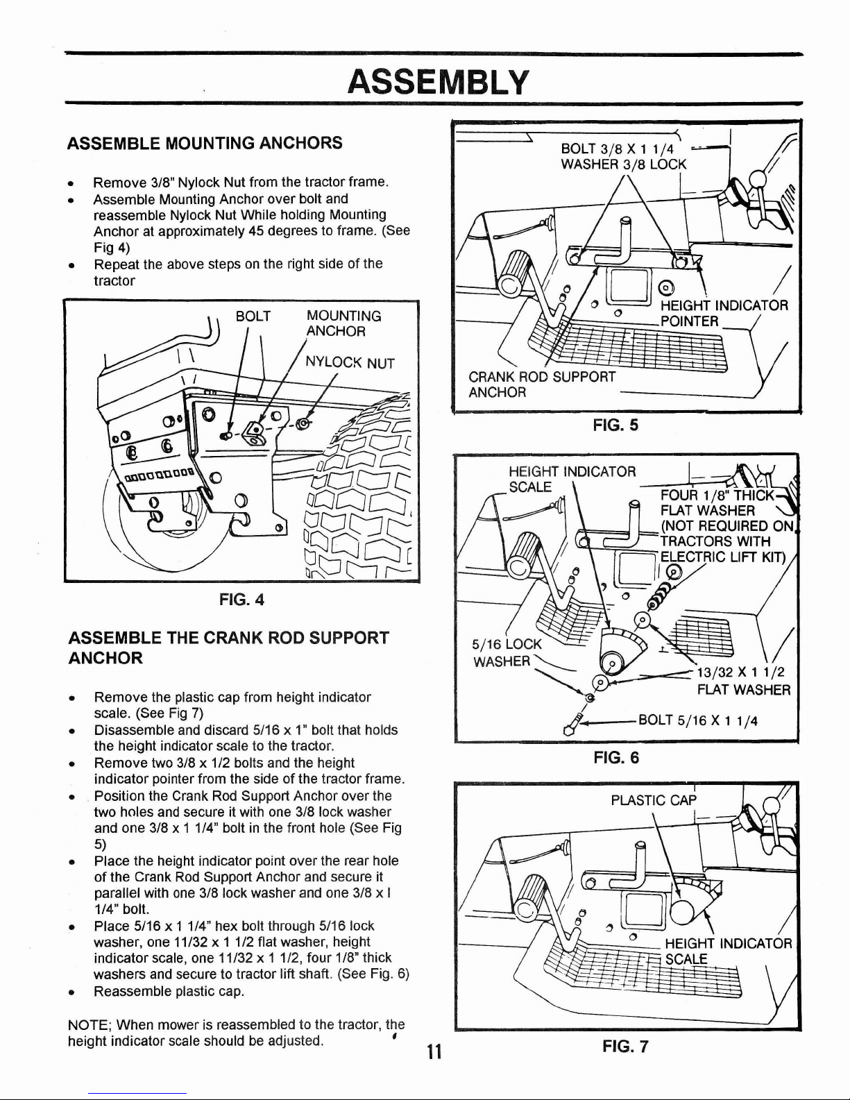
ASSEMBLE THE CRANK ROD SUPPORT
ANCHOR
• Remove the plastic cap from height indicator
scale. (See Fig
7)
• Disassemble and discard 5/16 x 1" bolt that holds
the height indicator scale to the tractor.
• Remove two 3/8 x 1/2 bolts and the height
indicator pointer from the side
of
the tractor frame.
• Position the Crank Rod Support Anchor over the
two holes
and
secure it with one 3/8 lock washer
and one 3/8 x 1 1/4" bolt
in
the front hole (See Fig
5)
• Place the height indicator point over the rear hole
of
the Crank
Rod
Support Anchor and secure it
parallel with
one
3/8 lock washer and one 3/8 x I
1/4" bolt.
• Place 5/16 x 1 1/4" hex bolt through 5/16 lock
washer, one 11/32 x 1 1/2 flat washer, height
indicatorscale, one 11/32 x 1 1/2, four 1/8" thick
washers and secure to tractor lift shaft. (See Fig.
6)
• Reassemble plastic cap.
NOTE; When mower is reassembled to the tractor, the
height indicator scale should
be
adjusted. '
• Remove 3/8" Nylock Nut from the tractor frame.
• Assemble Mounting Anchor over bolt and
reassemble Nylock Nut While holding Mounting
Anchor at approximately 45 degrees to frame. (See
Fig 4)
• Repeat the above steps
on
the right sideofthe
tractor
ASSEMBLE MOUNTING ANCHORS
 Loading...