

Craftsman 82369 Owner's Manual
Owner's Manual
AC/DC Clamp Meter
Model No.
82369
© Sears, Roebuck and Co., Hoffman Estates, IL 60179 U.S.A
www.craftsman.com 070113
Safety
Operation
Maintenance
Español
CAUTION: Read, understand and
follow Safety Rules and Operating
Instructions in this manual before
using this product.

2
TABLE OF CONTENTS
Warranty Page 3
Safety Instructions 4
Safety Symbols 5
Control and Jacks 6
Symbols and Annunciators 6
Specifications 7
Operating Instructions 11
AC Current Measurements 11
DC Current Measurements 11
AC Voltage Measurements 12
DC Voltage Measurements 12
Resistance Measurements 13
Continuity Measurements 13
Diode Testing 14
Capacitance Measurements 14
Frequency/Duty Cycle Measurements 15
Temperature Measurements 15
Auto Power Off 16
Auto/Manual Ranging 16
Data Hold 16
Backlight 16
ZERO function 16
Maintenance 17
Battery Replacement 17
Troubleshooting 18
Service and Parts 18
3
ONE YEAR FULL WARRANTY
ONE YEAR FULL WARRANTY ON CRAFTSMAN AC/DC CLAMP
METER
If this CRAFTSMAN Clamp Meter fails to give complete satisfaction within
one year from the date of purchase, RETURN IT TO THE NEAREST
SEARS STORE OR OTHER CRAFTSMAN OUTLET IN THE UNITED
STATES, and Sears will replace it, free of charge.
This warranty gives you specific legal rights, and you may also have
other rights which vary from state to state.
Sears, Roebuck and Co., Dept. 817WA, Hoffman Estates, IL 60179
For Customer Assistance Call 9am - 5pm (ET)
Monday through Friday 1-888-326-1006
WARNING: USE EXTREME CAUTION IN THE USE OF THIS
DEVICE. Improper use of this device can result in injury or
death. Follow all safeguards suggested in this manual in addition
to the normal safety precautions used in working with electrical
circuits. DO NOT service this device if you are not qualified to do
so.

4
SAFETY INSTRUCTIONS
This meter has been designed for safe use, but must be operated
with caution. The rules listed below must be carefully followed for
safe operation.
1. NEVER apply voltage or current to the meter that exceeds the
specified maximum:
Input Limits
Function
Maximum Input
V DC, V AC, Frequency, Duty Cycle
600V DC/AC
A AC, A DC
400A AC
Resistance
250V DC/AC
Capacitance
250V DC/AC
Temperature
60V DC/, 24V AC
Diode test
250V DC/AC
2. USE EXTREME CAUTION when working with high voltages
3. DO NOT measure voltage if the voltage on the "COM" input
jack exceeds 240V above earth ground
4. DO NOT measure current of circuits whose voltage is greater
than 240V above earth ground
5. NEVER connect the meter leads across a voltage source
while the function switch is in the resistance or diode mode.
Doing so can damage the meter
6. ALWAYS turn off the power and disconnect the test leads
before opening the doors to replace the fuse or batteries
7. NEVER operate the meter unless the back cover is in place
and fastened securely
5
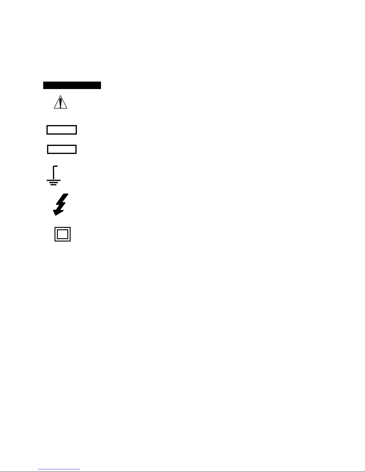
SAFETY SYMBOLS
This symbol adjacent to another symbol,
terminal or operating device indicates that the
operator must refer to an explanation in the
Operating Instructions to avoid personal injury
or damage to the meter
This WARNING symbol indicates a potentially
hazardous situation, which if not avoided, could
result in death or serious injury
This CAUTION symbol indicates a potentially
hazardous situation, which if not avoided, may
result in damage to the meter
This symbol advises the user that the
terminal(s) so marked must not be connected to
a circuit point at which the voltage, with respect
to earth ground, exceeds (in this case) 600
VAC or VDC
This symbol adjacent to one or more terminals
identifies them as being associated with ranges
that may, in normal use, be subjected to
particularly hazardous voltages. For maximum
safety, the meter and its test leads should not
be handled when these terminals are energized
This symbol indicates that a device is protected
throughout by double insulation or reinforced
insulation
WARNING
CAUTION
MAX
600V
6
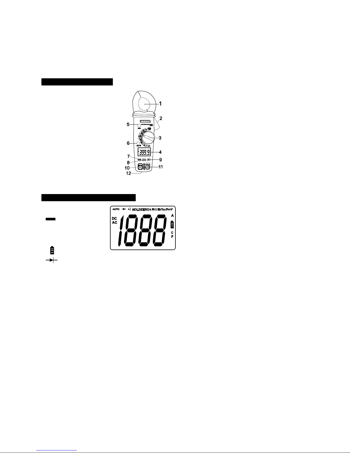
CONTROLS AND JACKS
1. Current clamp
2. Clamp Opening Trigger
3. Rotary Function Switch
4. LCD display
5. ZERO button
6. Data Hold and Backlight button
7. Mode select button
8. Range select button
9. Hz/% Duty Cycle button
10. COM input jack
11. V/Ω/Temp jack
12. Battery Cover (rear)
SYMBOLS AND ANNUNCIATORS
AC AC (alternating current)
DC DC (direct currrent)
Minus sign
AUTO AutoRange mode
ZERO ZERO mode
•))) Audible Continuity
HOLD Data Hold mode
Low Battery icon
Diode test mode M Mega
m milli Ω Ohms
V Volts °F Degrees Fahrenheit
A Amps °C Degrees Centigrade
 Loading...