

Craftsman 82351 Owner's Manual
1
2
3
4
5
6
7
Owner’s Manual
Pocket Multimeter
Model: 82351
© Sears, Roebuck and Co., Hoffman Estates, IL 60179 U.S.A.
www.craftsman.com 061906
ONE YEAR FULL WARRANTY
ONE YEAR FULL WARRANTY ON CRAFTSMAN MULTIMETER
If this CRAFTSMAN Multimeter fails to give complete satisfaction within one
year from the date of purchase, RETURN IT TO THE NEAREST SEARS
STORE OR OTHER CRAFTSMAN OUTLET IN THE UNITED STATES, and
Sears will replace it, free of charge.
This warranty gives you specific legal rights, and you may also have other
rights which vary from state to state.
Sears, Roebuck and Co., Dept. 817WA, Hoffman Estates, IL 60179
For Customer Assistance Call 9am - 5pm (ET)
Monday through Friday 1-888-326-1006
WARNING: USE EXTREME CAUTION IN THE USE OF THIS DEVICE.
Improper use of this device can result in injury or death. Follow all safeguards
suggested in this manual in addition to the normal safety precautions used in
working with electrical circuits. DO NOT service this device if you are not
qualified to do so.
SAFETY INSTRUCTIONS
This meter has been designed for safe use, but must be operated with
caution. The rules listed below must be carefully followed for safe operation.
1. NEVER apply voltage or current to the meter that exceeds the specified
maximum:
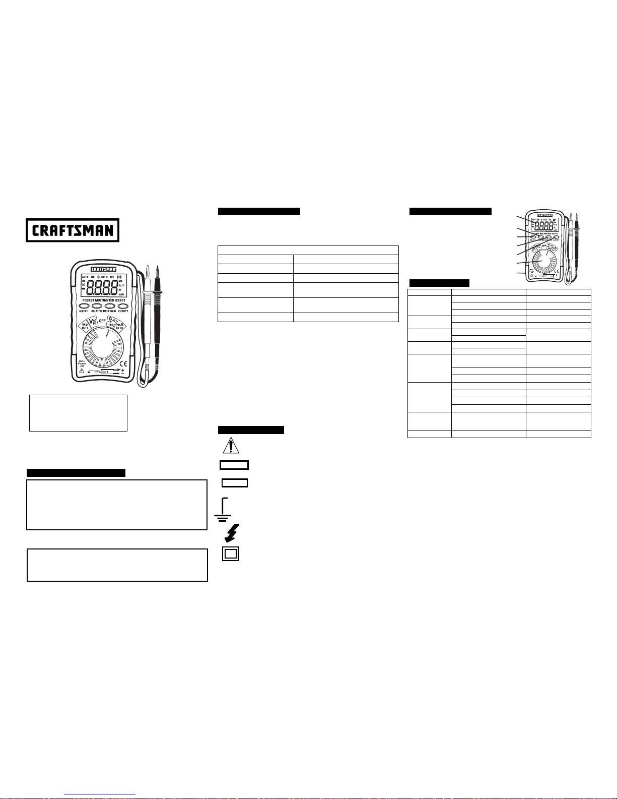
Input Protection Limits
Function Maximum Input
V DC or V AC 600V AC and DC
mA AC/DC 500mA DC/AC
A AC/DC
10A DC/AC (for 30 seconds max. every 15
minutes)
Resistance, Diode Test,
Continuity
250V DC/AC
Temperature 250V DC/AC
2. USE EXTREME CAUTION when working with high voltages.
3. DO NOT measure voltage if the voltage on the "COM" input jack exceeds
600V above earth ground.
4. NEVER connect the meter leads across a voltage source while the
function switch is in the current, resistance, or diode mode. Doing so can
damage the meter.
5. ALWAYS discharge filter capacitors in power supplies and disconnect the
power when making resistance or diode tests.
6. ALWAYS turn off power and disconnect test leads before opening the
covers to replace the fuse or battery.
7. NEVER operate the meter unless the back cover and the battery and fuse
covers are in place and fastened securely.
8. If the equipment is used in a manner not specified by the manufacturer,
the protection provided by the equipment may be impaired.
SAFETY SYMBOLS
This symbol adjacent to another symbol, terminal or operating
device indicates that the operator must refer to an explanation
in the Operating Instructions to avoid personal injury or damage
to the meter.
This WARNING symbol indicates a potentially hazardous
situation, which if not avoided, could result in death or serious
injury.
This CAUTION symbol indicates a potentially hazardous
situation, which if not avoided, may result damage to the
product.
This symbol advises the user that the terminal(s) so marked
must not be connected to a circuit point at which the voltage
with respect to earth ground exceeds 600V.
This symbol adjacent to one or more terminals identifies them
as being associated with ranges that may, in normal use, be
subjected to particularly hazardous voltages. For maximum
safety, the meter and its test leads should not be handled when
these terminals are energized.
This symbol indicates that a device is protected throughout by
double insulation or reinforced insulation.
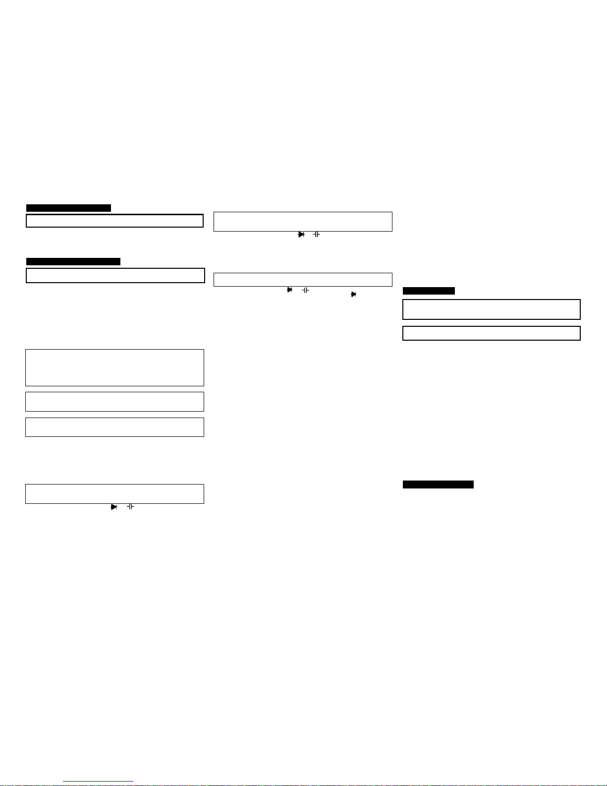
CONTROLS AND JACKS
1. 3 3/4 Digit (4000 count)
2. RELATIVE button
3. SELECT button
4. DATA HOLD button
5. Hz/DUTY button
6. Function switch
7. Rubber holster
SPECIFICATIONS
Function Range Accuracy
400.0mV ±(0.7% reading + 3 digits)
4.000V, 40.00V, ±(1.0% reading + 3 digits)
DC Voltage
400.0V,500V ±(1.3% reading + 3 digits)
4.000V, 40.00V ±(1.0% reading + 10 digits) AC Voltage
(40-400Hz)
400.0V, 500V ±(2.3% reading + 5 digits)
40.00mA DC Current
400.0mA
±(2.0% reading + 5 digits)
40.00mA AC Current
(50-60 Hz)
400.0mA
±(2.5% reading + 10 digits)
400.0, 4.000k, 40.00k,
400.0k
±(2.0% reading + 5 digits)
4.000M ±(5.0% reading + 5 digits)
Resistance
40.00M ±(10.0% reading + 5 digits)
4.000nF ±(5.0% reading + 0.3nF)
40.00nF ±(5.0% reading + 30 digits)
400.0nF ±(3.0% reading + 15 digits)
Capacitance
4.000F, 40.00F, 200.0F
(10.0% reading + 15 digits)
Frequency 9.999Hz, 99.99Hz, 999.9Hz,
9.999kHz, 99.99kHz,
999.9kHz, 10MHz
±(2.0% reading + 5 digits)
Duty Cycle 0.1-99% ±(2.0% reading + 5 digits)
Max input voltage 500V AC/DC
Input Sensitivity, 10Vrms min. <9.999KHz
(Frequency Ranges) 40Vrms min. >99.99KHz
Diode Test Test current 1mA max., open circuit voltage of 1.5V
typical
Continuity Check Audible signal if the resistance is < 60
Display 4000 count 3 digit LCD
Over range indication LCD displays “OL”
Polarity Minus (-) sign for negative polarity.
Low Battery Indication “BAT” symbol indicates low battery condition.
Battery CR2032 3V Lithium
Operating Temperature 41
o
F to 104oF (5oC to 40oC)
Storage Temperature 14
o
F to 122oF (-10oC to 50oC)
Operating Humidity Max 80% up to 87ºF (31ºC) decreasing linearly to
50% at 104ºF (40ºC)
Storage Humidity <80%
Operating Altitude 7000ft. (2000meters) maximum.
Weight 1.7oz (50g)
Size 4.25x2.2x.5” (108x56x11.5mm)
Safety For indoor use and in accordance with the
requirements for double insulation to IEC1010-1
(1995): EN61010-1 (1995) Overvoltage Category II
600V, Pollution Degree 2. UL, CE Approved
• Safety
• Operation
• Maintenance
• Español
CAUTION: Read, understand and
follow Safety Rules and Operating
Instructions in this manual before
using this product.
WARNING
CAUTION
MAX
600V
BATTERY INSTALLATION
WARNING: To avoid electric shock, disconnect the test leads from any
source of voltage before removing the battery cover.
1. Remove the rubber holster (if in place)
2. Remove Philips head screw and lift off the rear housing of the meter.
3. Replace old battery with fresh CR2032 type button battery.
4. Replace the rear cover and secure the screw.
OPERATING INSTRUCTIONS
WARNING: Risk of electrocution. High-voltage circuits, both AC and DC, are
very dangerous and should be measured with great care.
1. ALWAYS turn the function switch to the OFF position when the meter is not
in use.
2. Press the HOLD button to freeze a displayed reading
NOTE: On some low AC and DC voltage ranges, with the test leads not
connected to a device, the display may show a random, changing reading.
This is normal and is caused by the high-input sensitivity. The reading will
stabilize and give a proper measurement when connected to a circuit.
AC OR DC VOLTAGE MEASUREMENT
WARNING: Risk of Electrocution. The probe tips may not be long enough
to contact the live parts inside some 240V o utlets for applianc es because
the contacts are reces sed deep in the outl ets. As a res ult, the r eading may
show 0 volts when the outlet actua lly has voltage o n it. Make s ure the pr ob e
tips are touching the metal contac ts inside the out let before assuming that
no voltage is present.
CAUTION: Do not measure AC voltages if a motor on the circu it is
being switched ON or OF F. Large voltage surges may occur that can
damage the meter.
CAUTION: Do not measure DC voltages if a motor on the circu it is
being switched ON or OF F. Large voltage surges may occur that can
damage the meter.
1. Set the function switch to the “V
AC/DC” position
2. Press the SELECT button to select AC or DC voltage measurement
3. Touch the test probe tips to the circuit under test. Be sure to observe the
correct polarity (red lead to positive, black lead to negative).
4. Read the voltage on the display
RESISTANCE/CONTINUITY MEASUREMENT
WARNING: To avoid electric shock, disconnect power to the unit under
test and discharge all capacitors before taking any resistance
measurements. Remove the batteries and unplug the line cords.
1. Set the function switch to the “ •))) ” position.
2. Connect the test leads to the circuit to be measured.
3. Read the value on the display.
4. For Continuity tests, press the SELECT button until the “•)))“ symbol
appears in the display.
5. If the resistance is less than 60 ohms, an audible tone will sound.
CAPACITANCE MEASUREMENT
WARNING: To avoid electric shock, disconnect power to the unit under
test and discharge all capacitors before taking any capacitance
measurements. Remove the batteries and unplug the line cords.
1. Set the function switch to the “ •))) ” position.
2. Press the SELECT button until “nF” appears in the display.
3. Press the RELATIVE button to zero the display
4. Connect the test leads to the capacitor to be measured.
5. Read the value on the display.
DIODE TEST
WARNING: To avoid electric sho ck, do not test any diode that has
voltage on it.
1. Set the function switch to “ •))) “position.
2. Press the SELECT button once to enter Diode Test. The “ “ symbol will
appear in the display.
3. Touch the test probe tips to the diode or semiconductor junction you wish to
test. Note the meter reading.
4. Touch the test probes to the diode under test. Forward voltage will
typically indicate 0.400 to 0.700V. Reverse voltage will indicate
“OL”. Shorted devices will indicate near 0V and an open device will
indicate “OL” in both po lar ities.
AC OR DC CURRENT MEASUREMENT
1. Set the function switch to the “mA AC/DC” position.
2. Press the SELECT button to measure AC or DC mA.
3. Remove power from the circuit under test and open the circuit at the point
where you wish to measure current.
4. Touch the black test probe tip to the negative side of the circuit and touch
the red test probe tip to the positive side of the circuit.
5. Apply power to the circuit.
6. Read the value on the display
FREQUENCY/DUTY CYCLE MEASUREMENT
1. Set the function switch to the “HZ/DUTY” position.
2. Press the Hz/DUTY button once to display Duty Cycle %. Pressing the
button again will toggle the display to frequency (Hz).
3. Touch the test probe tips to the circuit under test. Be sure to observe the
correct polarity (red lead to positive, black lead to negative).
4. Read the value on the display.
RELATIVE BUTTON
The relative measurement feature allows you to make measurements relative
to a stored reference value. A reference voltage can be stored and
measurements made in comparison to that value. The displayed value is the
difference between the reference value and the measured value.
1. Perform the measurement as described in the operating instructions.
2. Press the RELATIVE button to store the reading in the display and the "REL"
indicator will appear on the display.
3. The display will now indicate the difference between the stored value and
the measured value.
4. Press the RELATIVE button to exit the relative mode.
Note: The Relative function does not operate in the Frequency function.
DATA HOLD BUTTON
The Data Hold function allows the meter to “freeze” a measurement for later
reference
1. Press the “DATA HOLD” button to “freeze” the display, the “HOLD” indicator
will appear.
2. Press the “DATA HOLD” button to return to normal operation.
AUTO POWER OFF
1. To save power, the display automatically turns off in 30 minutes.
2. Press the SELECT button to turn display back on.
3. To cancel Auto Power Off, set the function switch to the off position. Hold
down the SELECT button and turn the function switch to the desired position
and release the SELECT button after 3 seconds.
MAINTENANCE
WARNING: To avoid electric shock, disconnect the test leads from any
source of voltage before removing the back cover or the battery or fuse
covers.
WARNING: To avoid electric shock, do not operate your meter until the
battery and fuse covers are in place and fastened securely.
This MultiMeter is designed to provide years of dependable service, if the
following care instructions are performed:
1. KEEP THE METER DRY. If it gets wet, dry it immediately.
2. USE AND STORE THE METER IN NORMAL TEMPERATURES.
Temperature extremes can shorten the life of the electronic parts and
distort or melt plastic parts.
3. HANDLE THE METER GENTLY AND CAREFULLY. Dropping it can
damage the electronic parts or the case.
4. KEEP THE METER CLEAN. Wipe the case occasionally with a damp
cloth. DO NOT use chemicals, cleaning solvents, or detergents.
5. USE ONLY FRESH BATTERIES OF THE RECOMMENDED SIZE AND
TYPE. Remove old or weak batteries so they do not leak and damage the
unit.
6. IF THE METER IS TO BE STORED FOR A LONG PERIOD OF TIME,
the batteries should be removed to prevent damage to the unit.
UL LISTED
The UL mark does not indicate that this product has been evaluated for the
accuracy of its readings.
TROUBLESHOOTING
There may be times when your meter does not operate properly. Here are
some common problems that you may have and some easy solutions to them.
Meter Does Not Operate:
1. Always read all the instructions in this manual before use.
2. Check to be sure the battery is properly installed.
3. Check to be sure the battery is good.
4. If the battery is good and the meter still doesn’t operate, check to be sure
that both ends of the fuse are properly installed.
If You Do Not Understand How the Meter Works :
1. Purchase “Multitesters and Their Use for Electrical Testing”,
(Item No. 82303).
2. Call our Customer Service Line 1-888-326-1006.
 Loading...