

Craftsman 82344 Owner's Manual
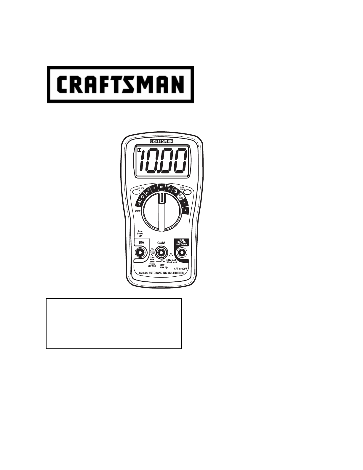
Owner’s Manual
Auto-Ranging MultiMeter
Model 82344
CAUTION: Read, understand and
follow Safety Rules and Operating
Instructions in this manual before
using this product.
© Sears, Roebuck and Co., Hoffman Estates, IL 60179 U.S.A.
www.craftsman.com 08080 6
• Safety
• Operation
• Maint enance
• Español

TABLE OF CONTENTS
Page
Warranty 3
Safety Instructions 4
Safety Symbols 5
Control and Jacks 6
Symb ols and Ann unc i ators 6
Specifications 7
Battery Installation 10
Operating Instructions 11
DC Voltage Me as ur e m ents 11
AC Voltage Measurem en ts 12
AC/DC Current Measurements 13
Resis t a nc e Me as ure me nts 14
Capacitance Measurements 14
Freq u enc y Me as ur e m en ts 15
Te m pera ture Me as ur ement s 14
Cont inui ty Tes t 15
Diode Test 16
Data Hold 16
Low Bat ter y 16
Auto-Ranging 16
Auto-Power Off 16
Maintenance 17
Replac ing th e Batteri es 18
Replac ing th e Fus e 18
Troubleshooting 19
Servic e and Parts 19
2
ONE YEAR FULL WARRANTY
ONE YEAR FULL WARRANTY ON CRAFTSMAN MULTIMETER
If this CRAFTSMAN Multimeter fails to give complete satisfaction within
one year from the date of purchase, RETURN IT TO THE NEAREST
SEARS STORE OR OTHER CRAFTSMAN OUTLET IN THE UNITED
STATES, and Sears will replace it, free of charge.
This warranty gives you specific legal rights, and you may also have
other rights which vary from state to state.
Sears, Roebuck and Co., Dept. 817WA, Hoffman Estates, IL 60179
For Customer Assistance Call 9am - 5pm (ET)
Monday through Friday 1-888-326-1006
WARNING: USE EXTREME CAUTION IN THE USE OF THIS
DEVICE. Improper use of this device can result in injury or
death. Follow all safeguards suggested in this manual in
addition to the normal safety precautions used in work ing with
electrical circuits. DO NOT service this device if you are not
quali fi ed t o d o so.
3
SAFETY INSTRUCTION S
This m eter has been designed for saf e us e, but mus t be
operated with caution. The rules listed below must be carefully
followed for safe operation.
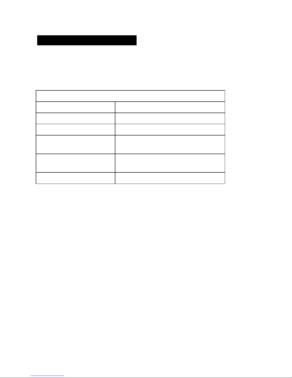
1. NEVER apply voltage or current to the meter that exceeds
the specified maximum:
Input Protection Limits
Function Maximum Input
V DC, V AC 600V DC and 600V AC
mA AC/DC 200mA AC/DC
A AC/DC 10A AC/DC (for 15 seconds max.
every 15 minutes)
Resistan ce, Diode Test,
500V AC/DC
Continuity
Frequency 250V AC/DC
2. USE EXTREME CAUTION whe n working with h igh
voltages.
3. DO NOT measure voltage if the volt age on the "COM" input
jack exceeds 600V above earth ground.
4. NEVER connect the meter leads across a voltage source
while the function switch is in the current, resistance, or
diode mod e. Doi ng so can damage the meter.
5. ALWAYS discharge filter capacitors in power supplies and
disc on nec t th e pow er when making resis ta nc e or d io de
tests.
6. ALWAYS turn off power and disconnect test leads before
opening the covers to replace the fuse or battery.
7. NEVER oper a te th e meter u nles s t he bac k cov er is in plac e
and fasten ed securel y.
8. If the equipment is use d in a ma n ner not spec if i e d by th e
manu fac turer , the pr ot ec t io n pr ov i de d by th e eq ui p me nt
may be imp aired.
4
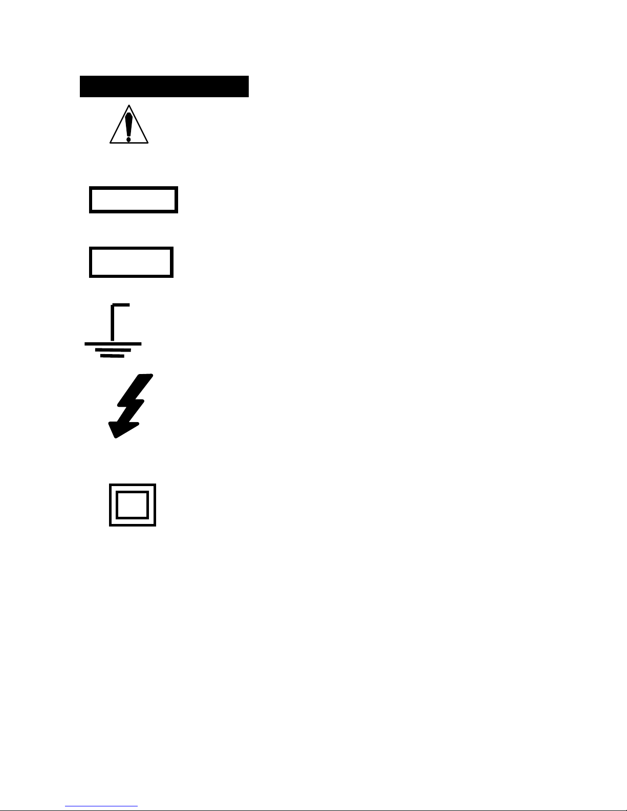
SAF E T Y SYMB O LS
This sy m bo l ad jac e nt t o an ot her symb ol,
terminal or operating device indicates that
the operat or mus t r ef er to an exp la nati on in
the Operating Instructions to avoid personal
injury or damage to t he meter.
This WARNING symbol indicates a
WARNING
poten tially hazardous si t u ati on , whic h if not
avoided, could result in death or serious
injury.
CAUTION
MAX
600V
This CAUTION symbol indicates a
poten tially hazardous si t u ati on , whic h if not
avoided, may result damage to the product.
This symbol advises the user that the
terminal(s) so marked must not be
connected to a circuit point at which the
voltage with respect to earth ground
exc eeds 60 0V .
This sy m bo l ad jac e nt to on e or mo re
terminals identifies them as being
associated with ranges that may, in normal
use, be sub jec t ed t o part icul arly haz ardous
voltages. For maximum safety, the meter
and its test leads should not be handled
when these terminals are energized.
This symbol indicates th at a device is
protected throughout by double insulation or
reinforced ins ul ati on.
5
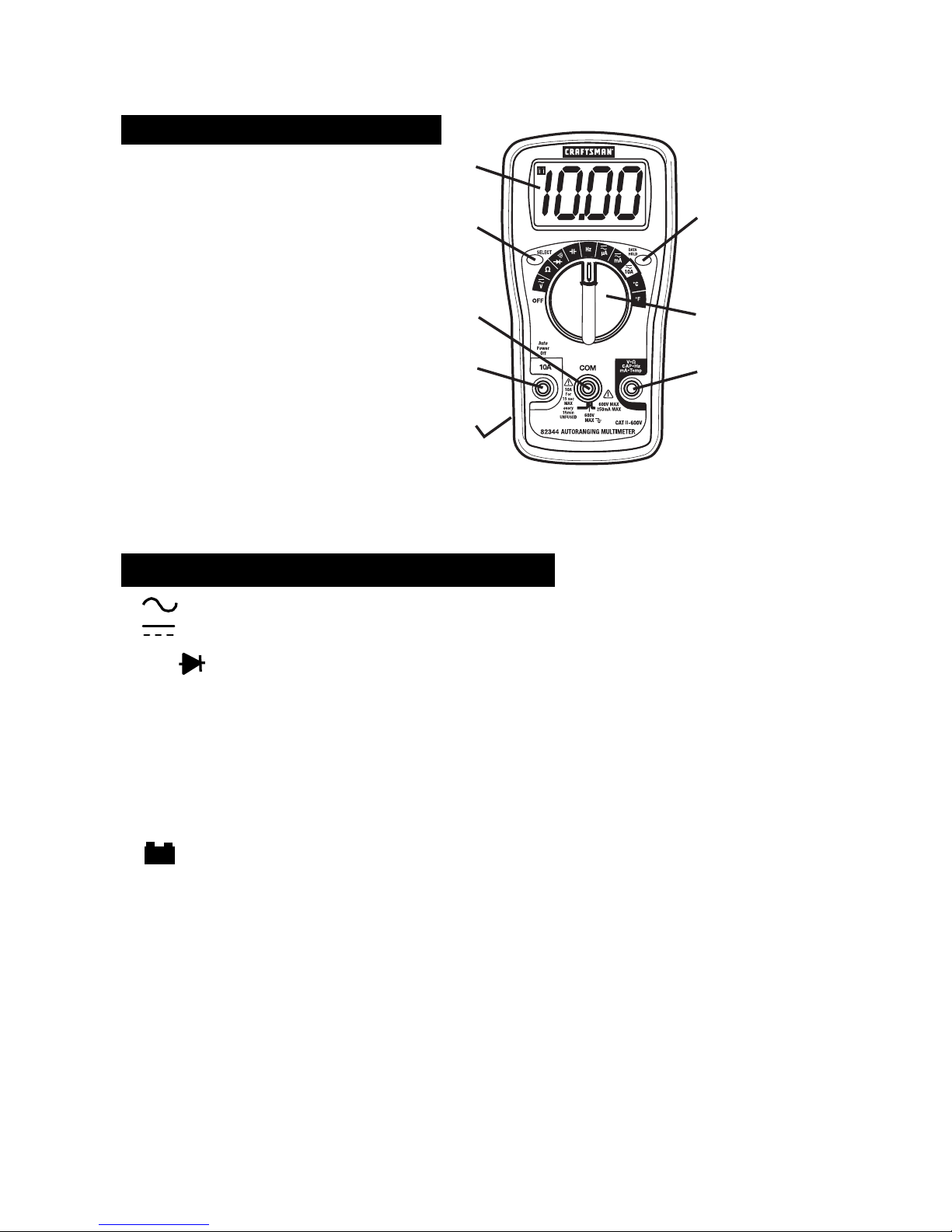
CONTROLS AND JACKS
1. LCD Dis play
1
2. D ATA HO LD but ton
3. SELECT but ton
3
4. Func tion sw itch
5. Positive input jack
6. COM jack
6
7. 10A jack
8. R ub ber boot
7
8
Note: Tilt stand and bat tery
acce ss
is on the rear of unit.
SYMBOLS AND ANNUNCIATORS
AC (voltage)
2
4
5
DC (direct current or voltage)
•))) Continuity and Diode test
mV, V millivolt, volt (voltage)
, k, M ohm, kilohm, megohm (resistance)
mA , A milliamp, Amp (cur rent )
nF, uF nanof arads, mic r ofara ds (capacitanc e)
Hz Hertz (frequency)
º
F, ºC Degrees Fahrenheit, Centigrade (temperature)
º
Low battery
H Display hold
AUTO Autoranging
6
 Loading...