

Craftsman 82339 Owner's Manual
Owner's Manual
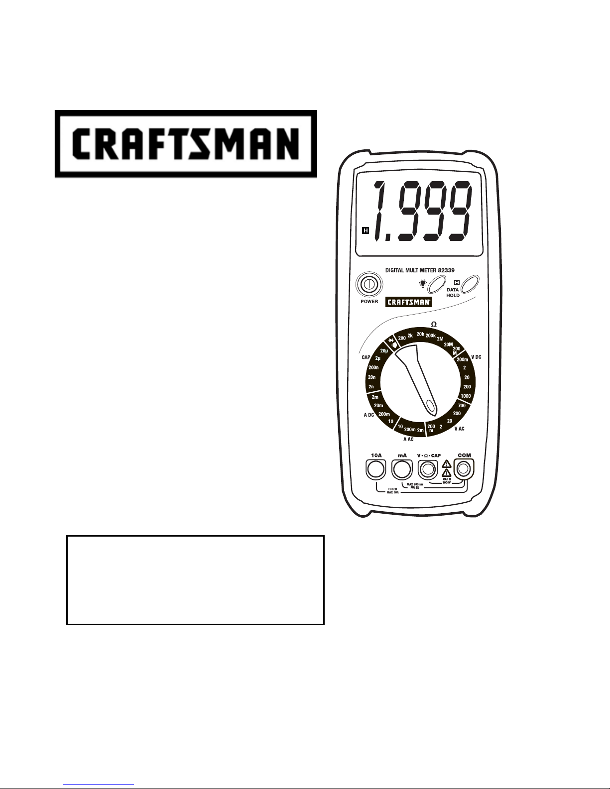
Digital MultiMeter
Model No.
82339
CAUTION: Read, understand and
follow Safety Rules and Operating
Instructions in this manual before
using this product.
Sears, Roebuck and Co., Hoffman Estates, IL 60179
www.craftsman.com 061906
• Safety
• Operation
• Maintenance
• Español

TABLE OF CONTENTS
Page
Warranty 3
Safety Instructions 4
Safety Symbols 5
Control and Jacks 6
Symbols and Annunciators 6
Specifications 7
Battery Installation 9
Operating Instructions 10
Data Hold 10
Backlight 10
Range Indicator 10
Input Shutters 10
DC Voltage Measurements 11
AC Voltage Measurements 11
DC Current Measurements 12
AC Current Measurements 12
Resistance Measurements 13
Continuity Check 13
Diode Test 14
Capacitance Measurements 14
Maintenance 15
Replacing the Battery 15
Replacing the Fuses 16
Troubleshooting 17
Service and Parts 17
2

ONE YEAR FULL WARRANTY
ONE YEAR FULL WARRANTY ON CRAFTSMAN MANUAL RANGING
MULTIMETER
If this CRAFTSMAN Manual Ranging MultiMeter fails to give complete
satisfaction within one year from the date of purchase, RETURN IT TO
THE NEAREST SEARS STORE OR OTHER CRAFTSMAN OUTLET IN
THE UNITED STATES, and Sears will replace it, free of charge.
If this CRAFTSMAN Manual Ranging MultiMeter is used for commercial
or rental purposes, this warranty applies for 90 days from the date of
purchase.
This warranty gives you specific legal rights, and you may also have
other rights which vary from state to state
Sears, Roebuck and Co., Dept. 817WA, Hoffman Estates, IL 60179
For Customer Assistance Call 9am-5 PM (EST)
Monday through Friday 1-888-326-1006
WARNING: USE EXTREME CAUTION IN THE USE OF THIS DEVICE.
Improper use of this device can result in injury or death. Follow all
safeguards suggested in this manual in addition to the normal safety
precautions used in working with electrical circuits. DO NOT service this
device if you are not qualified to do so.
3
SAFETY INSTRUCTIONS
This meter has been designed for safe use, but must be operated with
caution. The rules listed below must be carefully followed for safe operation.
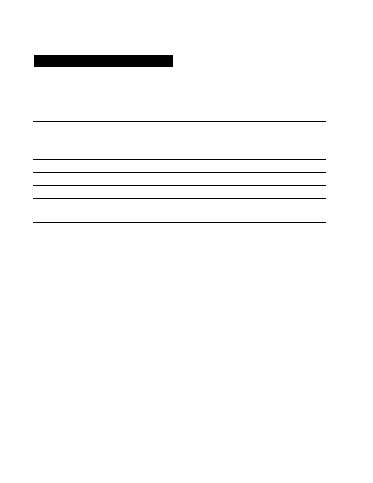
1. NEVER apply voltage or current to the meter that exceeds the
specified maximum:
Input Limits
Function Maximum Input
V DC 200mV range 250V DC or AC
V DC/V AC >200mV ranges 1000V DC or 700V AC
mA DC/AC 200mA DC/AC
10A DC/AC 10A DC/AC
Resistance, Capacitance,
250V DC/AC
Diode test, Continuity
2. USE EXTREME CAUTION when working with high voltages.
3. DO NOT measure voltage if the voltage on the "COM" input jack
exceeds 1000V above earth ground.
4. NEVER connect the meter leads across a voltage source while the
function switch is in the current, resistance, or diode mode. Doing so
can damage the meter.
5. ALWAYS discharge filter capacitors in power supplies and disconnect
the power when making resistance or diode tests.
6. ALWAYS turn off the power and disconnect the test leads before
opening the doors to replace the fuse or battery.
7. NEVER operate the meter unless the back cover and the battery and
fuse doors are in place and fastened securely.
4
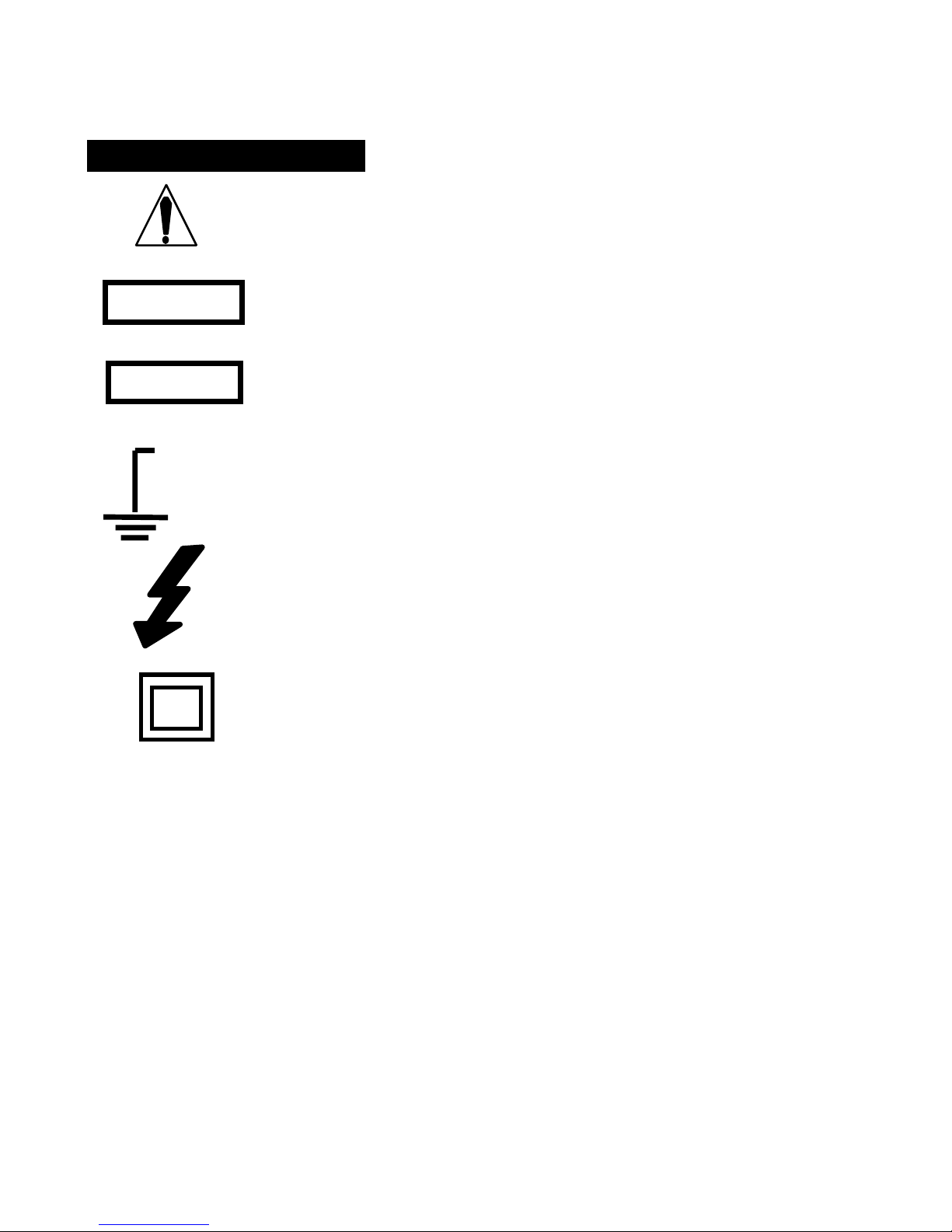
SAFETY SYMBOLS
This symbol adjacent to another symbol, terminal or
operating device indicates that the operator must refer
to an explanation in the Operating Instructions to avoid
personal injury or damage to the meter.
WARNING
CAUTION
MAX
1000V
This WARNING symbol indicates a potentially
hazardous situation, which if not avoided, could result
in death or serious injury.
This CAUTION symbol indicates a potentially
hazardous situation, which if not avoided, may result
damage to the product.
This symbol advises the user that the terminal(s) so
marked must not be connected to a circuit point at
which the voltage with respect to earth ground
exceeds (in this case) 1000 VAC or VDC.
This symbol adjacent to one or more terminals
identifies them as being associated with ranges that
may, in normal use, be subjected to particularly
hazardous voltages. For maximum safety, the meter
and its test leads should not be handled when these
terminals are energized.
Double Insulation
5
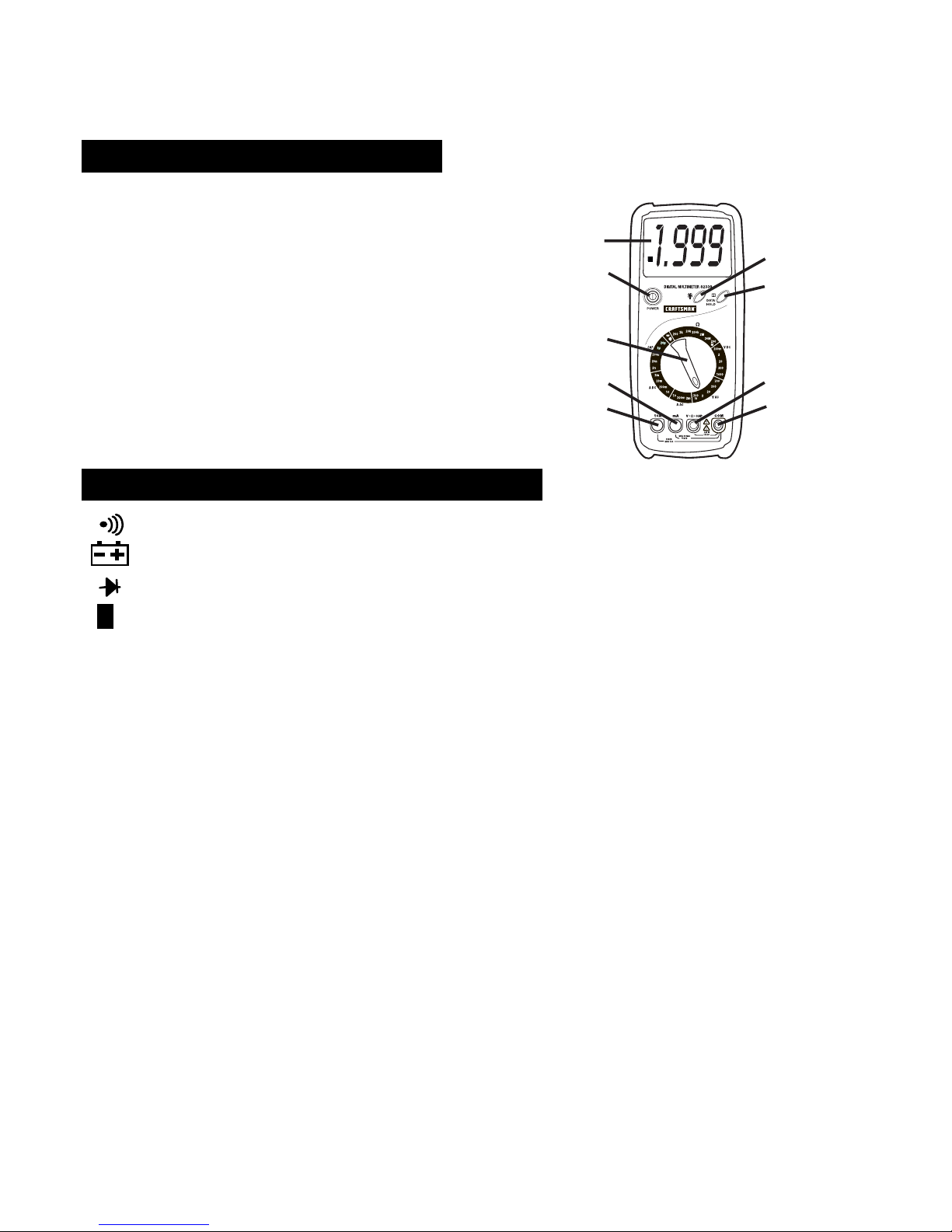
CONTROLS AND JACKS
1. 2000 count Liquid Crystal Display
2. Power switch
3. Function Switch
4. mA current input jack
5. 10A current input jack
6. Backlight pushbutton.
7. Data Hold pushbutton
8. Voltage, resistance and capacitance
positive input jack
9. Common negative input jack
SYMBOLS AND ANNUNCIATORS
Continuity
Low Battery
Diode
1
2
3
4
5
6
7
8
9
H Data Hold
AC Alternating Current or Voltage
DC Direct Current or Voltage
mV, V millivolt, volt (voltage)
!! k!! M! ohm, kilohm, megohm (resistance)
mA, A milliamp, Amp (current)
nF, uF nanofarads, microfarads (capacitance)
6
 Loading...