

Craftsman 82337 Owner's Manual
Owner's Ma nual
Manual Ranging
Multimeter
Model No.
82337
CAUTION: Read, understand and
follow Safety Rules and Operating
Instructions in this manual before
using this product.
© Sears, Roebuck and Co., Hoffman Estates, IL 60179 U.S.A.
www.craftsman.com 061906
• Safety
• Operation
• Maint enance
• Español

TABLE OF CONTENTS
Warranty Page 3
Safety Instructions 4
Safety Symbols 5
Contro l and Jacks 6
Symbols and Annunciators 6
Specifications 7
Battery Installation 9
Operating Instructions 10
DC Voltage Measurements 10
AC Voltage Measurements 11
DC Current Measurements 12
AC Current Measurements 13
Resis t a nc e Me as ureme nt s 14
Continuity Measurements 15
Diode T es t 15
Temp er a ture Meas ureme nts 16
Display Backlight 17
Battery Check 17
Data Hold 17
Auto Power O ff 17
Low Bat ter y In dic at i o n 17
Blown Fuse Indication 17
Wrong C o nn ec t i on In dic ation 17
Maintenance 18
Battery Replacement 19
Fuse Replacement 19
Troubleshooting 21
Servic e and Parts 21
2
ONE YEAR FULL WARRANTY
ONE YEAR FULL WARRANTY ON CRAFTSMAN PROFESSIONAL
MULTIMETER
If this CRAFTSMAN Professional Multimeter fails to give complete
satisfaction within one year from the date of purchase, RETURN IT TO
THE NEAREST SEARS STORE OR OTHER CRAFTSMAN OUTLET IN
THE UNITED STATES, and Sears will replace it, free of charge.
This warranty gives you specific legal rights, and you may also have
other rights which vary from state to state.
Sears, Roebuck and Co., Dept. 817WA, Hoffman Estates, IL 60179
For Customer Assistance Call 9am - 5pm (ET)
Monday through Friday 1-888-326-1006
WARNING: USE EXTREME CAUTION IN THE USE OF THIS
DEVICE. Improper use of this device can result in injury or
death. Follow all safeguards suggested in this manual in addition
to the normal safety precautions used in working with electrical
circuits. DO NOT service this device if you are not qualified to do
so.
3
SAFETY INSTRUC TI ONS
This m eter has bee n des i gn ed for safe us e, bu t mus t be operated
with caution. The rules listed below must be carefully followed for
safe op eration.
1. NEVER apply voltage or current to the meter that exceeds the
spec ifi e d max imum :
Input Lim its
Function Maximum Input
V DC or V AC 600V DC/AC, 200Vrms on 200mV
range
mA AC/DC 200mA 250V fast acting fuse
A AC/DC 20A 250V fast acting fuse(30
sec onds m ax every 1 5 minutes )
Resistance, Diode Test,
Continuity
Temperature 60V DC/24V AC
2. USE EXTREME CAUTION when working with high voltages
250Vrms for 15 sec max
3. DO NOT measure voltage if the voltage on the "CO M" input
jack exceeds 600V above earth ground
4. DO NOT measure current of circuits whose voltage is greater
than 60 0V ab ov e ear t h ground
5. NEVER connect the meter leads across a voltage source
while the function switch is in the resistance or diode mode.
Doing so can damage the meter
6. ALWAYS turn off the power and dis c onnec t the tes t le ads
before opening the cover to replace the battery
7. NEVER oper a te th e meter unless the bac k cov er is in place
and fastened secure ly
4
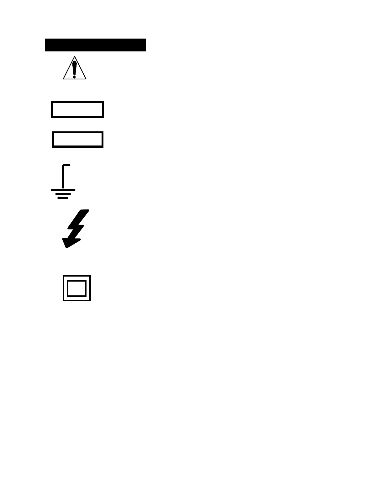
SAF E T Y SYMBOLS
This sy m bo l ad jac e nt t o an ot her symb ol ,
terminal or operating device indicates that the
operator must refer to an explanation in the
Oper ati ng Instruc t i ons to av o id per sonal in jur y
or damage to t he meter.
WARNING
CAUTION
MAX
600V
This WARNING sy mbol indic a tes a pot en t ia lly
hazardous situation, which if not avoided,
could result in death or serious injury.
This CAUTION sym b ol in dic a t es a pot ent ia lly
hazardous situation, which if not avoided, may
result damage to the product.
This symbol advises the user that the
terminal(s) so marked must not be connected
to a circuit point at which the voltage with
respect to earth ground exceeds (in this case)
600 VAC or VDC.
This sy m bo l ad jac e nt to on e or more ter mi na ls
identi fies them as bein g asso ciated with
ranges that may, in normal use, be subjected
to particularly hazardous voltages. For
maximum safety, the me ter a nd its test leads
shou ld n ot be ha ndled whe n t h es e termina ls
are energize d.
This symbol indicates tha t a device is
protected throughout by double insulation or
reinforced insul ati on .
5
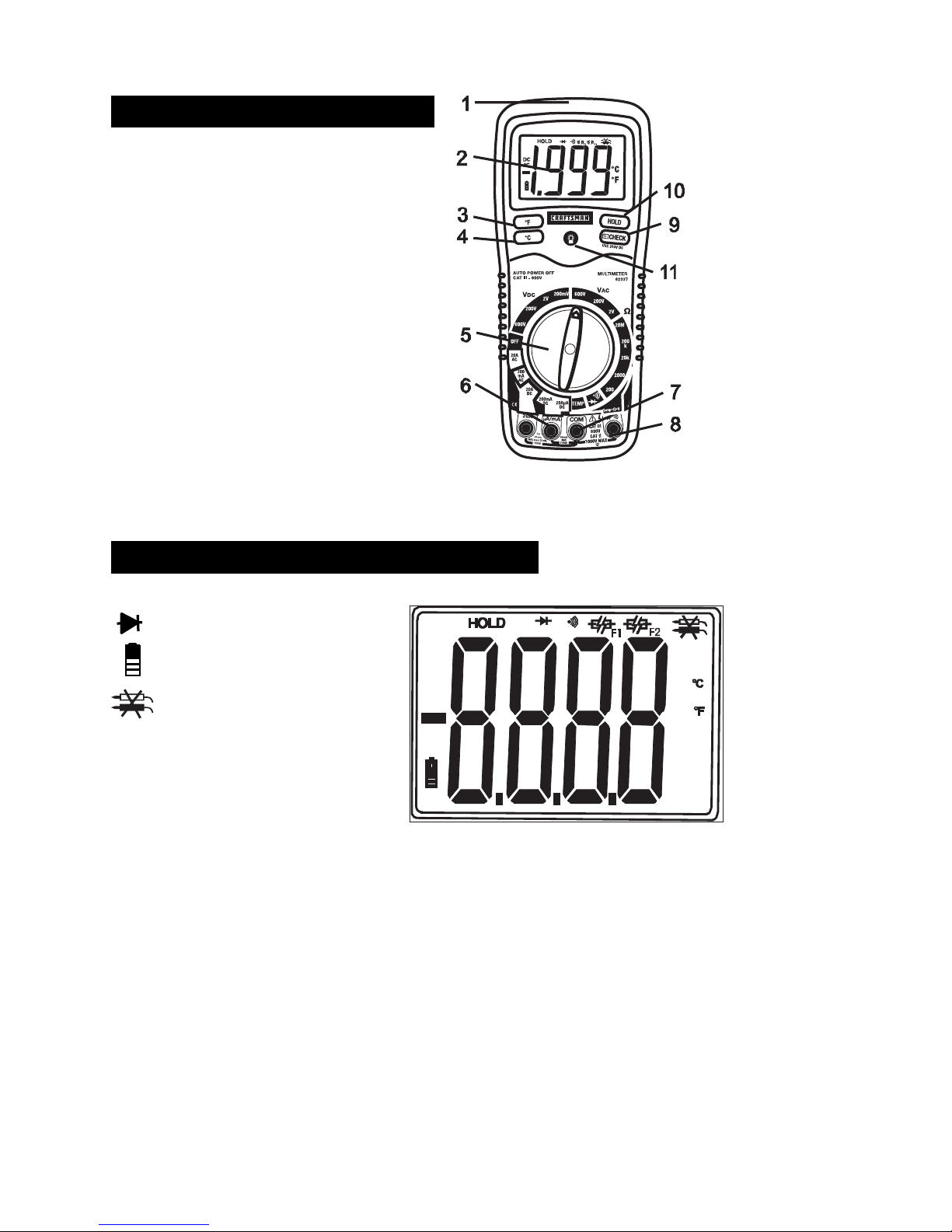
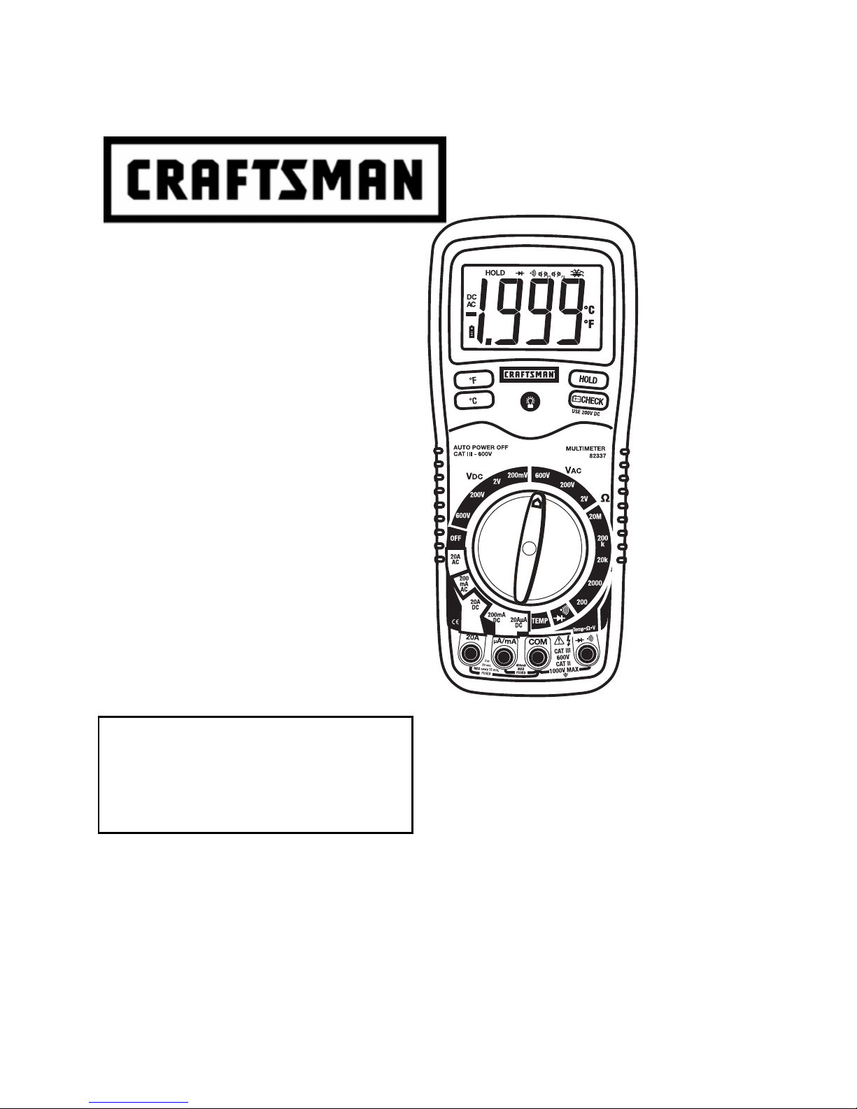
CONTROLS AND JACKS
1. Rubber holster
2. 2000 c ou nt LC D dis play
3. Degrees F button
4. Degrees C button
5. Function switch
6. mA, uA and A input jacks
7. COM input jack
8. Positive input j ack
9. Battery check button
10. H old button
11. Bac klig ht butt on
Note: Tilt stand and battery compartment are on rear of unit.
SYMBOLS AND ANNUNCIATORS
•))) Continuity
Diode t es t
Battery status
Test lead connection
error
-6
micro (10
m milli (10
k kilo (10
M mega (10
) (amps)
-3
) (volts, amps) A Amps
3
) (ohm s)
6
) (ohms)
V Volts
AC Alternating current
DC Direct current
Ohms
HOLD Data hold
ºF Degrees Fahrenheit
ºC Degrees Centigrade
6
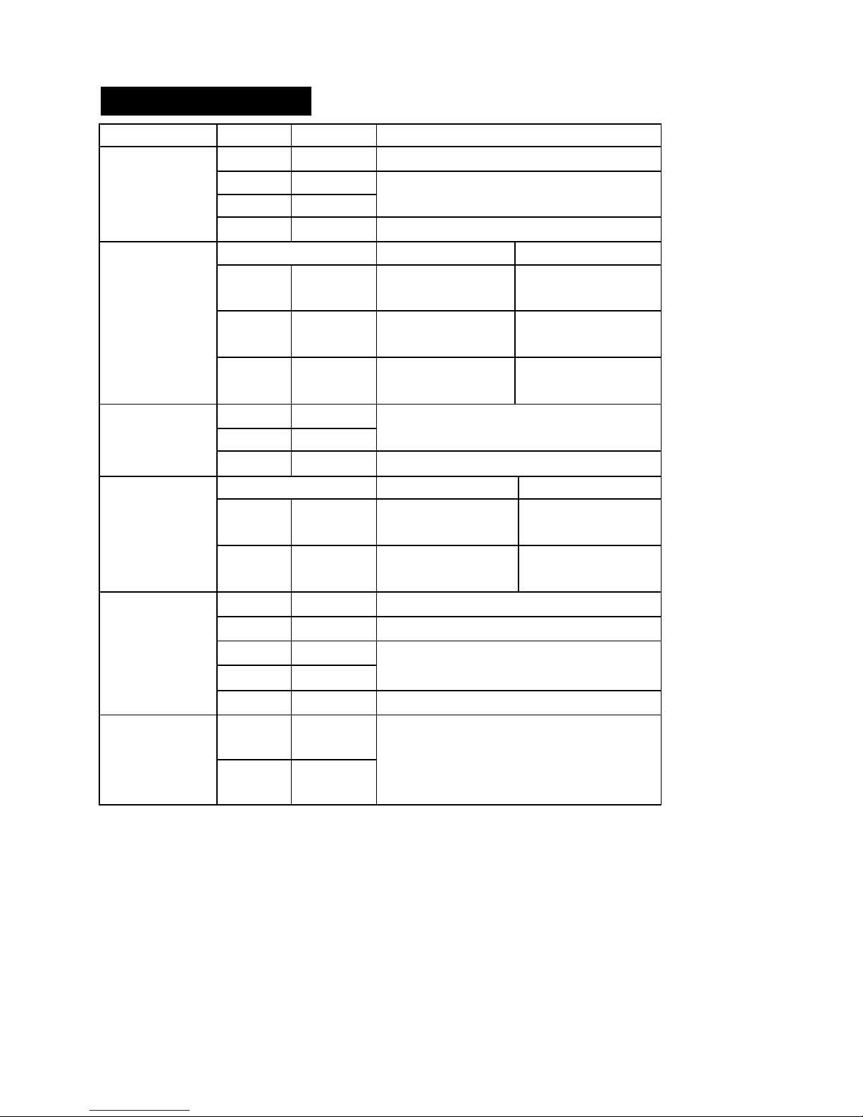
SPECIFICATIONS
Function Range Resolution
DC Voltage
(V DC)
200mV 0.1mV ±(0.3% reading + 2 digits)
2V 0.001V
200V 0.1V
600V 1V ±(0.8% reading + 2 digits)
Accuracy
±(0.5% reading + 2 digits)
AC Voltage
(V AC)
DC Current
(A DC)
AC Current
(A AC)
Resistance
50 to 400H z 400Hz to 1kHz
2V 0.001V ±(1.0% reading
+6 digits
200V 0.1V ±(1.5% reading
+6 digits
600V 1V ±(2.0% reading
+6 digits
200µA 0.1µA
±(1.5% reading + 3 digits)
±(2.0% reading
+ 8 digits
±(2.5% reading
+8 digits
±(3.0% reading
+8 digits
200mA 0.1mA
20A 0.01A ±(2.5% reading + 3 digits)
50 to 400H z 400Hz to 1kHz
200mA 0.1mA ±(1.8% reading
+8 digits
20A 0.01A ±(3.0% reading
+8 digits )
±(2.5% reading
+10 digits)
±(3.5% reading
+10 digits)
200 0.1 ±(0. 8% reading +4 di gits )
2000 1 ±(0.8% re ad in g +2 di git s )
20k 0.01k
±(1.0% re ad in g +2 di git s )
200k 0.1k
20M 0.01M
-4 to
1382ºF
-20 to
750ºC
NOTE: Accuracy specifications consist of two elements:
• (% reading) – This is the accuracy of the measurement circuit.
• (+ digits) – This is the accuracy of the analog to digital
converter.
NOTE: Accuracy is sta ted at 65
than 75% RH.
1ºF Temperature
1ºC
±(2.0% re ad in g +5 di git s )
±(3.0% re ad in g +3 di git s )
(meter only, probe accuracy not
included)
o
F to 83oF (18oC to 28oC) and less
7
 Loading...