

Craftsman 82312 Owner's Manual

Owner's Manual
Mini Multimeter
with Non-Contact
Voltage Detector
(NCV)
Model No.
82312
CAUTION: Read, understand and
follow Safety Rules and Operating
Instructions in this manual before
using this product.
• Safety
• Operation
• Maintenance
• EspafioI
O Sears, Roebuck and Co., Hoffman Estates, IL 60179 U.S.A.
www.craftsman.com 071006
IP'._:| II :[o] |o[o] _I / :1_i I_
Warranty ............................................................................................ 3
Safety Instructions ............................................................................ 4
Safety Symbols ................................................................................. 5
Controls And Jacks ........................................................................... 6
Symbols ............................................................................................ 7
Specifications .................................................................................... 8
Battery Installation .......................................................................... 11
Operating Instructions .................................................................... 12
Non-Contact AC Voltage Detector ............................................. 13
AC Voltage Measurements ......................................................... 14
DC Voltage Measurements ......................................................... 15
Battery Voltage Test ................................................................... 16
AC / DC Current Measurements ................................................. 17
Resistance Measurements ......................................................... 18
Continuity Check ......................................................................... 19
Diode Test ................................................................................... 20
Maintenance ................................................................................... 21
Low Battery Indication .................................................................... 21
Battery Replacement ...................................................................... 22
Replacing The Fuses ...................................................................... 22
Troubleshooting .............................................................................. 24
Service And Parts ........................................................................... 24

D]_I=li'd =!':1t,I =1II I IlVlVl:lt,]tJ':l _i I_
ONE YEAR FULL WARRANTY ON CRAFTSMAN MULTIMETER
If this CRAFTSMAN Multimeter fails to give complete satisfaction within
one year from the date of purchase, RETURN IT TO THE NEAREST
SEARS STORE OR OTHER CRAFTSMAN OUTLET IN THE UNITED
STATES, and Sears wiii replace it, free of charge.
This warranty gives you specific legal rights, and you may also have
other rights which vary from state to state.
Sears, Roebuck and Co., Dept. 817WA, Hoffman Estates, IL 60179
For Customer Assistance Call 9am - 5pm (ET)
Monday through Friday 1-888-326-1006
WARNING: USE EXTREME CAUTION IN THE USE OF THIS
DEVICE. Improper use of this device can result in injury or
death, Follow all safeguards suggested in this manual in addition
to the normal safety precautions used in working with electrical
circuits, DO NOT service this device if you are not qualified to do
so,
This meter has been designed for safe use, but must be
operated with caution. The rules listed below must be carefully
followed for safe operation.
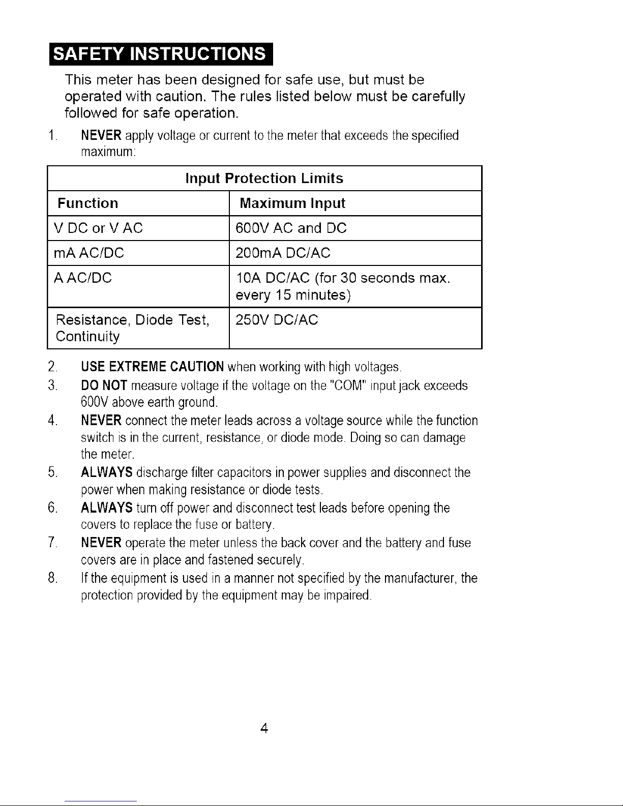
NEVERapplyvoltage orcurrenttothe meterthatexceedsthe specified
maximum:
Input Protection Limits
Function Maximum Input
V DC or V AC 600V AC and DC
mA AC/DC 200mA DC/AC
AAC/DC 10A DC/AC (for 30 seconds max.
every 15 minutes)
Resistance, Diode Test, 250V DC/AC
Continuity
2. USEEXTREMECAUTIONwhenworkingwithhighvoltages.
3. DONOTmeasurevoltageif thevoltageonthe"COM" inputjackexceeds
600V aboveearthground.
4. NEVERconnectthe meterleadsacrossa voltagesourcewhilethefunction
switch is inthe current,resistance,ordiodemode. Doingsocandamage
the meter.
5. ALWAYS dischargefiltercapacitorsinpowersuppliesanddisconnectthe
powerwhenmakingresistanceordiodetests.
6. ALWAYS turnoff powerand disconnecttest leadsbeforeopeningthe
coversto replacethefuse orbattery.
7. NEVERoperatethemeterunlessthebackcoverandthe batteryandfuse
coversarein placeandfastenedsecurely.
8. Iftheequipmentisusedin a mannernot specifiedby the manufacturer,the
protectionprovidedby the equipmentmaybeimpaired.
+.*I_1:11Ik'dl,.'b'd_v+I:[o] I!_
L WARNING ]
!cAOT'°NI
r MAX
600V
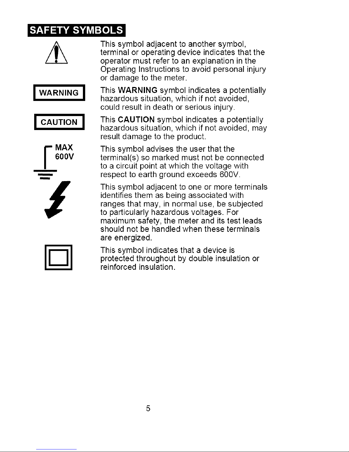
This symbol adjacent to another symbol,
terminal or operating device indicates that the
operator must refer to an explanation in the
Operating Instructions to avoid personal injury
or damage to the meter.
This WARNING symbol indicates a potentially
hazardous situation, which if not avoided,
could result in death or serious injury.
This CAUTION symbol indicates a potentially
hazardous situation, which if not avoided, may
result damage to the product.
This symbol advises the user that the
terminal(s) so marked must not be connected
to a circuit point at which the voltage with
respect to earth ground exceeds 600V.
This symbol adjacent to one or more terminals
identifies them as being associated with
ranges that may, in normal use, be subjected
to particularly hazardous voltages. For
maximum safety, the meter and its test leads
should not be handled when these terminals
are energized.
This symbol indicates that a device is
protected throughout by double insulation or
reinforced insulation.
_o] _i / _To]iF.']r_*l_Ie]PF_*To_[(_
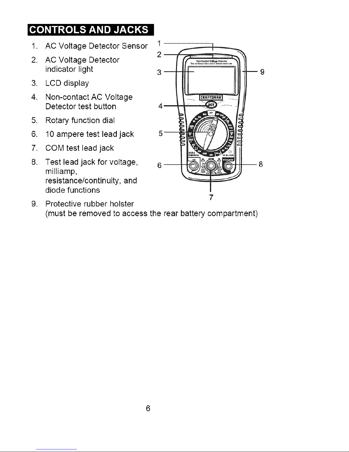
1. AC Voltage Detector Sensor 1
2. AC Voltage Detector z
indicator light 3
3. LCD display
4. Non-contact AC Voltage
Detector test button 4
5,
6.
7.
8.
Rotary function dial
10 ampere test lead jack
COM test lead jack
Test lead jack for voltage,
milliamp,
resistance/contin uity, and
diode functions
7
Protective rubber holster
(must be removed to access the rear battery compartment)
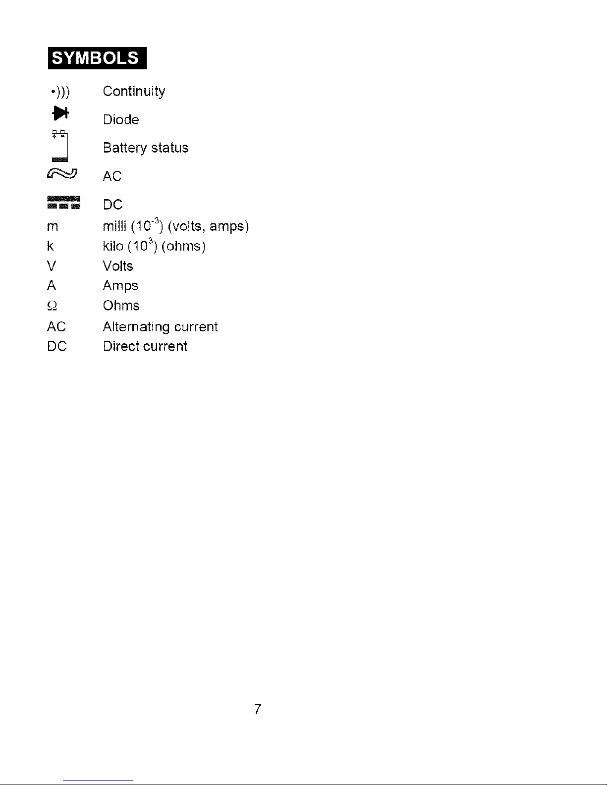
[(,.-._"d_vjI-[e] _-.]
.)))
mmm
m
k
V
A
£-)
AC
DC
Continuity
Diode
Battery status
AC
DC
milli (10 -3) (volts, amps)
kilo (10 3) (ohms)
Volts
Amps
Ohms
Alternating current
Direct current
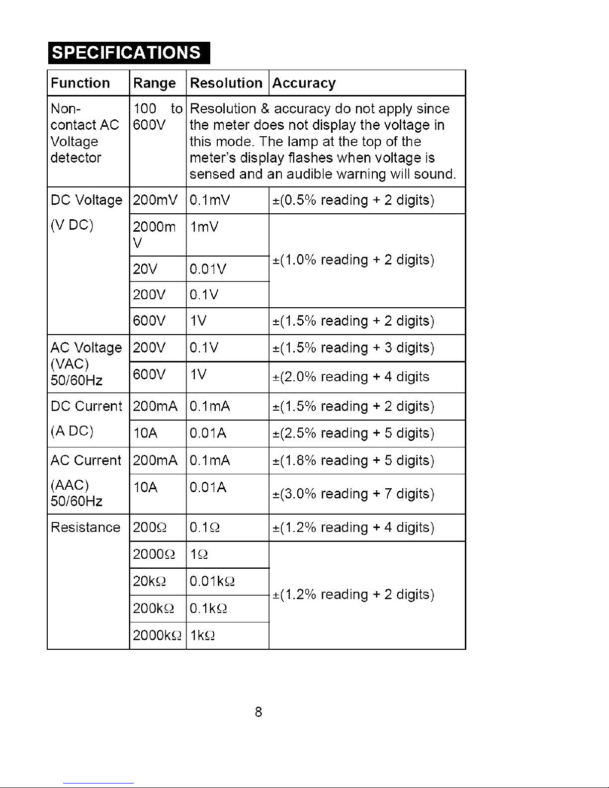
_'.,1_[l! IiI [___1t [.] __
Function
Non-
contact AC
Voltage
detector
Range Resolution Accuracy
100 to Resolution & accuracy do not apply since
600V the meter does not display the voltage in
this mode. The lamp at the top of the
meter's display flashes when voltage is
sensed and an audible warning will sound.
DC Voltage 200mV
(V DC) 2000m
V
20V 0.01V
200V 0.1V
600V 1V
AC Voltage 200V 0.1V
(VAC)
50/60Hz 600V 1V
DC Current 200mA 0.1mA
(A DC) 10A 0.01A
ACCurrent 200mA 0.1mA
(AAC) 10A 0.01A
50/60Hz
Resistance 200£-2 0.1£-2
2000£-2 1£-2
20k£-2 0.01k£-2
200k£-2 0.1k£-2
2000k£-2 1k£-2
0.1mV _+(0.5% reading + 2 digits)
lmV
_+(1.0% reading + 2 digits)
_+(1.5% reading + 2 digits)
_+(1.5% reading + 3 digits)
_+(2.0% reading + 4 digits
_+(1.5% reading + 2 digits)
_+(2.5% reading + 5 digits)
_+(1.8% reading + 5 digits)
_+(3.0% reading + 7 digits)
_+(1.2% reading + 4 digits)
_+(1.2% reading + 2 digits)
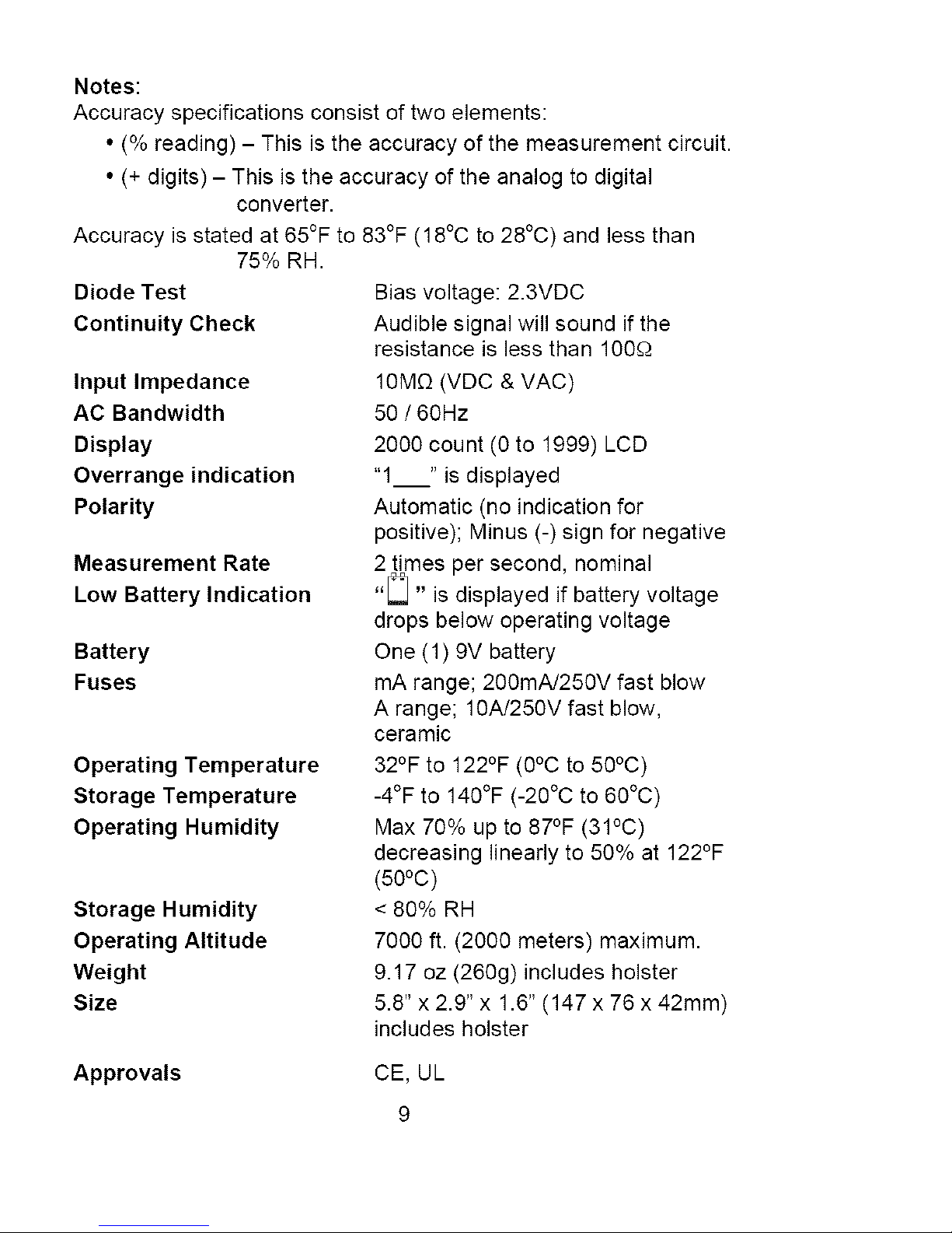
Notes:
Accuracyspecificationsconsistoftwoelements:
•(%reading)- Thisistheaccuracyofthemeasurementcircuit.
•(+digits)- Thisistheaccuracyoftheanalogtodigital
converter.
Accuracyisstatedat65°Fto83°F(18°Cto28°C)andlessthan
75%RH.
DiodeTest
ContinuityCheck
Input Impedance
AC Bandwidth
Display
Overrange indication
Polarity
Measurement Rate
Low Battery Indication
Battery
Fuses
Operating Temperature
Storage Temperature
Operating Humidity
Storage Humidity
Operating Altitude
Weight
Size
Bias voltage: 2.3VDC
Audible signal will sound if the
resistance is less than 100£-._
10MC2(VDC & VAC)
50 ! 60Hz
2000 count (0 to 1999) LCD
"1 " is displayed
Automatic (no indication for
positive); Minus (-) sign for negative
2 times per second, nominal
r_
"LI " is displayed if battery voltage
drops below operating voltage
One (1) 9V battery
mA range; 200mA/250V fast blow
A range; 10A/250V fast blow,
ceramic
32°F to 122°F (0°C to 50°C)
-4°F to 140°F (-20°C to 60°C)
Max 70% up to 87°F (31°C)
decreasing linearly to 50% at 122°F
(50°C)
< 80% RH
7000 ft. (2000 meters) maximum.
9.17 oz (260g) includes holster
5.8" x 2.9" x 1.6" (147 x 76 x 42mm)
includes holster
Approvals
CE, UL
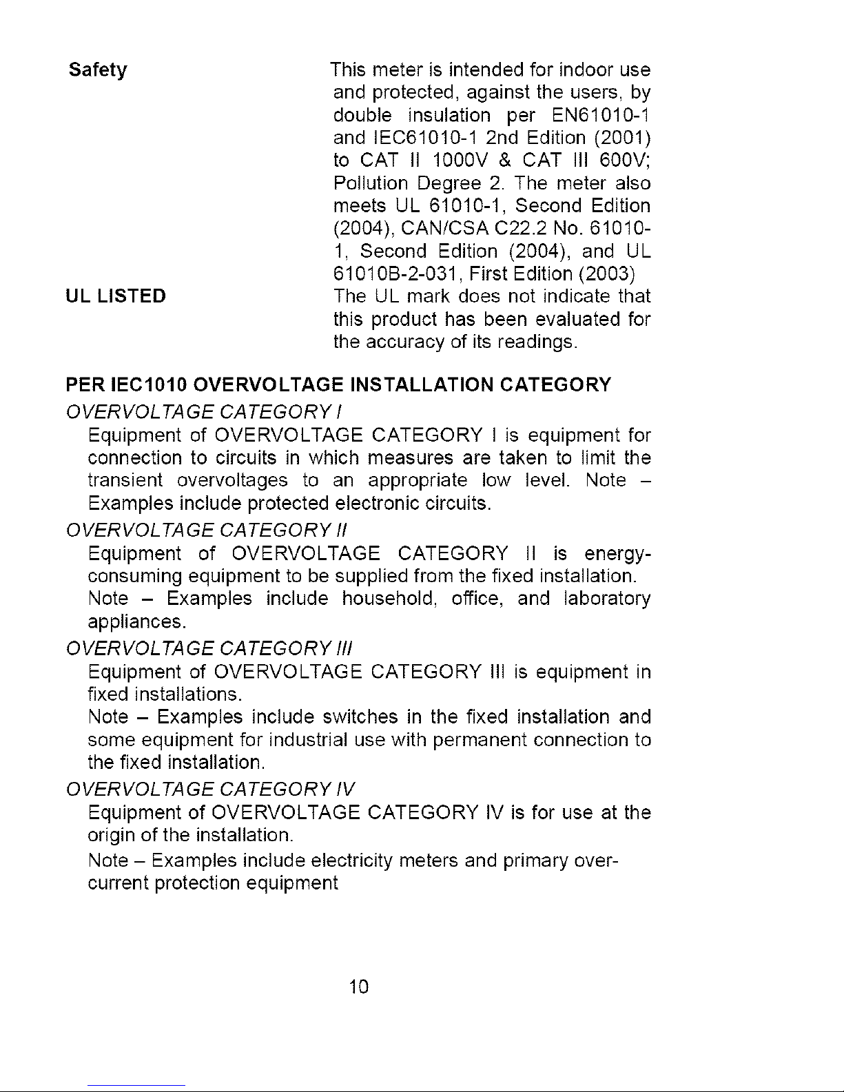
Safety
ULLISTED
Thismeterisintendedforindooruse
andprotected,againsttheusers,by
doubleinsulationperEN61010-1
andIEC61010-12ndEdition(2001)
toCATII1O00V&CATIII600V;
PollutionDegree2.Themeteralso
meetsUL61010-1,SecondEdition
(2004),CAN/CSAC22.2No.61010-
1,SecondEdition(2004),andUL
61010B-2-031,FirstEdition(2003)
TheULmarkdoesnotindicatethat
thisproducthasbeenevaluatedfor
theaccuracyofitsreadings.
PER IEC1010 OVERVOLTAGE INSTALLATION CATEGORY
OVERVOL TAGE CATEGORY I
Equipment of OVERVOLTAGE CATEGORY I is equipment for
connection to circuits in which measures are taken to limit the
transient overvoltages to an appropriate low level. Note -
Examples include protected electronic circuits.
OVERVOL TAGE CATEGORY II
Equipment of OVERVOLTAGE CATEGORY II is energy-
consuming equipment to be supplied from the fixed installation.
Note - Examples include household, office, and laboratory
appliances.
OVERVOL TAGE CATEGORY III
Equipment of OVERVOLTAGE CATEGORY III is equipment in
fixed installations.
Note - Examples include switches in the fixed installation and
some equipment for industrial use with permanent connection to
the fixed installation.
OVERVOL TAGE CATEGORY IV
Equipment of OVERVOLTAGE CATEGORY IV is for use at the
origin of the installation.
Note - Examples include electricity meters and primary over-
current protection equipment
10
I WARNING: To avoid electric shock, disconnect the test leadsfrom an)/source of voltage before removing the batter)/cover. I
1. Disconnect the test leads from the meter.
2. Remove the rear battery cover by removing the two screws
using a Phillips head screwdriver.
3. Insert the battery into battery clips, observing the correct
polarity.
4. Put the battery cover back in place and secure with the two
screws.
WARNING: To avoid electric shock, do not operate the meter |
until the battery cover is in place and fastened securely.
]
NOTE: If your meter does not work properly, check the fuses and
batteries to make sure that they are still good and that they
are properly inserted.
11
IWARNING:Riskofelectrocution.High-voltagecircuits,bothACI
and DC, are very dangerous and should be measured with great
I
care.
NOTE: On some low AC and DC voltage ranges, with the test
leads not connected to a device, the display may show a
random, changing reading. This is normal and is caused by
the high-input sensitivity. The reading will stabilize and give
a proper measurement when connected to a circuit.
12
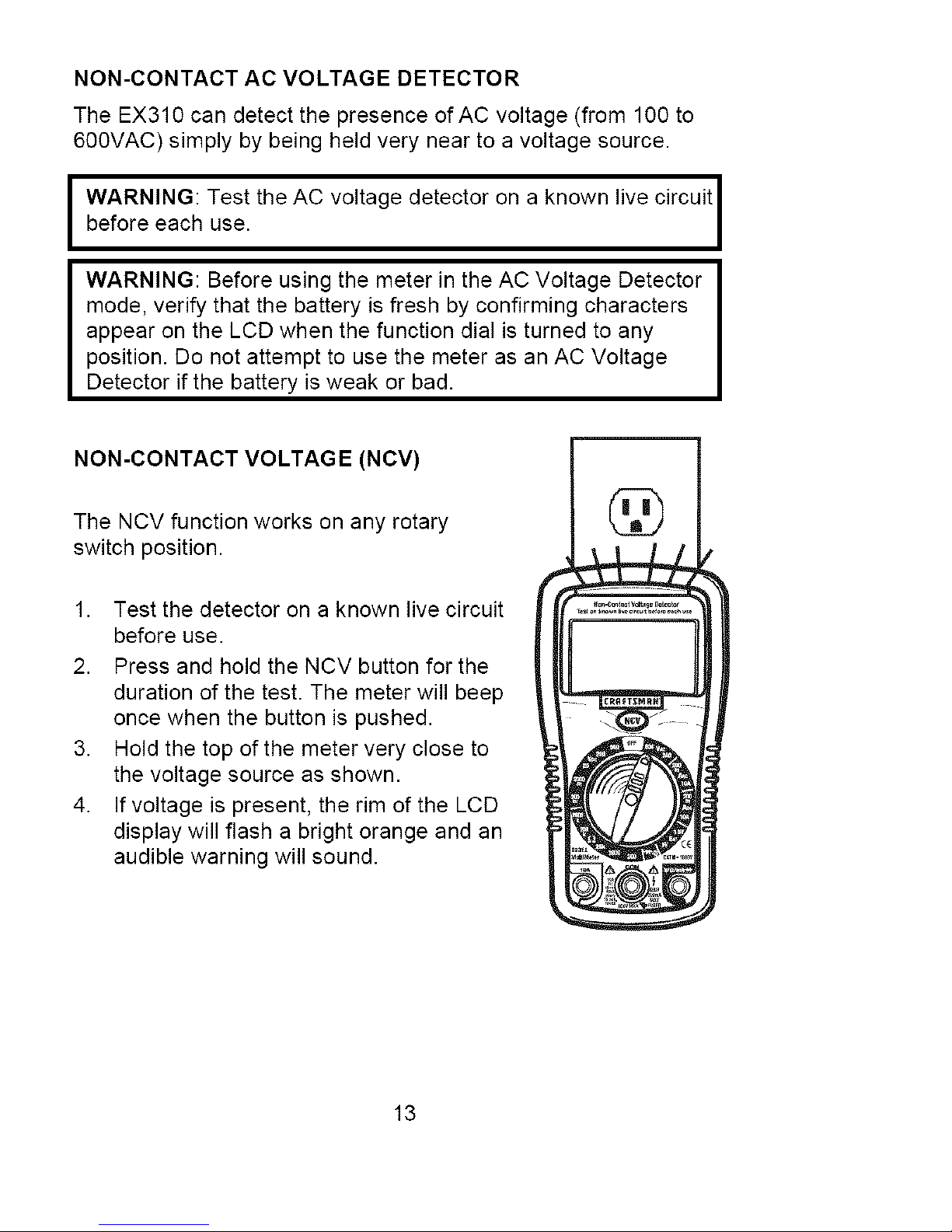
NON-CONTACTACVOLTAGEDETECTOR
TheEX310candetectthepresenceofACvoltage(from100to
600VAC)simplybybeingheldveryneartoavoltagesource.
WARNING:TesttheACvoltagedetectoronaknownlivecircuit
beforeeachuse.
WARNING:BeforeusingthemeterintheACVoltageDetector
mode,verifythatthebatteryisfreshbyconfirmingcharacters
appearontheLCDwhenthefunctiondialisturnedtoany
position.DonotattempttousethemeterasanACVoltage
Detectorifthebatteryisweakorbad.
NON-CONTACTVOLTAGE(NCV)
TheNCVfunctionworksonanyrotary
switchposition.
1. Testthedetectoronaknownlivecircuit
beforeuse.
2. PressandholdtheNCVbuttonforthe
durationofthetest.Themeterwillbeep
oncewhenthebuttonispushed.
3. Holdthetopofthemeterverycloseto
thevoltagesourceasshown.
4. Ifvoltageispresent,therimoftheLCD
displaywillflashabrightorangeandan
audiblewarning will sound.
@
13
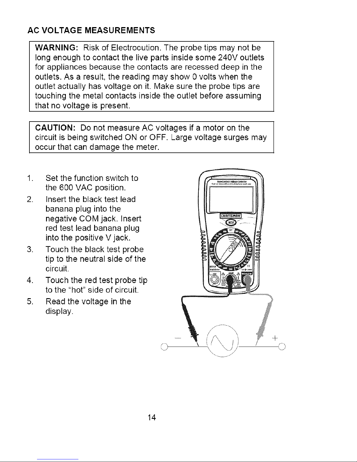
AC VOLTAGE MEASUREMENTS
WARNING: Risk of Electrocution. The probe tips may not be
long enough to contact the live parts inside some 240V outlets
for appliances because the contacts are recessed deep in the
outlets. As a result, the reading may show 0 volts when the
outlet actually has voltage on it. Make sure the probe tips are
touching the metal contacts inside the outlet before assuming
that no voltage is present.
CAUTION: Do not measure AC voltages if a motor on the
circuit is being switched ON or OFF. Large voltage surges may
occur that can damage the meter.
1. Set the function switch to
the 600 VAC position.
2. Insert the black test lead
banana plug into the
negative COM jack. Insert
red test lead banana plug
into the positive V jack.
3. Touch the black test probe
tip to the neutral side of the
circuit.
4. Touch the red test probe tip
to the "hot" side of circuit.
5. Read the voltage in the
display.
14
 Loading...