

Craftsman 82141 Owner's Manual
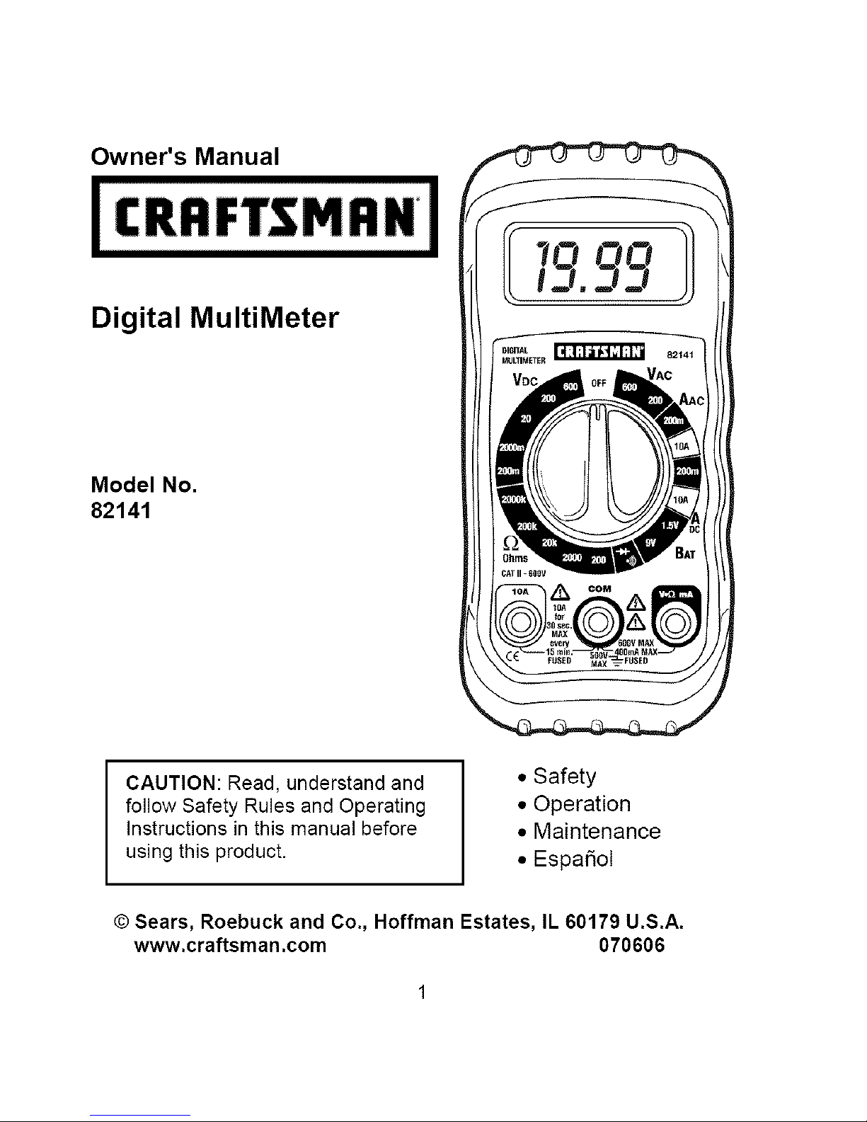
Owner's Manual
Digital MultiMeter
Model No.
82141
CAUTION: Read, understand and
follow Safety Rules and Operating
Instructions in this manual before
using this product.
• Safety
• Operation
• Maintenance
• Espafiol
© Sears, Roebuck and Co., Hoffman Estates, IL 60179 U.S.A.
www.craftsman.com 070606
r:_ :] i :[o] |o[o] _/ / _ _/ 1_
Warranty
Safety Instructions
Safety Symbols
Control and Jacks
Symbols and Annunciators
Specifications
Battery Installation
Operating Instructions
DC Voltage Measurements
AC Voltage Measurements
DC Current Measurements
AC Current Measurements
Resistance Measurements
Continuity Check
Diode Test
Battery Test
Maintenance
Replacing Batteries
Replacing Fuses
Troubleshooting
Service and Parts
Page
3
4
5
6
6
7
9
10
10
11
12
13
14
14
15
15
16
17
17
18
18
ONEYEARFULLWARRANTYONCRAFTSMANMANUALRANGING
MULTIMETER
IfthisCRAFTSMANManualRangingMultiMeterfailstogivecomplete
satisfactionwithinoneyearfromthedateofpurchase,RETURNITTO
THENEARESTSEARSSTOREOROTHERCRAFTSMANOUTLETIN
THEUNITEDSTATES,andSearswillreplaceit,freeofcharge.
IfthisCRAFTSMANManualRangingMultiMeterisusedforcommercial
orrentalpurposes,thiswarrantyappliesfor90daysfromthedateof
purchase.
Thiswarrantygivesyouspecificlegalrights,andyoumayalsohave
otherrightswhichvaryfromstatetostate
Sears,RoebuckandCo.,Dept.817WA,HoffmanEstates,IL60179
For Customer Assistance Call 9am-5 PM (EST)
Monday through Friday 1-888-326-1006
WARNING: USE EXTREME CAUTION IN THE USE OF THIS DEVICE.
Improper use of this device can result in injury or death. Follow all
safeguards suggested in this manual. In addition to the normal safety
precautions used in working with electrical circuits. DO NOT service this
device if you are not qualified to do so.
Thismeterhasbeendesignedforsafeuse,butmustbeoperatedwith
caution.Theruleslistedbelowmustbecarefullyfollowedforsafeoperation.
1. NEVERapplyvoltageorcurrenttothemeterthatexceedsthe
specifiedmaximum:
InputLimits
Function MaximumInput
VAC 600VDC/AC
VDCorVAC 600VDC/AC,200Vrmson200mVrange
mADC 200mA250Vfastactingfuse
ADC 10A250Vfastactingfuse(30secondsmax
every15 minutes)
Resistance, Continuity 250Vrms for 15sec max
2. USE EXTREME CAUTION when working with high voltages.
3. DO NOT measure voltage if the voltage on the "COM" input jack
exceeds 500V above earth ground.
4. NEVER connect the meter leads across a voltage source while the
function switch is in the current, resistance, or diode mode. Doing so
can damage the meter.
5. ALWAYS discharge filter capacitors in power supplies and disconnect
the power when making resistance or diode tests.
6. ALWAYS turn off the power and disconnect the test leads before
opening the doors to replace the fuse or batteries.
7. NEVER operate the meter unless the back cover and the battery and
fuse doors are in place and fastened securely.
3_'I_I=IIli'db_'d;4:[o]l
LWARN,NGI
IcAut'°NI
'sMAX
00V
i
m
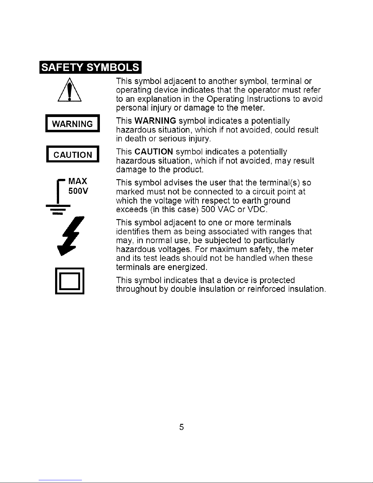
This symbol adjacent to another symbol, terminal or
operating device indicates that the operator must refer
to an explanation in the Operating Instructions to avoid
personal injury or damage to the meter.
This WARNING symbol indicates a potentially
hazardous situation, which if not avoided, could result
in death or serious injury.
This CAUTION symbol indicates a potentially
hazardous situation, which if not avoided, may result
damage to the product.
This symbol advises the user that the terminal(s) so
marked must not be connected to a circuit point at
which the voltage with respect to earth ground
exceeds (in this case) 500 VAC or VDC.
This symbol adjacent to one or more terminals
identifies them as being associated with ranges that
may, in normal use, be subjected to particularly
hazardous voltages. For maximum safety, the meter
and its test leads should not be handled when these
terminals are energized.
This symbol indicates that a device is protected
throughout by double insulation or reinforced insulation.
o_o]_IIII_,To]L',]F:I _Ie]LnlT:T_[(_
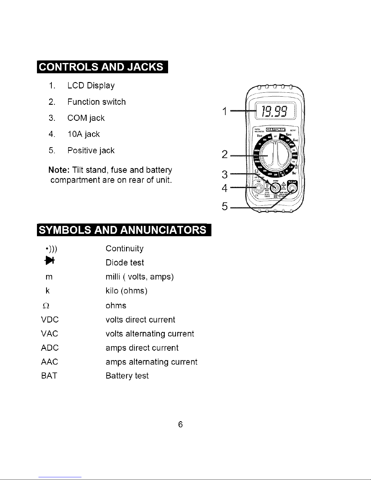
1. LCD Display
2. Function switch
3. COM jack
4. 10A jack
5. Positive jack
Note: Tilt stand, fuse and battery
compartment are on rear of unit.
H =O __k, | __k, k, k, __ O_
•))) Continuity
{1_ Diode test
m milli ( volts, amps)
k kilo (ohms)
£_ ohms
VDC volts direct current
VAC volts alternating current
ADC amps direct current
AAC amps alternating current
BAT Battery test
m
2_
3_
4_
5
Function
DC Voltage
(V DC)
AC Voltage
(V AC)
DC Current
(A DC)
AC Current
(A AC)
Resistance
Battery Test
Range
200mV
2000mV
20V
200V
600V
200V
600V
200mA
10A
200mA
10A
200£2
2000£!
20k£_
200k£_
2000k£_
9V
1.5V
Resolution
0.1mV
lmV
0.01V
0.1V
1V
0.1V
1V
100pA
10mA
100pA
10mA
0.1E_
1£2
0.01 k£_
0.1k£_
lk£_
lOmV
lOmV
Accuracy
+(0.5% reading + 2 digits)
+(1.5% reading + 5 digits
(50/60Hz)
+(1.2% reading + 2 digits)
+(2.0% reading + 2 digits)
+(1.8% reading + 5 digits)
+(3.0% reading + 5 digits)
+(0.8% reading + 2 digits)
+(1.0% reading + 2 digits)
+(1.0% reading + 2 digits)
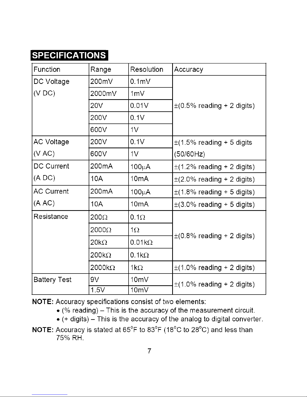
NOTE: Accuracy specifications consist of two elements:
• (% reading) - This is the accuracy of the measurement circuit.
• (+ digits) - This is the accuracy of the analog to digital converter.
NOTE: Accuracy is stated at 65°F to 83°F (18°C to 28°C) and less than
75% RH.
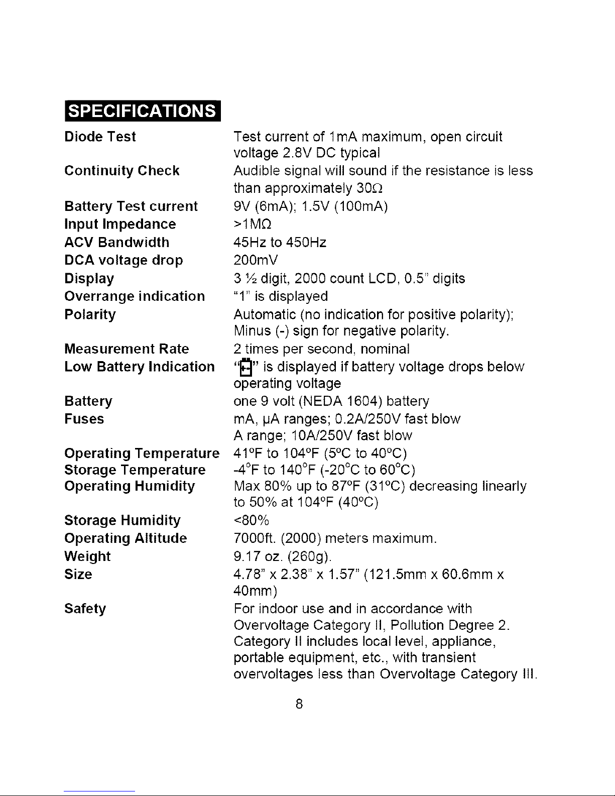
DiodeTest
ContinuityCheck
Battery Test current
Input Impedance
ACV Bandwidth
DCA voltage drop
Display
Overrange indication
Polarity
Measurement Rate
Low Battery Indication
Battery
Fuses
Operating Temperature
Storage Temperature
Operating Humidity
Storage Humidity
Operating Altitude
Weight
Size
Safety
Test current of 1mA maximum, open circuit
voltage 2.8V DC typical
Audible signal will sound if the resistance is less
than approximately 30£2
9V (6mA); 1.5V (100mA)
>1M£2
45Hz to 450Hz
200mV
3 ½ digit, 2000 count LCD, 0.5" digits
"1" is displayed
Automatic (no indication for positive polarity);
Minus (-) sign for negative polarity.
2 times per second, nominal
"_" is displayed if battery voltage drops below
operating voltage
one 9 volt (NEDA 1604) battery
mA, IJA ranges; 0.2A/250V fast blow
A range; 10A/250V fast blow
41°F to 104°F (5°C to 40°C)
-4°F to 140°F (-20°C to 60°C)
Max 80% up to 87°F (31°C) decreasing linearly
to 50% at 104°F (40°C)
<80%
7000ft. (2000) meters maximum.
9.17 oz. (260g).
4.78" x 2.38" x 1.57" (121.5mm x 60.6mm x
40mm)
For indoor use and in accordance with
Overvoltage Category II, Pollution Degree 2.
Category II includes local level, appliance,
portable equipment, etc., with transient
overvoltages less than Overvoltage Category III.

I WARNING: To avoid electric shock, disconnect the test leads from any I
source of voltage before removing the battery door. I
1.
2.
3.
4.
Disconnect the test leads from the meter.
Remove the protective rubber holster (if installed)_._t _
Open the battery door by loosening the screw using a
Phillips head screwdriver.
Insert the battery into battery holder, observing the
correct polarity.
Put the battery door back in place. Secure with the
screw.
I WARNING: To avoid electric shock, do not operate the meter until the I
battery door is in place and fastened securely.
I
NOTE: If your meter does not work properly, check the fuses and batteries
to make sure that they are still good and that they are properly inserted.
JWARNING: Risk of electrocution. High-voltage circuits, both AC and DC, J
are very dangerous and should be measured with great care.
I
1. ALWAYS turn the function switch to the OFF position when the meter is
not in use.
2. If "1" appears in the display during a measurement, the value exceeds
the range you have selected. Change to a higher range.
NOTE: On some low AC and DC voltage ranges, with the test leads not
connected to a device, the display may show a random, changing
reading. This is normal and is caused by the high-input sensitivity.
The reading will stabilize and give a proper measurement when
connected to a circuit.
DC VOLTAGE MEASUREMENTS
J AUTION: Do not measure DC voltages if a motor on the circuit is
being switched ON or OFF. Large voltage surges may occur that can
damage the meter.
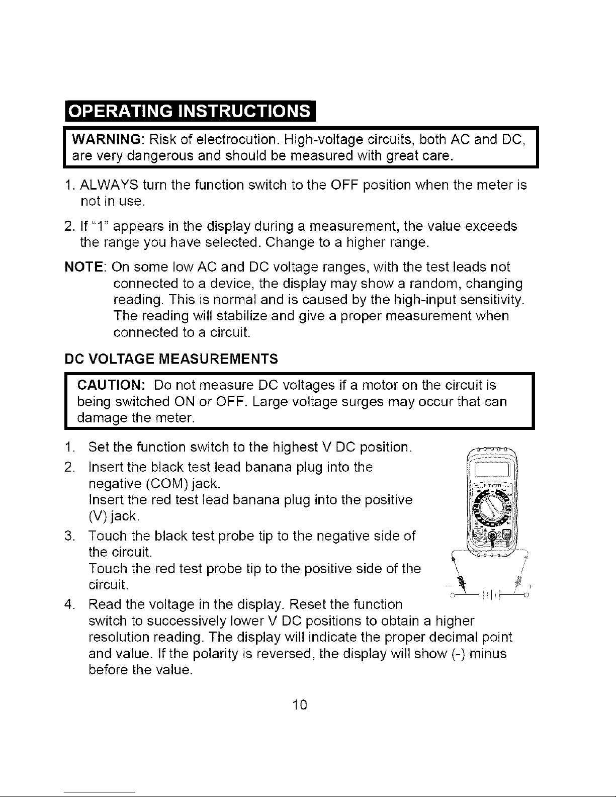
1. Set the function switch to the highest V DC position.
2. Insert the black test lead banana plug into the
negative (COM) jack.
Insert the red test lead banana plug into the positive
(V) jack.
3. Touch the black test probe tip to the negative side of
the circuit.
Touch the red test probe tip to the positive side of the
circuit.
4. Read the voltage in the display. Reset the function
switch to successively lower V DC positions to obtain a higher
resolution reading. The display will indicate the proper decimal point
and value. If the polarity is reversed, the display will show (-) minus
before the value.
I
10
AC VOLTAGE MEASUREMENTS
WARNING: Risk of Electrocution. The probe tips may not be long
enough to contact the live parts inside some 240V outlets for
appliances because the contacts are recessed deep in the outlets. As
a result, the reading may show 0 volts when the outlet actually has
voltage on it. Make sure the probe tips are touching the metal contacts
inside the outlet before assuming that no voltage is present.
I CAUTION: Do not measure AC voltages if a motor on the circuit is
being switched ON or OFF. Large voltage surges may occur that can
Idamage the meter.
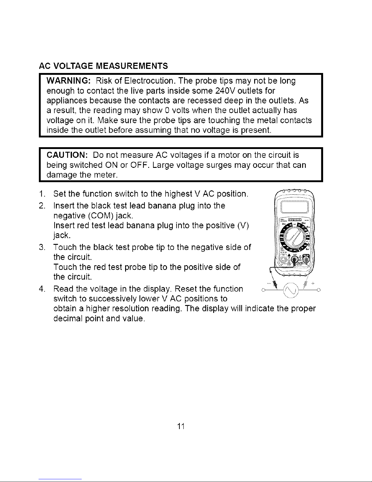
1. Set the function switch to the highest V AC position.
2. Insert the black test lead banana plug into the
negative (COM) jack.
Insert red test lead banana plug into the positive (V)
jack.
3. Touch the black test probe tip to the negative side of
the circuit.
Touch the red test probe tip to the positive side of
the circuit.
4. Read the voltage in the display. Reset the function
switch to successively lower V AC positions to
obtain a higher resolution reading. The display will indicate the proper
decimal point and value.
11
 Loading...