

Craftsman 82139 Owner's Manual
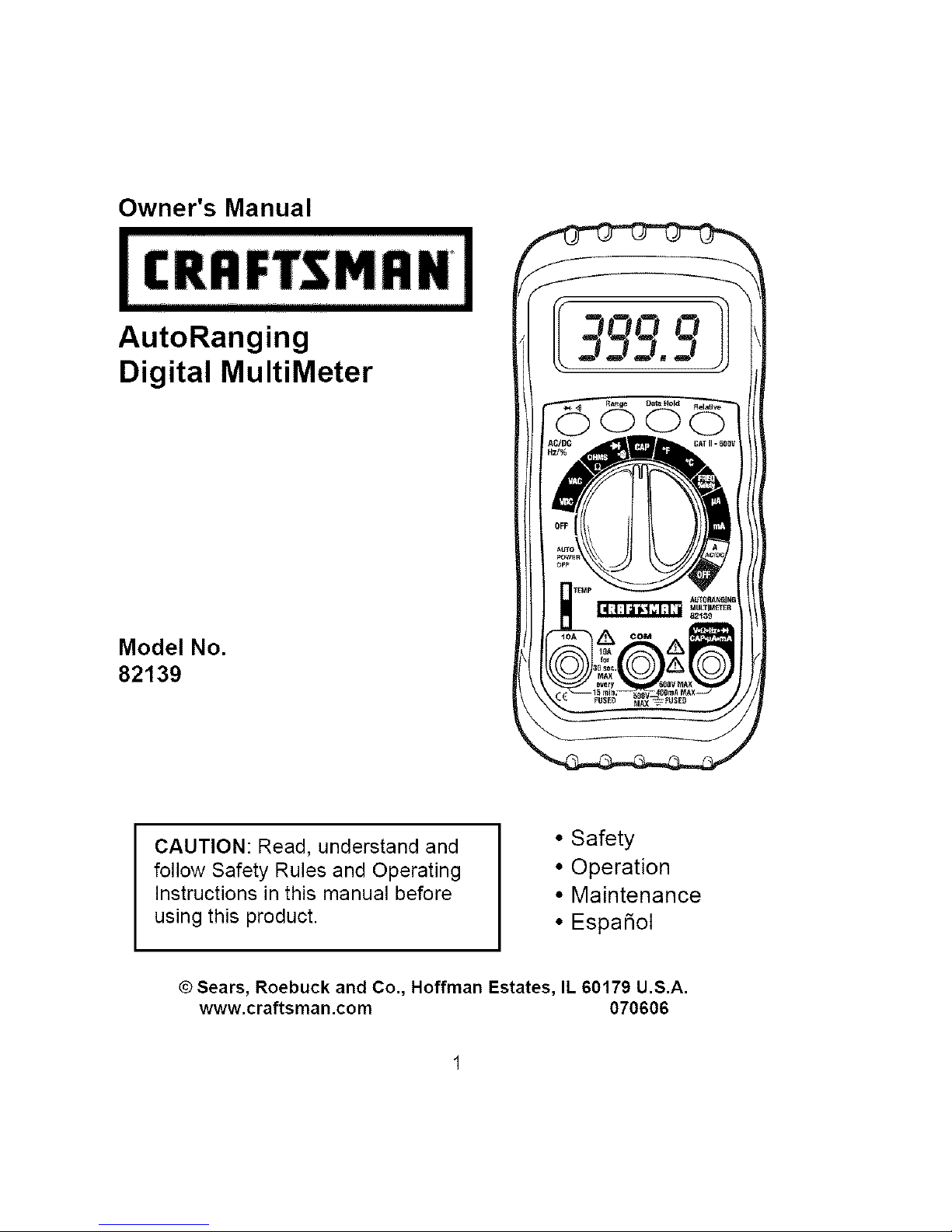
Owner's Manual
AutoRanging
Digital MultiMeter
Model No.
82139
I QQ O 1!
G
CAUTION: Read, understand and
follow Safety Rules and Operating
Instructions in this manual before
using this product.
• Safety
• Operation
• Maintenance
• EspaSoI
© Sears, Roebuck and Co., Hoffman Estates, IL 60179 U.S.A.
www.craftsman.com 070606
IP':_:] II :[o] _l[o[o]_i / :1_iII
Page
Warranty 3
Safety Instructions 3
Safety Symbols 4
Control and Jacks 5
Symbols and Annunciators 5
Specifications 6
Battery Installation 9
Operating Instructions 10
AutoRanging/ManualRanging 10
Data Hold 10
Relative 11
DC Voltage Measurements 11
AC Voltage Measurements 12
DC Current Measurements 12
AC Current Measurements 13
Resistance Measurements 14
Continuity Check 14
Diode Test 15
Frequency and Duty Cycle Measurements 15
Capacitance Measurements 16
Temperature Measurements 16
Maintenance 17
Replacing Batteries 17
Replacing Fuses 18
Troubleshooting 19
Service and Parts 19
D]_I:lk'd:1:1:1 ill I IlVlVl:l:] :;:1 _iI
ONE YEAR FULL WARRANTY ON CRAFTSMAN MULTIMETER
If this CRAFTSMAN Multimeter fails to give complete satisfaction within one year
from the date of purchase, RETURN IT TO THE NEAREST SEARS STORE OR
OTHER CRAFTSMAN OUTLET IN THE UNITED STATES, and Sears will replace
it, free of charge.
This warranty gives you specific legal rights, and you may also have other rights
which vary from state to state.
Sears, Roebuck and Co., Dept. 817WA, Hoffman Estates, IL 60179
For Customer Assistance Call 9am-5 PM (EST)
Monday through Friday 1-888-326-1006
I WARNING: USE EXTREME CAUTION IN THE USE OF THIS DEVICE.
Improper use of this device can result in injury or death. Follow all
safeguards suggested in this manual. In addition to the normal safety
precautions used in working with electrical circuits. DO NOT service this
device if you are not qualified to do so.
,_:1_ :ii'| I_[.'t /:|l[it t[e] _[.1
This meter has been designed for safe use, but must be operated with
caution. The rules listed below must be carefully followed for safe operation.
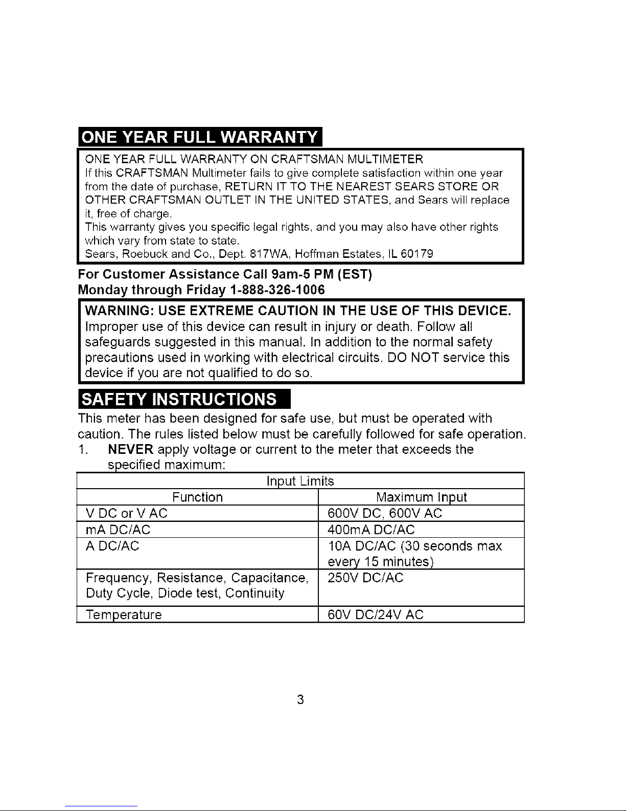
1. NEVER apply voltage or current to the meter that exceeds the
specified maximum:
Function
V DC or V AC
mA DC/AC
A DC/AC
Frequency, Resistance, Capacitance,
Duty Cycle, Diode test, Continuity
Temperature
Input Limits
Maximum Input
600V DC, 600V AC
400mA DC/AC
10A DC/AC (30 seconds max
every 15 minutes)
250V DC/AC
60V DC/24V AC
2. USEEXTREMECAUTIONwhen working with high voltages.
3. DO NOT measure voltage if the voltage on the "COM" input jack
exceeds 500V above earth ground.
4. NEVER connect the meter leads across a voltage source while the
function switch is in the current, resistance, or diode mode. Doing so
can damage the meter.
5. ALWAYS discharge filter capacitors in power supplies and disconnect
the power when making resistance or diode tests.
6. ALWAYS turn off the power and disconnect the test leads before
opening the doors to replace the fuse or batteries.
7. NEVER operate the meter unless the back cover and the battery and
fuse doors are in place and fastened securely.
ff.*1_1:11Ik'dl,.'b'd_v+I:[o] IB
±
LWARN,NGJ
IcAuT,°Ni
F MAX
500V
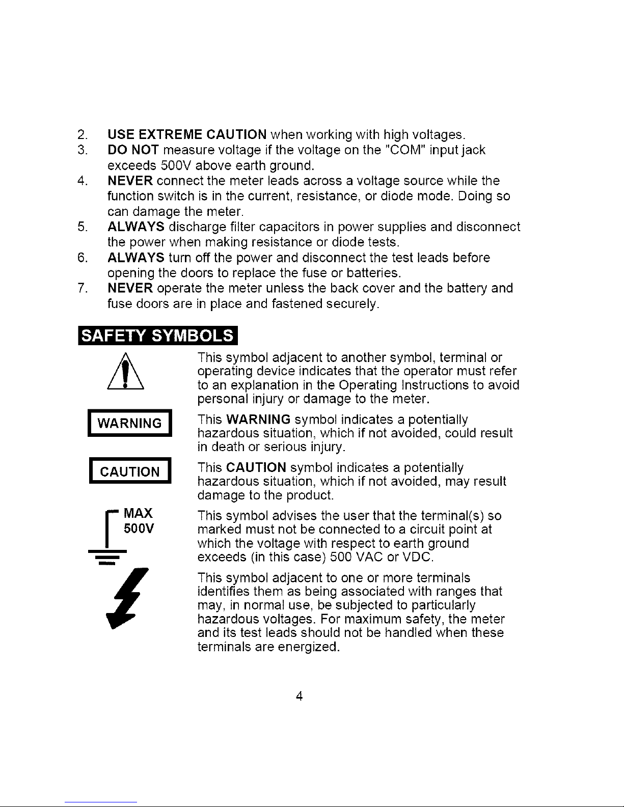
This symbol adjacent to another symbol, terminal or
operating device indicates that the operator must refer
to an explanation in the Operating Instructions to avoid
personal injury or damage to the meter.
This WARNING symbol indicates a potentially
hazardous situation, which if not avoided, could result
in death or serious injury.
This CAUTION symbol indicates a potentially
hazardous situation, which if not avoided, may result
damage to the product.
This symbol advises the user that the terminal(s) so
marked must not be connected to a circuit point at
which the voltage with respect to earth ground
exceeds (in this case) 500 VAC or VDC.
This symbol adjacent to one or more terminals
identifies them as being associated with ranges that
may, in normal use, be subjected to particularly
hazardous voltages. For maximum safety, the meter
and its test leads should not be handled when these
terminals are energized.

_To]_i / _To]iF.']r_*l_Ie]PF_*To_[(_
1. 4000 count Liquid Crystal Display
with symbolic signs
2. Function switch
3. Positive input jack
4. COM (negative) input jack
5. 10A (positive) input jack for 10A
DC or AC measurements
6. Continuity/Diode, Frequency/Duty
Cycle or AC/DC selection button.
7. Range pushbutton
8. Data Hold pushbutton
9. Relative pushbutton
10. Temperature socket
7
6
./,8
_9
_2
3
4
H-" • i_. II i_. _. _. i • _
o))) Continuity
BAT Low Battery
-IN Diode
DATA HOLD Data Hold
AUTO AutoRanging
AC Alternating Current or Voltage
DC Direct Current or Voltage
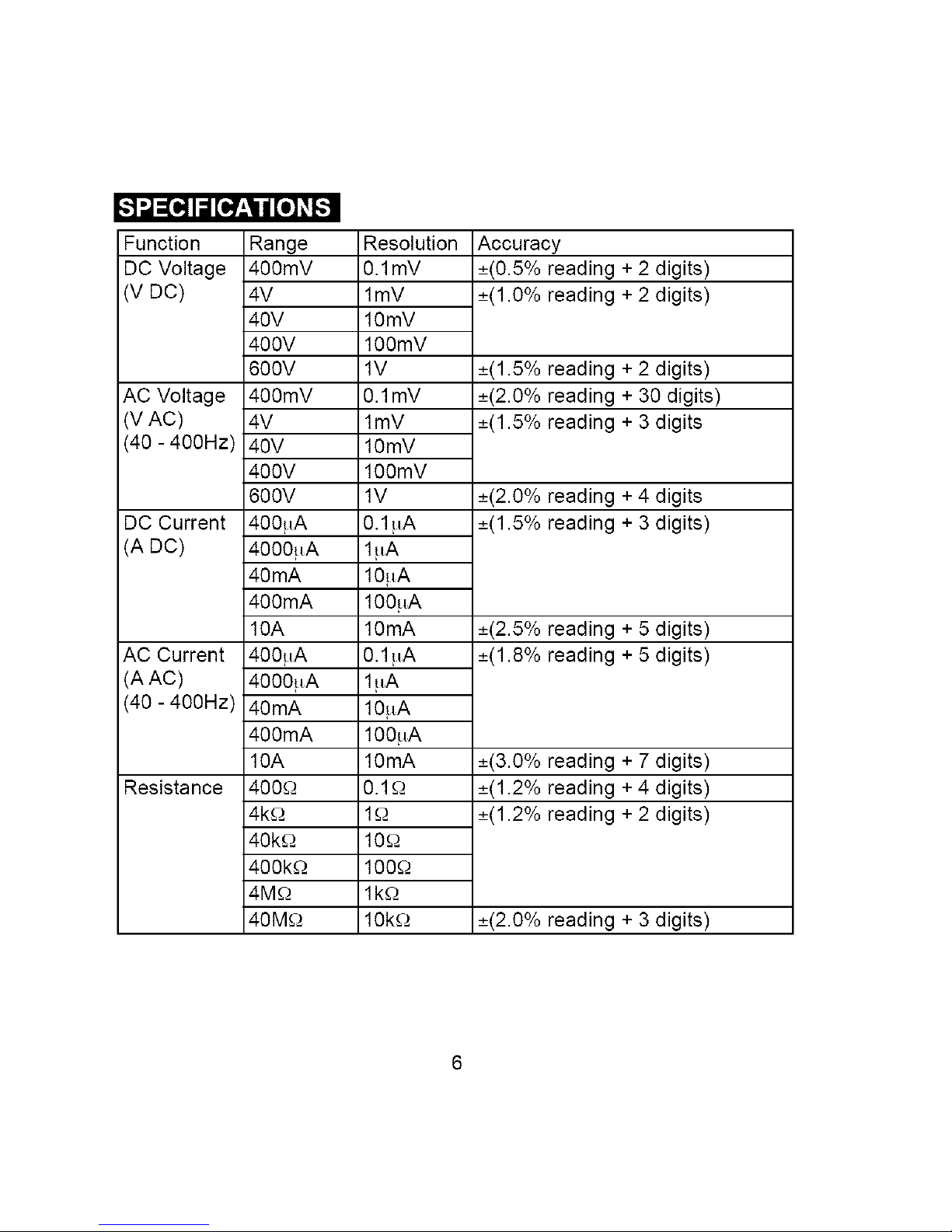
,t".,1_[l! IiI [___1t [.] _B
Function
DC Voltage
(V DC)
AC Voltage
(V AC)
(40 - 400Hz)
DC Current
(A DC)
AC Current
(A AC)
(40 - 400Hz)
Resistance
Range
400mY
4V
40V
400V
600V
400mY
4V
40V
400V
600V
400HA
4000HA
40mA
400mA
10A
400HA
4000HA
40mA
400mA
10A
400O-
4k£-.)
40k£-._
400k£-._
4M_.)
40M_.)
Resolution
0.1mV
lmV
10mV
100mV
1V
0.1mV
lmV
10mV
100mV
1V
0.1 HA
1HA
10HA
100HA
10mA
0.1 HA
1HA
10HA
100HA
10mA
0.1£-._
1£-._
10£-._
100£-._
lk£-._
10k£-._
Accuracy
_+(0.5%reading + 2 digits)
_+(1.0%reading + 2 digits)
_+(1.5%reading + 2 digits)
_+(2.0%reading + 30 digits)
_+(1.5%reading + 3 digits
_+(2.0%reading + 4 digits
_+(1.5%reading + 3 digits)
_+(2.5%reading + 5 digits)
_+(1.8%reading + 5 digits)
_+(3.0%reading + 7 digits)
_+(1.2%reading + 4 digits)
_+(1.2%reading + 2 digits)
_+(2.0%reading + 3 digits)
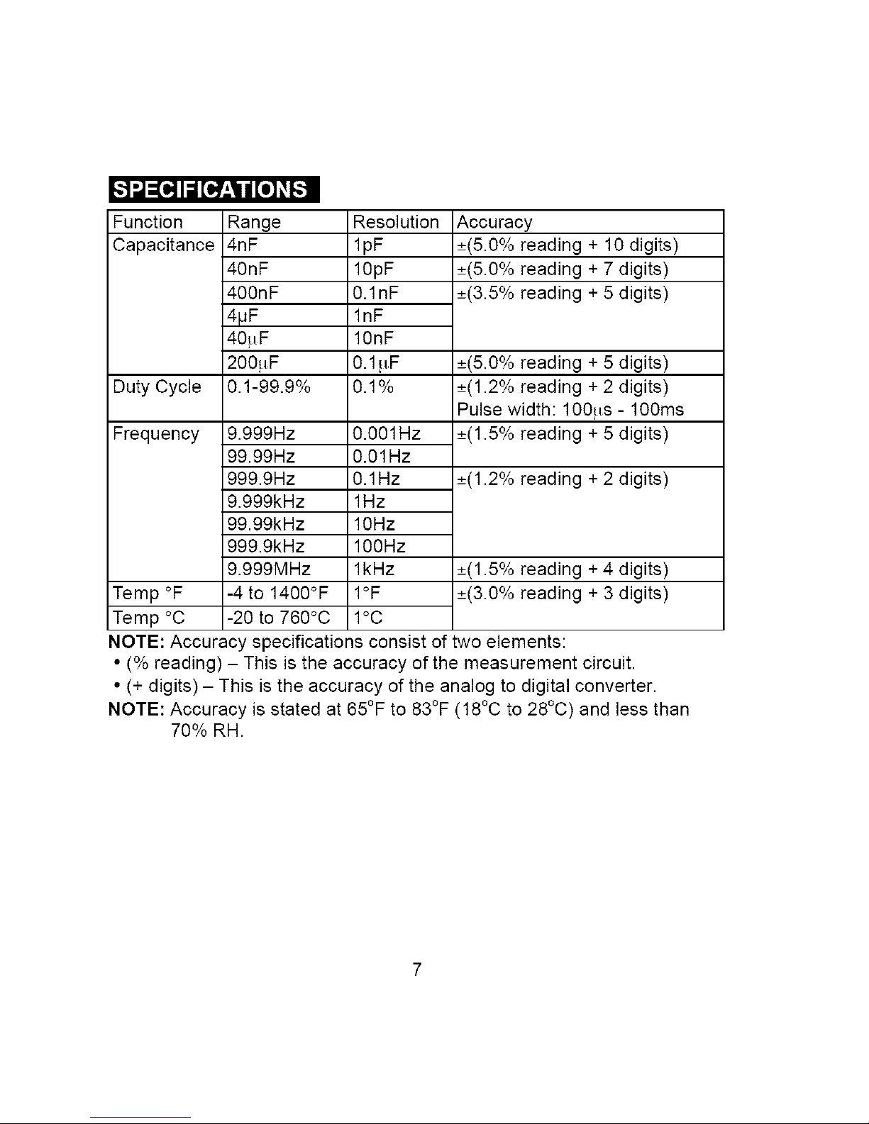
Function Range
Capacitance4nF
40nF
400nF
4IJF
40,uF
200,uF
DutyCycle0.1-99.9%
Frequency9.999Hz
99.99Hz
999.9Hz
9.999kHz
99.99kHz
999.9kHz
9.999MHz
Temp°F -4to1400°F
Temp°C -20to760°C
Resolution
lpF
10pF
0.1nF
lnF
10nF
0.1!iF
0.1%
0.001Hz
0.01Hz
0.1Hz
1Hz
10Hz
100Hz
lkHz
1OF
1oc
Accuracy
_+(5.0%reading+10digits)
_+(5.0%reading+7digits)
_+(3.5%reading+5digits)
_+(5.0%reading+5digits)
_+(1.2%reading+2digits)
Pulsewidth:100!_s-100ms
_+(1.5%reading+5digits)
_+(1.2%reading+2digits)
_+(1.5%reading+4digits)
_+(3.0%reading+3digits)
NOTE:Accuracyspecificationsconsistoftwoelements:
•(%reading)- Thisistheaccuracyofthemeasurementcircuit.
•(+digits)- Thisistheaccuracyoftheanalogtodigitalconverter.
NOTE:Accuracyisstatedat65°Fto83°F(18°Cto28°C)andlessthan
70%RH.
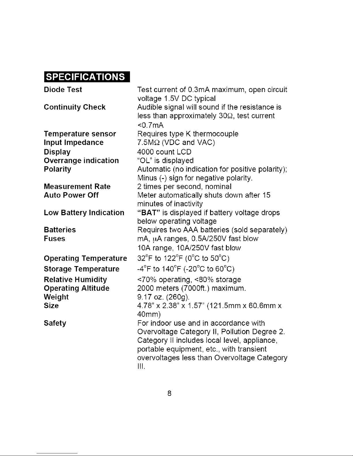
Diode Test
Continuity Check
Temperature sensor
Input Impedance
Display
Overrange indication
Polarity
Measurement Rate
Auto Power Off
Low Battery Indication
Batteries
Fuses
Operating Temperature
Storage Temperature
Relative Humidity
Operating Altitude
Weight
Size
Safety
Test current of 0.3mA maximum, open circuit
voltage 1.5V DC typical
Audible signal will sound if the resistance is
less than approximately 30£-._,test current
<0.7mA
Requires type K thermocouple
7.5M£-2(VDC and VAC)
4000 count LCD
"OL" is displayed
Automatic (no indication for positive polarity);
Minus (-) sign for negative polarity.
2 times per second, nominal
Meter automatically shuts down after 15
minutes of inactivity
"BAT" is displayed if battery voltage drops
below operating voltage
Requires two AAA batteries (sold separately)
mA, !_A ranges, 0.5A/250V fast blow
10A range, 10A/250V fast blow
32°F to 122°F (0°C to 50°C)
-4°F to 140°F (-20°C to 60°C)
<70% operating, <80% storage
2000 meters (7000ft.) maximum.
9.17 oz. (260g).
4.78" x 2.38" x 1.57" (121.5mm x 60.6mm x
40mm)
For indoor use and in accordance with
Overvoltage Category II, Pollution Degree 2.
Category II includes local level, appliance,
portable equipment, etc., with transient
overvoltages less than Overvoltage Category
III.
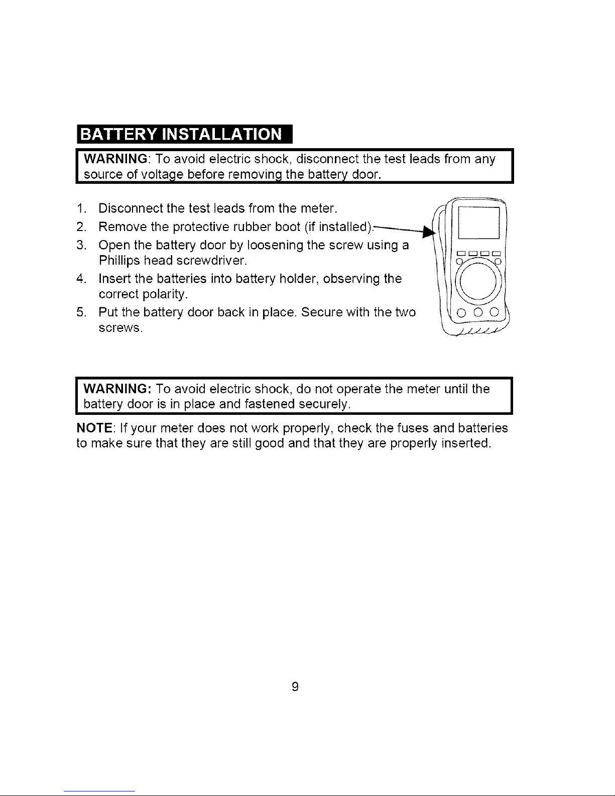
IWARNING:Toavoidelectricshock,disconnectthetestleadsfromany
sourceofvoltagebeforeremovingthebatterydoor.
1. Disconnectthetestleadsfromthemeter.
2. Removetheprotectiverubberboot(ifinstalled).---_-_
3. Openthebatterydoorbylooseningthescrewusinga
Phillipsheadscrewdriver.
4. Insertthebatteriesintobatteryholder,observingthe
correctpolarity.
5. Putthebatterydoorbackinplace.Securewiththetwo
screws.
I WARNING: To avoid electric shock, do not operate the meter until the I
battery door is in place and fastened securely.
I
NOTE: If your meter does not work properly, check the fuses and batteries
to make sure that they are still good and that they are properly inserted.
I ARNING: Risk of electrocution. High-voltage circuits, both AC and DC,
are very dangerous and should be measured with great care.
1. ALWAYS turn the function switch to the OFF position when the meter is
not in use. This meter has Auto OFF that automatically shuts the meter
OFF if 15 minutes elapse between uses.
2. If "OL" appears in the display during a measurement, the value exceeds
the range you have selected. Change to a higher range.
NOTE: On some low AC and DC voltage ranges, with the test leads not
connected to a device, the display may show a random, changing
reading. This is normal and is caused by the high-input sensitivity.
The reading will stabilize and give a proper measurement when
connected to a circuit.
AUTORANGING / MANUALRANGING SELECTION
When the meter is first turned on, it automatically goes into AutoRanging.
This automatically selects the best range for the measurements being
made and is generally the best mode for most measurements. For
measurement situations requiring that a range be manually selected,
perform the following:
1. Press the RANGE button. The "AUTO" display indicator will turn off.
2. Press the RANGE button to step through the available ranges until you
select the range you want.
3. Press and hold the RANGE button for 2 seconds to exit the
ManualRanging mode and return to AutoRanging.
DATA HOLD
The Data Hold function allows the meter to "freeze" a measurement for
later reference.
1. Press the DATA HOLD button to "freeze" the reading on the indicator.
The indicator "HOLD" will appear in the display.
2. Press the DATA HOLD button to return to normal operation.
NOTE: The DATA HOLD function works in the FREQUENCY mode only
when a signal is present.
10
RELATIVE
The relative measurement feature allows you to make measurements
relative to a stored reference value. A reference voltage, current, etc. can
be stored and measurements made in comparison to that value. The
displayed value is the difference between the reference value and the
measured value.
1. Perform any measurement as described in the operating instructions.
2. Press the RELATIVE button to store the reading in the display and the
"REL" indicator will appear on the display.
3. The display will now indicate the difference between the stored value
and the measured value.
4. Press the RELATIVE button to return to normal operation.
DC VOLTAGE MEASUREMENTS
I AUTION: Do not measure DC voltages if a motor on the circuit is I
being switched ON or OFF. Large voltage surges may occur that can
I
damage the meter.
1. Set the function switch to the V DC position CmV" will
appear in the display).
2. Insert the black test lead banana plug into the negative
(COM) jack and the red test lead banana plug into the
positive (V) jack.
3. Touch the test probe tips to the circuit under test. Be
sure to observe the correct polarity (red lead to
positive, black lead to negative).
4. Read the voltage in the display. The display will
indicate the proper decimal point and value. If the
polarity is reversed, the display will show (-) minus before the value.
11
AC VOLTAGE MEASUREMENTS
WARNING: Risk of Electrocution. The probe tips may not be long
enough to contact the live parts inside some 240V outlets for
appliances because the contacts are recessed deep in the outlets. As
a result, the reading may show 0 volts when the outlet actually has
voltage on it. Make sure the probe tips are touching the metal contacts
inside the outlet before assuming that no voltage is present.
CAUTION: Do not measure AC voltages if a motor on the circuit is
being switched ON or OFF. Large voltage surges may occur that can
damage the meter.
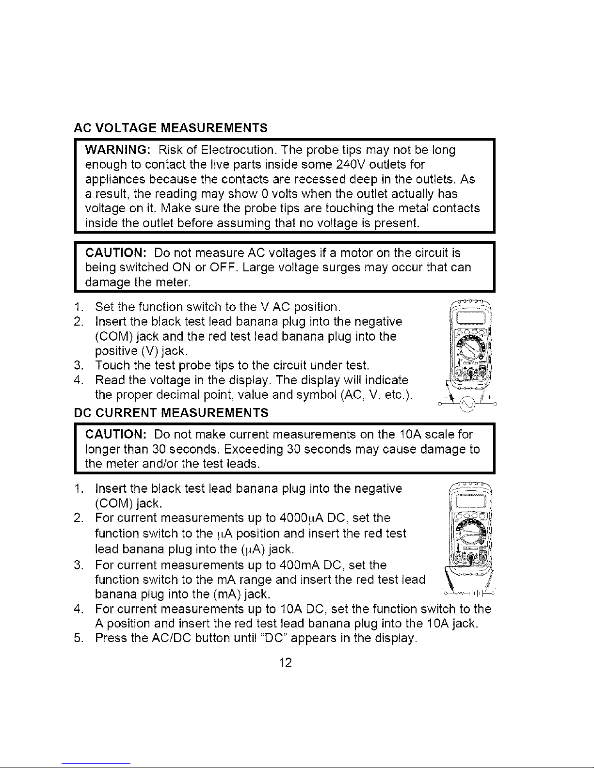
1. Set the function switch to the V AC position.
2. Insert the black test lead banana plug into the negative
(COM) jack and the red test lead banana plug into the
positive (V) jack.
3. Touch the test probe tips to the circuit under test.
4. Read the voltage in the display. The display will indicate
the proper decimal point, value and symbol (AC, V, etc.).
DC CURRENT MEASUREMENTS
I CAUTION: DO not make current measurements on the 10A scale for I
I
longer than 30 seconds. Exceeding 30 seconds may cause damage to
the meter and/or the test leads.
1. Insert the black test lead banana plug into the negative
(COM) jack.
2. For current measurements up to 4000!_A DC, set the
function switch to the !_A position and insert the red test
lead banana plug into the (!_A)jack.
3. For current measurements up to 400mA DC, set the
function switch to the mA range and insert the red test lead
banana plug into the (mA) jack.
4. For current measurements up to 10A DC, set the function switch to the
A position and insert the red test lead banana plug into the 10A jack.
5. Press the AC/DC button until "DC" appears in the display.
12
 Loading...