

Craftsman 82024 Owner's Manual
Owner's Manual
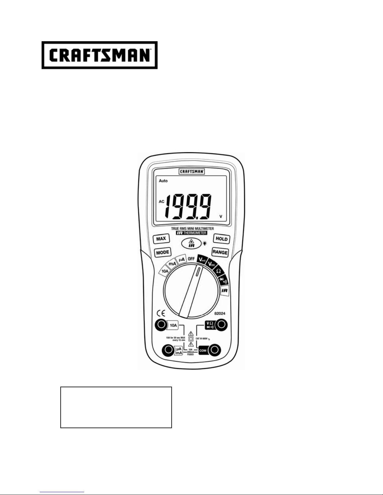
True RMS Multimeter with IR Thermometer
Model No. 82024
Sears Brands Management Corporation, Hoffman Estates, IL 60179 U.S.A.
www.craftsman.com 122112
CAUTION: Read, understand and
follow Safety Rules and Operating
Instructions in this manual before
using this product.
Safety
Operation
Maintenance
Español
2
TABLE OF CONTENTS
Warranty Page 2
Safety Instructions 3
Safety Symbols 4
Control and Jacks 5
Symbols and Annunciators 5
Specifications 6
Battery anf Fuse Replacement 8
Operating Instructions 9
AC/DC Voltage Measurements 10
AC/DC Current Measurements 10
Resistance Measurements 10
Continuity Check 11
Diode Test 11
IR Temperature Measurements 12
Maintenance 13
Troubleshooting 13
Service and Parts 13
ONE YEAR FULL WARRANTY
CRAFTSMAN ONE YEAR FULL WARRANTY
FOR ONE YEAR from the date of purchase, this product is warranted against defects in material or
workmanship. A defective product will be replaced free of charge.
For warranty coverage details to obtain free replacement, visit the web site: www.craftsman.com
This warranty is void if this product is ever used while providing commercial services or if rented to
another person.
This warranty gives you specific legal rights, and you may also have other rights which vary from
state to state.
Sears Brands Management Corporation, Hoffman Estates, IL 60179
For Customer Assistance Call 9am - 5pm (ET)
Monday through Friday 1-888-326-1006
WARNING: USE EXTREME CAUTION IN THE USE OF THIS DEVICE. Improper use of this device
can result in injury or death. Follow all safeguards suggested in this manual in addition to the normal
safety precautions used in working with electrical circuits. DO NOT service this device if you are not
qualified to do so.
3
SAFETY INSTRUCTIONS
This meter has been designed for safe use, but must be operated with caution. The rules listed below
must be carefully followed for safe operation.
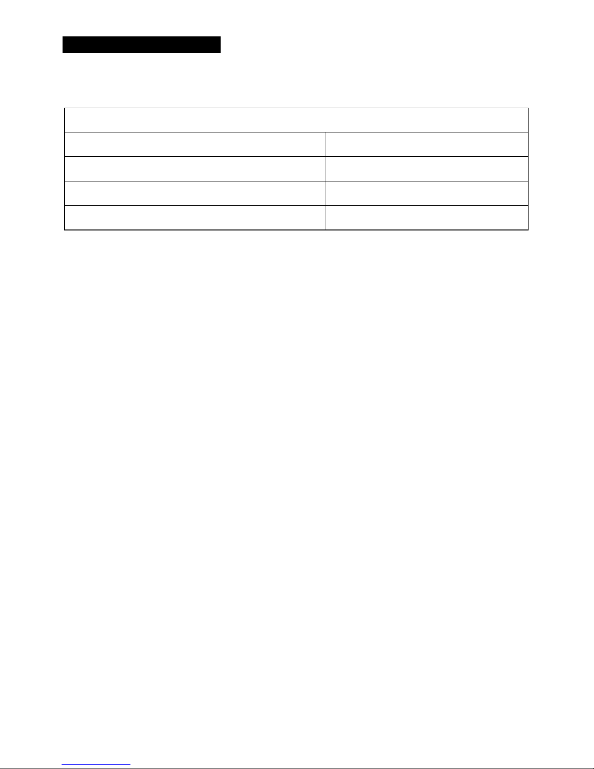
1. NEVER apply voltage or current to the meter that exceeds the specified maximum:
Input Protection Limits
Function Maximum Input
V AC/DC, Resistance, Diode Test, Continuity 600 VDC/AC rms
μA or mA AC/DC 200mA fused
A AC/DC 10A fused
2. USE EXTREME CAUTION when working with high voltages.
3. DO NOT measure voltage if the voltage on the "COM" input jack exceeds 600V above earth
ground.
4. NEVER connect the meter leads across a voltage source while the function switch is in the
current, resistance, or diode mode. Doing so can damage the meter.
5. ALWAYS discharge filter capacitors in power supplies and disconnect the power when making
resistance or diode tests.
6. ALWAYS turn off the power and disconnect the test leads before opening the covers to replace
the fuse or batteries.
7. NEVER operate the meter unless the back cover and the battery and fuse covers are in place
and fastened securely.
8. If the equipment is used in a manner not specified by the manufacturer, the protection provided
by the equipment may be impaired.
4
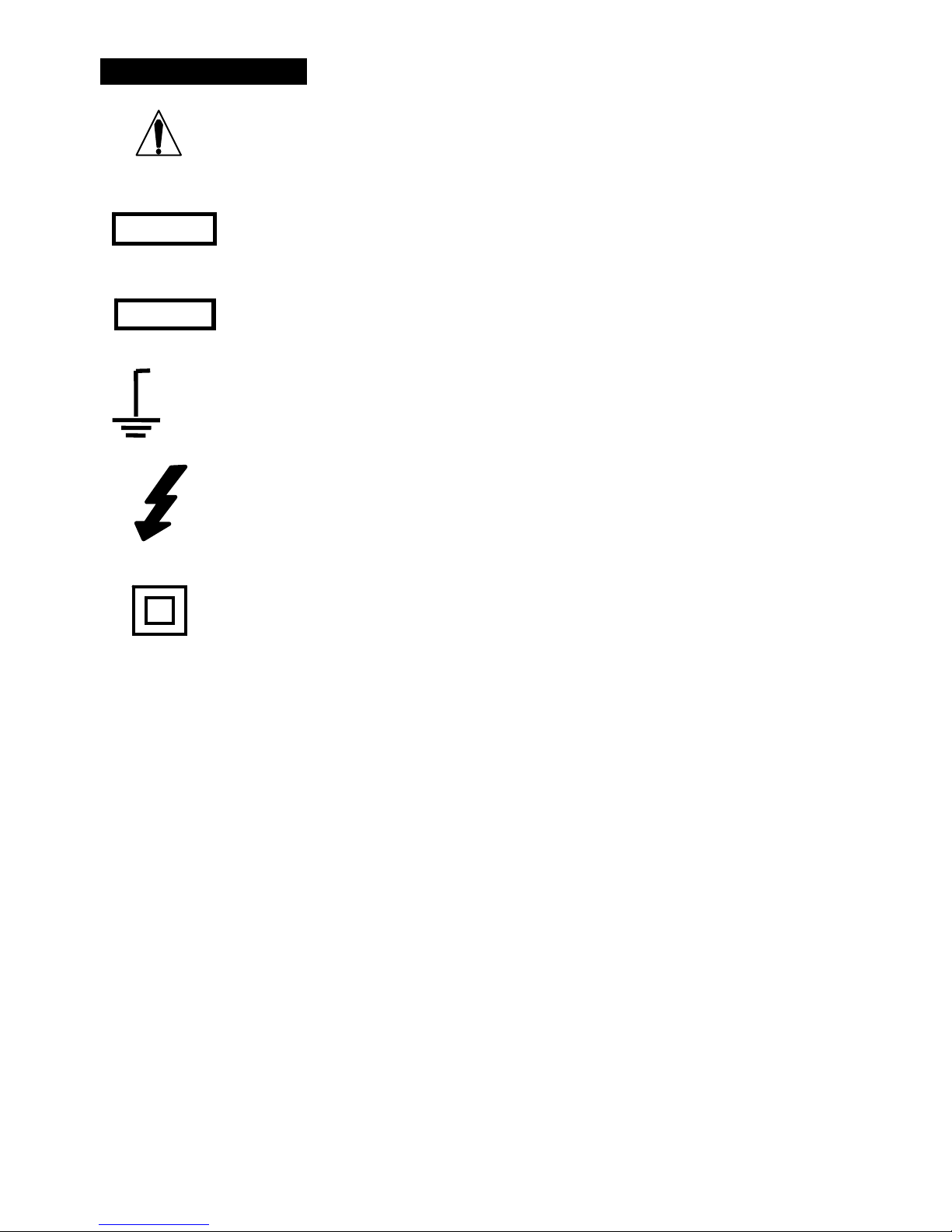
SAFETY SYMBOLS
This symbol adjacent to another symbol, terminal or operating device indicates
that the operator must refer to an explanation in the Operating Instructions to
avoid personal injury or damage to the meter.
This WARNING symbol indicates a potentially hazardous situation, which if not
avoided, could result in death or serious injury.
This CAUTION symbol indicates a potentially hazardous situation, which if not
avoided, may result damage to the product.
This symbol advises the user that the terminal(s) so marked must not be
connected to a circuit point at which the voltage with respect to earth ground
exceeds (in this case) 600 VAC or VDC.
This symbol adjacent to one or more terminals identifies them as being associated
with ranges that may, in normal use, be subjected to particularly hazardous
voltages. For maximum safety, the meter and its test leads should not be handled
when these terminals are energized.
This symbol indicates that a device is protected throughout by double insulation or
reinforced insulation.
PER IEC1010 OVERVOLTAGE INSTALLATION CATEGORY
OVERVOLTAGE CATEGORY I
Equipment of OVERVOLTAGE CATEGORY I is equipment for connection to circuits in which
measures are taken to limit the transient overvoltages to an appropriate low level.
Note – Examples include protected electronic circuits.
OVERVOLTAGE CATEGORY II
Equipment of OVERVOLTAGE CATEGORY II is energy-consuming equipment to be supplied from
the fixed installation.
Note – Examples include household, office, and laboratory appliances.
OVERVOLTAGE CATEGORY III
Equipment of OVERVOLTAGE CATEGORY III is equipment in fixed installations.
Note – Examples include switches in the fixed installation and some equipment for industrial use
with permanent connection to the fixed installation.
OVERVOLTAGE CATEGORY IV
Equipment of OVERVOLTAGE CATEGORY IV is for use at the origin of the installation.
Note – Examples include electricity meters and primary over-current protection equipment
WARNING
CAUTION
MAX
600V
 Loading...