

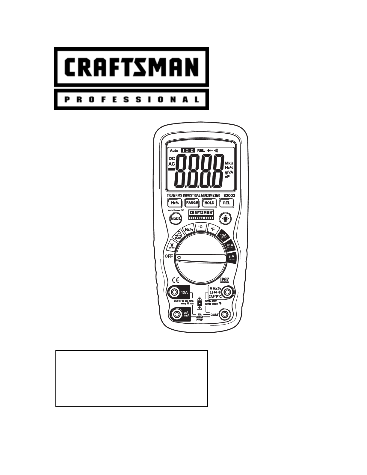
Craftsman 82003 Owner's Manual
Owner's Manual
True RMS
Multimeter
Model No.
82003
CAUTION: Read, understand and
follow Safety Rules and Operating
Instructions in this manual before
using this product.
Safety
Operation
Maintenance
Español
© Sears, Roebuck and Co., Hoffman Estates, IL 60179 U.S.A.
www.craftsman.com 042508

TABLE OF CONTENTS
Warranty Page 3
Safety Instructions 4
Safety Symbols 5
Control and Jacks 6
Symbols and Annunciators 6
Specifications 7
Battery Installation 11
Operating Instructions 12
DC Voltage Measurements 12
AC Voltage Measurements 13
DC Current Measurements 14
AC Current Measurements 15
Resistance Measurements 16
Continuity Check 17
Diode Test 17
Capacitance Measurements 18
Frequency (Duty Cycle) Measurements 18
Temperature Measurements 19
Autoranging/Manual range selection 20
Relative Mode 20
Display Backlight 21
Hold 21
Auto Power Off 21
Low Battery Indication 21
Maintenance 22
Battery Replacement 23
Fuse Replacement 24
Troubleshooting 25
Service and Parts 25
2

ONE YEAR FULL WARRANTY
CRAFTSMAN PROFESSIONAL ONE YEAR FULL
WARRANTY. If this product fails due to a defect in materials or
workmanship within one year from the date of purchase,
RETURN IT TO ANY SEARS STORE OR OTHER
CRAFTSMAN OUTLET IN THE UNITED STATES for free
replacement. This warranty gives you specific legal rights, and
you may also have other rights which vary from state to state.
Sears, Roebuck and Co., Hoffman Estates, IL 60179
For Customer Assistance Call 9am - 5pm (ET)
Monday through Friday 1-888-326-1006
WARNING: USE EXTREME CAUTION IN THE USE OF THIS
DEVICE. Improper use of this device can result in injury or
death. Follow all safeguards suggested in this manual in addition
to the normal safety precautions used in working with electrical
circuits. DO NOT service this device if you are not qualified to do
so.
3
SAFETY INSTRUCTIONS
This meter has been designed for safe use, but must be operated
with caution. The rules listed below must be carefully followed for
safe operation.
1. NEVER apply voltage or current to the meter that exceeds the
specified maximum:
Input Limits
Function Maximum Input
V DC or V AC 1000VDC/AC rms
mA AC/DC 400mA AC/DC
A AC/DC 10A AC/DC (20A for 30 seconds
max every 15 minutes)
Resistance, Diode Test,
1000VDC/AC rms
Continuity, Capacitance,
Frequency, Temperature
2. USE EXTREME CAUTION when working with high voltages
3. DO NOT measure voltage if the voltage on the "COM" input
jack exceeds 1000V above earth ground
4. DO NOT measure current of circuits whose voltage is greater
than 600V above earth ground
5. NEVER connect the meter leads across a voltage source
while the function switch is in the resistance or diode mode.
Doing so can damage the meter
6. ALWAYS turn off the power and disconnect the test leads
before opening the cover to replace the fuse or battery
7. NEVER operate the meter unless the back cover is in place
and fastened securely
4
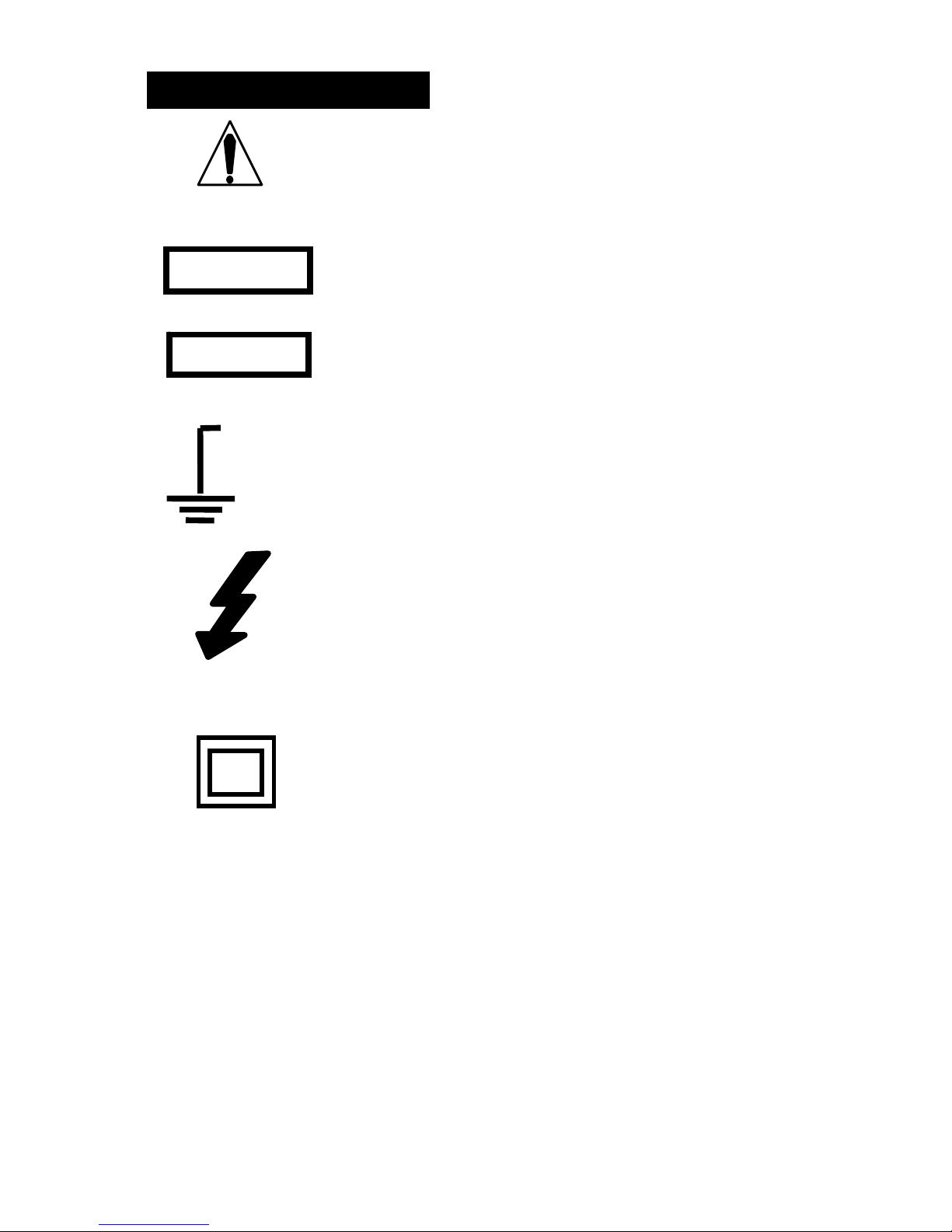
SAFETY SYMBOLS
This symbol adjacent to another symbol,
terminal or operating device indicates that the
operator must refer to an explanation in the
Operating Instructions to avoid personal injury
or damage to the meter.
WARNING
CAUTION
MAX
1000V
This WARNING symbol indicates a potentially
hazardous situation, which if not avoided,
could result in death or serious injury.
This CAUTION symbol indicates a potentially
hazardous situation, which if not avoided, may
result damage to the product.
This symbol advises the user that the
terminal(s) so marked must not be connected
to a circuit point at which the voltage with
respect to earth ground exceeds (in this case)
1000 VAC or VDC.
This symbol adjacent to one or more terminals
identifies them as being associated with
ranges that may, in normal use, be subjected
to particularly hazardous voltages. For
maximum safety, the meter and its test leads
should not be handled when these terminals
are energized.
This symbol indicates that a device is
protected throughout by double insulation or
reinforced insulation.
5
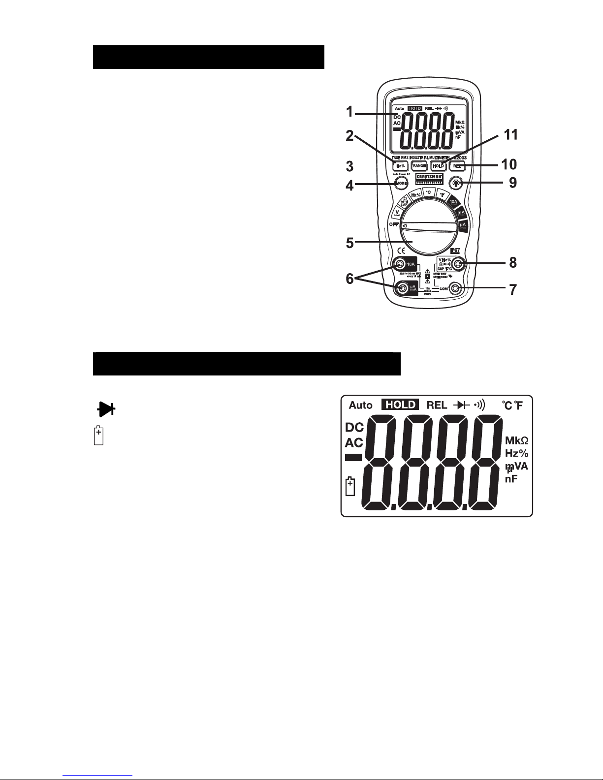
CONTROLS AND JACKS
1. 4,000 count LCD display
2. RANGE button
3. Hz and % button
4. Mode button
5. Function switch
6. mA, µA and 10A input jacks
7. COM input jack
8. Positive input jack
9. Backlight button
10. REL button
11. HOLD button
Note: Tilt stand and battery compartment are on rear of unit.
SYMBOLS AND ANNUNCIATORS
•))) Continuity
Diode test
Battery status
n nano (10
µ micro (10
m milli (10
A Amps
k kilo (10
F Farads (capacitance)
M mega (10
Ohms
Hz Hertz (frequency) V Volts
% Percent (duty ratio) REL Relative
AC Alternating current Auto Autoranging
-9
) (capacitance)
-6
) (amps)
-3
) (volts, amps)
3
) (ohms)
6
) (ohms)
DC Direct current HOLD Display hold
ºF Degrees Fahrenheit ºC Degrees Centigrade
6
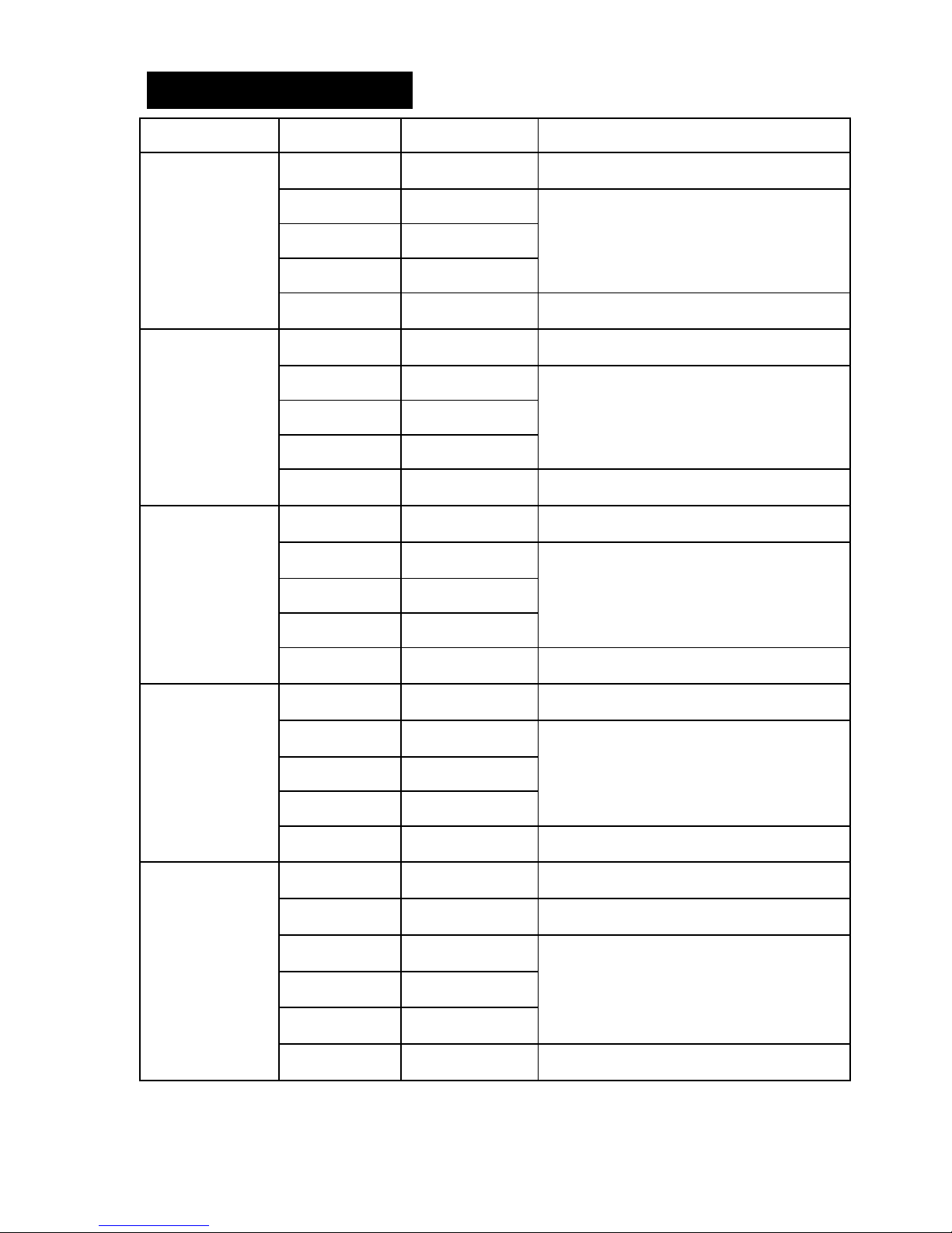
SPECIFICATIONS
Function Range Resolution Accuracy
DC Voltage
AC Voltage
DC Current
400mV 0.1mV
(0.5% reading + 2 digits)
4V 0.001V
40V 0.01V
(1.2% reading + 2 digits)
400V 0.1V
1000V 1V
400mV 0.1mV
(1.5% reading + 2 digits)
(2.0% reading + 10 digits)
4V 0.001V
40V 0.01V
(2.0% reading + 5 digits)
400V 0.1V
1000V 1V
(2.5% reading + 5 digits)
400A 0.1A (1.0% reading + 3 digits)
4000A 1A
40mA 0.01mA
(1.5% reading + 3 digits)
AC Current
Resistance
400mA 0.1mA
10A 0.01A
(2.5% reading + 5 digits)
400A 0.1A (2.5% reading + 10 digits)
4000A 1A
40mA 0.01mA
(2.5% reading + 5 digits)
400mA 0.1mA
10A 0.01A
(3.0% reading + 7 digits)
400 0.1 (1.2% reading + 4 digits)
4k 0.001k (1.0% reading + 2 digits)
40k 0.01k
400k 0.1k
(1.2% reading + 2 digits)
4M 0.001M
40M 0.01M (2.0% reading + 3 digits)
7
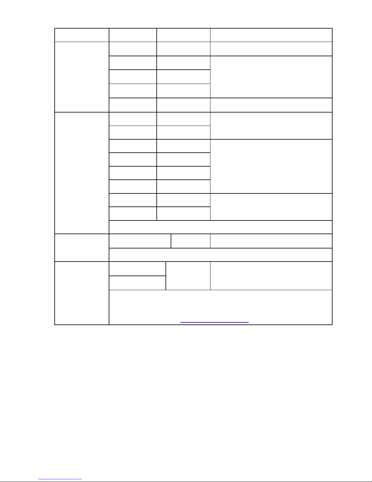
Function Range Resolution Accuracy
Capacitance
Frequency
40nF 0.01nF
(5.0% reading + 7 digits)
400nF 0.1nF
4F 0.001F
(3.0% reading + 5 digits)
40F 0.01F
100F 0.1F (5% reading + 5 digits)
5.999Hz 0.001Hz
(1.5% reading + 1 digits)
59.99Hz 0.01Hz
599.9Hz 0.1Hz
5.999kHz 0.001kHz
(1.2% reading + 3 digits)
59.99kHz 0.01kHz
599.9kHz 0.1kHz
5.999MHz 0.001MHz
(1.5% reading + 4 digits)
9.999MHz 0.001MHz
Sensitivity: 0.5V rms <500kHz; 3V rms >500kHz
Duty Cycle
0.1 to 99.9%
0.1%
(1.2% reading + 2 digits)
Pulse width: 100µs - 100ms, Frequency: 5Hz to 150kHz
Temp
(type-K)
-4 to 1382F
-20 to 750C
0.1<400
1 ≥ 400
(3.0% reading + 5C /9F )
(probe accuracy not included)
Supplied Probe range: -58.0 to 482
o
F (-50.0 to 250oC)
Note: An optional probe that is rated to the full range of the meter
is available from the www.craftsman.com
website.
Note: Accuracy is stated at 65oF to 83oF (18oC to 28oC) and less
than 75% RH.
Note: Accuracy specifications consist of two elements:
(% reading) – This is the accuracy of the measurement circuit.
(+ digits) – This is the accuracy of the analog to digital converter.
8
 Loading...