

Page 1

Operator's Manual
JCRAFTSMAN°I
BRUSHCU'I-rER A'I-rACHMENT
Model No.
358,792443
NOT DESIGNED FOR USE
WITH ELECTRIC POWERHEADS
• Safety
• Assembly
• Operation
• Maintenance
• Parts List
• Espar_ol, p. 17
DANGER:
Read and follow all Safety Rules and Operating
Instructions before first use of this product.
For answers to your questions about this product: Call 7
am-7 pm, Mon.-Sat., or 10 am-7 pm, Sun.
1-800-235-5878 (Hours listed are Central Time)
Sears, Roebuck and Co., Hoffman Estates, IL 60179 U.S.A.
530164972 9/12/06
Page 2
Warranty Statement 2 Service & Adjustments 14
Identification of Symbols 2 Storage 15
Safety Rules 2
Assembly 5
Parts List 16
Operation 10 Spanish 17
Maintenance 14 Parts and Ordering Back Cover
ONE YEAR FULL WARRANTY ON CRAFTSMAN ® BRUSHCUTTER ATTACHMENT
When used and maintained according to the operator's manual, ifthis product fails
due to a defect in material or workmanship within one year from the date of pur-
chase, return it to any Sears store, Sears Service Center, or other Craftsman outlet in
the United States for free repair (or replacement if repair proves impossible).
This warranty excludes expendable parts that can wear out from normal use in
less than one year.
This warranty applies for only 30 days from purchase date if this product is used
for commercial or rental purposes.
This warranty gives you specific legal rights, and you may also have other rights
which vary from state to state.
Sears, Roebuck and Co., Hoffman Estates, IL 60179
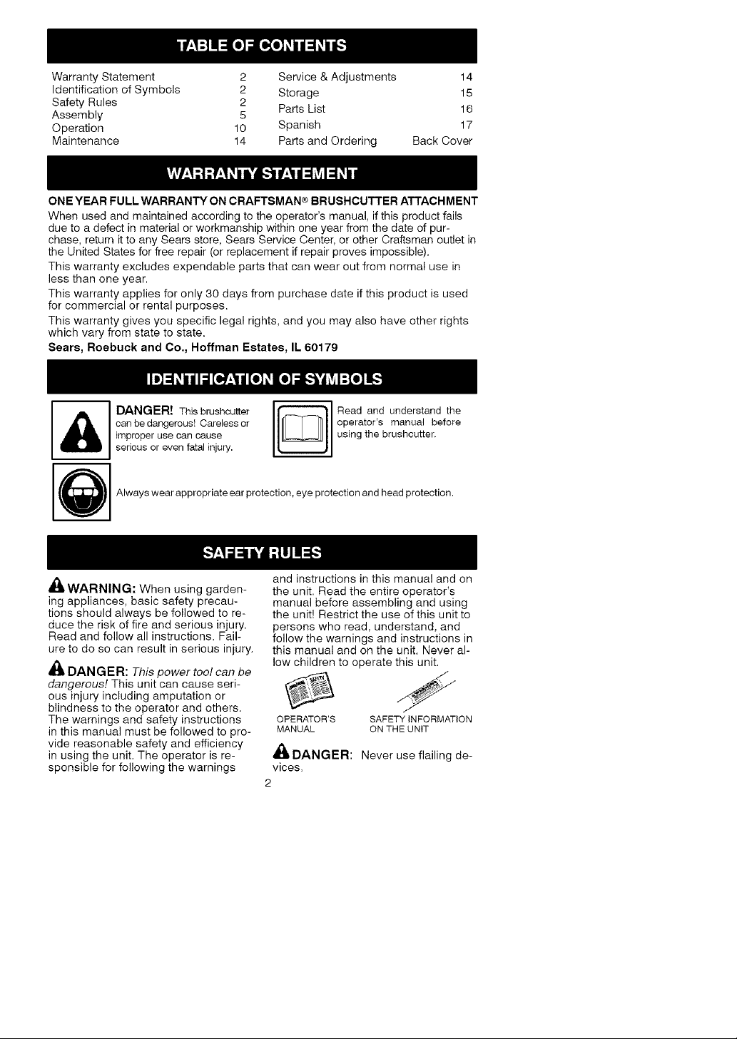
DANGER! This brushcutter
can be dangerous! Carelessor
improperuse can cause
seriousor evenfatal injury.
Always wear appropriate ear protection, eye protection and head protection.
_WARNING: When using garden-
ing appliances, basic safety precau-
tions should always be followed to re-
duce the risk of fire and serious injury.
Read and follow all instructions. Fail-
ure to do so can result in serious injury.
DANGER: This power tool can be
dangerous! This unit can cause seri-
ous injury including amputation or
blindness to the operator and others.
The warnings and safety instructions
in this manual must be followed to pro-
vide reasonable safety and efficiency
in using the unit. The operator is re-
sponsible for following the warnings
Read and understand the
operator's manual before
using the brushcutter.
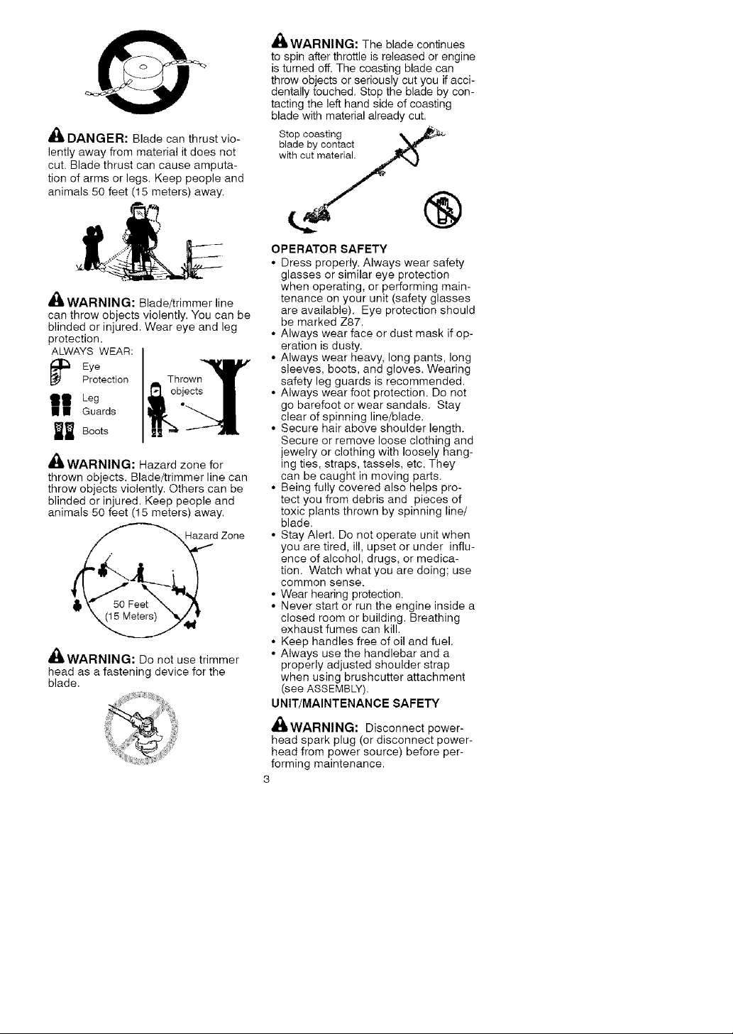
and instructions in this manual and on
the unit. Read the entire operator's
manual before assembling and using
the unit! Restrict the use of this unit to
persons who read, understand, and
follow the warnings and instructions in
this manual and on the unit. Never al-
low children to operate this unit.
OPERATOR'S SAFETY iNFORMATION
MANUAL QN THE UNIT
A
DANGER: Never use flailing de-
vices.
Page 3
_. DANGER: Blade can thrust vio-
lently away from material it does not
cut. Blade thrust can cause amputa-
tion of arms or legs. Keep people and
animals 50 feet (15 meters) away.
,1_ WARNING: Blade/trimmer line
can throw objects violently. You can be
blinded or injured. Wear eye and leg
protection.
ALWAYS WEAR:
Eye
Protection
II Leg
I I Guards
_ Boots
_WARNING: Hazard zone for
thrown objects. Blade/trimmer line can
throw objects violently. Others can be
blinded or injured. Keep people and
animals 50 feet (15 meters) away.
Hazard Zone
I,t
_.WARNING: Do not use trimmer
head as a fastening device for the
blade.
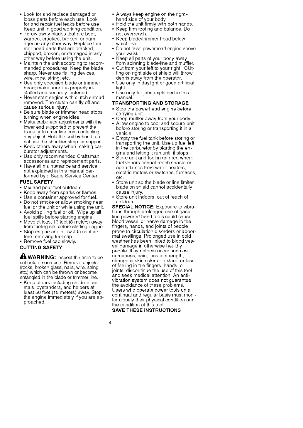
_, WARNING: The blade continues
to spin after throttle is released or engine
is turned off. The coasting blade can
throw objects or seriously cut you if acci-
dentally touched. Stop the blade by con-
tacting the left hand side of coasting
blade with material already cut.
bS,t°dPeC_yst'onngaot ._
with cut materi_
®
OPERATOR SAFETY
• Dress properly. Always wear safety
glasses or similar eye protection
when operating, or performing main-
tenance on your unit (safety glasses
are available). Eye protection should
be marked Z87.
• Always wear face or dust mask if op-
eration is dusty.
• Always wear heavy, long pants, long
sleeves, boots, and gloves. Wearing
safety leg guards is recommended.
• Always wear foot protection. Do not
go barefoot or wear sandals. Stay
clear of spinning line/blade.
• Secure hair above shoulder length.
Secure or remove loose clothing and
jewelry or clothing with loosely hang-
ing ties, straps, tassels, etc. They
can be caught in moving parts.
• Being fully covered also helps pro-
tect you from debris and pieces of
toxic plants thrown by spinning line/
blade.
• Stay Alert. Do not operate unit when
you are tired, ill, upset or under influ-
ence of alcohol, drugs, or medica-
tion. Watch what you are doing; use
common sense.
• Wear hearing protection.
• Never start or run the engine inside a
closed room or building. Breathing
exhaust fumes can kill.
• Keep handles free of oil and fuel.
• Always use the handlebar and a
properly adjusted shoulder strap
when using brushcutter attachment
(see ASSEMBLY).
UNIT/MAINTENANCE SAFETY
A_WARNING: Disconnect power-
head spark plug (or disconnect power-
head from power source) before per-
forming maintenance.
3
Page 4
• Lookforandreplacedamagedor
loosepartsbeforeeachuse.Look
forandrepairfuelleaksbeforeuse.
Keepunitingoodworkingcondition.
• Throwawaybladesthatarebent,
warped,cracked,broken,ordam-
agedinanyotherway.Replacetrim-
merheadpartsthatarecracked,
chipped,broken,ordamagedinany
otherwaybeforeusingtheunit.
• Maintaintheunitaccordingtorecom-
mendedprocedures.Keeptheblade
sharp.Neveruseflailingdevices,
wire,rope,string,etc.
• Useonlyspecifiedbladeortrimmer
head;makesureitisproperlyin-
stalledandsecurelyfastened.
• Neverstartenginewithclutchshroud
removed.Theclutchcanflyoffand
causeseriousinjury.
• Besurebladeortrimmerheadstops
turningwhenengineidles.
• Makecarburetoradjustmentswiththe
lowerendsupportedtopreventthe
bladeortrimmerlinefromcontacting
anyobject.Holdtheunitbyhand;do
notusetheshoulderstrapforsupport.
• Keepothersawaywhenmakingcar-
buretoradjustments.
• UseonlyrecommendedCraftsman
accessoriesandreplacementparts.
• Haveallmaintenanceandservice
notexplainedinthismanualper-
formedbyaSearsServiceCenter.
FUEL SAFETY
• Mix and pour fuel outdoors.
• Keep away from sparks or flames.
• Use a container approved for fuel.
• Do not smoke or allow smoking near
fuel or the unit or while using the unit.
• Avoid spilling fuel or oil. Wipe up all
fuel spills before starting engine.
• Move at least 10 feet (3 meters) away
from fueling site before starting engine.
• Stop engine and allow it to cool be-
fore removing fuel cap.
• Remove fuel cap slowly.
CUTTING SAFETY
WARNING: Inspect tile area to be
cut before each use. Remove objects
(rocks, broken glass, nails, wire, string,
etc.) which can be thrown or become
entangled in the blade or trimmer line.
• Keep others including children, ani-
mals, bystanders, and helpers at
least 50 feet (15 meters) away. Stop
the engine immediately if you are ap-
proached.
• Always keep engine on the right-
hand side of your body.
• Hold the unit firmly with both hands.
• Keep firm footing and balance. Do
not overreach.
• Keep blade/trimmer head below
waist level.
• Do not raise powerhead engine above
your waist.
• Keep all parts of your body away
from spinning blade/line and muffler.
• Cut from your left to your right. CUt-
ting on right side of shield will throw
debris away from the operator.
• Use only in daylight or good artificial
light.
• Use only for jobs explained in this
manual.
TRANSPORTING AND STORAGE
• Stop the powerhead engine before
carrying unit.
• Keep muffler away from your body.
• Allow engine to cool and secure unit
before storing or transporting it in a
vehicle.
• Empty the fuel tank before storing or
transporting the unit. Use up fuel left
in the carburetor by starting the en-
gine and letting it run until it stops.
• Store unit and fuel in an area where
fuel vapors cannot reach sparks or
open flames from water heaters,
electric motors or switches, furnaces,
etc.
• Store unit so the blade or line limiter
blade on shield cannot accidentally
cause injury.
• Store unit indoors, out of reach of
children.
SPECIAL NOTICE: Exposure to vibra-
tions through prolonged use of gaso-
line powered hand tools could cause
blood vessel or nerve damage in the
fingers, hands, and joints of people
prone to circulation disorders or abnor-
mal swellings. Prolonged use in cold
weather has been linked to blood ves-
sel damage in otherwise healthy
people. If symptoms occur such as
numbness, pain, loss of strength,
change in skin color or texture, or loss
of feeling in the fingers, hands, or
joints, discontinue the use of this tool
and seek medical attention. An anti-
vibration system does not guarantee
the avoidance of these problems.
Users who operate power tools on a
continual and regular basis must moni-
tor closely their physical condition and
the condition of this tool.
SAVE THESE INSTRUCTIONS
Page 5
CARTONCONTENTS
Checkcartoncontentsagainstthefol- Coupler
lowinglist. LOOSEN
Model358.792443
• Brushcutterattachment
• Handlebar
• Handlebarmountingbracketfor1"
(2.5cm)shaft
• Handlebarmountingbracketfor7/8" TIGHTEi', Knob
(2.2cm)shaft
• Bracketcover(2)
• Shoulderstrap
• Uppershoulderstrapclamp
• Lowershoulderstrapclamp(with
spacertabs)
• Handlebarbracketscrews(4)
• Shoulderstrapclampscrews(2)
• 4-pointweedblade(assembledon
brushcutterattachment)
• Largenutforinstallingblade
• Retainingwasher
• Cuppedwasher
• Metalshield(assembledonbrush-
cutterattachment)
• Trimmerhead
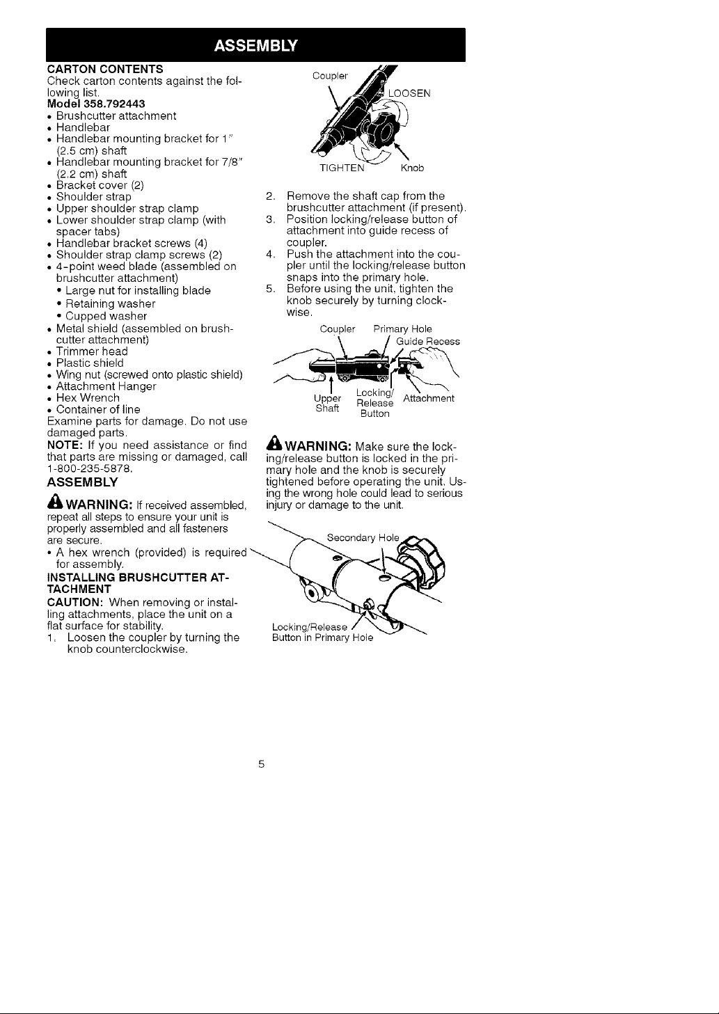
2. Removetheshaftcapfromthe
brushcutterattachment(ifpresent).
3. Positionlocking/releasebuttonof
attachmentintoguiderecessof
coupler.
4. Pushtheattachmentintothecou-
pleruntilthelocking/releasebutton
snapsintotheprimaryhole.
5. Beforeusingtheunit,tightenthe
knobsecurelybyturningclock-
wise.
Coupler Primary Hole
Guide Recess
• Plasticshield
• Wingnut(screwedontoplasticshield)
• AttachmentHanger Locking/
• HexWrench UpperReleaseAttachment
• Containerofline Shaft
Examinepartsfordamage.Donotuse
Button
damagedparts.
NOTE:Ifyouneedassistanceorfind
thatpartsaremissingordamaged,call
1-800-235-5878.
ASSEMBLY
_i WARNING:Ifreceivedassembled,
,_ WARNING: Make sure the lock-
ing/release button is locked in the pri-
mary hole and the knob is securely
tightened before operating the unit. Us-
ing the wrong hole could lead to serious
injury or damage to the unit.
repeatallstepstoensureyourunitis
properlyassembledandallfasteners
aresecure.
• A hex wrench (provided) is required'_
for assembly.
INSTALLING BRUSHCUTTER AT-
TACHMENT
CAUTION: When removing or instal-
ling attachments, place the unit on a
flat surface for stability. Locking/Release
1. Loosen the coupler by turning the Button in Primary Hole
knob counterclockwise.
Page 6
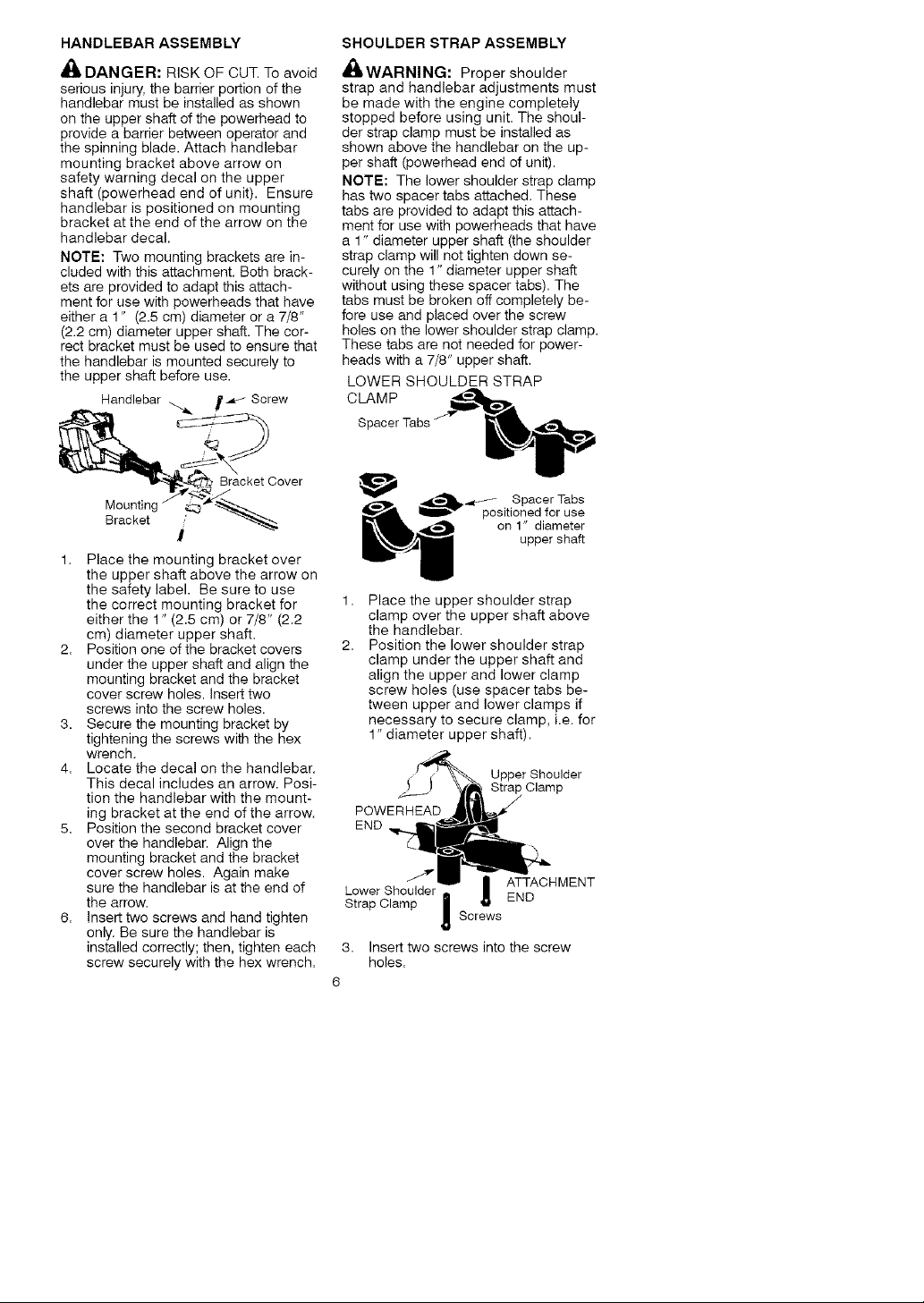
HANDLEBAR ASSEMBLY
,_ DANGER: RISK OF CUT. To avoid
serious injury, the barrier portion of the
handlebar must be installed as shown
on the upper shaft of the powerhead to
provide a barrier between operator and
the spinning blade. Attach handlebar
mounting bracket above arrow on
safety warning decal on the upper
shaft (powerhead end of unit). Ensure
handlebar is positioned on mounting
bracket at the end of the arrow on the
handlebar decal.
NOTE: Two mounting brackets are in-
cluded with this attachment. Both brack-
ets are provided to adapt this attach-
ment for use with powerheads that have
either a 1" (2.5 cm) diameter or a 7/8"
(2.2 cm) diameter upper shaft. The cor-
rect bracket must be used to ensure that
the handlebar is mounted securely to
the upper shaft before use.
Handlebar ._ J_ _ Screw
SHOULDER STRAP ASSEMBLY
_bWARNING: Proper shoulder
strap and handlebar adjustments must
be made with the engine completely
stopped before using unit. The shoul-
der strap clamp must be installed as
shown above the handlebar on the up-
per shaft (powerhead end of unit).
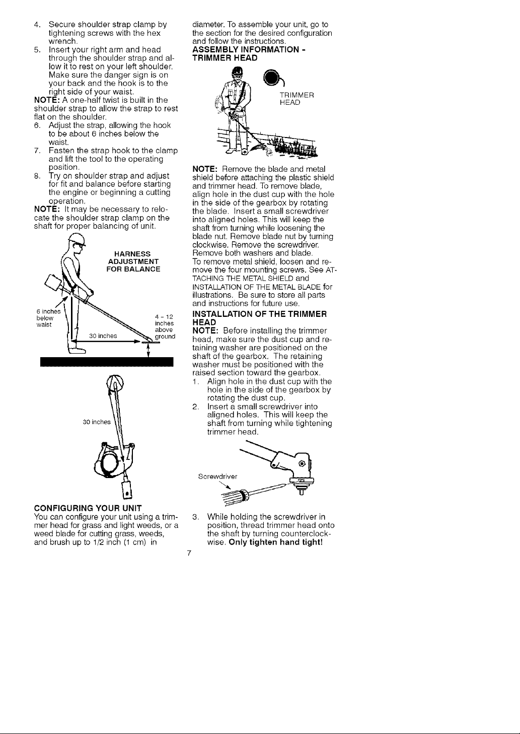
NOTE: The lower shoulder strap clamp
has two spacer tabs attached. These
tabs are provided to adapt this attach-
ment for use with powerheads that have
a 1" diameter upper shaft (the shoulder
strap clamp will not tighten down se-
curely on the 1" diameter upper shaft
without using these spacer tabs). The
tabs must be broken off completely be-
fore use and placed over the screw
holes on the lower shoulder strap clamp.
These tabs are not needed for power-
heads with a 7/8" upper shaft.
LOWER SHOULDER STRAP
CLAMP
_et Cover
Bracket .'
I
1. Place the mounting bracket over
the upper shaft above the arrow on
the safety label. Be sure to use
the correct mounting bracket for
either the 1" (2.5 cm) or 7/8" (2.2
cm) diameter upper shaft.
2. Position one of the bracket covers
under the upper shaft and align the
mounting bracket and the bracket
cover screw holes. Insert two
screws into the screw holes.
3. Secure the mounting bracket by
tightening the screws with the hex
wrench.
4. Locate the decal on the handlebar.
This decal includes an arrow. Posi-
tion the handlebar with the mount-
ing bracket at the end of the arrow.
5. Position the second bracket cover
over the handlebar. Align the
mounting bracket and the bracket
cover screw holes. Again make
sure the handlebar is at the end of
the arrow.
6. Insert two screws and hand tighten
only. Be sure the handlebar is
installed correctly; then, tighten each
screw securely with the hex wrench.
.,_L_L_ / Spacer Tabs
1,
Place the upper shoulder strap
clamp over the upper shaft above
the handlebar.
2.
Position the lower shoulder strap
clamp under the upper shaft and
align the upper and lower clamp
screw holes (use spacer tabs be-
tween upper and lower clamps if
necessary to secure clamp, i.e. for
1" diameter upper shaft).
POWERHEAD
END
Lower Shoulder | ATTACHMENT
Strap Clamp n _' END
3. Insert two screws into the screw
holes.
6
positioned for use
Screws
!
on 1" diameter
upper shaft
Strap Clamp
Page 7
4. Secureshoulderstrapclampby
tighteningscrewswiththehex
wrench.
5. Insertyourrightarmandhead
throughtheshoulderstrapandal-
lowittorestonyourleftshoulder.
Makesurethedangersignison
yourbackandthehookistothe
rightsideofyourwaist.
NOTE:Aone-halftwistisbuiltinthe
shoulderstraptoallowthestraptorest
flatontheshoulder.
6. Adjustthestrap,allowingthehook
tobeabout6inchesbelowthe
waist.
7. Fastenthestraphooktotheclamp
andliftthetooltotheoperating
position.
8. Tryonshoulderstrapandadjust
forfitandbalancebeforestarting
theengineorbeginningacutting
operation.
NOTE:Itmaybenecessarytorelo-
catetheshoulderstrapclamponthe
shaftforproperbalancingofunit.
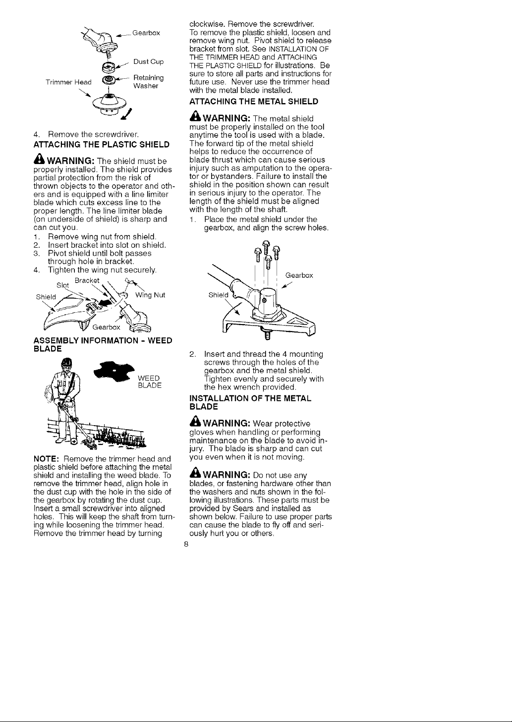
HARNESS
ADJUSTMENT
FOR BALANCE
6 inches
below 4 - 12
waist inches
30 i
above
ground
diameter. To assemble your unit, go to
the section for the desired configuration
and follow the instructions.
ASSEMBLY INFORMATION -
TRIMMER HEAD
._ TRIMMER
NOTE: Remove the blade and metal
shield before attaching the plastic shield
and trimmer head. To remove blade,
align hole in the dust cup with the hole
in the side of the gearbox by rotating
the blade. Insert a small screwdriver
into aligned holes. This will keep the
shaft from turning while loosening the
blade nut. Remove blade nut by turning
clockwise. Remove the screwdriver.
Remove both washers and blade.
To remove metal shield, loosen and re-
move the four mounting screws. See AT-
TACHING THE METAL SHIELDand
INSTALLATIONOF THE METAL BLADE for
illustrations. Be sure to store all parts
and instructions for future use.
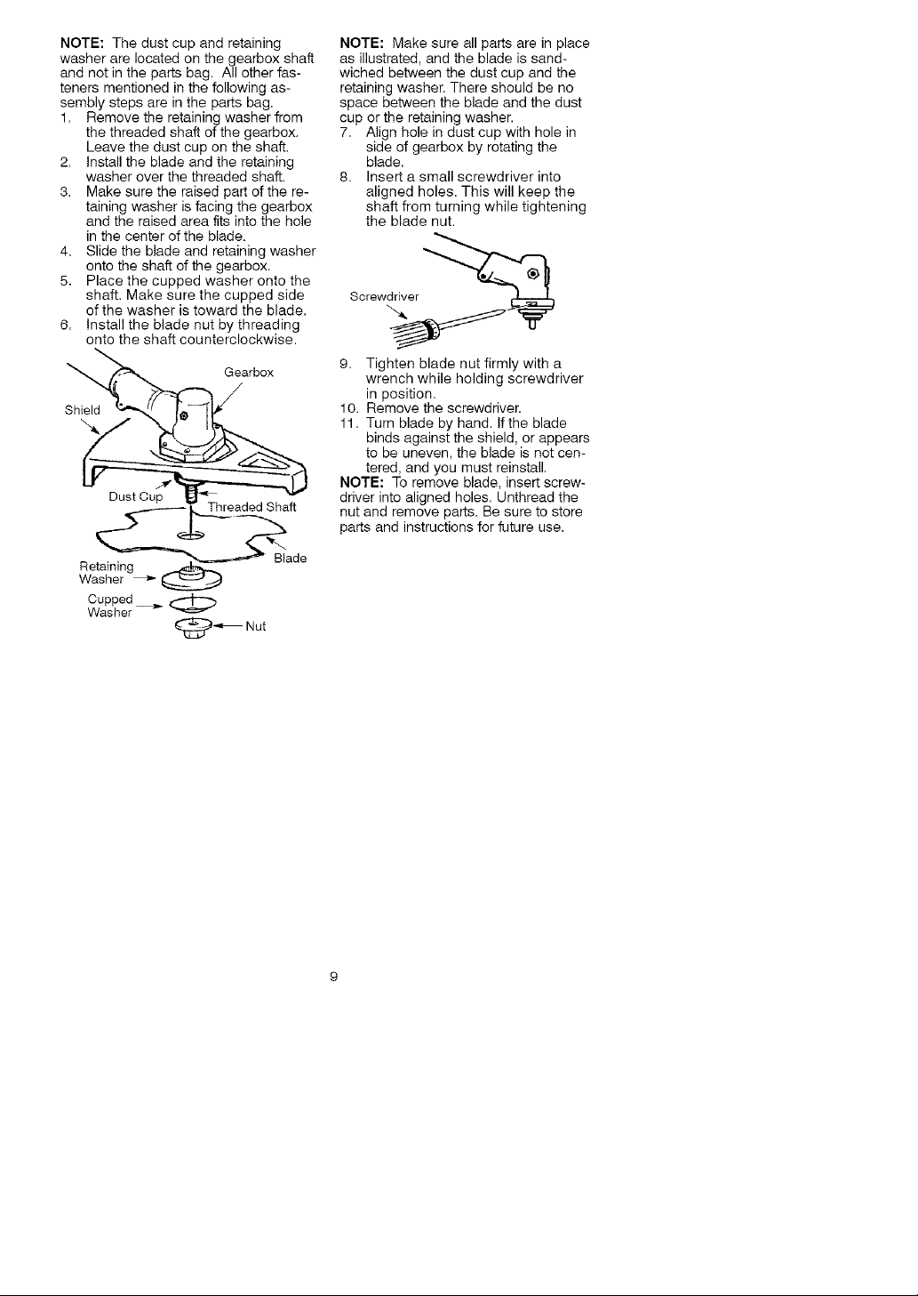
INSTALLATION OF THE TRIMMER
HEAD
NOTE: Before installing the trimmer
head, make sure the dust cup and re-
taining washer are positioned on the
shaft of the gearbox. The retaining
washer must be positioned with the
raised section toward the gearbox.
1. Align hole in the dust cup with the
hole in the side of the gearbox by
rotating the dust cup.
2. Insert a small screwdriver into
aligned holes. This will keep the
shaft from turning while tightening
trimmer head=
CONFIGURING YOUR UNIT
You can configure your unit using a trim-
mer head for grass and light weeds, or a
weed blade for cutting grass, weeds,
and brush up to 1/2 inch (1 cm) in
Screw._er _
3,
While holding the screwdriver in
position, thread trimmer head onto
the shaft by turning counterclock-
wise. Only tighten hand tight!
Page 8
.,___Gearbox
_ Dust Cup
Trimmer Head _ Retainh_g
Washer
4. Remove the screwdriver.
ATTACHING THE PLASTIC SHIELD
_ WARNING: The shield must be
properly installed. The shield provides
partial protection from the risk of
thrown objects to the operator and oth-
ers and is equipped with a line limiter
blade which cuts excess line to the
proper length. The line limiter blade
(on underside of shield) is sharp and
can cut you.
1. Remove wing nut from shield.
2. Insert bracket into slot on shield.
3. Pivot shield until bolt passes
through hole in bracket.
4. Tighten the wing nut securely.
Slot Bracket _:_
Shield Wing Nut
\
clockwise. Remove the screwdriver.
To remove the plastic shield, loosen and
remove wing nut. Pivot shield to release
bracket from slot. See INSTALLATIONOF
THE TRIMMER HEAD and Alq-ACHING
THE PLASTIC SHIELD for illustrations. Be
sure to store all parts and instructions for
future use. Never use the trimmer head
with the metal blade installed.
ATTACHING THE METAL SHIELD
,4(_,WARNING: The metal shield
must be properly installed on the tool
anytime the tool is used with a blade.
The forward tip of the metal shield
helps to reduce the occurrence of
blade thrust which can cause serious
injury such as amputation to the opera-
tor or bystanders. Failure to install the
shield in the position shown can result
in serious injury to the operator. The
length of the shield must be aligned
with the length of the shaft.
1. Place the metal shield under the
gearbox, and align the screw holes.
_ Gearbox
Shiek
\
Gearbox
ASSEMBLY INFORMATION - WEED
BLADE
_' WEED
BLADE
NOTE: Remove the trimmer head and
plastic shield before attaching the metal
shield and installing the weed blade. To
remove the trimmer head, align hole in
the dust cup with the hole in the side of
the gearbox by rotating the dust cup.
Insert a small screwdriver into aligned
holes. This will keep the shaft from turn-
ing while loosening the trimmer head.
Remove the trimmer head by turning
2. Insert and thread the 4 mounting
screws through the holes of the
gearbox and the metal shield.
Tighten evenly and securely with
the hex wrench provided.
INSTALLATION OF THE METAL
BLADE
WARNING: Wear protective
gloves when handling or performing
maintenance on the blade to avoid in-
jury. The blade is sharp and can cut
you even when it is not moving.
_WARNING: Do not use any
blades, or fastening hardware other than
the washers and nuts shown in the fol-
lowing illustrations. These parts must be
provided by Sears and installed as
shown below. Failure to use proper parts
can cause the blade to fly off and seri-
ously hurt you or others.
8
Page 9
NOTE:Thedustcupandretaining
washerarelocatedonthegearboxshaft
andnotinthepartsbag.Allotherfas-
tenersmentionedinthefollowingas-
semblystepsareinthepartsbag.
1. Removetheretainingwasherfrom
thethreadedshaftofthegearbox.
Leavethedustcupontheshaft.
2. Installthebladeandtheretaining
washeroverthethreadedshaft.
3. Makesuretheraisedpartofthere-
tainingwasherisfacingthegearbox
andtheraisedareafitsintothehole
inthecenteroftheblade.
4. Slidethebladeandretainingwasher
ontotheshaftofthegearbox.
5. Placethecuppedwasherontothe
shaft.Makesurethecuppedside
ofthewasheristowardtheblade.
6. Installthebladenutbythreading
ontotheshaftcounterclockwise.
Gearbox
Shield
Dust Cup
Retaining pE_lt_,_..
Washer _
Cupped
Washer
_ Nut
de
NOTE: Make sure all parts are in place
as illustrated, and the blade is sand-
wiched between the dust cup and the
retaining washer. There should be no
space between the blade and the dust
cup or the retaining washer.
7. Align hole in dust cup with hole in
side of gearbox by rotating the
blade.
8. Insert a small screwdriver into
aligned holes. This will keep the
shaft from turning while tightening
the blade nut.
Screwdriver _
9. Tighten blade nut firmly with a
wrench while holding screwdriver
in position.
10. Remove the screwdriver.
11. Turn blade by hand. If the blade
binds against the shield, or appears
to be uneven, the blade is not cen-
tered, and you must reinstall.
NOTE: To remove blade, insert screw-
driver into aligned holes. Unthread the
nut and remove parts. Be sure to store
parts and instructions for future use.
Page 10
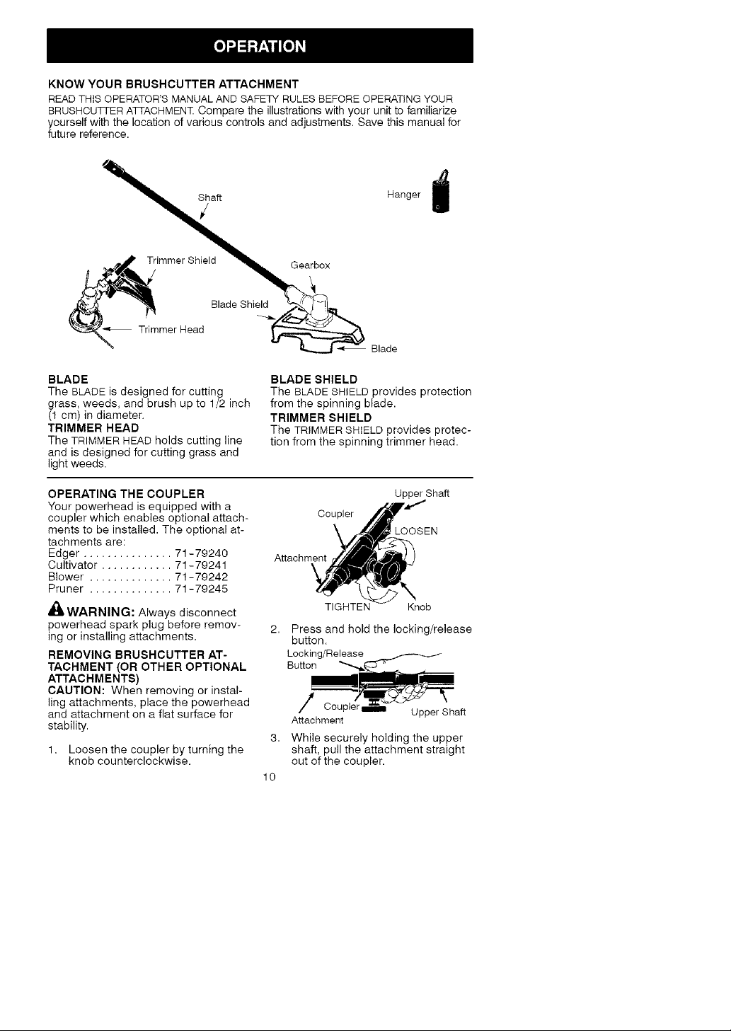
KNOWYOURBRUSHCUTTER ATTACHMENT
READ THiS OPERATOR'S MANUAL AND SAFETY RULES BEFORE OPERATING YOUR
BRUSHCUTI-ERATTAOHMENT Compare the illustrations with your unit to familiarize
yourself with the location of various controls and adjustments. Save this manual for
future reference.
Hanger j
immerShield _
B,adeBhied
Heo B'adeBh% B,ade
BLADE
The BLADE is designed for cutting
grass, weeds, and brush up to 1/2 inch
(1 cm) in diameter.
TRIMMER HEAD
The TRIMMER HEAD holds cutting line
and is designed for cutting grass and
light weeds.
OPERATING THE COUPLER
Your powerhead is equipped with a
coupler which enables optional attach-
ments to be installed. The optional at-
tachments are:
Edger ............... 71-79240
Cultivator ............ 71-79241
Blower .............. 71-79242
Pruner .............. 71-79245
_. WARNING: Always disconnect
powerhead spark plug before remov-
ing or installing attachments.
REMOVING BRUSHCUTTER AT-
TACHMENT (OR OTHER OPTIONAL
ATTACHMENTS)
CAUTION: When removing or instal-
ling attachments, place the powerhead
and attachment on a flat surface for
stability.
1= Loosen the coupler by turning the
knob counterclockwise.
BLADE SHIELD
The BLADE SHIELD provides protection
from the spinning blade.
TRIMMER SHIELD
The TRIMMER SHIELD provides protec-
tion from the spinning trimmer head.
Upper Shaft
Coupler
LOOSEN
Attachment
TIGHTEiX Knob
Press and hold the locking/release
button.
Locking/Release
Button ""-,.,_ _---._
Attachment
3,
While securely holding the upper
shaft, pull the attachment straight
out of the coupler.
10
Page 11

INSTALLINGOPTIONAL ATTACH-
MENT
1. Remove the shaft cap from the at-
tachment (if present) and discard.
2. Position locking/release button of
attachment into guide recess of
upper shaft coupler.
3. Push the attachment into the cou-
pler until the locking/release button
snaps into the primary hole.
4. Before using the unit, tighten the
knob securely by turning clockwise.
Coupler Primary Hole
Upper Locking/ Attachment
Shaft Release
,_ WARNING: Make sure the lock-
ing/release button is locked in the pri-
mary hole and the knob is securely
tightened before operating the unit. Us-
ing the wrong hole could lead to serious
injury or damage to the unit.
Secondary Hoie
Locking/Release
Button in Primary HoIe
INSTALLING ATTACHMENT
HANGER
An attachment hanger is provided for
storage when attachment is not in use.
To install hanger on attachment:
1. Remove the shaft cap from the at-
tachment (if present) and discard.
2. Press and hold the locking/release
button.
3. Push hanger onto the attachment
until the locking/release button
snaps into the hole.
OPERATING POSITION
ALWAYS WEAR:
Heavy,
Long Pants
Button
Guide Recess
Eye Protection
Cut from
your left to
your right,
NOTE: This brushcutter attachment is
not designed for use with electric pow-
erheads.
When operating unit with brushcutter
attachment, clip shoulder strap onto
upper shoulder strap clamp, stand as
shown and check for the following:
• Wear eye protection and heavy
clothing.
• Keep arms extended with right hand
holding the trigger handle of power-
head.
• Keep left arm extended with left hand
holding the handlebar.
• Keep unit below waist level.
• Shoulder strap pad should be cen-
tered on your left shoulder and dan-
ger sign centered on your back.
• Maintain full weight of tool on left
shoulder.
• Without bending over, keep the blade
near and parallel to the ground and
not crowded into material being cut.
OPERATING INSTRUCTIONS FOR
USE OF BRUSHCUTTER ATTACH-
MENT WITH TRIMMER HEAD
WARNING: Always wear eye
protection. Never lean over tile trimmer
head. Rocks or debris can ricochet or
be thrown into eyes and face and
cause blindness or other serious injury.
Before trimming, bring engine to a
speed sufficient to cut material to be
trimmed.
Do not run the engine at a higher speed
than necessary. The cutting line will cut
efficiently when the engine is run at less
than full throttle. At lower speeds, there
is less engine noise and vibration. Al-
ways release the throttle trigger and
allow the engine to return to idle speed
when not cutting.
CUTTING METHODS
,_WARNING: Use minimum speed
and do not crowd the line when cutting
around hard objects (rock, gravel,
fence posts, etc.), which can damage
the trimmer head, become entangled
in the line, or be thrown causing a seri-
ous hazard.
• The tip of the line does the cutting.
You will achieve the best perform-
ance and minimum line wear by not
crowding the line into the cutting
area. The right and wrong ways are
shown below.
11
Page 12

Tip of line does the
Right
Line crowded into
wor__
Wrong
• The line will easily remove grass and
weeds from around walls, fences,
trees and flower beds, but it also can
cut the tender bark of trees or shrubs
and scar fences.
• For trimming or scalping, use less
than full throttle to increase line life
and decrease head wear, especially:
• During light duty cutting.
• Near objects around which the line
can wrap such as small posts,
trees or fence wire.
• For mowing or sweeping, use full
throttle for a good clean job.
TRIMMING - Hold the bottom of the
trimmer head about 3 inches (8 cm)
above the ground and at an angle. Allow
only the tip of the line to make contact.
Do not force trimmer line into work
area,
Trimming
3 inches
(8 cm) abow
ground
SCALPING - The scalping technique
removes unwanted vegetation down to
the ground. Hold the bottom of the
trimmer head about 3 inches (8 cm)
above the ground and at an angle. Al-
low the tip of the line to strike the
ground around trees, posts, monu-
ments, etc. This technique increases
line wear.
Scalping
MOWING - Your trimmer is ideal for
mowing in places conventional lawn
mowers cannot reach. In the mowing
position, keep the line parallel to the
ground. Avoid pressing the head into
the ground as this can scalp the
ground and damage the tool.
Mowing
SWEEPING - The fanning action of the
rotating line can be used to blow away
loose debris from an area. Keep the line
parallel to and above the area surface
and swing the tool from side to side.
Sweeping
OPERATING INSTRUCTIONS FOR
USE OF BRUSHCUTTER ATTACH-
MENT WITH WEED BLADE
• Blade Thrust is a reaction that only
occurs when using a bladed unit. This
reaction can cause serious injury such
as amputation. Carefully study this
section. It is important that you under-
stand what causes blade thrust, how
you can reduce the chance of its oc-
curring, and how you can remain in
control of unit if blade thrust occurs.
• WHAT CAUSES BLADE THRUST -
Blade Thrust can occur when spin-
ning blade contacts an object that it
does not cut. This contact causes
blade to stop for an instant and then
suddenly move or "thrust" away from
object that was hit. The "thrusting" re-
action can be violent enough to cause
operator to be propelled in any direc-
tion and lose control of unit. The un-
controlled unit can cause serious injury
if blade contacts operator or others.
• WHEN BLADE THRUST OCCURS
- Blade Thrust can occur without
warning if the blade snags, stalls, or
binds. This is more likely to occur in
12
Page 13

areaswhereitisdifficulttoseethe
materialbeingcut.Byusingtheunit
properly,theoccurrenceofblade
thrustwillbereducedandtheopera-
torwillbelesslikelytolosecontrol.
• Cutonlygrass,weeds,andwoody
brushupto1/2inch(1cm)indiameter
withweedblade.Donotletbladecon-
tactmaterialitcannotcutsuchas
stumps,rocks,fences,metal,etc.,or
clustersofhard,woodybrushwitha
diametergreaterthan1/2inch(1cm).
• Useasharpblade.Adullbladeis
morelikelytosnagandthrust.
• Cutonlyatfullthrottle.Thebladewill
havemaximumcuttingpowerandis
lesslikelytobindorstall.
• "Feed"thebladedeliberatelyandnot
toorapidly.Thebladecanthrust
awayifitisfedtoorapidly.
• Cutonlyfromyourlefttoyourright.
Cuttingonrightsideoftheshieldwill
throwdebrisawayfromtheoperator.
• Usetheshoulderstrapandkeepa
firmgripontheunitwithbothhands.
Aproperlyadjustedshoulderstrap
willsupporttheweightoftheunit,
freeingyourarmsandhandstocon-
trolandguidethecuttingmotion.
• Keepfeetcomfortablyspreadapart
andbracedforapossiblesudden,
rapidthrustofunit.Donotoverreach.
Keepfirmfootingandbalance.
• Keepbladebelowwaistlevel.Itwill
beeasiertomaintaincontrolofunit.
• Donotraisetheengineaboveyour
waistasthebladecancomedanger-
ouslyclosetoyourbody.
• Donotswingtheunitwithsuchforce
thatyouareindangeroflosingyour
balance.
Bringthepowerheadenginetocutting
speedbeforeenteringthematerialto
becut.
Ifthebladedoesnotturnwhenyou
squeezethethrottletriggerofthepow-
erhead,makesuretheattachmentis
fullyinsertedintothecoupler.
Alwaysreleasethethrottletriggerand
allowpowerheadenginetoreturnto
idlespeedwhennotcutting.Theblade
shouldnotturnwhiletheengineisrun-
ningatidle.Ifthebladeturnsatidle,
donotuseyourunit.RefertotheCAR-
BURETORADJUSTMENTsectionofthe
powerheadmanualorcontactyour
SearsServiceCenter.
• Maintaingoodfirmfootingwhileus-
ingtheunit.Dothisbyplantingfeet
firmlyinacomfortableapartposition.
•Cutwhileswingingtheupperpartof
yourbodyfromlefttoright.
•Asyoumoveforwardtothenext
areatocut,besuretomaintainyour
balance,andfooting.
RECOMMENDEDCUTTINGPOSITION
O'ClOC_
Cutusingthe2 _.41"_._,_...,_... 2
o'ctock to 4 o'clock
position of the _ __ %"€'4o'clock
blade
V't'f'I/.'
"IV
_i, WARNING: The operator or oth-
ers must not try to clear away cut ma-
terial with the engine running or the
blade turning to avoid serious injury.
Stop engine and blade before remov-
ing materials wrapped around blade or
shaft.
13
Page 14

MAINTENANCE SCHEDULE
_IWARNING: Always stop unit and disconnect spark plug wire before
performing maintenance.
CARE AND MAINTENANCE TASK
Check for loose fasteners and parts
Check for damaged or worn parts
Inspect and clean unit and decals
Check or replace blade
GENERAL RECOMMEN DATIONS
The warranty on this attachment does
not cover items that have been sub-
jected to operator abuse or negli-
gence. To receive full value from the
warranty, the operator must maintain
the brushcutter attachment as instruct-
ed in this manual.
CHECK FOR DAMAGED OR
WORN PARTS
Contact Sears Service Center for re-
placement of damaged or worn parts.
• Blade Shield - Discontinue use of
brushcutter attachment if shield is
damaged.
• CHECK FOR LOOSE
FASTENERS AND PARTS
• Blade nut
• Fasteners
INSPECT AND CLEAN UNIT
AND DECALS
• After each use, inspect complete unit
for loose or damaged parts. Clean
the unit and decals using a damp
WHEN TO PERFORM
Before each use
Before each use
After each use
Every 5 hours of operation
• Wipe off unit with a clean dry cloth.
BLADE MAINTENANCE
_ WARNING: The blade will contin-
ue to spin after the engine stops or af-
ter the throttle trigger has been re-
leased. To avoid serious injury, make
sure the blade has stopped coasting
and disconnect the spark plug before
performing work on the blade.
,_ WARNING: Always replace a
blade that is bent, warped, cracked,
broken, or damaged in any other way.
Never attempt to straighten and reuse
a damaged blade. Use only specified
replacement blade. Wear protective
gloves when handling or performing
maintenance on the blade to help
avoid injury.
• Check blade for flatness periodically.
Lay the blade on a flat surface to in-
spect for flatness. Throw away a
blade that is not flat.
cloth with a mild detergent.
LINE REPLACEMENT
• Always use Craftsman replacement
line.
Choose the line size best suited for the
job at hand. Red line is designed for
cutting grass and small weeds. The
black colored line is designed for cut-
ting larger weeds and light brush.
NOTE: Before inserting new line into
the holes in the cutting head, identify
the proper holes. Follow directions as
shown on the line glide plate.
1. Remove the old line and line glide
plate from the cutting head.
2. Clean entire surface of cutting
head.
3. Reinstall line glide plate (see il-
lustration). Align arrow with:
(_ when using medium (red) or
large (black)line
when using lines with diameter
(_) smaller than medium (red) line
(optional)
Line glide Arrow
Trimmer head
14
Page 15

NOTE:Lineglideplatemustberein-
stalledincuttingheadbeforeinserting
newline.
4. Insertbothendsofyourline
throughtheproperholesinthe
sideofthecuttinghead.
!
Positioning
Tunnel
6. Correctly installed line will be the
same length on both ends.
REPLACING THE CUTTING HEAD
1. Align hole in tile dust cup with tile
hole in the side of the gearbox by
rotating the dust cup.
2. Insert a small screwdriver into
aligned holes. This will keep the
shaft from turning while removing
and installing trimmer head.
Ssrew ,er
5, Pull the line and make sure the
line is against the hub and ex-
tended full through the positioning
tunnels.
Positioning
Tunnel \
A
411 WARNING: Perform the following
steps after each use:
• Allow attachment and gearbox to
cool before storing or transporting.
• Store attachment with blade shield in
place. Position attachment so that
any sharp object cannot accidentally
cause injury.
• Store the attachment in a dry, well
ventilated area out of the reach of
children.
SEASONAL STORAGE
Prepare attachment for storage at end
of season or if it will not be used for 30
days or more.
If your brushcutter attachment is to be
stored for a period of time:
Line against
3. While holding the screwdriver in
position, remove trimmer head by
turning clockwise.
4. Thread replacement trimmer head
onto the shaft by turning counterclock-
wise. Only tighten hand tightt
5. Remove the screwdriver.
BLADE REPLACEMENT
Refer to the ASSEMBLY section for
blade replacement instructions and il-
lustrations=
• Clean the entire attachment.
• Inspect the blade shield area and
clean any dirt, grass, leaves, or de-
bris that has collected. Inspect the
blade and blade shield; replace a
blade that is bent, warped, cracked,
broken or damaged in any other way.
• Lightly oil external metal surfaces.
• Apply a coating of oil to the entire
surface of the blade; wrap it in heavy
paper or cloth.
• Check entire attachment for loose
screws or nuts= Replace any dam-
aged, worn or broken parts.
• At the beginning of the next season,
use only fresh fuel having the proper
gasoline to oil ratio.
15
Page 16

Declaraci6ndeGarantia 17 Mantenimiento 30
Identificaci6ndeSimbolos 17 ServicioyAjustes 31
ReglasdeSeguridad 17 Almacenaje 32
Montaje 20 ListadePiezas 16
Uso 26 RepuestoyEncargosContratapa
UNAI_IO COMPLETO DE GARANTiA PARA LA CORTADORA DE MALEZAS
ACCESORIO CRAFTSMAN ®
Si este producto falla por un defecto en el material o de mano de obra dentro del
a_o a partir de la fecha de compra y este se ha utilizado y mantenido de acuerdo
al manual del usuario, envielo a cualquier tienda Sears, Centro de Servicios
Sears u otra tienda Craftsman en los Estados Unidos para su reparaci6n gratuita
(o reemplazo si no es posible repararlo).
Esta garantia excluye las partes desechables que se pueden desgastarse al
usarlas normalmente en menos de un a_o.
Esta garantia es aplicable per s61o 30 dias desde la fecha de compra si este pro-
ducto se usa con fines comerciales o se usa para arriendo.
Esta garantia le otorga derechos legales especificos, y usted tambien puede
tener otros derechos que varian de estado a estado.
Sears, Roebuck and Co., Hoffman Estates, IL 60179
PELIGRO: iEsta cortadora
demalezas puede serpeligrosa!
El uso descuidado o indebido de
esta herramienta puede causar
graves o at_nheridas fatales!
Use siempre la proteccion de oidos apropiada, Ia proteccion de
ojos y la protecci6n de la cabeza.
ADVERTENCIA: AI usar cualqui-
er herramienta de fuerza de jardineria,
deber&n observarse precauciones b&si-
cas de seguirdad en todo momento
para reducir el riesgo de incendio y
graves heridas. Lea y cumpla con todas
las instrucciones. Su incumplimiento
puede ocasionar lesiones graves.
PELIGRO: iEsta herramienta mo-
torizada puede ser peligrosa! Puede
ocasionar lesiones graves, incluso la
amputaci6n o la ceguera, tanto al opera-
dor como a otras personas. Las adver-
tencias e instrucciones de seguridad
contenidas en este manual deben cum-
plirse en redo momento para garantizar
Lea y comprenda eI
manual de1 usuado
antes de usar la corta-
dora de malezas.
un nivel de seguridad y efectividad ra-
zonable durante la utilizaci6n del apara-
to. El operador es responsable del
cumplimiento de las advertencias e
instrucciones indicadas en este manual
yen el aparato. Antes de ensamblar y
utilizar el aparato, lea integramente el
manual del usuario. Limite el uso de
este aparato a personas que previa-
mente hayan leido y comprendido, y
posteriormente cumplan, las adverten-
cias e instrucciones indicadas en este
manual yen el aparato. Nunca permita
que este aparato sea utilizado por niSos.
17
Page 17

MANUAL DEL INFORMACION DE
USUARIO SEGURIDAD DEL
APARATQ
Zona
peligro
PEMGRO: Nunca use dispositivos
desgranadores.
PELIGRO: La cuchilla puede rebo-
tar violentamente en materiales que no
puede cortar. Los rebotes de la cuchilla
pueden causar la amputaci6n de brazos
o piernas. Mantenga a personas y anima-
les lejos de la herramienta (15 metros).
ADVERTENClA: La cuchilla/
linea de corte puede despedir objetos
violentamente. Esto puede ocasionade
ceguera o lesiones. Prot6jase los ojos
y las piernas.
UTILICE SIEMPRE:
Protecci6n _
ocular
I1|
• • Perneras
Botas _
_,ADVERTENClA: Zona de peligro
de objetos despedidos. La cuchilla/linea
de corte puede despedir objetos violen-
tamente. Esto puede ocasionar ceguera
o lesiones a otros. Mantenga a perso-
nas y animales lejos de la herramienta
15 metros (50 pies).
Objetos
despedidos
o
1,1
_IkADVERTENClA: No utilice el ca-
bezal de corte come dispositivo de su-
jeci6n de la cuchilla.
,d_ ADVERTENClA: La cuchilla si-
gue girando incluso despu6s de soltar
el acelerador o de apagar el motor. In-
cluso cuando est& girando libremente,
la cuchilla puede despedir objetos o
causar cortes profundos si se toca ac-
cidentalmente. Detenga la cuchilla po-
niendo en contacto el lado izquierdo
de la misma con material ya cortado.
Para detener Ia cuchi- _ _
Ila cuando gire libre- "_t r
mente, p6ngata en ._'_
contacto con material J
previamente corta6_
®
SEGURIDAD DEL OPERADOR
• Vistase apropiadamente. Siempre
use anteojos de seguridad o similar
protecci6n para los ojos cuando use
o d6 mantenimiento a este aparato
(anteojos de seguridad est&n dispo-
nibles). La protecci6n para los ojos
debe ser marcada con Z87.
• Siempre utilize mascarilla para la
cara o mascarilla a prueba de polvo
si se va a trabajar en condiciones
donde hay polvo.
• Siempre utilize pantalones pesados
y largos, mangas largas, botas y
guantes. Se recomienda el uso de
pantorrilleras de seguridad.
• Siempre utilize protecci6n para los
pies. No trabaje descalzo ni en
sandalias. Evite la cuchilla/linea de
corte girante.
18
Page 18

• Mantengaelcabelloporencimade
loshombros,at&ndoloparatalefecto
siesnecesario.Nouseropasueltani
ropaconcorbatas,tiras,borlas,etc.
quecuelganlibremente.Puedenenre-
darseenlaspiezasenmovimiento.
• Siest&completamenttapado,estar&
m&sprotegidodelosescombrosy
pedazosdeplantast6xicosarroja-
dosparlacuchillagirante.
• Mant6ngasealerta.Nohagausadel
aparatoestandocansado,enfermo,
trastornadoobajolainfluenciadel
alcohol,dedrogasoderemedios.
VigilebienIoqueest&haciendo;use
delsentidocomQn.
• Useprotecci6ndeoidos.
• Nuncapongaelaparatoenmarcha
niIodejeenmarchadentrodeun
recintocerrado.Respirarlosvapores
delcombustibleIopuedematar.
• Mantengalasmanijaslibresde
aceiteydecombustible.
• Utilicesiempreelmangoyuna
correaparahombrecorrectamente
ajustadaalusarlacortadorade
malezasaccesorio(veaMONTAJE).
MANTENIMIENTO Y SEGURIDAD
DEL APARATO
_ADVERTENCIA: Desconecte la
buj[a (o desconecte aparato de la cor-
riente el6ctrica) antes de hacer cualqu-
ier mantenimiento.
• Antes de cada uso, busque las piezas
daSadas o sueltas y sustitOyalas. An-
tes de cada uso, busque posibles fu-
gas de combustible y, en su caso, re-
p&relas. Mantenga el aparato en buen
estado de funcionamiento.
• Deseche la cuchillas dobladas, den-
tadas, partidas, rotas o deterioradas
de algQn modo. Antes de utilizar la
unidad, sustituya las piezas del ca-
bezal de corte que esten partidas,
rotas o deterioradas de algOn modo.
• Realice el mantenimiento del aparato
siguiendo los procedimientos reco-
mendados. Mantenga la cuchilla afila-
da. Nunca utilice dispositivos desgra-
nadores, cable, cuerda, alambre, etc.
• Utilice exclusivamente la cuchilla o el
cabezal de corte especificado y ase-
g0rese de que est6 correctamente
instalado y firmemente sujeto.
• Nunca ponga en marcha el motor
con el cubierta del embrague des-
montado. El embrague podria des-
prenderse y causar graves lesiones.
• AsegQrese de que el cuchilla o el
cabezal de corte se detiene al pasar
el motor al ralent[.
• Realice los ajustes del carburador
con la parte inferior apoyada en alto
para impedir que la cuchilla entren
en contacto con alg0n objeto. Sujete
el aparato con las manos, sin utilizar
la correa al hombre.
• Cuando realice ajustes en el carbu-
rador, mantenga alejadas del lugar a
otras personas.
• Utilice exclusivamente los accesorios
y recambios recomendados por
Craftsman.
• Confie todas las tareas de manteni-
miento y reparaci6n no explicadas
en este manual a su Centre de
Servicio de Sears.
SEGURIDAD CON EL COMBUS-
TIBLE
• Mezcle y vierta el combustible en
exteriores.
• Mantenga el combustible alejado de
chispas y llamas.
• Utilice recipientes homologados para
el usa de combustibles.
• Impida que se fume cerca del com-
bustible o del aparato, tanto si este se
encuentra parado o se est& utilizando.
• Antes de poner en marcha el motor,
limpie todo posible resto de combus-
tible derramado.
• Antes de porter en marcha el motor,
al6jese coma minimo 3 metros del lu-
gar de repostaje.
• Antes de quitar el tap6n de combusti-
ble, detenga el motor y d6jelo enfriar.
• Remueva la tapa del tanque de com-
bustible lentamente.
SEGURIDAD AL CORTAR
_& ADVERTENCIA: Antes de cada
uso, inspeccione la zona de trabajo.
Retire todos los objetos (rocas, cris-
tales rotos, clavos, cables, hilos, etc.)
que puedan ser despedidos o quedar
enredados en la cuchilla.
• Mantenga alejados del lugar de tra-
bajo (15 metros) a otras personas,
ya sean niSos, acompaSantes o ayu-
dantes, y a animales. Detenga el
motor tan pronto como alguien se le
aproxime.
• Mantenga siempre el motor junto al
lado derecho de su cuerpo.
• Sujete firmemente la unidad con am-
bas manos.
• Pise con seguridad y mantenga el
equilibrio en todo memento. No esti-
re el cuerpo en exceso.
• Mantenga la cuchilla par debajo de
la cintura.
• No levante el cabeza de motor par en-
cima de su cintura.
19
Page 19

• Mantengatodaslaspartesdesu
cuerpoalejadasdelacuchillaydel
silenciador.
• Cortesiempredeizquierdaaderecha.
Sisecortaconlalineadelladodere-
chodelprotector,losescombrosvo-
lar&nensentidoopuestoalusuario.
• Useelaparato0nicamentedediao
enluzartificialfuerte.
• Utiliceelaparatosolamenteparalas
tareasexplicadasenestemanual.
TRANSPORTE Y ALMACENAMIENTO
• Antes de proceder a su transporte,
detenga el cabeza de motor.
• Mantenga el silenciador alejado del
cuerpo.
• Antes de almacenar o transportar el
aparato en un vehiculo, deje enfriar
el motor y sujete bien el aparato.
• Antes de guardar o transportar el
aparato, vacie el dep6sito de com-
bustible. Arranque el motor y d6jelo
en marcha hasta que se detenga
con el fin de agotar el combustible
que pueda quedar en el carburador.
• Guarde el aparato y el combustible
en un lugar donde los vapores ema-
nados del combustible no puedan
entrar en contacto con chispas ni lla-
mas procedentes de calentadores
de agua, motores o interruptores
el_ctricos, hornos, etc.
• Guarde el aparato de modo que la
cuchilla no puedan ocasionar lesio-
nes accidentalmente.
• Guarde el aparato dentro, fuera del
alcance de los hi,as.
NOTA ESPECIAL: El estar expuesto a
lae vibraciones a tray,s del uso prolon-
gado de herramientae de fuerza a gaso-
lina puede cuasar daSoe a los vasos
sanguineos o a los nervioe de los de-
doe, las manoe y las coyunturae en
aquellas personas que tienen propenei-
dad a los trastomos de la circulaci6n o a
lae hinchazones anormales. El uso pro-
Iongado en tiempo frio ha sido asociado
con daSos a los vaeos snaguineoe de
personas que por otra parte ee encuen-
tran en perfecto eetado de salud, Si
ocurren sintomas tales como el entume-
cimiento, el dolor, la falta de fuerza, los
cambioe en el color o la textura de la
piel o falta de sentido en los dedos, lae
manoe o las coyunturas, deje de usar
esta m&quina inmediatamente y procure
atenci6n medica. Los sistemae de anti-
vibraci6n no garantizan que ee eviten
tales problemes. Los usuarios que ha-
cen uso continuo y prolongando de las
herramientae de fuerza deben fiscalizar
atentamente su estado fisico y el estado
del aparato.
GUARDE ESTAS INSTRUCClONES
CONTENIDO DE LA CAJA
Use la siguiente lista para verificar que
todas la piezas hayan sido incluido:
Model 358.792443
• Cortadora de malezas accesorio
• Mango
• Soporte del mango para eleje de 1 pul-
gada (2,5 cm)
• Soporte del mango para el eje de 2,2
cm (7/8 de pulgada)
• Tapa del soporte (2)
• Correa para al hombro
• Abrazadera superior del correa de
hombro
• Abrazadera inferior del correa de
hombro (con tabulaciones del espa-
ciador)
• Tornillos de soporte del mango (4)
• Tornillos de abrazadera del correa de
hombro (2)
• Cuchilla con 4 puntas para el corte de
malezas (ensamblado en el aparato)
• Tuerca larga para installar la cu-
chilla
• Arandela de r6ten
• Arandela abombada
• Protector met&lica (ensamblado en el
aparato)
• Cabezal de corte
• Protector pl&stica
• Tuerca mariposa (atornillada en la
protector)
• Suspensor del accesorio
• Llave hexagonal
• Recipiente de linea
Aseg0rese de que ninguna pieza est6
daSada. No utilice piezas daSadas.
NOTA: Si necesita ayuda o detecta que
alguna pieza falta o est& daSada, Ilame
al 1-800-235-5878.
MONTAJE
_IIADVERTENCIA: Si recibe el
aparato ya armado, repita todos los pa-
sos para asegurarse de que el aparato
est6 correctamente ensamblado y todas
las sujeciones firmes.
• Un Ilave hexagonale (incluidas) se
requiere para el montaje.
20
Page 20

INSTALAClONDELAACCESORIO
DELCORTADORADEMALEZAS
PRECAUClON: AI instalar lae acceso-
rio, ponga el aparato en una superficie
plana para estabilidad.
1. Afloje el acoplador dando vuelta a
la perilla a la izquierda.
Acoplador
_,FLOJE
Perilia
2. Retire la tapa de eje del accesorio
del cortadora de malezas (si pres-
ente).
3. oloque el bot6n de conexi6n/des-
conexi6n del accesorio en el aguj-
ero de la guia del acoplador.
4. Empuje el accesorio en el acopla-
dor hasta que el bot6n de conex-
i6n/desconexi6n se encaje en el
primer agujero.
5. Antes de usar el aparato, apriete
la perilla firmemente dando vuelta
a la derecha.
Acoplador Primer Agujero de
Agujero la Guia
INSTALLATION DEL MANGO
_& PELIGRO: RIESGO DE CORTA-
DURA. Para evitar graves heridas, la
parte del mango en forma de barrera
debe ser instalada en el eje superior
de la cabeza del motor/eje superior
con el fin de mantener la distancia
entre el operador y la cuchilla durante
el giro de _sta. Instale el soporte del
mango sobre la flecha de la etiqueta
de seguridad del eje superior (extremo
a la cabeza del motor de su aparato).
Asegure que el mango est& situado en
el soporte del mango en el extremo de
la flecha en la etiqueta de seguridad
adherida al mango.
AVlSO: Dos soportes del mango se
incluye con este accesorio. Estos so-
portes se proporcionan para adaptar
este accesorio para el uso con las ca-
bezas de motor/eje superior que tie-
nen 2,5 cm (1 pulgada) o 2,2 cm (7/8
de pulgada) de di&metro del eje supe-
rior. El soporte correcto se debe utili-
zar para asegurarse de que el mango
est& montado con seguridad al eje su-
perior antes del use.
Eje Boton de Accesorio
Superior Conexion/
ADVERTENCIA: Antes de oper-
ar este aparato, asegOrese de que el
bot6n de conexi6n/desconexi6n este
asegurado en el primer agujero y la
perilla est6 bien ajustada antes de op-
erar el aparato. Usar el agujero incor-
recto podria causar graves heridas o
daSos a el aparato.
Bot6n de
en el Primer Agujero
Desconexi6n
Agujero
Secundado
Tapa de1
Sopo_e
deIMango '
• Sopo_e
J
1. Coloque el soporte del mango en
la parte superior sobre la flecha en
la etiqueta de seguridad. Asegure
de que usted utilice el soporte de
mango correcto para el de 2,5 cm
(1 pulgada) o 2,2 cm (7/8 de pul-
gada) de di&metro del eje superior.
2. Coloque una de las tapas del so-
porte debajo del eje superior y ali-
nee los huecos del tornillo del so-
porte del mango y de la tapa del
soporte. Inserte dos tornillos en los
huecos del tornillo.
3. Asegure el soporte del mango
apretando los tornillos con la Ilave
hexagonal•
4. Localize la etiqueta adherida al
mango. Esta etiqueta contiene una
flecha. Coloque el mango en el
soporte del mango en el extremo
de esta flecha.
21
Page 21

5. Coloquelasegundatapadel
soportesobreelmango.Alineelos
huecosdeltornillodelasoporte
delmangoydelatapadelso-
porte.Aseg0resedequeelmango
quedesituadaenelextremodela
flecha.
6. Introduzcadostornillosyaprietea
mano.Aseg0resedequeelman-
goquedeinstaladocorrectamente,
despu6sacontinuaci6n,apriete
firmementecadaunodelostorni-
IlosconlaIlavehexagonal.
MONTAJE DE LA CORREA PARA EL
HOMBRO
_,ADVERTENCIA: Antes de hacer
algun ajuete de la correa o el mango, es
impreecindible que el motor este
completamente detenido. El abrazadera
del correa de hombro debe ser instalado
eobre el mango en el eje superior
(extreme con el cabeza del motor).
AVlSO: La abrazadera inferior del
correa para hombro tiene dos (2) tabu-
lacionee del eepaciador incluidas. Es-
tas tabulacionee se proporcionan para
adaptar eeta accesorio para el use con
lae cabezas de motor/eje superior que
tienen 1 pulgada del eje superior de
di&metro (la abrazadera del correa
para hombro no apretar& abajo con
seguridad en el eje superior de 1 pul-
gada de di&metro sin usar estae tabu-
lacionee del eepaciador). Estae tabu-
lacionee se deben remover antes del
use y ponerlos sobre los huecoe del
tornillo en la abrazadera inferior de la
correa para el hombro. Estas tabula-
clones no son necesarias para las oa-
bezas de motor/eje con un 7/8 de pul-
gada en el eje superior.
ABRAZADERA INFERIOR DEL
CORREA PARA HOMBRO
Tabulaciones
del Espaciador
_ _-_,_- Tabulaciones
_lk_ use en el 1putga-
_m--rm da de di¢tmetrodel
_v del Espaciador
colocadas para el
eje supenor
1,
Coloque la abrazadera superior de
la correa para hombro en la parte
superior sabre la mango.
2.
Coloque la abrazadera inferior de la
correa para hombro debajo del eje
superior y alinee los huecos del tor-
nillo de la abrazadera superior y la
abrazadera inferior (use las tabula-
clones del espaciador entre la abra-
zadera superior y abrazadera inferi-
or en case de necesidad para
asegurar la abrazadera, es decir
para ejes de 1 pulgada de di&metro
del eje superior).
Abrazadera Superior
EXTREMO CON
EL CABEZA DE
MOTOR
Abrazadera Tornilios
Inferior de la
Correa para Hombre
3. Inserte dos tornillos en los huecos
para tornillo.
4. Asegure la abrazadera de la cor-
rea para el hombre apretando los
tornillos con la Ilave hexagonal.
5. Introduzca el brazo derecho y la ca-
beza pot el arco de la correa y apo-
ye 6sta en el hombro izquierdo.
AsegQrese de que el signo de peli-
gro se encuentre en su espalda y
de que el enganche se encuentre
en el lado derecho de su cintura.
AVlSO: La correa puede girarse media
vuelta para garantizar que quede ape-
yada en toda su anchura sobre el
hombro.
6. Ajuste la correa para permitir que
el enganche quede a unos 15 cm
par debajo de la cintura.
7. Fije el enganche de la correa a la
abrazadera y levante la herramien-
ta hasta la posici6n de trabajo.
8. Antes de porter en marcha el motor
o iniciar cualquier tarea de corte,
p6ngase la correa en el hombro y
ajOstela a su medida de modo que
le permita mantener el equilibrio.
AVlSO: Puede ser necesario mover la
abrazadera de la correa para el hombro
en el eje para un equilibrio apropiado
del aparato.
de la Correa para
I EXTREMO CON
Hombro
ELACCESORIO
22
Page 22

AJUSTE DEL
CORREA AL HOMBRO
PARA ELBALANCE
15 cm 10 - 30 cm
(6 pulga- (4 - 12 pul-
das) de- gadas) del
bajo de la suelo
cintura
76 cm
(30 pul
CONFIGURACION DEL APARATO
El aparato puede configurarse con un
cabezal cortador para hierbas y plan-
tas de pequeSo tamaSo, o bien con
una cuchilla para hierbas, plantas y
brozas con tallos de hasta 1 cm (0,5
de pulgada) de di&metro. Para ensam-
blar el aparato, consulte la secci6n co-
rrespondiente a la configuraci6n des-
eada y siga las instrucciones que alli
se indican.
INFORMACION DE MONTAJE -
CABEZAL DE CORTE
CABEZAL
DE CORTE
taza para el polvo para hacer coincidir el
orificio con el otro orificio situado a un
lado del cajetin de engranajes.
Introduzca un destornillador pequeSo
por los orificios confrontados. Esto
impedir& que el eje gire mientras afloja
la tuerca de la cuchilla. Remueva la
tuerca de la cuchilla gir&ndola hacia la
derecha. Remueva el destornillador.
Remueva ambas arandelas y el cuchilla.
Para remover el protector met&lica,
afloje y remueva los 4 tornillos de
montaje. Vea las secciones MONTAJE
DE LA PROTECTOR MET/_,LICAy,
MONTAJE DE LA CUCHILLA METAUCA
para las ilustraciones. Guarde las piezas
y las instrucciones para el uso future.
PARA INSTALAR EL CABEZAL DE
CORTE
AVISO: Antes de instalar el cabezal
de corte, asegOrese de que la taza
para el polvo y la arandela de ret6n
esten colocada en el eje de la caja de
engranajes. La arandela ret6n debe
colocarse con la secci6n elevada
orientada hacia el caja de engranajes.
1. Haga girar el taza para el polvo
para hacer coincidir el orificio con
el otro orificio situado a un lade del
cajetin de engranajes.
2. Introduzca un destornillador peque-
5o per los orificios confrontados. Es-
to previene que el eje gire mientras
usted instale el cabezal de corte.
Destornillado_
3,
Sujete el destornillador en su posi-
ci6n y enrosque el cabezal de
corte en el eje dando vuelta a la
izquierda, iAjuste el eabezal
manualmente!
AVlSO: Remueva el cuchilla y el
protector met&lica antes de instalar el
protector pl&stica y cabezel de corte.
Para remover la cuchilla, haga girar el
Cabezal de
corte"...__
4,
Remueva el destornillador.
23
Engranajes
Taza para
Caja de
el Potvo
Arandeta
de reten
Page 23

PARA INSTALAR EL PROTECTOR
PLASTICA
,_ADVERTENCIA: El protector
deber& ser instalado correctamente.
El protector provee protecci6n parcial
contra el riesgo de los objetos arroja-
dos hacia el usuario y otras personas
y viene equipado con un cuchilla limi-
tadora de linea que corta el exceso de
linea. El cuchilla limitadora de linea
(en la parte inferior del protector) es
filoso y puede cortar.
1. Remueva la tuerca mariposa del
protector.
2. Inserte el soporte dentro de la ra-
nura del protector.
3. Gire el protector hasta que el tor-
nillo pase a trav6s del hueco en el
soporte.
4. Apriete firmemente la tuerca en
forma de alas.
Tuerca en
Abrazadera . _ forma de
Ranura "_.\_ ) a,as
_ _" e_..,__
Protector Engranajes
INFORMACION DE MONTAJE -
CUCHILLAS PARA
MALEZAS
CUCHILLAPARA
MALEZAS
Haga girar el protector para remueva
soporte de la ranura. Vea la secci6n
PARA INSTALAR EL CABEZAL DE CORTE
y PARA INSTALAR EL PROTECTOR
PLASTICA para las ilustraciones.
Guarde las piezas y las instrucciones
para el uso futuro. Nunca utilice el
cabezal de corte con la cuchilla
met&llica instalada.
MONTAJE DE LA PROTECTOR
METALICA
_ADVERTENCIA: Siempre que
esta herramienta vaya a utilizarse con
la cuchilla, la protector met&lica debe-
r& estar correctamente instalada. El
extremidad frontal de la protector
met&lica ayuda a reducir el n_mero de
rebotes de la cuchilla que pueden oca-
sionar lesiones graves, come la ampu-
taci6n, tanto al operador como alas
personas cercanas. La omisi6n de ins-
talar la protector en la posici6n mostra-
da puede acarrear graves lesiones al
operador. La protector debe estar ali-
neada Iongitudinalmente con la barra.
1. Coloque el protector met&lica bajo
la caja de engranajes, y alinee los
huecos del tornillos.
Caja de
engranajes
i
Protecto
\
AVISO: Remueva el cabezal de corte
y el protector pl#.stica antes de instalar
el protector met&lica y instalar la
cuchilla para malezas. Para remover el
cabezal de corte, haga girar el taza
para el polvo para hacer coincidir el
orificio con el otro orificio situado a un
lado del cajetin de engranajes.
Introduzca un destornillador pequeSo
por los orificios confrontados. Esto
impedir& que el eje gire mientras afloja
el cabezal de corte. Remueva el
cabezal de corte gir&ndola hacia la
derecha. Remueva el destornillador.
Para remover el protector pl&stica,
afloje y remueva la tuerca mariposa.
2. Inserte y enrosque los 4 tornillos
de la montaje a trav6s de los
huecos de la caja de engranajes y
del protector met&lica. Apriete
uniformemente y firmemente con
una de la Ilave hexagonale
includidas.
MONTAJE DE LA CUCHILLA
METALICA
_bADVERTENCIA: Use guantes
de protecci6n al tocar o al hacer man-
tenimiento a la cuchilla para evitar her-
idas. La cuchilla es muy filosa y corta
aOn no estando en movimiento.
_bADVERTENClA: No utilice nin-
guna cuchilla ni pieza de sujeci6n dis-
tinta de las arandelas y tuercas que
aparecen en las ilustraciones siguien-
tee. Estas piezas deben estar suminis-
24
Page 24

tradasporSearseinstalarsecomese
muestram_tsabajo.Lautilizaci6nde
piezasnoadecuadaspuedeocasionar
quelacuchillasalgadespedidaydahe
gravementealoperadoroaotros.
AVlSO:Eltazaparaelpolvoyla
arandelaret@nest@nIocalizadasenla
cajadeengranajesynoenlabolsade
piezas.Elrestodelafijadores
mencionadaenlospasosdeensamble
seencuentranenlabolsadepiezas.
1. Remuevalaarandelaret@ndeleje
roscadodelcajadeengranajes.
Dejeeltazaparaelpolvoenel
eje.
2. Instalelacuchillaylaarandelade
ret@nenelejeroscadoquesobre-
saledelcajadeengranajes.
3. Aseg0resedequeelladeelevado
delaarandeladeret@nest@orien-
tadohaciaelcajadeengranajesy
dequeelresaltequepaenelhue-
cocentraldelacuchilla(veala
ilustraci6n).
4. Deslicelacuchillaylaarandelade
ret@nperelejedelcajade
engranajes.
5. Ahoracoloquelaarandelaabom-
badaeneleje.Cerci6resedeque
elladem@.sanchodelaarandela
est@orientadohacialacuchilla.
6. Instalelatuercadelacuchilla
enrosc_.ndolaenelejedando
vueltaalaizquierda.
Cajade
__,_ _ranajes
AVlSO: Aseg0rese de que todas las
piezas est@n colocadas en su sitio y
de que la cuchilla est@aprisionada
entre el guardapolvos y la arandela de
ret@n. No debe quedar ninguna holgu-
ra entre la cuchilla y el guardapolvos
o la arandela de ret@n.
7. Gire la cuchilla para hacer coinci-
dir el orificio del taza para el polvo
con el orificio lateral del cajetin de
engranajes.
8. Introduzca un destornillador pe-
que_o por los orificios confronta-
dos. Esto previene que el eje gire
mientras usted apriete la tuerca de
la cuchilla.
9. Manteniendo el deetornillador en
su posicidn, apriete firmemente la
tuerca de la cuchilla con una Ilave.
10. Retire el destornillador.
11. Gire la cuchilla a mano. Si la
cuchilla se aproxima a la cubiecta
o parece girar irregularmente, sig-
nifica que no estfi centrada y serfi
neceeario reinstalarla.
AVIS0: Para desmontar la cuchilla,
introduzca el destornillador por los ori-
ficios confrontadoe. Desenrosque la
tuerca y desmonte lae piezae. AeegQ-
rese de guardar lae piezae y las ins-
trucciones par si las necesita en el
futuro.
Arandela
deret@n_
Arandela_
abombada_)_ Tuerca
25
Page 25

CONOZCASUCORTADORADEMALEZASACCESORIO
LEAESTEMANUALDELUSUARIOYLASREGLASDESEGURIDADANTESDECOM-
ENZARAUSARESTECORTADORADEMALEZASACCESORIO.Comparelasilustra-
clonesconsuaparatoparafamiliarizarseconlaubicaci6ndelosdiversoscon-
trolesyajustes.Guardeestemanualparausofuturo•
J
I__ Suspensor
Cajadees
C
Blade
CUCHILLA
La CUCHILLA ha sido dise_ada para
cortar hierba, plantas de pequeSo ta-
maSo y brozas con tallos de madera
de hasta 1 cm (0,5 de pulgada) de
di&metro.
CABEZAL DE CORTE
El CABEZAL DE CORTE sostiene la
linea de corte y ha sido diseSada para
cortar hierba y plantas de pequeSo
tamaSo.
PROTECTOR DE LA CUCHILLA
El PROTECTOR DE LACUCHILLA protege
al operador de la cuchilla girante.
PROTECTOR DE LA CABEZAL DE
CORTE
El PROTECTOR DE LACABEZAL DE
CORTE protege al operador de la cabe-
zal de corte girante.
OPERAClON DEL ACOPLADOR
Este modelo est& equipado con un
acoplador, el cual permite la instala-
ci6n de accesorios opcionales. Los
accesorios opcionales son:
Cortadora de Bordes .. 71-79240
Cultivador ........... 71-79241
Propulsor de Aire ..... 71-79242
Cortadora de Ramas .. 71-79245
,_ADVERTENClA: Siempre desco-
necte la bujia de la cabeza de motor
antes de retirar o instalar los accesorios.
COMO REMOVER EL ACCESORIO
DEL CORTADORA DE MALEZAS (U
OTROS ACCESORIOS OPCIONAL)
PRECAUCION: AI retirar o instalar las
accesorios, ponga el cabeza de motor
y el accesorio en una superficie plana
para estabilidad.
1. Afloje el acoplador dando vuelta a
la perilla a la izquierda.
Acoplador
AFLOJE
Accesorio
APRIETAi' Perilla
2. Oprima y sostenga el bot6n de
conexi6n/desconexi6n.
Botch de Conexi6n/
Desconexion
iAcoplad_ Eje Superior
Accesorio
3. Mientras sostiene el eje superior
con firmeza, retire el accesorio del
acoplador en forma recta•
26
Page 26

INSTALACIONDEL ACCESORIOS
OPCIONAL
1. Retire la tapa de eje del accesorio
(si presente) y deseche.
2. Coloque el bot6n de conexi6n/des-
conexi6n del accesorio en el aguj-
ero de la guia del acoplador del
eje supenor.
3. Empuje el accesorio en el acopla-
dor hasta que el bot6n de conex-
i6n/desconexi6n se encaje en el
primer agujero.
4. Antes de usar el aparato, apriete
la perilla firmemente dando vuelta
a la derecha.
Acoplador Primer Agujero de
Eje Boton de Accesorio
Superior Conexion/
ADVERTENClA: Antes de oper-
ar este aparato, asegOrese de que el
bot6n de conexi6n/desconexi6n est6
asegurado en el primer agujero y la
perilla est6 bien ajustada antes de op-
erar el aparato. Usar el agujero incor-
recto podria causar graves heridas o
daSos a el aparato.
Bot6n de
en el Primer Agujero
INSTACALION DEL SUSPENSOR
Una suspensor de la accesorio se pro-
porciona para el almacenaje cuando la
accesorio no se est& utilizando.
Para instalar la suspensi6n en la acce-
sorio:
1. Retire la tapa de eje del accesorio
(si presente) y deseche.
2. Presione y sostenga el bot6n de
conexi6n/desconexi6n.
3. Empuje la suspensor sobre la acce-
sorio hasta que el bot6n de conex-
i6n/desconexi6n se encaja en el
hueco.
Agujero la Guia
Desconexi6n
Agujero
Secundario
POSICION DE USO
SIEMPRE USE:
Protecci6n
para los
Pantalones
Pesados
y Largos
Botas
Ojos
AVISO: Esta cortadora de malezas
accesorio no se diset_a para el uso
con los cabezas del motor el6ctricos.
Cuando aparato de funcionamiento
con el cortadora de malezas acceso-
rio, enganche la correa para hombre
en el abrazadera de la correa para el
hombro, parese come se vea en la fi-
gura y verifique Io siguiente:
• Usando anteojos de seguridad y
ropa gruesa come protecci6n.
• Mantenga brazos extendido con la
mano derecha sostiene el mango del
gatillo acelerador del cabeza de motor.
• Mantenga el brazo izquierdo extendi-
do con la mano izquierda sostenga el
mango.
• Mantenga el aparato por debajo de
la cintura.
• Mantenga almohadilla de la correa al
hombro centrada en el hombre
izquierdo y seSal de peligro centrada
en su espalda.
• Mantenga todo el peso de la herra-
mienta en el hombro izquierdo.
• Sin tener que inclinarse, mantenga
la cuchilla debe permanecer paralelo
al suelo y entrar f&cilmente en con-
tacto con el material a cortar.
INSTRUCCIONES DE MANEJO CON
CABEZAL DE CORTE
_IL ADVERTENOIA: Use siempre
protecci6n para los ojos. Nunca se in-
cline por encima del cabezal. La linea
puede arrojar o hacer rebotar piedras
o desechos hacia los ojos y la cara,
pudiendo causar la p6rdida de la vista
u otras graves heridas.
Antes de penetrar en la hierba o mal-
ezas que va a cortar, acelere el motor
hasta la velocidad de corte.
No haga marchar el motor a revolu-
ciones m&s altas que las necesarias.
La linea de corte cortar& de una forma
m&s eficiente sin que el motor este
acelerado a fondo. A revoluciones
m&s bajas, habr& menos ruido y me-
nor vibraci6n del motor. Siempre que
27
Page 27

nosehallecortando,suelteelgatillo
aceleradorypermitaqueelmotor
vuelvaamarchalenta.
METODOS DE CORTE
ADVERTENCIA: Use la veloci-
dad minima y no acerque el aparato
demasiado al cortar cerca de objetos
s61idos (piedra, gravilla, postes, etc.):
estos pueden da_ar el cabezal, pue-
den enredarse en la linea o la linea los
puede arrojar violentamente al aire,
causando serio peligro.
• La punta de la linea es la que corta.
Se conseguir_t mejor rendimiento y el
minimo desgaste si no se mete la
linea dentro del material que se est,.
cortando. La ilustraci6n a continuaci6n
muestra la forma correcta e incorrecta
de cortar.
La punta de la linea
es la que corta,
La linea est#.metida
dentro de1material
de t_
Para Recortar
80ml
pulgadas)
del suelo
PARA ESCALPAR - La tecnica del as-
calpado retira la vegetaci6n no desea-
da abajo a la tierra. Sostenga el cabe-
zal unos 8 cm (3 pulgadas) del suelo y
en _.ngulo. Deje que la punta de la
linea golpee contra el suelo cerca de
los _trboles, los postes, los monumen-
tos, etc. Esta t6cnica incrementa el
desgaste de la linea.
Para Escalpar
Correcta Incorrecta
• La linea retira f&cilmente el c6sped y
las malas hierbas de alrededor de pa-
redes, cercados, _.rboles y macizos de
flores; pero tambi6n es capaz de cor-
tar la corteza tierna de _trboles y ar-
bustos y de marcar las cercas.
• Para recortar o escalpar, use el apa-
rato sin acelerar a fondo, para incre-
mentar la vida Otil de la linea y dismi-
nuir el desgaste del cabezal,
especialmente:
• AI hacer trabajos livianos.
• Cerca de objetos con los cuales la
linea se puede enredar, come son
los postes o _.rboles de poco di_.me-
tro y el alambre de las cercas.
• Para cortar c6sped y barrer, acelere
el motor a fondo para Iograr un buen
trabajo de limpieza.
PARA RECORTAR - Sostenga el ca-
bezal unos 8 cm (3 pulgadas) del suelo
yen _tngulo. Unicamente la punta de la
linea deber_, hacerel contacto con el
material a cortar. No meta la linea den-
tro del _.rea que se ester cortando.
PARA CORTAR CESPED - Este para-
to es ideal para cortar c6sped en lu-
gares donde las cortadoras conven-
cionales no Ilegan. En posici6n de
cortar c6sped, mantenga la linea para-
lela al suelo. Evite presionar el cabezal
contra el suelo, ya que de hacerlo
podria escalpar la vegetaci6n y da6ar
el aparato.
Para Cortar Cesped
PARA BARRER - Se puede usar la
acci6n ventiladora de la linea girante
para barter r_.pida y f_tcilmente un _trea
determinada. Mantenga la linea para-
lela al suelo directamente encima de
las superficies que se quiera barrer y
meuva el aparato de un lade al otro
rb,pidamente.
28
Page 28

Para Barrer
INSTRUCCIONES DE MANEJO CON
CORTADORA DE MALEZAS
ACCESORIO
• El Rebote de la Cuchilla es una
reacci6n que s61o se produce cuan-
do el aparato est,. equipado con una
cuchilla. Esta reacci6n puede cau-
sat graves lesiones, como la ampu-
taci6n. Estudie detenidamente esta
secci6n. Es importante que el usua-
rio comprenda por qu6 se producen
los rebotes, c6mo reducir las proba-
bilidades de que ocurran y c6mo
mantener el control del aparato
cuando se producen.
• CAUSAS DEL REBOTE DE LA
CUCHILLA - El Rebote de la
Cuchilla puede producirse cuando
la cuchilla en rotaci6n entra en con-
tacto con un objeto que no puede
cortar. Este contacto detiene la
cuchilla durante un instante y la ale-
ja sObitamente del objeto tocado. La
reacci6n de "rebote" puede ser Io su-
ficientemente violenta para empujar
al operador en cualquier direcci6n y
hacer que pierda el control del apa-
rato. Una vez fuera de control, el
aparato puede causar lesiones gra-
ves si la cuchilla entra en contacto
con el operador u otras personas.
• CUANDO SE PRODUCE UN REBO-
TE DE CUCHILLA - El Rebote de
la Cuchilla puede ocurrir sin previo
aviso si 6sta se cala, engancha o
traba. La probabilidad de que esto
ocurra aumenta en las zonas donde
resulta dificil ver el material a cortar.
Utilizando el aparato adecuadamen-
te se reduce el nOmero de rebotes
de cuchilla y la probabilidad de que
el operador pierda el control.
• Con la cuchilla para hierbas s61o pue-
de cortarse hierba, plantas de peque-
_o tamaSo y brozas con tallos de ma-
dera de hasta 1 cm (0,5 de pulgada)
de di_.metro. No permita que la
cuchilla entre en contacto con material
que no puede cortar, como tocones,
piedras, vallas, metales, etc., o grupos
de tallos de broza con di_.metros su-
periores a 1 cm (0,5 de pulgada).
• Mantenga la cuchilla bien afilada.
Una cuchilla roma puede enganchar-
se y rebotar con m_ts facilidad.
• Corte solamente a plena potencia.
Asi, la cuchilla dispondr_, de la m&xi-
ma potencia de corte y tendr_t menos
posibilidades de calarse o trabarse.
• "Alimente" la cuchilla con cuidado y no
demasiado r_tpidamente. La cuchilla
puede rebotar si se le obliga a cortar
demasiado material al mismo tiempo.
• Corte solamente de izquierda a
derecha. Si se corta con la linea del
lado derecho del protector, los escom-
bros volar_.n en sentido opuesto al
usuario.
• Utilice la correa al hombro y manten-
ga bien sujeto el aparato con ambas
manos. Una correa al hombro ajus-
tada correctamente absorber_, el pe-
so del aparato, dejando libres sus
brazos y manos para controlar y
guiar el movimiento de corte.
• Mantenga los pies separados c6mo-
damente y bien apoyados en previ-
si6n de que el aparato rebote repenti-
namente. No estire el cuerpo en
exceso. Mantengase firmemente en
postura erguida y equilibrada.
• Mantenga la cuchilla pot debajo de
la cintura; asi le resultar_, m_ts f_.cil
mantener el control del aparato.
• No levante el motor por encima de su
cintura, ya que la cuchilla podria acer-
carse peligrosamente a su cuerpo.
• No balancee el aparato con tal fuer-
za que pueda perder el equilibrio.
Antes de penetrar en el material a cot-
tar, acelere el motor hasta la velocidad
de corte. Si la cuchilla no gira al apretar
el gatillo del acelerador, aseg_rese de
que la barra est6 completamente inser-
tada en el motor. Siempre que no est6
cortando, suelte el gatillo del acelerador
y deje que el motor regrese a la veloci-
dad de ralenti. La cuchilla no debe girar
mientras el motor se encuentre al ra-
lenti. Si la cuchilla sigue girando con el
motor al ralenti, no utilice el aparato.
Consulte la secci6n de ajustes del car-
burador o p6ngase en contacto con el
Centro de Servicio Sears.
29
Page 29

• Mantengasefirmementeenpiey
piseconseguridadsiemprequeuti-
liceelaparato.Paraello,mantenga
lospiesc6modamenteseparados.
• Cortemientrasbalancealaparte
superiordesucuerpodeizquierdaa
derecha.
• Mientrasavanzaalasiguientezona
decorte,cerci6resedemantenerel
A
• _IADVERTENClA: Para evitar
graves lesiones, ni el operador ni otras
personas deben intentar retirar el ma-
terial de corte mientras el motor est6
en marcha o la cuchilla se encuentre
girando. Antes de retirar materiales en-
rollados alrededor de la cuchilla o de
la barra, detenga el motor y la cuchilla.
equilibrioydepisarfirme.
POSICIONRECOMENDADA
PARACORTAR,fS't,_2 en punto
Corte utilizando la _i'_[ _}} }
secoi6n de la ouchilia y _ "_',,_
correspondiente _ | I _' 4 en punto
a tafranjahoraria _1
entre las 2y las4. _
CRONOGRAMA DE MANTENIMIENTO
_, ADVERTENClA: Siempre apague el aparato y desconecte la bujia
antes de hacer eualquier mantenimiento.
TAREA DE CUIDADO Y MANTENIMIENTO
Verificar que no haya piezas ni fijadores sueltos
Verificar que no haya piezae daSadae ni gaetadas
Inspeccione y limpie el aparato y las placas
Inspeccionar o cambiar la cuchilla
RECOMENDACIONES GENERALES
La garantia de eete aparato no cubre
los articuloe que han sido sometidoe al
abuse o a la negligencia par parte del
usuario. Para recibir el valor completo
de la garantia, el usuario deber& man-
tener el cortadora de malezas accesorio
seg0n las instrucciones en este manual.
VERIFIQUE QUE NO HAY.& PIEZAS
DANADAS NI GASTADAS
Entre en contacto con el Centro de
Servicio Sears para el remplazo de
piezas dafladas o desgastadas.
• Protector para la cuchilla - Deje de
usar el accesorio si el protector para la
cuchilla esta daflado.
VERIFIQUE QUE NO HAYA FIJA-
DORES SUELTOS NI OTRAS PIE-
ZAS SU ELTAS
• Tuerca de la cuchilla
• Fijadores
INSPECCIONE Y LIMPIE EL
APARATO Y LAS PLACAS
• Despu6s de que cada usa, inspec-
clone la aparato completa para
saber si hay piezas flojas o daSados.
Limpie el aparato y sus placas usando
u trapo hQmedo con detergente
suave.
• Seque el aparato con un trapo limpio
y seco.
MANTENIMIENTO DE LA CUCHILLA
_& ADVERTENCIA: La cuchilla si-
gue girando despues de que el motor
para y despu6s de que se suelte el ga-
tillo. Para evitar graves heridae,
aseg0rese de que la cuchilla ee haya
detenido completamente y desconecte
la bujia antes de hacer ningOn tragajo
con la cuchilla.
,_ ADVERTENCIA: Cambio
siempre la cuchilla si estf doblada,
otto forma. Nunca intente enderezar y
volver a usar una cuchilla daflada.
Use Qnicamente la cuchilla de repues-
to especificada. Use guantes protec-
tores al tocar u al hacer mantenimiento
a la cuchilla para evitar heridas.
• Peri6dicamente verifique que la cu-
chilla est6 perfectamente recta.
Apoye la cuchilla en una superficie
plana e inspecci6nela. Descarte la
cuchilla si no est& perfectamente
plana.
30
CUANDO HACER
Antes de cada uso
Antes de cada uso
Despues de cada uso
Cada 5 horas de uso
Page 30

REEMPLAZO DE LA LINEA EN EL
CABEZAL DE CORTE DE LiNEA
FIJA
• Use siempre linea de recambio
Craftsman.
Elija el tama_o de la linea que mejor se
adapte al trabajo que va a realizar. Los
linea de color rojo est_tn dise_ados para
cortar hierba y peque_as malas hierbas.
Los linea negros est_tn dise_ados para
cortar malas hierbas de mayor tama_o y
peque_os arbustos.
Antes de colocar el linea en los agujer-
os del cabezal de corte, identifique y
asegLirese de curries son los apropia-
dos. Siga las direcciones que est_.n
en la placa de deslizamiento de la
linea.
1= Remueva la linea vieja y la placa
de deslizamiento de el cabezal de
corte.
2= Limpie completamente la superfi-
cie del cabezal de corte.
8= Reinstale la placa del deslizamien-
to de la linea (vea la ilustraci6n)=
Alinee la flecha con:
Ouando use de linea (rojo) medio
y de linea (negro) grande
Cuando use lineas con un
(_ di_tmetro que sea m_.s chico que
la mediana (roja) linea (opcional)
Placa det
deslizamiento
de la linea
Flecha
oolooaoion
_i TClnelde !
5. Tire de la linea asegurandose que
esta este contra el cilindro y que
este bien estirada en los tOneles
de colocaci6n.
Tt3nelde fuera de1
colocacion cilindro
\
6. Si se instala correctamente, la
linea tendr_, la misma Iongitud a
ambos lados.
REEMPLAZO DE LA CABEZAL DE
CORTE
1. Haga girar el taza para el polvo
para hacer coincidir el orificio con
el otro orificio situado a un lado del
cajetin de engranajes.
2. Introduzca un destornillador pe-
que_o pot los orificios confronta-
dos. Esto previene que el eje gire
mientras usted remueva y instale
el cabezal de corte.
\
Linea por
Cabezal de torte
AVISO: La placa del deslizamiento de
la linea se debe reinstalar en el cabe-
zal de corte antes de insertar la linea
nueva. 4.1ntroduzca ambos extremos
de la linea pot los huecos apropiados
en el lateral del cabezal de corte.
Destornillado_
8. Sujete el destornillador en su posi-
ci6n y remueva el cabezal de corte
dando vuelta a la derecha.
4. Enrosque el cabezal de remplazo
en el eje dando vuelta a la izquier-
da. iAjuste el cabezal manualmente!
5. Remueva el destornillador.
CAMBIO DE LA CUCHILLA
Yea la secci6n MONTAJE para las
instrucciones y las ilustraciones del
reemplazo de la cuchilla.
31
Page 31

ADVERTENClA:Realicelossi-
guientespasosdespu6sdecadauso:
• Dejeenfriarelmotoryelcajadeen-
granajesantesdeguardarloode
transportarlo.
• AImaceneelaparatocontodoslos
protectordelcuchillaensulugarcor-
respondiente.Posicionealaparato
demodoquelacuchillanopueda
heriraccidentalmente.
• Almaceneelaparatoenun_trea
seca,bienventiladayfueradelal-
cancedelosniSos.
ESTACIONALALMACENAJE
Prepareelaparatoparaalmacenarlo
alfinaldelatemporadaosinoIovaa
usarporm&sde30dias.
Sisealmacenesuaccesorioporun
per[ododeltiempo:
• Limpieelaparatoensutotalidad.
• Inspeccioneel_treadelprotectory
limpietodalatierra,elhierba,lasho-
jasylosescombrosquehaacumu-
lado.Inspeccionelacuchillayel
protector;cambielacuchillasiest,.
doblada,torcida,resquebrajada,
quebradaoda_adadecualquierotto
modo.
•Apliqueunalevecapadeaceitea
lassuperficiesmet_dicasexteriores.
•Apliqueunacapadeaceitealasu-
perficieenteradelacuchilla;envu61-
valoenpapelgruesootela.
• Examineelaparatoensutotalidad
paraverificarquenohayatornillosni
tuercassueltos.Cambietodapieza
daSada,gastadooquebrada.
•AIcomienzodelapr6ximatempora-
da,utilicesolamentecombustible
frescomezcladoenproporcioncon
elaceite.
32
 Loading...