

Craftsman 73756 Owner's Manual
Owner's Ma nual
AC/DC True RMS
Clamp Meter
Model No.
73756
CAUTION: Read, understand and
follow Safety Rules and Operating
Instructions in this manual before
using this product.
© Sears, Roebuck and Co., Hoffman Estates, IL 60179 U.S.A.
www.craftsman.com 062 006
• Safety
• Operation
• Maintenance
• Español

TABLE OF CONTENTS
Warranty Page 3
Safety Instructions 4
Safety Symbols 5
Control and Jacks 6
Symbols and Annunciators 6
Specifications 7
Battery Installation 9
Operating Instructions 10
AC/DC Current Measurements 10
DC Voltage Measurements 11
AC Voltage Measurements 12
Resistan ce Measurements 13
Capacitance Measurements 13
Frequency Measurements 14
Temp er a ture Meas ureme nts 15
Continuity Check 15
Diode T es t 16
Data Hold 17
DC Zero 17
Peak Hold 17
Display Backlight 18
Auto Power Off 18
Maintenance 19
Battery Replacement 20
Troubleshooting 21
Service and Parts 21
2
ONE YEAR FULL WARRANTY
ONE YEAR FULL WARRANTY ON CRAFTSMAN PROFESSIONAL
AC/DC TRUE RMS Clamp Meter
If this CRAFTSMAN Professional AC/DC True RMS Clamp Meter fails to
give complete satisfaction within one year from the date of purchase,
RETURN IT TO THE NEAREST SEARS STORE OR OTHER
CRAFTSMAN OUTLET IN THE UNITED STATES, and Sears will replace
it, free of charge.
This warranty gives you specific legal rights, and you may also have
other rights which vary from state to state.
Sears, Roebuck and Co., Dept. 817WA, Hoffman Estates, IL 60179
For Customer Assistance Call 9am - 5pm (ET)
Monday through Friday 1-888-326-1006
WARNING: USE EXTREME CAUTION IN THE USE OF THIS
DEVICE. Improper use of this device can result in injury or
death. Follow all safeguards suggested in this manual in addition
to the normal sa fety pr ecautions used in working with electrical
circuits. DO NOT service this device if you are not qualified to do
so.
3
SAFETY INS TR U CTIONS
This m eter has bee n des i gn ed for safe us e, bu t mus t be operat ed
with caution. The rules listed below must be carefully followed for
safe op eration.
1. NEVER apply voltage or current to the meter that exceeds the
spec ifi e d max imum :
Input Lim its
Function Maximum Input
A DC or A AC 800A DC/AC
V DC or V AC 600V DC/AC
Resistance, Capacitance,
Frequency, Diode Test
Temperature 60V DC/24V AC
2. USE EXTREME CAUTION when working with high voltages
3. DO NOT measure voltage if the voltage on the "COM" input
jack exceeds 600V above earth ground
4. DO NOT measure current of circuits whose voltage is greater
than 50 0V ab ov e ear t h grou nd
250V DC/AC
5. NEVER connect the meter leads across a voltage source
while the function switch is in the resistance or diode mode.
Doing so can damage the mete r
6. ALWAYS turn off the power and dis c onnec t the tes t le ads
before opening the cover to replace the fuse or battery
7. NEVER operate the meter unles s t he bac k cov er is in plac e
and fasten ed securely
4
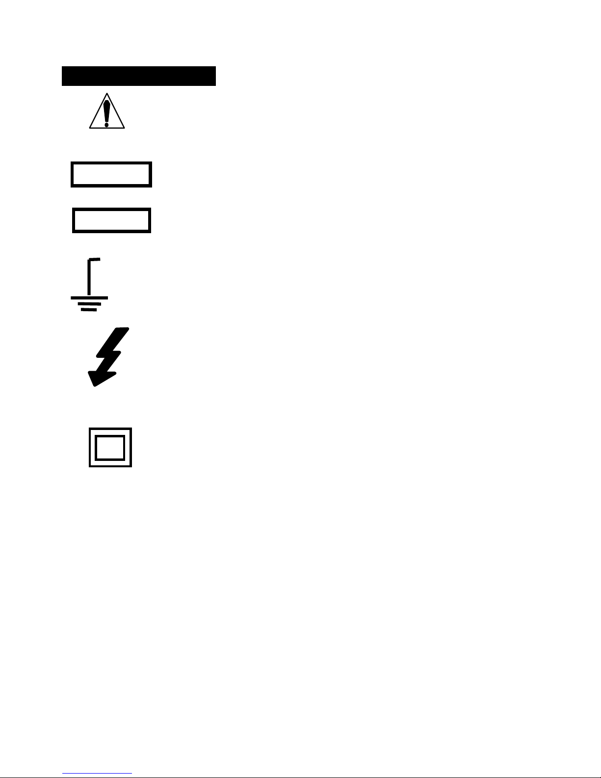
SAF E T Y SYMBOLS
This sy m bo l ad jac e nt to an ot her symb ol ,
terminal or operating device indicates that the
operator must refer to an explanation in the
Oper ati ng Instruc t i ons to av o id per sonal in jur y
or damage to the meter.
WARNING
CAUTION
MAX
600V
This WARNING sy mbol indic a tes a pot en t ia lly
hazardous situation, which if not avoided,
could result in death or serious injury.
This CAUTION sym b ol in dic a tes a potentia lly
hazardous situation, which if not avoided, may
result damage to the product.
This symbol advises the user that the
terminal(s) so marked must not be connected
to a circuit point at which the voltage with
respect to earth ground exceeds (in this case)
600 VAC or VDC.
This sy m bo l ad jac e nt to on e or more ter mi na ls
identifies th em as being associated with
ranges that may, in normal use, be subjected
to particularly hazardous voltages. For
maximum sa fety, the meter and its test leads
shou ld n ot be ha n dled when t h es e termina ls
are energize d.
This symbol indicates that a device is
protected throughout by double insulation or
reinforced insul ati on .
5
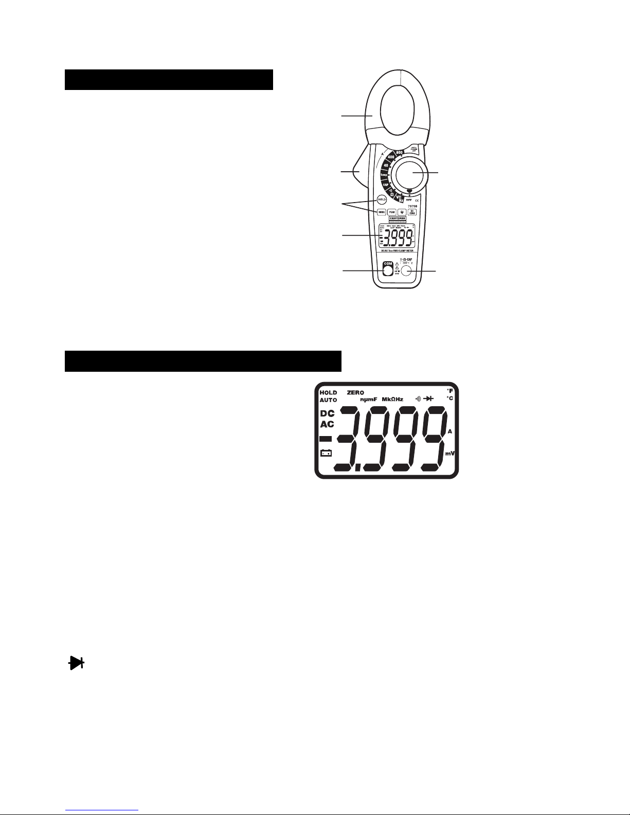
CONTROLS AND JACKS
1. Current clamp
1
2. Clamp opening trigger
3. Control buttons:
• Data Hold
2
6
• Mode
• Peak
3
• Backlight
• DCA Zero
4
4. Backlit LCD Display
5
7
5. COM negative input jack for black test lead
6. Rotary function switch
7. V••CAP•TEMP•HZ• positive input jack for red lead
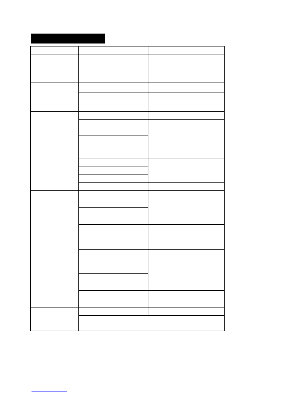
SYMBOLS AND ANNUNCIATORS
HOLD Data Hold
Minus Sign Negative reading displa y
0 to 3999 Measurement display digits
DC ZERO DCA Zero
P
MAX PMIN Peak capture
AUTO Auto Range mode
DC/AC Direct Current/Alternating Current
BAT Low battery
mV or V Milli-volts or Volts (Voltage)
Ohms (Resistance)
A Amperes (Current)
F Farad (Capacitance)
Hz Hertz (Frequency)
o
F and oC Fah r e nh eit and Cels ius units (Tem perature)
n,m,µ,M,k Unit of measure prefixes: nano,milli,micro,mega,& kilo
MIN
P
MAX
P
•))) Continuity
Diode t es t
6
SPECIFICATIONS
Function Range Resolution Accuracy
DC Current
(A DC)
40.00A 0.01A
400.0A 0.1A
± (5% + 10d)
± (5% + 10d)
AC Current
(A AC)
50/60Hz
DC Voltage
(V DC)
AC Voltage
(V AC)
Resistance
Capacitance
800A 1A
40.00A 0.01A
400.0A 0.1A
800A 1A
± (2.8% + 10d)
± (5% + 10d)
± (5% + 10d)
± (2.8% + 10d)
400.0mV 0. 1mV ± (0.8% + 10 digits)
4.000V 1mV
40.00V 10mV
± (1.5% + 2 digits)
400.0V 0.1V
600V 1V ± (2.0% + 3 digits)
400.0mV 0. 1mV ± (1.0% + 10 digits)
4.000V 1mV
40.00V 10mV
± (1.5% + 5 digits)
400.0V 0.1V
600V 1V ± (2.0% + 5 digits)
400.0 0.1 ± (1.0% + 4 digits)
4.000k 1
40.00k 10
± (1.5% + 2 digits)
400.0k 0.1k
4.000M 1k ± (2.5% + 3 digits)
40.00M
10k ± (3.5% + 5 digits)
4.000nF 1pF ± (5.0% + 30 digits)
40.00nF 10pF ± (5.0% + 20 digits)
400.0nF 0.1nF
4.000µF 1nF
± (3.0% + 5 digits)
40.00µF 10nF
400.0µF 0.1µF ± (4.0% + 10 digits)
4.000mF 1µF ± (10% + 10 digits)
40,00mF
4.000kHz
Sensitivity: 100V (<50Hz); 50V (50 to 400Hz);
5V (401 to 4000Hz)
10µF unspecified
1Hz ± (1.5% + 2 digits) Frequency
7
 Loading...