

Page 1
53" W x 24.6" D STAINLESS STEEL CHEST AND CABINET
Model:
714.58647
714.58688
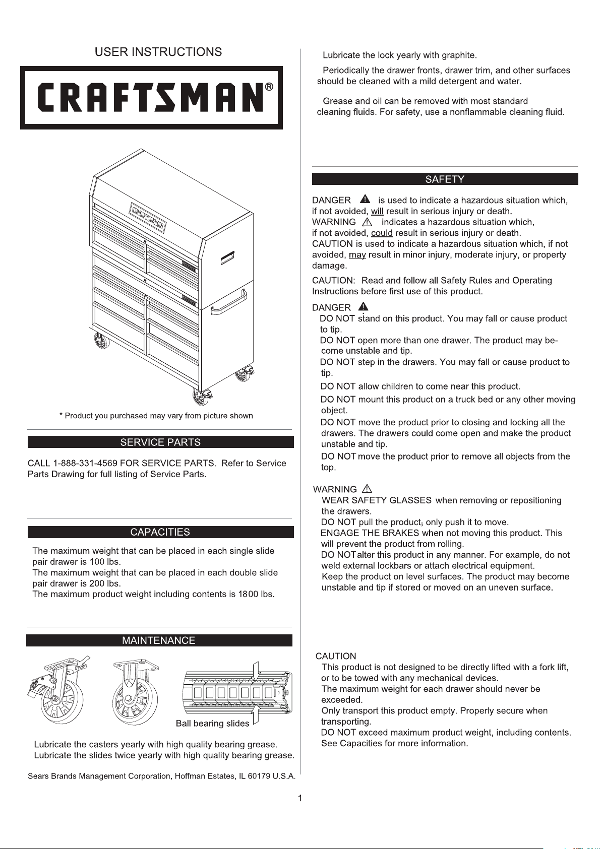
•
•
•
•
•
•
•
•
•
•
•
•
•
•
•
• BE CAREFUL
when closing the lid. Remove hands before
th e lid closes completely.
Used under license.
•
•
•
•
Page 2
from the date of sale this product is
warranted against defects in material or workmanship.
HARDWARE
10mm Wrench
14mm Wrench
CASTER INSTALLATION
Items Needed:
M8 x 20 Hex Bolt (Qty: 16)
Washer 16)
14mm Wrench
This procedure may require the help of an assistant.
Take out casters from the bottom left drawer. •
• Lay cardboard from shipping box on floor. Lay the
cabinet down on its back on the cardboard to protect
paint finish.
• Attach a swivel caster to each bottom corner of the
workstation cabinet using (4) M8 x 20 Hex Bolts and (4)
washers per caster.
• Wrench tighten all screws.
• Return the cart to its upright position.
M6 x 12 Hex Bolt
)
4
M8 x 20 Hex Bolt
16)
Washers
16)
Connection Brackets
(Qty: 2)
M6 x 12 Hex Bolt
(Qty: )
2
NOTE
Not all assembly instructions will relate to your model.
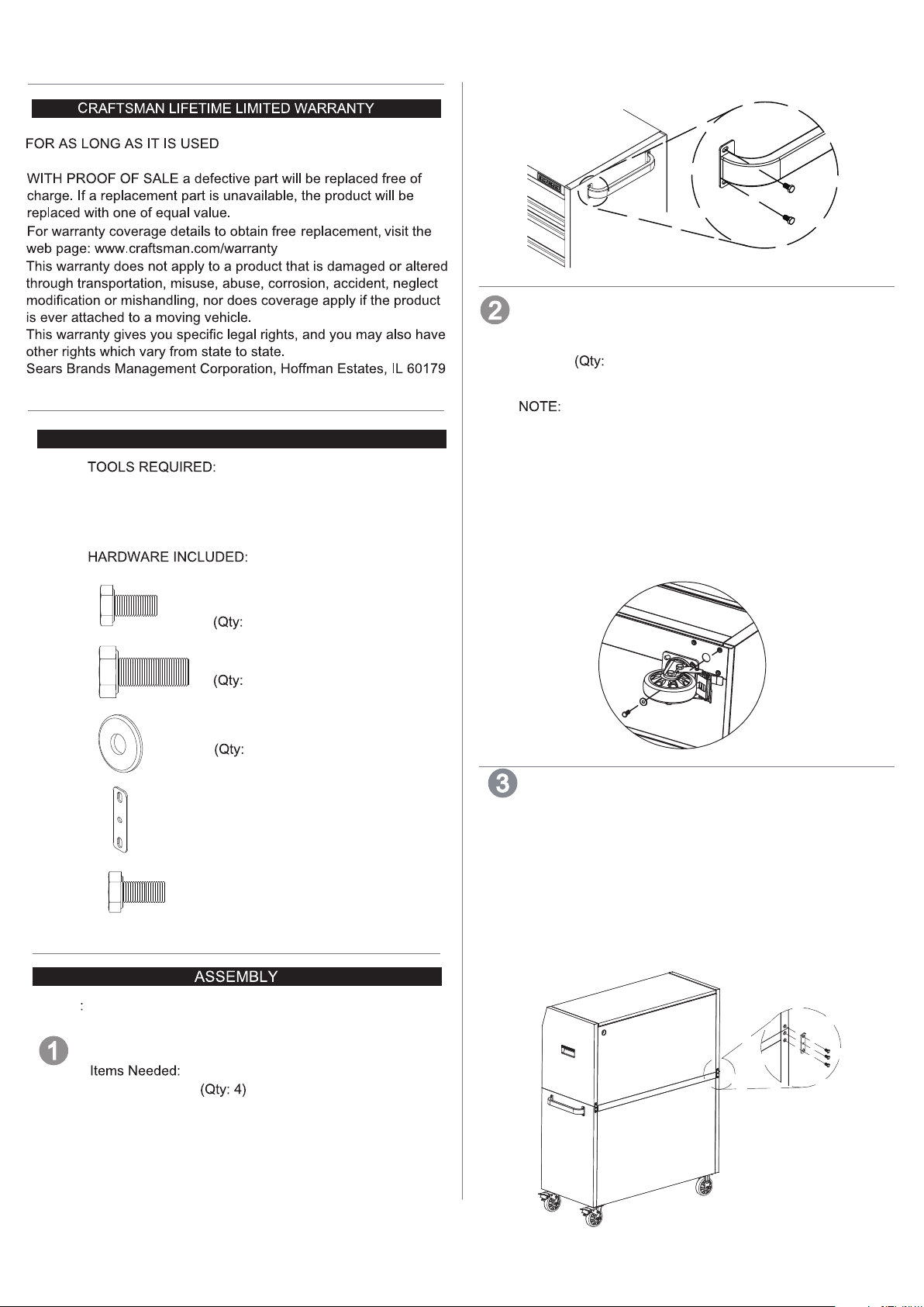
SIDE HANDLE ATTACHMENT
CHEST AND CABINET CONNECTION
•
Remove all drawers from the chest before placing the
chest on the top of the cabinet.
Place the chest on the cabinet. Connect the chest and
•
cabinet together with the connection brackets. Insert the
bracket hook into the slot in the chest. Use the bolt to
secure the bracket to the cabinet as shown.
M6 x 12 Hex Bolt (Qty: 2)
Connection Brackets (Qty: 2)
10mm Wrench
M6 x 12 Hex Bolt
10mm Wrench
• Position the handle over the holes and
with the bolts provided. Tighten securely only
by hand. Do not overtighten.
attach
2
Page 3

Power Strip Cord (Chest)
4
Open the lid and cut the band attaching the cord to the
pegboard.
Draw the cord and plug through the hole in the back of
the chest as shown.
Power Strip Cord (Cabinet)
Cut the black strip holding the cord, then pull the white
strip to get the plug out of the cabinet and through the
grommet. Tighten the grommet.
FCC INSTRUCTION
•
NOTE: This equipment has been tested and found to comply
with the limits for a Class B digital device, pursuant to Part
15 of the FCC Rules. These limits are designed to provide
reasonable protection against harmful interference in a
residential installation. This equipment generates, uses and
can radiate radio frequency energy and, if not installed and
used in accordance with the instructions, may cause harmful
interference to radio communications. However, there is no
guarantee that interference will not occur in a particular
installation. If this equipment does cause harmful interference
to radio or television reception, which can be determined by
turning the equipment off and on, the user is encouraged to
try to correct the interference by one or more of the following
measures:
- Reorient or relocate the receiving antenna.
- Increase the separation between the equipment and receiver.
- Connect the equipment into an outlet on a circuit different
from that to which the receiver is connected.
- Consult the dealer or an experienced radio/ TV technician
for help.
OPERATION
REMOVING DRAWERS
Black
White
•
POWER STRIP SPECIFICATIONS.
MODEL: LTS-04C
SURGE PROTECTIVE DEVICES
RATING: 15A 125VAC 60Hz 1875W
USB:TOTAL 2.1A
USB O/P: IT EQUIPMENT ONLY
VPR:700V (L-N) TYPE 3 SPD
CONFORMS TO UL STD. NO. 1363 AND ANSI/UL STD.
NO. 1449
CERTIFIED TO CSA STD. C22.2 NO. 308 & 8
WARNING: RISK OF ELECTRIC SHOCK.
To avoid serious injury from electric shock:
- Only use the power strip of this product indoors.
- Only use the power strip of this product in a dry location.
- Do not plug another power strip into one of the power
strips of this product.
- Do not plug one of the power strips of this product into
another power strip.
Pull drawer out so that it is almost fully extended.
on one release lever while pulling down on the other release
lever. Pull the drawer outward until it releases from the
drawer slide.
PUSH UP
ONE RELEASE LEVER
INSTALLING DRAWERS
Extend the drawer slides from the tool chest/cabinet.
Insert the brackets on each side of the drawer into
the slots in the chest/cabinet slides, being careful that
they are properly positioned. Once properly inserted,
completely close the drawer to set the slides in their
proper positions.
Extend the Slide
Slide
Bracket
PUSH DOWN
OTHER RELEASE LEVER
Push up
WARNING: Changes or modifications to this unit not expressly
approved by the party responsible for compliance could void
the user's authority to operate the equipment.
3
Page 4

53-In Stainless Steel Chest - Model 714.58647
53-In Stainless Steel Cabinet - Model 714.58688
xx x
The keys are taped to the last
left drawer of the chest.
Ref# Part# Qty
1
2
3
4
5
6
7
8
9
10
Description
Gas Strut
Power Strip
Grommet
Chest Handle
M6 x 12 Hex Bolt
Connection Bracket
Slide (R)
Slide (L)
Lock
Till Liner
303200
333059
314027
306146
321051
222794
300378
300377
304224
552075
2 pcs
1 pc
2 pcs
2 pcs
6 pcs
2 pcs
6 pcs
6 pcs
1 pc
1 pc
xx x
The keys are taped to the top of the caster
carton which is placed in the left bottom
drawer of the cabinet.
Ref# Part# Qty
1
2
3
4
5
6
7
8
9
10
11
12
Description
Cabinet Handle
M6x12 Hex Bolt
Slide (R)
Swivel Caster
Washer
M8x20 Hex Bolt
Rigid Caster
Top Liner
Slide (L)
Lock
Power Strip
Grommet
306142
321051
300378
302214
324002
321024
302215
552076
300377
304224
333059
314027
1 pc
4 pcs
12 pcs
2 pcs
16 pcs
16 pcs
2 pcs
1 pc
12 pcs
1 pc
1 pc
1 pc
10
12
11
10
9
1
8
1
2
3
7
2
4
8
9
5
6
3
7
4
5
6
4
Page 5

To order replacement parts
or schedule repair service
Para ordenar piezas
o pedir servicio de reparación
1-888-331-4569
5
Page 6

INSTRUCCIONES PARA EL USUARIO
53" W x 24.6" D GABINETE CHICO Y GRANDE
DE ACERO INOXIDABLE
Modelo:
714.58647
714.58688
Pr
oducto que ha comprado puede variar de la imagen mostrada
*
PARTES DE SERVICIO
LLAME 1-888-331-4569 para Partes de servicio. Consulte
el dibujo para el listado completo de piezas de servicio.
CAPACIDADES
chico son 100 libras.
grande son 200 libras.
es 1800 libras.
MANTENIMIENTO
Lubrique el candado anualmente con grafito.
de ajuste, y otras
superficiesdeben ser limpiados con detergente y agua.
incombustible.
SEGURIDAD
PELIGRO
si no se evita, puede provocar lesiones graves o la muerte.
ADVERTENCIA
si no se se evita, puede provocar lesiones leves, lesiones
moderadas o propiedad
Instrucciones de funcionamiento antes del primer uso de este
producto
PELIGRO
No se pare sobre este producto. Usted puede caerse o
hacer que el producto se caiga boca bajo.
puede ser inestable y caerse.
NO se pare en los cajones. Usted puede caerse o haga que el
producto se caiga boca bajo.
NO mueva el producto antes de cerrar y bloquear todos los
cajones. Los
NO mueva el producto antes de quitar todos los objetos de la
parte superior.
ADVERTENCIA
.
ENGAGAR LOS FRENOS
el gabinete. Esto previene que el producto se mueva.
NO altere este producto de cualquier manera. Por ejemplo,
no suelde
Mantenga el producto en superficies planas. El producto
puede estar inst able y la unidad puede caerse boca abajo si
Tenga cuidado al cerrar la tapa. Retire las manos antes de
cerrar La tapa completamente.
.
r una si
ca
cuando se encuentre estacionado
.
Lubricar las ruedas anualmente con grasa de alta calidad.
Cojinetes de
Lubricar los diapositivas del
de alta calidad.
ears Brands Management Corporation, Hoffman Estates, IL 60179 U.S.A.
S
Used under license.
Bolas
PRECAUC
directamente con un montacargas o para ser
excedido.
Asegura
adecuadamente cuando transporte.
maxim o peso d el pro duct o, inc luye ndo el
vac o.
conte nido . Lea la s capa cida des pa ra obtener mas
6
Page 7

GARANT A LIMITADA DE CRAFTSMAN LIFETIME
DURANTE EL TIEMPO QUE SE UTILICE desde la fecha de venta,
este producto est garantizado contra defestos de material or mano
de obra.
CON PRUEBA DE VENTA una pieza defectuosa ser reemplazada
gratuitamente. Si una pieza de repuesto no est disponible,el producto
ser
reemplazado por uno de igual valor.
web: www.craftsman.com/warranty
ado o alterado por
movimiento.
Sears Brands Management Corporation, Hoffman Estates, IL 6017 9
HERRAMIENTAS
10mm Llave
14mm Llave
EQUIPOS
NECESARIAS:
INSTALACION DE LAS RUEDAS
Necesarios:
Arandelas (CANT: 16)
g
M8 x 20 Perno H
10mm Llave
NOTA: Este procedimiento puede requerir la ayuda de un asistente.
exa
onal (CANT: 16)
Saque las ruedas del cajon de abajo, a la izquierda.
Coloque el gabinete hacia abajo sobre su espalda
Sujete una ruedecilla giratoria a cada esquina inferior
hexagonales M8 x 20 y (4) arandelas por lanzador.
Apriete todos los tornillos con llave.
Devuelva el carro a su posiscion vertical.
HERRAMIENTA INCLUIDO:
M
Hexagonal (CANT: 4)
M8 x 20 Perno
Hexagonal (CANT: 16)
Arandelas
(CANT: 16)
Conexion de
Soporte (CANT: 2)
M6 x 12 Perno
Hexagonal (CANT: 2)
ASAMBLEA
NOTA: No todas las
con su modelo.
LATERAL MANGO ACCESORIO
A
M6 x 12 Perno H
10mm Llave
Ponga la manilla sobre los huecos y
con los pernos provistos. Apriete firmemente
solamente con su mano No apriete en exceso. .
Necesarios:
exagonal (CANT: 4)
6 x
12 Perno
engan
char
GABINETE CHICO Y GRANDE CONEXION
Retire todos los cajones del pecho antes de colocar
el pecho en la parte superior del gabinete.
Ponga el gabinete chico arriba del gabinete grande.
Conectar el gabinete chico y el gabinete grande junto
con los soportes de conexión. Utilicé tres tornillos para
cada soporte como se muestran.
M6 x 12 Perno Hexagonal (CANT: 2)
Conexion de Soporte (CANT: 2)
mm
10
Llave
7
Page 8

CABLE ELECTRICO (GABINETE CHICO)
4
Abra la tapa y cortar la banda de fijar el cable a la
lámina de cartón.
Empuje el cable y el enchufe a través del agujero en la
CABLE ELECTRICO (GABINETE GRANDE)
Corte la tira negra que sujeta el cable, luego tire de la tira
blanca para sacar el enchufe del gabinete y por la arandela.
Aprieta la arandela.
Black
Instrucción FCC
NOTA: Este equipo ha sido probado y cumple con los límites
para un dispositivo digital de Clase B, según la Parte 15 de
las normas de la FCC. Estos límites están diseñados para
proporcionar una protección razonable frente a interferencias
perjudiciales en una instalación residencial. Este equipo
genera, utiliza y puede irradiar energía de radiofrecuencia y,
si no se instala y utiliza de acuerdo con las instrucciones,
puede causar interferencias en las comunicaciones de radio.
Sin embargo, no hay garantía de que no se produzcan
interferencias en una instalación particular. Si este equipo
causa interferencias perjudiciales en la recepción de radio o
televisión, lo cual puede determinarse apagándolo y
encendiéndolo, se recomienda al usuario que intente corregir
la interferencia mediante una o más de las siguientes medidas:
- Reorientar o reubicar la antena receptora.
- Aumente la separación entre el equipo y el receptor.
- Conectar el equipo a una toma de un circuito distinto de
aquel al que est conectado el receptor .á
- Consulte al distribuidor oa un técnico de radio / TV
para
obtener ayuda .
OPERACION
REMOVIENDO CAJONES
completamente
White
ESPECIFICACIONES DE LOS CABLES
ELÉCTRICOS
MODELO: LTS-04C
SURGE DISPOSITIVO DE PROTECCIÓN
CLASIFICACIÓN: 15A 125VAC 60Hz 1875W
USB: TOTAL 2.1A
USB O/P: "TI" SOLO EQUIPO
VPR: 700V (L-N) TIPO 3 SPD
AJUSTARSE A UL STD. n.o 1363 Y ANSI/UL STD. n.o 1449
CERTIFICADO CSA STD. C22 2 n.o 308 & 8
ADVERTENCIA
Para evitar lesiones graves por descarga eléctrica:
: RIESGO DE DESCARGA ELÉCTRICA.
- Utilice únicamente la regleta de este producto en interiores.
- Utilice únicamente la regleta de alimentación de este
producto en un lugar seco.
- No enchufe otra regleta en una de las bandas de
alimentación de este producto.
- No enchufe una de las bandas de alimentación de este
producto en otra regleta.
.
EMPUJE PARA ARRIBA
PALANCA DE LIBERACIÓN
EMPUJE PARA ABAJO
LA OTRA
PALANCA DE LIBERACIÓN
INSTALACION DE LOS CAJONES
Extender las diapositivas del gabinete grande.
ranuras de las diapositivas en el los dos gabinetes,
posicionados. Ya insertado correctamente, cierre
en su posiciones adecuadas.
Extender la Di
apositiva
Diapositiva
Soporte
ADVERTENCIA: Los cambios o modificaciones a esta unidad
no aprobados expresamente por la parte responsable del
cumplimiento podrían anular la autoridad del usuario para
operar el equipo.
8
Page 9

Cofre D e Ac ero In oxid able D e 53 Pul g - Modelo 714.58647 Gabin ete De Ace ro Ino xida ble De 5 3 Pulg - Modelo 714 .586 88
Ref#
1
2
3
4
5
6
7
8
9
10
xx x
Muella de Gas
Cable Electrico
Ojal
Manija del Gabinete
M6 x 12 Perno Hex
Conexion de Soporte
Diapositivas (D)
Diapositivas (I)
Candado
Forro de Cajon
Parte# CANT
303200
333059
314027
306146
321051
222794
300378
300377
304224
552075
2 pcs
1 pc
2 pcs
2 pcs
6 pcs
2 pcs
6 pcs
6 pcs
1 pc
1 pc
1
2
3
4
5
6
7
8
9
10
11
12
Ref#
xx x
coloca en el cajon izquierda de abajo.
Mango de Gabinete
M6 x 12 perno hex
Diapositivas (D)
Ruedas Giratorias
Arandelas
M8 x 20 perno hex
Rueda
Forro de Cajon
Diapositivas (I)
Candado
Cable Electrico
Ojal
Parte# CANT
306142
321051
300378
302214
324002
321024
302215
552076
300377
304224
333059
314027
1 pc
4 pcs
12 pcs
2 pcs
16 pcs
16 pcs
2 pcs
1 pc
12 pcs
1 pc
1 pc
1 pc
10
12
11
10
9
1
8
1
2
3
7
2
4
8
9
5
6
3
7
4
5
6
Page 10

To order replacement parts
or schedule repair service
Para ordenar piezas
o pedir servicio de reparación
1-888-331-4569
10
 Loading...