

Craftsman 714.58688, 714.58647 User Instructions
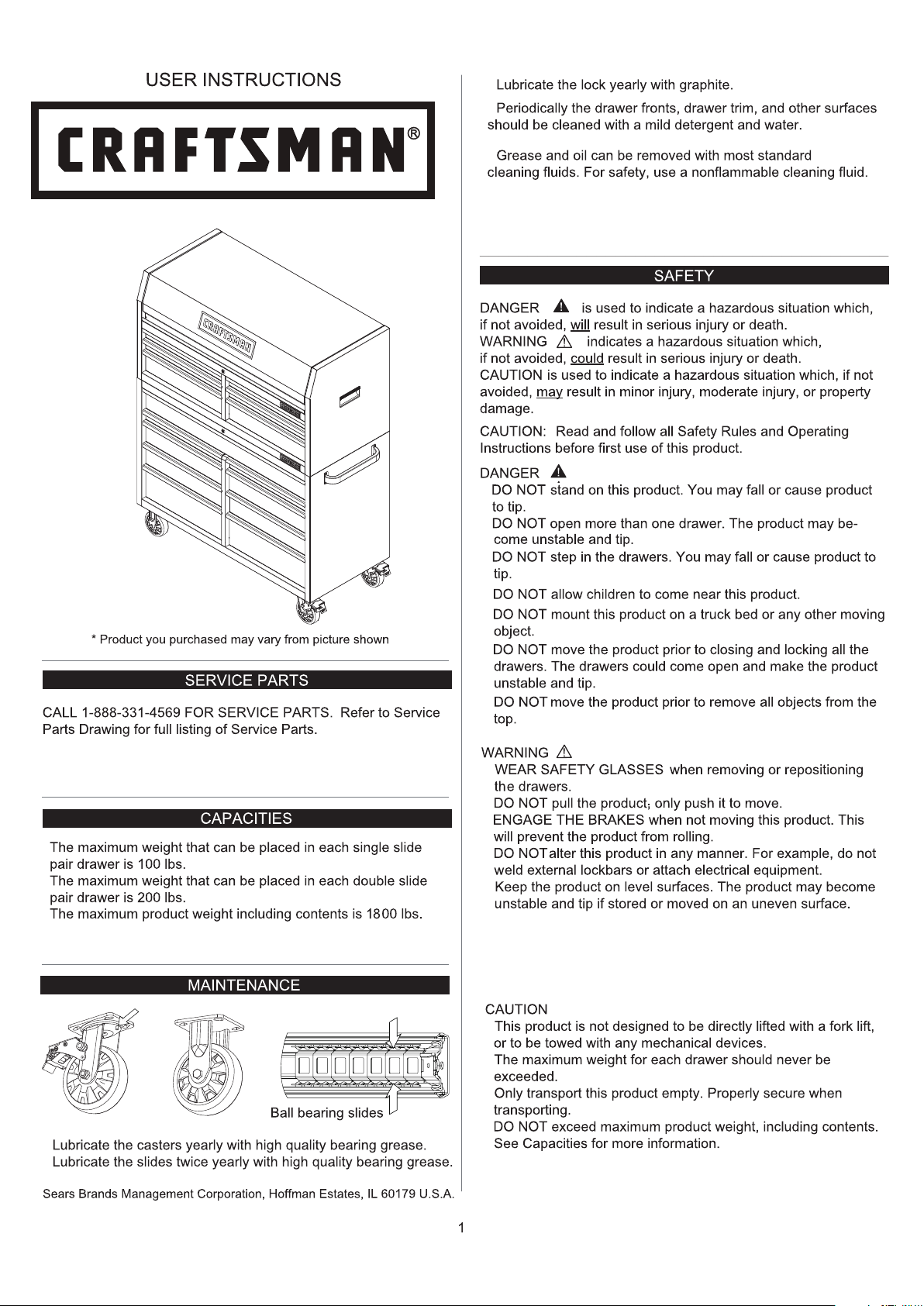
53" W x 24.6" D STAINLESS STEEL CHEST AND CABINET
Model:
714.58647
714.58688
•
•
•
•
•
•
•
•
•
•
•
•
•
•
•
• BE CAREFUL
when closing the lid. Remove hands before
th e lid closes completely.
Used under license.
•
•
•
•
from the date of sale this product is
warranted against defects in material or workmanship.
HARDWARE
10mm Wrench
14mm Wrench
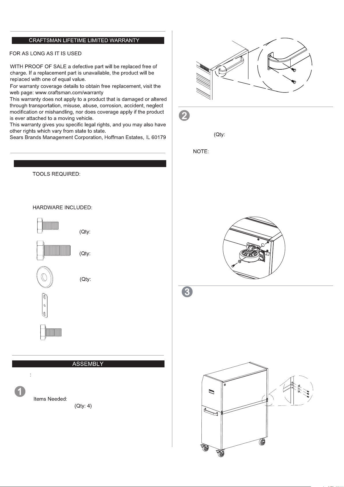
CASTER INSTALLATION
Items Needed:
M8 x 20 Hex Bolt (Qty: 16)
Washer 16)
14mm Wrench
This procedure may require the help of an assistant.
Take out casters from the bottom left drawer. •
• Lay cardboard from shipping box on floor. Lay the
cabinet down on its back on the cardboard to protect
paint finish.
• Attach a swivel caster to each bottom corner of the
workstation cabinet using (4) M8 x 20 Hex Bolts and (4)
washers per caster.
• Wrench tighten all screws.
• Return the cart to its upright position.
M6 x 12 Hex Bolt
)
4
M8 x 20 Hex Bolt
16)
Washers
16)
Connection Brackets
(Qty: 2)
M6 x 12 Hex Bolt
(Qty: )
2
NOTE
Not all assembly instructions will relate to your model.
SIDE HANDLE ATTACHMENT
CHEST AND CABINET CONNECTION
•
Remove all drawers from the chest before placing the
chest on the top of the cabinet.
Place the chest on the cabinet. Connect the chest and
•
cabinet together with the connection brackets. Insert the
bracket hook into the slot in the chest. Use the bolt to
secure the bracket to the cabinet as shown.
M6 x 12 Hex Bolt (Qty: 2)
Connection Brackets (Qty: 2)
10mm Wrench
M6 x 12 Hex Bolt
10mm Wrench
• Position the handle over the holes and
with the bolts provided. Tighten securely only
by hand. Do not overtighten.
attach
2

Power Strip Cord (Chest)
4
Open the lid and cut the band attaching the cord to the
pegboard.
Draw the cord and plug through the hole in the back of
the chest as shown.
Power Strip Cord (Cabinet)
Cut the black strip holding the cord, then pull the white
strip to get the plug out of the cabinet and through the
grommet. Tighten the grommet.
FCC INSTRUCTION
•
NOTE: This equipment has been tested and found to comply
with the limits for a Class B digital device, pursuant to Part
15 of the FCC Rules. These limits are designed to provide
reasonable protection against harmful interference in a
residential installation. This equipment generates, uses and
can radiate radio frequency energy and, if not installed and
used in accordance with the instructions, may cause harmful
interference to radio communications. However, there is no
guarantee that interference will not occur in a particular
installation. If this equipment does cause harmful interference
to radio or television reception, which can be determined by
turning the equipment off and on, the user is encouraged to
try to correct the interference by one or more of the following
measures:
- Reorient or relocate the receiving antenna.
- Increase the separation between the equipment and receiver.
- Connect the equipment into an outlet on a circuit different
from that to which the receiver is connected.
- Consult the dealer or an experienced radio/ TV technician
for help.
OPERATION
REMOVING DRAWERS
Black
White
•
POWER STRIP SPECIFICATIONS.
MODEL: LTS-04C
SURGE PROTECTIVE DEVICES
RATING: 15A 125VAC 60Hz 1875W
USB:TOTAL 2.1A
USB O/P: IT EQUIPMENT ONLY
VPR:700V (L-N) TYPE 3 SPD
CONFORMS TO UL STD. NO. 1363 AND ANSI/UL STD.
NO. 1449
CERTIFIED TO CSA STD. C22.2 NO. 308 & 8
WARNING: RISK OF ELECTRIC SHOCK.
To avoid serious injury from electric shock:
- Only use the power strip of this product indoors.
- Only use the power strip of this product in a dry location.
- Do not plug another power strip into one of the power
strips of this product.
- Do not plug one of the power strips of this product into
another power strip.
Pull drawer out so that it is almost fully extended.
on one release lever while pulling down on the other release
lever. Pull the drawer outward until it releases from the
drawer slide.
PUSH UP
ONE RELEASE LEVER
INSTALLING DRAWERS
Extend the drawer slides from the tool chest/cabinet.
Insert the brackets on each side of the drawer into
the slots in the chest/cabinet slides, being careful that
they are properly positioned. Once properly inserted,
completely close the drawer to set the slides in their
proper positions.
Extend the Slide
Slide
Bracket
PUSH DOWN
OTHER RELEASE LEVER
Push up
WARNING: Changes or modifications to this unit not expressly
approved by the party responsible for compliance could void
the user's authority to operate the equipment.
3
 Loading...