

Craftsman 706149050 Owner’s Manual
F1720
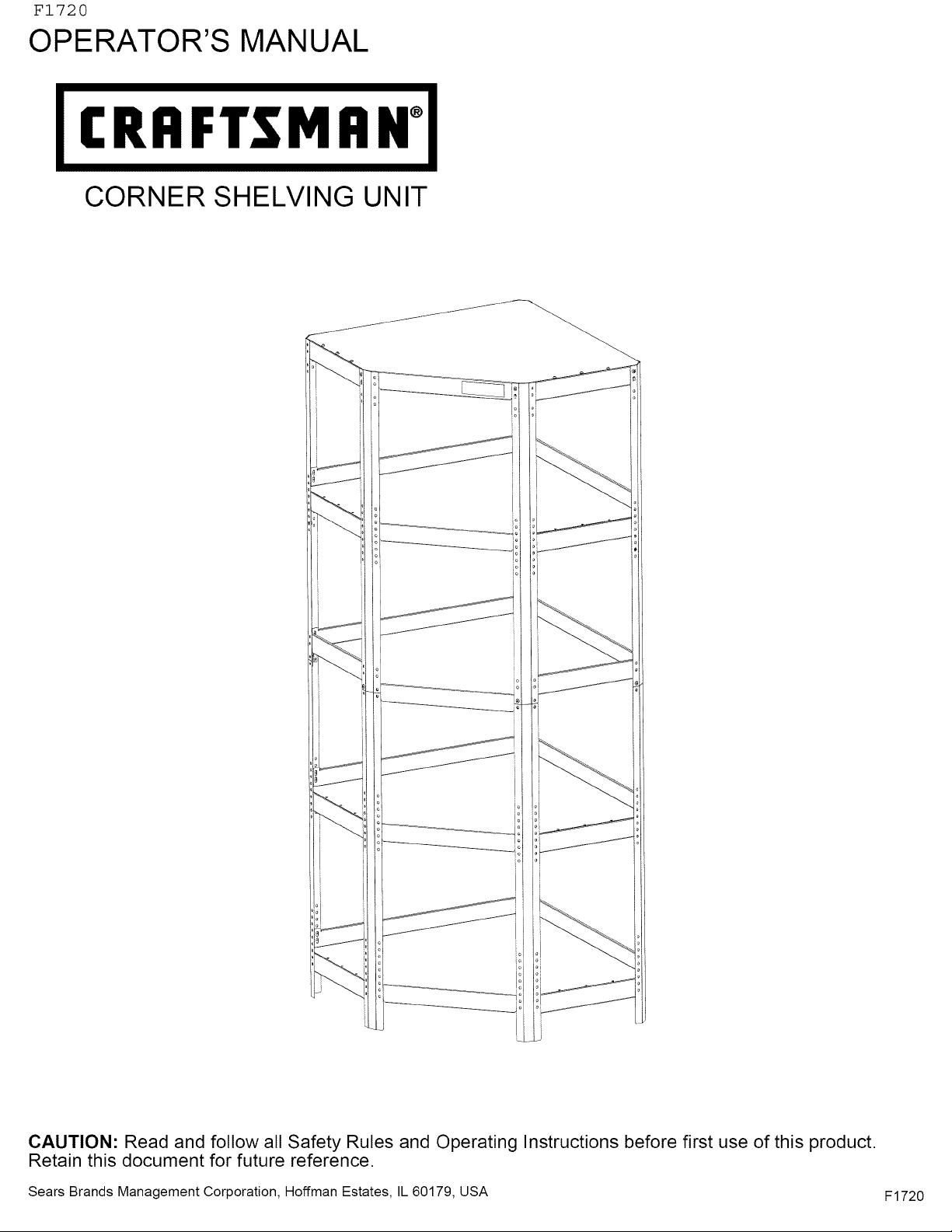
OPERATOR'S MANUAL
I €RAFTSM AH°l
CORNER SHELVING UNIT
CAUTION: Read and follow all Safety Rules and Operating Instructions before first use of this product.
Retain this document for future reference.
Sears Brands Management Corporation, Hoffman Estates, IL 60179, USA F1720
SAFETY WARNINGS AND CAUTIONS:
• Use appropriate safety equipment when using power and hand tools. Failure to do so may cause personal injury i
or product damage. |
• Use adequate manpower when assembling and moving this unit. Failure to do so may cause personal injury or |
product damage. |
• DO NOT stand on this product. You may fall which may cause personal injury. |
• DO NOT mount this product on a truck bed or any other moving object. This may cause personal injury or |
product damage. |
• Appropriately secure this product before moving it with a forklift. |
• DO NOT alter this product in any manner. For example, do not weld external Iockbars or attach electrical |
equipment. This may cause product damage or personal injury. |
• Keep the product on level surfaces. The product may become unstable and tip if stored or moved on an un-level i
surface, which may cause personal injury or product damage. |
• Maximum combined weight limit not to exceed 5,000 pounds (Max. of 1,000 pounds per shelf, evenly |
distributed). If the limit is exceeded, the product could collapse and cause personal injury or product damage. J
k.
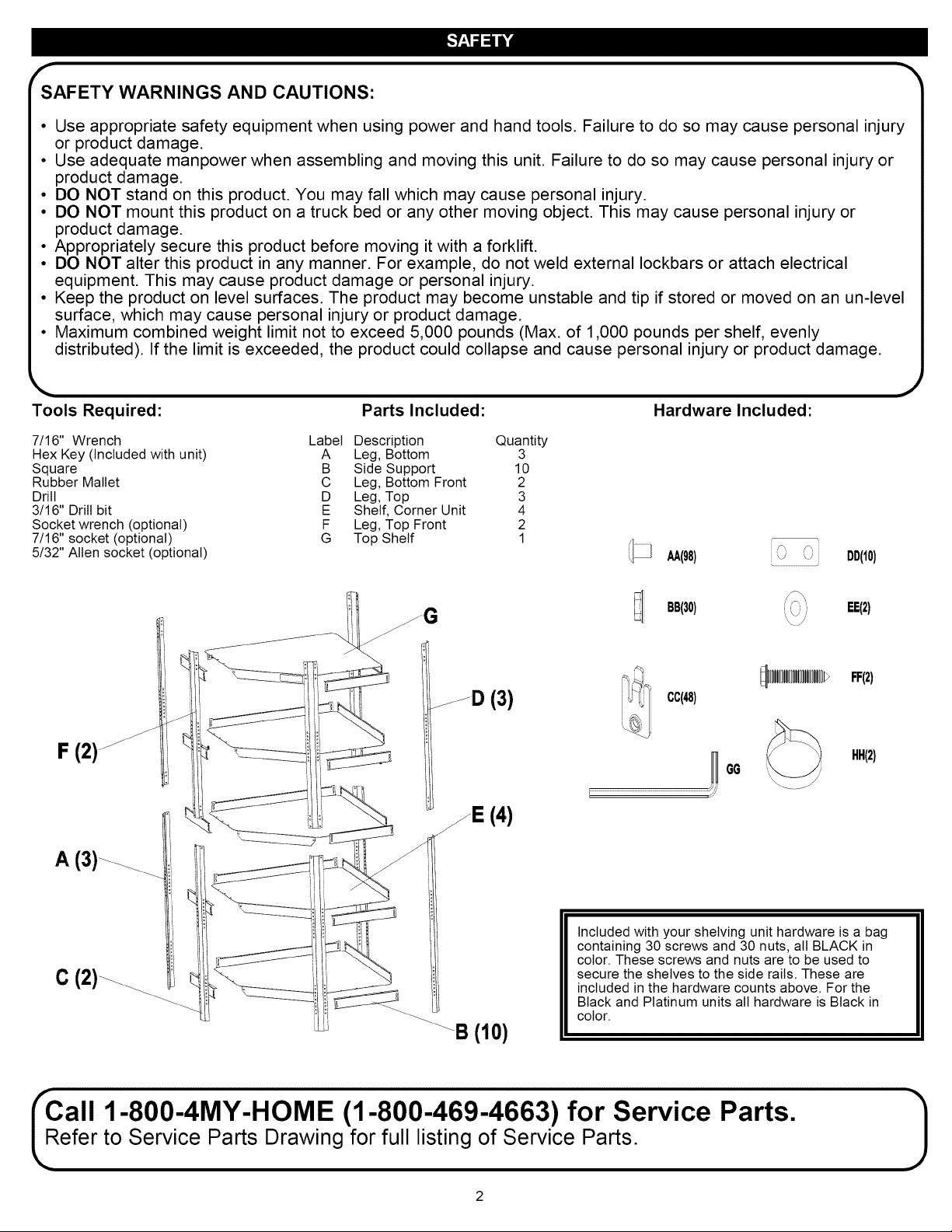
Tools Required: Parts Included: Hardware Included:
7/16" Wrench Label Description Quantity
Hex Key (Included with unit) A Leg, Bottom 3
Square B Side Support 10
Rubber Mallet C Leg, Bottom Front 2
Drill D Leg, Top 3
3/16" Drill bit E Shelf, Corner Unit 4
Socket wrench (optional) F Leg, Top Front 2
7/16" socket (optional) G Top Shelf 1
5/32" Allen socket (optional)
AA(98) DD(10)
J
F (2)
A (3)_
C (2)_
_D (3)
!E (4)
BB(30) _ EE(2)
FF(2)
cc(48)
HH(2)
H GG
r
Included with your shelving unit hardware is a bag
containing 30 screws and 30 nuts, all BLACK in
color. These screws and nuts are to be used to
secure the shelves to the side rails. These are
included in the hardware counts above. For the
Black and Platinum units all hardware is Black in
color.
Call 1-800-4MY-HOME (1-800-469-4663) for Service Parts.
efer to Service Parts Drawing for full listing of Service Parts.

r
fTh _'_
is shelving unit was designed to be flexible for the consumer
to assemble in different configurations. The only shelves that
have specific placements are the middle shelf (where the legs
connect) and the top shelf. The other shelves can be varied in
their placement to suit the customer's storage requirements.
NOTE: While unpacking the shelving unit, save the packaging
materials to use as a scratch free surface.
The customer must first decide if they want an "Open" or
"Closed" shelf design. (See examples)
OPEN CLOSED
NOTE: For ease of assembly,finger tighten all fasteners until
instructed to wrench tighten.
The following directions describe how to assemble both
methods. The exact shelf placement is left up to the customer.
STEP (1): Bottom Section
_ AA (32)
cc (20)
BB (12)
NOTE: The lower legs need to be in the correct orientation to
assemble correctly. The end that has NO holes is the bottom,
and the end with one hole is the top.
The support rail MUST always rest underneath the shelf for
proper support.
• For an "open" shelf, place the support
even with the holes that wilt be used to
mount the front of the shelf. (See
illustration
For a "closed" shelf, mount the bottom
slot in the support bracket (3) holes
higher than the bottom hole in the front
flange of the shelf.
BACK
FRONT
• Starting with the bottom shelf, decide where the shelf wilt be
located. Assemble (1) side support B between (1) of the back
legs A and (1) of the front legs C using (2) QuickLink TM
fasteners CC and (2) Screws AA to create a front leg bottom
assembly.
• Push the QuickLink TM fasteners into the lower mounting slots
(1) on the inside of the support then through the holes on the
legs. Rotate the QuickLink TM fasteners upwards (2) to align
with the upper slots and the holes in the legs. Insert the screws
from the front of the legs (3) and finger tighten. (See illustration
below).
• Tap on the top of the side support with a rubber hammer to
make sure the rail is fully seated at the top of the slot on both
sides.
• Repeat step for the other front leg assembly mirroring the
position of the legs.
BACK
FRONT
k,,.. .j

fSTEP (2): -"
• Lay (1) shelf E on the support of one leg front assembly made
in step 1, and place (1) BLACK screw AA through the center
hole to temporarily hold the shelf in place. Attach (1) BLACK
nut BB and finger tighten. Place the other front leg assembly
with support on the other side of the shelf and secure with (1)
BLACK screw AA and (1) BLACK nut BB.
• Take the last leg A and place it along the back corner of the
shelf and secure with (2) QuickLink TM fasteners CC and (2)
screws AA.
• Place (2) QuickLink TM fasteners CC in the sides of the shelf
securing it to both of the front leg assemblies made in step 1.
Secure with (2) screws AA. Place remaining (4) BLACK screws
in the other holes securing the shelf to the rail with the (4)
BLACK nuts BB.
• Repeat steps 1 & 2 for the second shelf and set this assembly
aside for later use.
STEP (3): TopSection
_u& (32)
cc (20)
_1 BB (12)
NOTE: The upper legs need to be in the correct orientation to
assemble correctly. The end of the leg that has (4) holes is the
top, and the end with (3) holes is the bottom.
STEP (5): Attach Top section to Bottom Section
(34)
BB(6)
r ......................................................................................
f_ S_
\ S \ Y
DD (10)
NOTE: The nut plates DD MUST be used to connect the legs
together at all 8 locations. The QuickLink TM fastener CAN NOT
be used to attach the legs.
• Using the assembly made in steps 1 & 2, attach (6) nut plates
DD to the back legs and secure with (6) screws AA.
• Attach (2) nut plates DD to the front legs on the side of the
leg closest to the back legs and secure with (2) screws AA.
(See illustration below).
BACK
cc(8)
• Assemble (1) side support B between (1) of the back top legs
D and (1) of the top front legs F using (2) QuickLink TM
fasteners CC and (2) Screws AA for the MIDDLE shelf in this
section. Keep in mind the placement of the side supports with
the final location of the shelf.
• Repeat step for the other top front leg assembly mirroring the
position of the legs.
STEP (4):
• Lay (1) shelf E on the support of one leg side assembly made
in step 3, and place (1) BLACK screw _ through the center
hole to temporally hold the shelf in place. Attach (1) BLACK
nut BB and finger tighten. Place the other assembled leg side
assembly with support on the other side of the shelf and
secure with (1) BLACK screw _ and (1) BLACK nut BB.
• Take the last leg D and place it along the back corner of the
shelf and secure with (2) QuickLink TM fasteners CC and (2)
screws AA.
• Place (4) QuickLink TM fasteners CC in the front and sides of
the shelf and secure with (4) screws AA. Place remaining (4)
BLACK screws _ in the other holes securing the shelf to the
rail with the (4) BLACK nuts BB.
• Repeat steps 3 & 4 for the TOP shelf.
NOTE: The top shelf can be assembled so it is flush with the top
of the legs, or it can be set lower to create a closed shelf. The
steps are the same, but the location is different. (See illustrations
below.)
FRONT
• With assistance from a helper, lift the top assembly and place
over the bottom assembly lining up the front and back legs.
• Secure with (10) screws AA.
• Assemble the last shelf C to the unit, being sure to place the
front flange of the shelf between the leg ends and secure with
(4) screws AA and (2) nut plates DD on the front flange.
• Secure the back of the shelf with (4) QuickLink TM fasteners CC
and (4) screws AA.
• Place (1) side support B in either the "open" or "closed" side
position.
• For "CLOSED" position secure with (2) QuickLink TM fasteners
CC and (2) screws AA then repeat for other side.
• Secure the (2) nut plates DD under this side support B with (2)
screws AA.
• For "OPEN" position, you wilt need to remove the screw AA
and nut plate DD from the sides of the unit. Locate the side
support B and then secure the nut plate DD with (2) screws.
For this location, the QuickLink TM fasteners CC are NOT used.
• Secure the sides of the shelf to the side supports with (6)
BLACK screws AA and (6) BLACK nuts BB.
STEP (6): Finaltightening
• Starting with the bottom shelf, use a square to square up the
legs and the shelf and tighten the screws using the hex key
GG.
• Continue with each shelf making sure to square up all (5) legs.
 Loading...