

Page 1
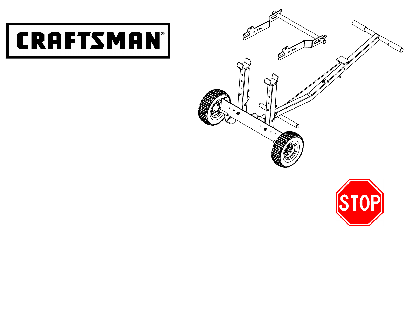
User Instructions
TRACTOR LIFT
Model Number 610.24600
Provides access to mower deck for easy
•
cleaning and service
Fits all 1985 through current models
•
of CRAFTSMAN front engine tractors
and Zero Turn Mowers
Can be fitted to most major front engine tractor brands
•
Patent Pending
Adjustable arms for greater versatility
•
Extra heavy duty gauge steel construction
•
If you read and follow these instructions, this product can be
•
assembled in approximately 20 minutes
Assemble unit on cardboard to avoid scratches or damage to parts
•
Can easily be assembled by one person
•
All fasteners for this Tractor Lift can be purchased at Sears or any
•
hardware store
Sears, Roebuck and Co., Hoffman Estates, IL 60179 U.S.A.
Visit our Craftsman website: www.sears.com/craftsman
If there are any missing
•
parts, or if you have any
questions on assembly,
operation, maintenance
or safety, please call
1-800-652-6231
610.24600-REV B 3/08
Page 2

WARNINGS
Always use the stabilizer bar provided when using tractor lift.
•
Make sure stabilizer bar is properly in place before starting any
work on tractor.
Read and understand all safety and operating instructions
•
before using the tractor lift.
with these instructions to use the tractor lift.
Read and understand all safety and operating instructions
•
provided by the tractor's manufacturer before using tractor lift.
Never
•
•
•
•
•
•
•
•
•
lay under the tractor or mowing deck.
When using lift, keep all bystanders, including children, away.
This tractor lift must be only used for lifting and lowering to
and from a level and stable surface.
Never
use in wet conditions.
Do not
time.
Do not
which it is not intended or designed.
If tractor lift is bowing while lifting or lowering your tractor, which
indicates an overload condition, remove the tractor immediately.
Do not
running.
Never
attempt to lift the front and back of the tractor at the same
use tractor lift as an automotive lift, or for any other use for
attempt to lift or lower any power equipment while motor is
engage blades while using tractor lift.
Never
allow anyone unfamiliar
SAFETY INSTRUCTIONS
Be sure to read and follow all safety instructions and
•
warnings. Failure to follow these instructions may result in
damage to the product and/or serious personal injury.
Danger of serious personal injury exists. Serious personal
•
injury can occur when using a lifting device.
Never
•
•
•
•
•
•
•
•
•
any mild detergent.
•
attempt to ride any vehicle up or down the tractor lift.
Do not climb onto tractor while tractor is in the elevated position.
When working on the front of the tractor always place wheel
chocks in back of the rear wheels/tires.
Always raise and lower tractor lift in a controlled fashion; do not
allow the tractor to drop too quickly, damage could occur.
Make sure lifting arms are aligned and set to the proper distance apart
so that the equipment being loaded is well balanced on the lift.
Do not remove warning decals from product.
Before each use, always check for any worn, loose, or
damaged parts on the tractor lift. If any damage is present,
DO NOT USE THE TRACTOR LIFT
Periodically check the fasteners to make sure they are still
tight and in place.
Keep lift surface clean by occasionally cleaning with water and
Do not add to or try to modify the tractor lift in any way.
Any modifications will void any warranties.
.
Always
•
any work on tractor.
Do not
•
Failure to follow these warnings may result in property
•
damage and/or serious bodily injury.
disconnect spark plug wire from tractor before beginning
exceed the rated capacity of the tractor lift - 270#.
FOR MISSING PARTS, Call 1-800-652-2321, Monday - Friday, 8 a.m. - 5 p.m. E.S.T.
Page 2.
Failure to abide by the warnings and read the safety instructions may
•
result in loss of load, damage to lift and/or property, serious personal
and/or fatal injury.
Page 3
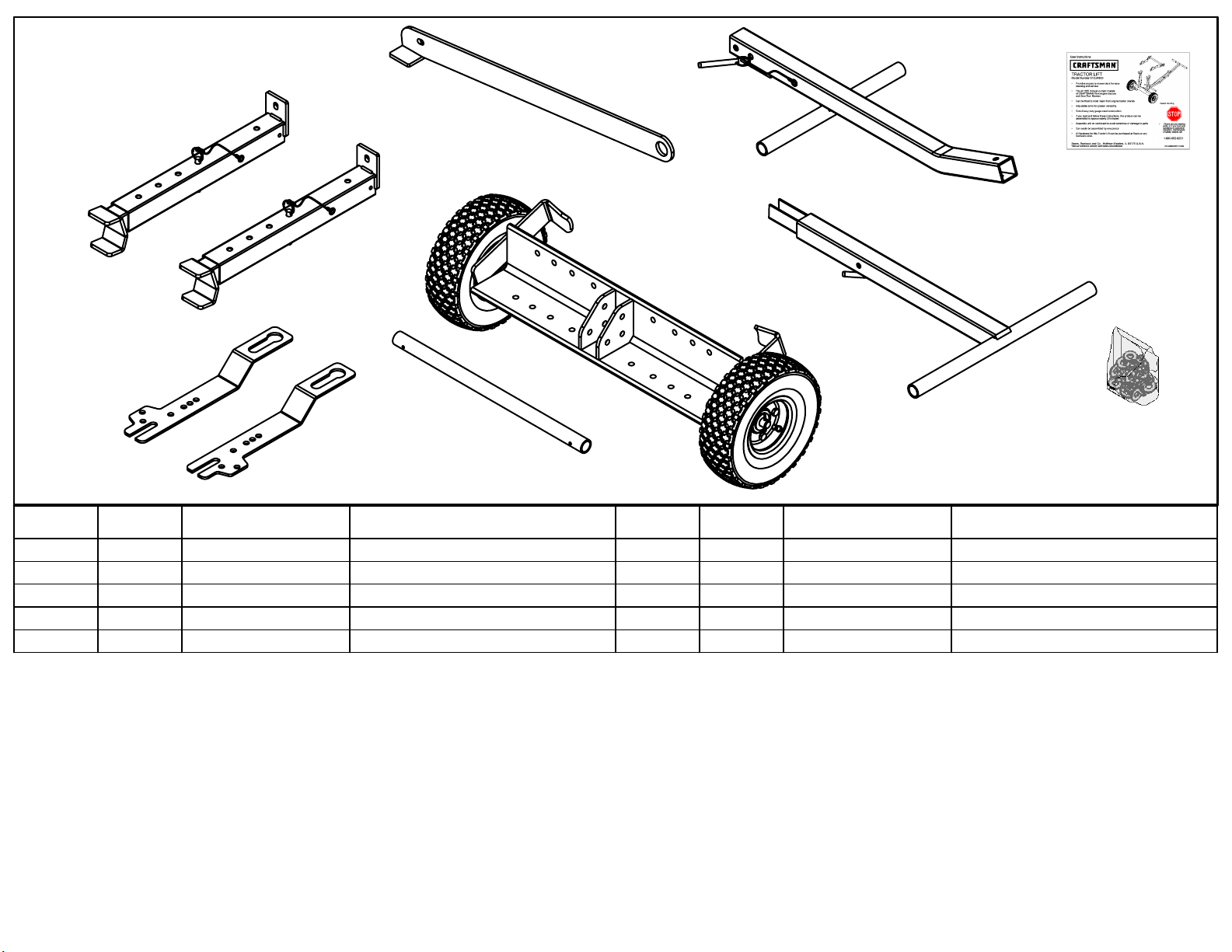
Carton Contents
4
8
3
11
6
7R
REF NO
1 1 51001
2 1 51002
3 1 51003
4 2 41009
6 1 51005
QTY
PART NUMBER
7L
DESCRIPTION
Angle Frame Assembly
Handle Top
Handle Bottom
Lift Tube Assembly
Lift Cross Tube
OPERATION
Tractor Lift can be used out of the box on all Craftsman tractors
with bumpers or brush guards. Tractor Lift mounting hardware is
provided if your tractor does not have a bumper or brush guard.
TOOLS REQUIRED FOR ASSEMBLY
9/16" Wrench and/or Socket
Adjustable wrench
1
REF NO
7L 1 410131
7R
8 1 51006
10 1 310031
11 1 310041
QTY
1 410132
PART NUMBER
MAINTENANCE
Store unit in a clean dry place.
Recommended tire pressure - 30 PSI.
Before each use:
Always check tire pressure.
•
Always inspect unit for damage.
•
Always check fasteners for tightness.
•
2
DESCRIPTION
Tractor Mounting Bar - Left
Tractor Mounting Bar - Right
Stabilizer Bar
Hardware Bag
Assembly Manual
10
FOR MISSING PARTS, Call 1-800-652-2321, Monday - Friday, 8 a.m. - 5 p.m. E.S.T.
Page 3.
Page 4
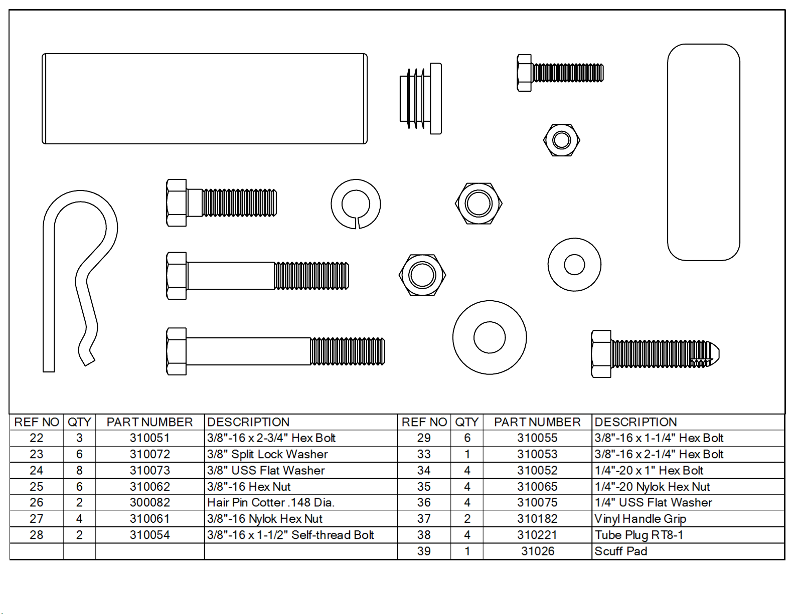
Hardware Contents
37
29
23
34
38
35
27
39
26
33
36
25
22
24 28
FOR MISSING PARTS, Call 1-800-652-2321, Monday - Friday, 8 a.m. - 5 p.m. E.S.T.
Page 4.
Page 5

Setting up Lift Mounting Hardware - Tractor Front
Tractor Lift can be used out of the box on all Craftsman tractors with bumpers or brush guards. Tractor Lift mounting hardware is provided. If
your tractor does not have a bumper or brush guard, follow the steps below:
Note: Left and Right sides are determined by standing behind tractor looking forward.
7R
29
27
7L
"X"
Remove,
add washer ( 24 ),
Step 1.
replace.
Step 1.
Remove existing bolt "X" and set aside. If tractor does not have
•
this bolt use supplied 3/8" x 1-1/4" bolt with 3/8 nylok nut.
Align holes in tractor mounting bars ( 7R & 7L ) to the front
•
left & right side frame holes of the tractor.
Insert hex head bolt ( 29 ) through inside front hole of frame,
•
through tractor mounting bar and secure with nylock nut ( 27 ).
24
26
6
26 38
Step 2.
Step 2.
Push tube plugs ( 38 ) into each end of lift tube ( 6 ).
•
Slide lift tube through cut-out in tractor mounting bars and
•
center.
Pin lift tube in place with one hair pin cotter ( 26 ) on each side
•
of mounting bar.
Add flat washer ( 24 ) under head of bolt removed in earlier
•
step and reinsert through tractor mounting bar and tighten.
For LT1000 & LT2000 series tractors, use self-thread bolts
•
( 28 ) in place of bolt ( 29 ) and nut ( 27 ).
FOR MISSING PARTS, Call 1-800-652-2321, Monday - Friday, 8 a.m. - 5 p.m. E.S.T.
Note: The mounting bars have been manufactured to attach to the
frames of most major front engine tractor brands. Additional
hardware has been included for attachment to non-Craftsman
brands.
Page 5.
Page 6

Assemble Tractor Lift
Attach Lift Tubes to Angle Frame
Lift tubes come pre-assembled. Attach lift tube assemblies ( 4 ) to angle frame ( 1 ) using bolts ( 22 ), flat washers ( 24 ), split lock washers ( 23 )
•
and hex nuts ( 25 ).
Secure rear of lift tube assembly ( 4 ) to angle frame ( 1 ) using bolts ( 29 ), flat washers ( 24 ), split lock washers ( 23 ) and hex
•
nuts ( 25 ).
Note: Over-tightening receiver bolts ( 22 ) could cause damage to lift tubes ( 4 ).
Determining the width between lift tubes.
22
24
4
5
Note: The higher the lift tube extensions (5)
are positioned, the harder the tractor will be to lift.
1
29
Front of Craftsman Zero Turn
Front of Craftsman Tractors
24
Brush guard bumper
(can also be used for
front of Craftsman tractor)
Push mower
25
23
D
A
B
C
A
D
C
B
23
25
Settings:
A. Push Mower
B. Brush guard / Bumper installed
C. Front of Craftsman Tractor
D. Front of Craftsman Zero Turn
FOR MISSING PARTS, Call 1-800-652-2321, Monday - Friday, 8 a.m. - 5 p.m. E.S.T.
Page 6.
Page 7

Assemble Tractor Lift
Attach Handle to Angle Frame
Step 1. Attach handle bottom ( 3 ) to angle frame ( 1 ) using hex bolt ( 22 ),
flat washer ( 24 ), split lock washer ( 23 ) and hex nut (25 ).
Step 2. Insert ring grip pin ( 30 ), as shown.
Step 3. Insert handle top ( 2 ) into handle bottom ( 3 ). Secure with hex
bolt ( 33 ), flat washer ( 24 ), split lock washer ( 23 ) and hex nut (25 ).
Step 4. Place handle grips ( 37 ) onto handle top tube ( 2 ). A little
soapy water will help grip slide onto tube easily.
22
24
IF HANDLE CANNOT BE
EASILY INSERTED, FLIP
HANDLE OVER AND
REINSERT.
37
2
Handle Top Tube
37
38
25
23
30
24
33
23
3
39
Peel off scuff pad (39)
backing and adhere to
back of handle.
25
30
30
38
Foot Bar Tube
1
FOR MISSING PARTS, Call 1-800-652-2321, Monday - Friday, 8 a.m. - 5 p.m. E.S.T.
Page 7.
Page 8

Assemble Tractor Lift
Attach Stabilizer Bar
Step 1. Slide stabilizer bar ( 8 ) onto foot bar tube as shown.
Step 2. Press snap button and slide stabilizer bar against handle.
Step 3. Insert ring grip pin ( 30 ) through stabilizer bar and handle top.
Foot bar tube
Snap button
8
30
FOR MISSING PARTS, Call 1-800-652-2321, Monday - Friday, 8 a.m. - 5 p.m. E.S.T.
Page 8.
Page 9

Page 10

OPERATION
Using the Tractor Lift
Step 3. Engaging Stabilizer Bar
Stabilizer bar MUST be engaged immediately after raising the tractor.
WARNING
: Failure to engage stabilizer bar may result in serious personal
injury and or property damage.
Remove ring grip pin ( 30 ) from tube handle. Press snap button
•
and slide stabilizer bar ( 8 ) from foot bar tube.
Turn stabilizer bar 180 degrees as shown at bottom of Figure 1.
•
Position stabilizer bar under base of unit between wheels.
•
Slide stabilizer bar back onto foot bar tube making sure the bar is
•
positioned back over snap button.
Tube Handle
Snap Button
Turn 180
30
8
Figure 1 Figure 2
FOR MISSING PARTS, Call 1-800-652-2321, Monday - Friday, 8 a.m. - 5 p.m. E.S.T.
Page 10.
Snap Button
Page 11

Repair Parts List
MODEL NUMBER - 610.24600
37
2
37
33
38
26
23
24
25
8
38
39
Peel off
backing,
adhere to
handle.
3
40
38
9
30
22
23
1
30
23
25
29
4
5
25
24
22
20
6
24
30
7L
35
4
5 9
25
38
7R
FOR MISSING PARTS, Call 1-800-652-2321, Monday - Friday, 8 a.m. - 5 p.m. E.S.T.
Page 11.
36
34
23
21
2026
Page 12

PRODUCT RECORD
In the space below record the model number and
purchase date of your cart. The model number can
be found on the front cover of the user guide.
Model Number___________________________.
Purchase Date___________________________.
Keep this booklet and your Sears receipt in a safe
place for future reference.
NOTES
ORDERING INFORMATION
After the one year warranty period all parts may
be ordered by calling Sears Service at
1-800-4MY-HOME (1-800-469-4663).
When ordering repair parts, always give the
following information:
Product - ___________________________.
•
Model Number - _____________________.
•
Part Number - *_____________________.
•
Part Description - *___________________.
•
*Found on the repair part list. Reference page 11.
Page 13

Get it fixed, at your home or ours!
Your Home
For expert troubleshooting and home solutions advice:
www.managemyhome.com
For repair – in your home – of all major brand appliances,
lawn and garden equipment, or heating and cooling systems,
no matter who made it, no matter who sold it!
For the replacement parts, accessories and
owner’s manuals that you need to do-it-yourself.
For Sears professional installation of home appliances
and items like garage door openers and water heaters.
®
1-800-4-MY-HOME
Call anytime, day or night (U.S.A. and Canada)
www.sears.com www.sears.ca
(1-800-469-4663)
Our Home
For repair of carry-in items like vacuums, lawn equipment,
and electronics, call anytime for the location of your nearest
Sears Parts & Repair Service Center
1-800-488-1222 (U.S.A.) 1-800-469-4663 (Canada)
www.sears.com www.sears.ca
To purchase a protection agreement on a product serviced by Sears:
1-800-827-6655 (U.S.A.) 1-800-361-6665 (Canada)
Para pedir servicio de reparación
a domicilio, y para ordenar piezas:
1-888-SU-HOGAR
(1-888-784-6427)
®
Au Canada pour service en français:
1-800-LE-FOYER
(1-800-533-6937)
www.sears.ca
MC
® Registered Trademark / TM Trademark /
® Marca Registrada / TM Marca de Fábrica / SM Marca de Servicio de Sears Brands, LLC
MC
Marque de commerce / MD Marque déposée de Sears Brands, LLC © Sears Brands, LLC
SM
Service Mark of Sears Brands, LLC
 Loading...