

Craftsman 580329180 Owner’s Manual
Owner's Manual
[CRAFTSHAN+I
120/240 Volt
Electric Start
7500 Watt
AC GENERATOR
Model No 580.329180
CusGemneraHt°lpline_
HOURS: Mon.- Fri. 8 a.m. to 5 p.m. (CT)
CAUTION:
Before using this product, read this
manual and follow all its Safety Rules
and Operating Instructions
Sears, Roebuck and Co, Hoffman Estates, IL 60179
Visit our Craftsman website: www.sears.com/craftsman
Part No. 186936 Draft 0 (8/16/2000) Printed in the U.S.A.
• Safety
• Assembly
• Operation
• Maintenance
• Parts
• Espan_l
Warranty .................................. 2
Safety Rules ............................... 3
Assembly ............................... 4-5
Operation .............................. 6-12
Product Specifications ....................... 13
Maintenance ........................... 13-16
Storage .................................. 17
Troubleshooting ............................ 18
Schematic/Wiring Diagram ................. 20-21
Replacement Parts ...................... 22-29
Emissions Warranty ......................... 30
EspaSol ............................... 31-51
How to Order Parts ................... Back Page
LIMITED WARRANTY FOR DELUXE PORTABLE GENERATORS
SEARS warrants to the original purchaser that the alternator and engine for its portable generator will be free
from defects in materials or workmanship for the items and period set forth below from the date of original
purchase. This warranty is not transferable and applies only to portable generators driven by the GN-Series
Sears warranted engine.
CONSUMER* COMMERCIAL*
Alternator 2 years (2nd year parts only) 1 year
Engine 2 years (2nd year parts only) 1 year
* NOTE: For the purpose of this warranty "Consumer Use" means personal residential household and
emergency use by original purchaser, not to be used as a primary source of power. "Commercial Use" means all
other uses, including rental, construction, commercial, and income producing purposes. Once a generator has
experienced commercial use, it shall thereafter be considered a commercial use generator for the purpose of
this warranty.
During said warranty period, SEARS will, at its option, repair or replace any part which, upon examination by
SEARS, is found to be defective under normal use and service**. Starting batteries are not warranted by
SEARS. All transportation costs under warranty, including return to the factory if necessary, are to be borne by
the purchaser and prepaid by him. This warranty does not cover normal maintenance and service and does not
apply to a generator set, alternator or engine, or parts which have been subjected to improper or unauthorized
installation or alteration, misuse, negligence, accident, overloading, overspeeding, improper maintenance, repair
or storage so as, in SEARS's judgment, to adversely affect its performance and reliability.
** NORMAL WEAR: As with all mechanical devices, engines need periodic parts service and replacement to
perform well. This warranty will not cover repair when normal use has exhausted the life of a part or engine.
THERE IS NO OTHER EXPRESS WARRANTY. SEARS HEREBY DISCLAIMS ANY AND ALL
IMPLIED WARRANTIES, INCLUDING BUT NOT LIMITED TO THOSE OF MERCHANTABILITY AND
FITNESS FOR A PARTICULAR PURPOSE TO THE EXTENT PERMITTED BY LAW. THE DURATION
OF ANY IMPLIED WARRANTIES WHICH CANNOT BE DISCLAIMED IS LIMITED TO THE TIME
PERIOD AS SPECIFIED IN THE EXPRESS WARRANTY. LIABILITY FOR CONSEQUENTIAL,
INCIDENTAL, OR SPECIAL DAMAGES UNDER ANY AND ALL WARRANTIES IS EXCLUDED.
Some states do not allow limitations on how long an implied warranty lasts, or the exclusion or limitation of
incidental or consequential damages, so the above limitations or exclusions may not apply to you. This warranty
gives you specific legal rights and you may also have other rights, which vary from state to state.
For service, see your nearest SEARS authorized warranty service facility. Warranty service can be performed
only by a SEARS authorized service facility. This warranty will not apply to service at any other facility. At the
time of requesting warranty service, evidence of original purchase date must be presented.
Sears, Roebuck and Co., D/817WA, Hoffman Estates, IL 60179
The engine exhaust from this product contains
chemicals known to the State of California
to cause cancer, birth defects,
or other reproductive harm.
,_ CAUTION! Before using this product, read this
manual and follow all Safety Rules and
Operating Instructions.
DANGER! This generator is designed for
outdoor use only. Do Not use this generator
inside any building or enclosure including the
generator compartment of a recreational vehicle
(RV). Fire or an explosion may result. No user
performed modifications, including venting of
exhaust and/or cooling ventilation, will eliminate
the danger. Also, allow at least two feet of
clearance on all sides of the generator while
operating the unit.
CAUTION! Always disconnect spark plug wire
and place the wire where it cannot contact the
spark plug to prevent accidental starting when
setting up, transporting, adjusting or making
repairs to your generator.
• The generator produces dangerously high voltage
that can cause extremely hazardous electrical
shock. Avoid contact with bare wires, terminals,
etc. Never permit any unqualified person to
operate or service the generator.
• Never handle any kind of electrical cord or device
while standing in water, while barefoot or while
hands or feet are wet. Dangerous electrical shock
will result.
• The National Electric Code requires the frame and
external electrically conductive parts of generator
be properly connected to an approved earth
ground. Local electrical codes may also require
proper grounding of the generator. Consult with a
local electrician for grounding requirements in your
area.
• Use a ground fault circuit interrupter in any damp
or highly conductive area (such as metal decking or
steel work).
• Do Not use worn, bare, frayed or otherwise
damaged electrical cord sets with the generator.
• Operate generator only on level surfaces and
where it will not be exposed to excessive moisture,
dirt, dust or corrosive vapors.
• Gasoline is highly FLAMMABLE and its vapors are
EXPLOSIVE. Do Not permit smoking, open flames,
sparks or heat in the vicinity while handling
gasoline. Avoid spilling gasoline on a hot engine.
Comply with all laws regulating storage and
handling of gasoline.
• Never add fuel while unit is running.
• Do Not overfill the fuel tank. Always allow room for
fuel expansion. If tank is overfilled, fuel can
overflow onto a hot engine and cause FIRE or an
EXPLOSION.
• Never store generator with fuel in tank where
gasoline vapors might reach an open flame or
spark or pilot light (as on a furnace, water heater or
clothes dryer). FIRE or EXPLOSION may result.
• Generator exhaust gases contain DEADLY carbon
monoxide gas. This dangerous gas, if breathed in
sufficient concentrations, can cause
unconsciousness or even death. Operate this
equipment only in the open air where adequate
ventilation is available.
• Allow at least 2 feet of clearance on all sides of
generator or you could damage the unit. Never
operate the unit inside any room or enclosure
where the free flow of cooling air into and out of the
unit might be obstructed. Review "Cold Weather
Operation" on page 10.
• Never start or stop the unit with electrical loads
connected to receptacles AND with connected
devices turned ON. Start the engine and let it
stabilize before connecting electrical loads.
Disconnect all electrical loads before shutting down
the generator.
• Do Not insert objects through units cooling slots.
• Never operate generator:
in rain; in any enclosed compartment; when
connected electrical devices overheat; if electrical
output is lost; if engine or generator sparks; if
flames or smoke are observed while unit is running;
if unit vibrates excessively.
NOTE: Your generator is equipped with a spark
arrester muffler. The spark arrester must be
maintained in effective working order by the owner/
operator. In the State of California, a spark arrester is
required by law (Section 4442 of the California Public
Resources Code). Other states may have similar laws.
Federal laws apply on federal lands.
,_ LOOK FOR THIS SYMBOL TO POINT OUT IMPORTANT SAFETY PRECAUTIONS. IT MEANS"ATTENTION!!! BECOME ALERT!!! YOUR SAFETY IS INVOLVED."
Your generator requires some assembly and is ready
for use after it has been properly serviced with the
recommended oil and fuel.
If you have any problems with the assembly of
your generator, please call the generator helpline
at 1-800-222-3136.
IMPORTANT: Any attempt to run the engine before it
has been serviced with the recommended oil will result
in an engine failure.
TO REMOVE GENERATOR FROM
CARTON
• Slice two corners at end of carton from top to
bottom so the panel can be folded down flat.
• Remove all packing material, carton fillers, etc.
• Remove the generator and tranfer switch container
from the shipping carton.
CARTON CONTENTS
• Generator
• Wheel kit
• Locking plug
• Engine oil
• Transfer switch components
• Battery tray components
• Battery charge cable
• Manual
Check all contents. If any parts are missing or
damaged, call the generator helpline at
1-800-222-3136.
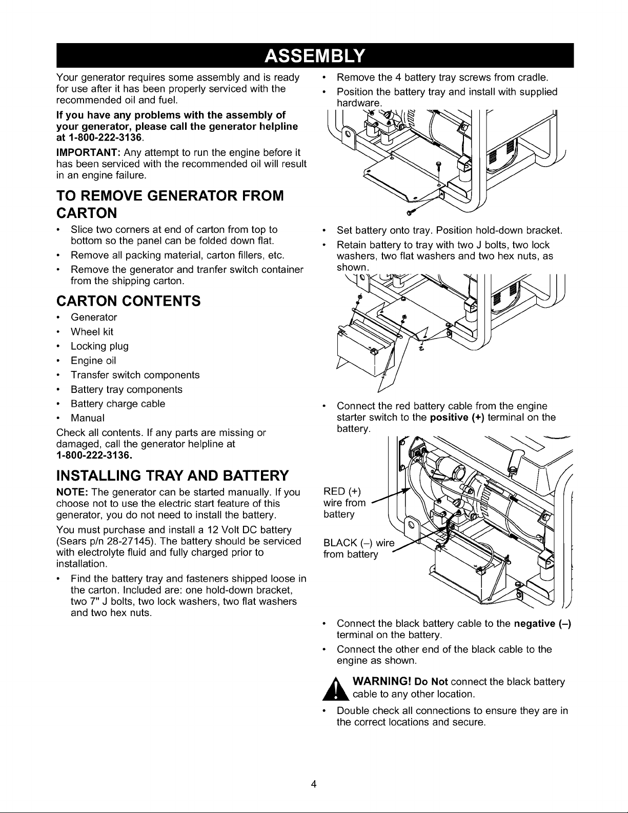
• Remove the 4 battery tray screws from cradle.
• Position the battery tray and install with supplied
hardware.
Set battery onto tray. Position hold-down bracket.
Retain battery to tray with two J bolts, two lock
washers, two flat washers and two hex nuts, as
shown.
Connect the red battery cable from the engine
starter switch to the positive (+) terminal on the
battery.
INSTALLING TRAY AND BATTERY
NOTE: The generator can be started manually. If you
choose not to use the electric start feature of this
generator, you do not need to install the battery.
You must purchase and install a 12 Volt DC battery
(Sears p/n 28-27145). The battery should be serviced
with electrolyte fluid and fully charged prior to
installation.
• Find the battery tray and fasteners shipped loose in
the carton. Included are: one hold-down bracket,
two 7" J bolts, two lock washers, two flat washers
and two hex nuts.
RED (+)
wire from J
battery
BLACK (-) wire
from battery
• Connect the black battery cable to the negative (-)
terminal on the battery.
• Connect the other end of the black cable to the
engine as shown.
A ARNING! Do Not connect the black battery
cable to any other location.
• Double check all connections to ensure they are in
the correct locations and secure.
4
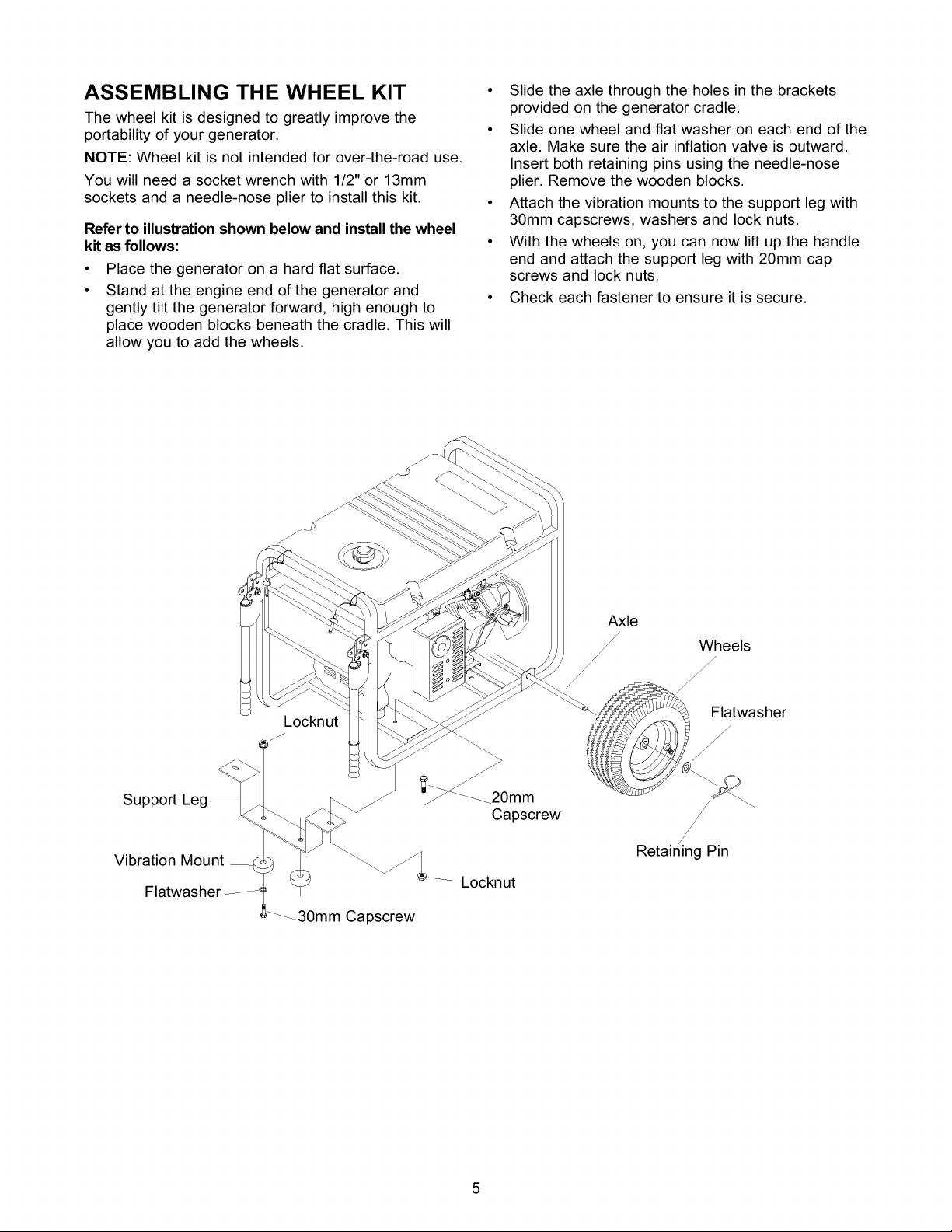
ASSEMBLING THE WHEEL KIT
The wheel kit is designed to greatly improve the
portability of your generator.
NOTE: Wheel kit is not intended for over-the-road use.
You will need a socket wrench with 1/2" or 13mm
sockets and a needle-nose plier to install this kit.
Refer to illustration shown below and install the wheel
kit as follows:
• Place the generator on a hard flat surface.
• Stand at the engine end of the generator and
gently tilt the generator forward, high enough to
place wooden blocks beneath the cradle. This will
allow you to add the wheels.
• Slide the axle through the holes in the brackets
provided on the generator cradle.
• Slide one wheel and flat washer on each end of the
axle. Make sure the air inflation valve is outward.
Insert both retaining pins using the needle-nose
plier. Remove the wooden blocks.
• Attach the vibration mounts to the support leg with
30mm capscrews, washers and lock nuts.
• With the wheels on, you can now lift up the handle
end and attach the support leg with 20mm cap
screws and lock nuts.
• Check each fastener to ensure it is secure.
Support
Vibration
Flatwasher
Locknut
_f
30mm Capscrew
__.20mm
Capscrew
Flatwasher
f
/
/
/
Retaining Pin
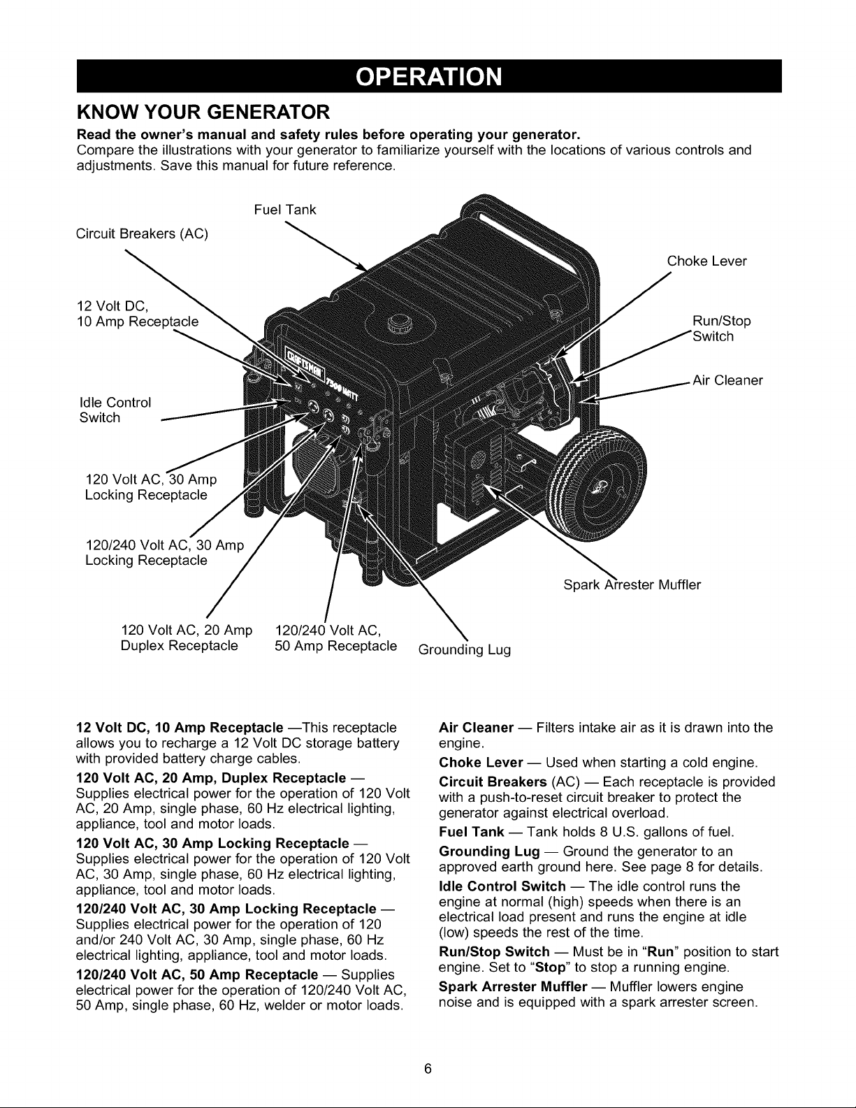
KNOW YOUR GENERATOR
Read the owner's manual and safety rules before operating your generator.
Compare the illustrations with your generator to familiarize yourself with the locations of various controls and
adjustments. Save this manual for future reference.
Fuel Tank
Circuit Breakers (AC)
Choke Lever
12 Volt DC,
10 Amp Receptacle
Idle Control
Switch
120 Volt AC, 30 Amp
Locking Receptacle
Run/Stop
Cleaner
120/240 Volt AC, 30 Amp
Locking Receptacle
120 Volt AC, 20 Amp
Duplex Receptacle
12 Volt DC, 10 Amp Receptacle --This receptacle
allows you to recharge a 12 Volt DC storage battery
with provided battery charge cables.
120 Volt AC, 20 Amp, Duplex Receptacle --
Supplies electrical power for the operation of 120 Volt
AC, 20 Amp, single phase, 60 Hz electrical lighting,
appliance, tool and motor loads.
120 Volt AC, 30 Amp Locking Receptacle --
Supplies electrical power for the operation of 120 Volt
AC, 30 Amp, single phase, 60 Hz electrical lighting,
appliance, tool and motor loads.
120/240 Volt AC, 30 Amp Locking Receptacle --
Supplies electrical power for the operation of 120
and/or 240 Volt AC, 30 Amp, single phase, 60 Hz
electrical lighting, appliance, tool and motor loads.
120/240 Volt AC, 50 Amp Receptacle -- Supplies
electrical power for the operation of 120/240 Volt AC,
50 Amp, single phase, 60 Hz, welder or motor loads.
120/240 Volt AC,
50 Amp Receptacle Grounding Lug
Spark A"_resterMuffler
Air Cleaner -- Filters intake air as it is drawn into the
engine.
Choke Lever-- Used when starting a cold engine.
Circuit Breakers (AC) -- Each receptacle is provided
with a push-to-reset circuit breaker to protect the
generator against electrical overload.
Fuel Tank -- Tank holds 8 U.S. gallons of fuel.
Grounding Lug -- Ground the generator to an
approved earth ground here. See page 8 for details.
Idle Control Switch -- The idle control runs the
engine at normal (high) speeds when there is an
electrical load present and runs the engine at idle
(low) speeds the rest of the time.
Run/Stop Switch -- Must be in "Run" position to start
engine. Set to "Stop" to stop a running engine.
Spark Arrester Muffler -- Muffler lowers engine
noise and is equipped with a spark arrester screen.
CONNECTOR PLUGS
120 Volt AC, 20 Amp, Duplex Receptacle
This is a 120 Volt outlet protected against overload by
a 20 Amp push-to-reset circuit breaker. Use each
socket to power 120 Volt AC, single phase, 60 Hz
electrical loads requiring up to a combined 2,400 watts
(2.4 kW) or 20 Amps of current. Use only high quality,
well-insulated, 3-wire grounded cord sets rated for
125 Volts at 20 Amps (or greater).
Use this receptacle to operate 120 Volt AC, 60 Hz,
single phase loads requiring up to 3,600 watts
(3.6 kW) of power at 30 Amps. The outlet is protected
by a 30 Amp push-to-reset circuit breaker.
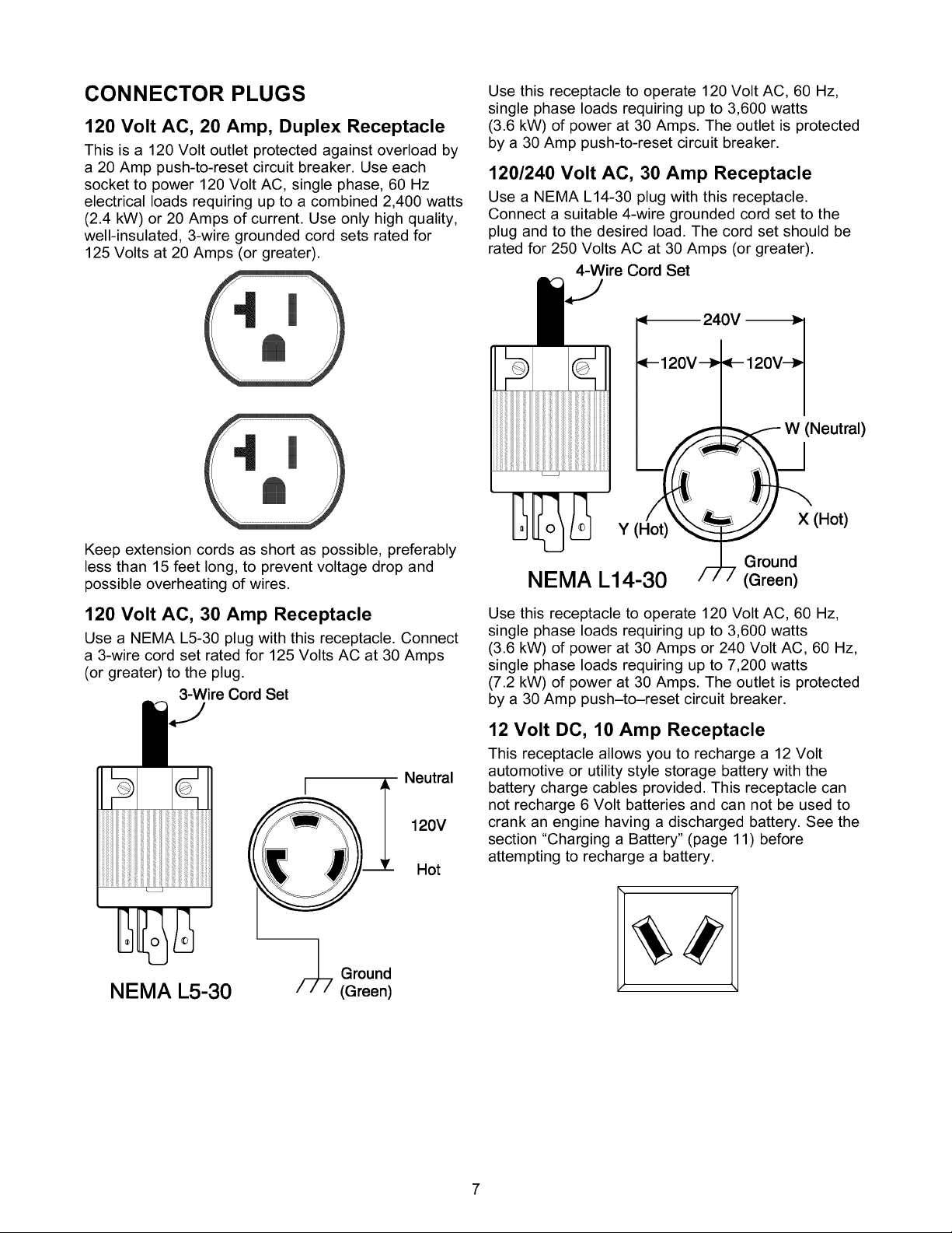
120/240 Volt AC, 30 Amp Receptacle
Use a NEMA L14-30 plug with this receptacle.
Connect a suitable 4-wire grounded cord set to the
plug and to the desired load. The cord set should be
rated for 250 Volts AC at 30 Amps (or greater).
4-Wire Cord Set
120V--_
(Neutral)
Keep extension cords as short as possible, preferably
less than 15 feet long, to prevent voltage drop and
possible overheating of wires.
120 Volt AC, 30 Amp Receptacle
Use a NEMA L5-30 plug with this receptacle. Connect
a 3-wire cord set rated for 125 Volts AC at 30 Amps
(or greater) to the plug.
3-Wire Cord Set
Neutral
120V
Hot
Y (Hot)
Ground
NEMA L14-30
Use this receptacle to operate 120 Volt AC, 60 Hz,
single phase loads requiring up to 3,600 watts
(3.6 kW) of power at 30 Amps or 240 Volt AC, 60 Hz,
single phase loads requiring up to 7,200 watts
(7.2 kW) of power at 30 Amps. The outlet is protected
by a 30 Amp push-to-reset circuit breaker.
(Green)
X (Hot)
12 Volt DC, 10 Amp Receptacle
This receptacle allows you to recharge a 12 Volt
automotive or utility style storage battery with the
battery charge cables provided. This receptacle can
not recharge 6 Volt batteries and can not be used to
crank an engine having a discharged battery. See the
section "Charging a Battery" (page 11) before
attempting to recharge a battery.
NEMA L5-30
/__ Ground
(Green)
120/240 Volt AC, 50 Amp Receptacle
Use a NEMA 14-50 plug with this receptacle. Connect
a 4-wire cord set rated for 250 Volts AC at 50 Amps to
the plug.
240 Volts AC
Frame Ground
||
HOW TO USE YOUR GENERATOR
If you have any problems operating your generator,
please call the generator helpline at 1-800-222-3136.
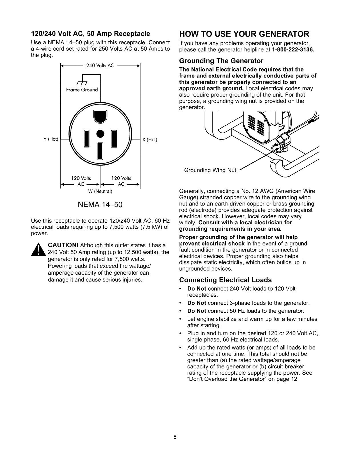
Grounding The Generator
The National Electrical Code requires that the
frame and external electrically conductive parts of
this generator be properly connected to an
approved earth ground. Local electrical codes may
also require proper grounding of the unit. For that
purpose, a grounding wing nut is provided on the
generator.
Y (Hot)
120 Volts _ 120 Volts
W (Neutral)
X (Hot)
NEMA 14-50
Use this receptacle to operate 120/240 Volt AC, 60 Hz
electrical loads requiring up to 7,500 watts (7.5 kW) of
power.
_ AUTION! Although this outlet states it has a
240 Volt 50 Amp rating (up to 12,500 watts), the
generator is only rated for 7,500 watts.
Powering loads that exceed the wattage/
amperage capacity of the generator can
damage it and cause serious injuries.
Grounding Wing Nut
Generally, connecting a No. 12 AWG (American Wire
Gauge) stranded copper wire to the grounding wing
nut and to an earth-driven copper or brass grounding
rod (electrode) provides adequate protection against
electrical shock. However, local codes may vary
widely. Consult with a local electrician for
grounding requirements in your area.
Proper grounding of the generator will help
prevent electrical shock in the event of a ground
fault condition in the generator or in connected
electrical devices. Proper grounding also helps
dissipate static electricity, which often builds up in
ungrounded devices.
Connecting Electrical Loads
• Do Not connect 240 Volt loads to 120 Volt
receptacles.
• Do Not connect 3-phase loads to the generator.
• Do Not connect 50 Hz loads to the generator.
• Let engine stabilize and warm up for a few minutes
after starting.
• Plug in and turn on the desired 120 or 240 Volt AC,
single phase, 60 Hz electrical loads.
• Add up the rated watts (or amps) of all loads to be
connected at one time. This total should not be
greater than (a) the rated wattage/amperage
capacity of the generator or (b) circuit breaker
rating of the receptacle supplying the power. See
"Don't Overload the Generator" on page 12.
BEFORE STARTING THE
GENERATOR
To operate the generator you will need to first add
engine oil and gasoline, as follows:
Add Engine Oil
NOTE: When adding oil to the engine crankcase in
the future, use only high quality detergent oil rated
with API service classification SF or SG SAE 30
weight. Use no special additives.
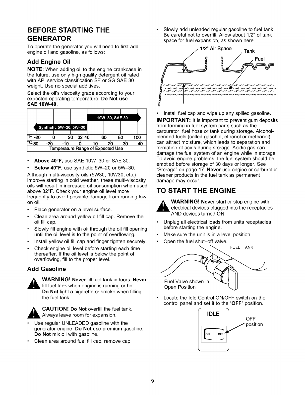
Select the oil's viscosity grade according to your
expected operating temperature. Do Not use
SAE 10W-40.
E,,._h"r_ r_E,."kvlv_5,'.[oL_kvlv_:tll
°F -20 0 20 32 40 60 80 100
°C_ o -2'0 -io 6 i'o 5o 4'0
TemperatureRangeofExpectedUse
• Above 40°F, use SAE 10W-30 or SAE 30.
• Below 40°F, use synthetic 5W-20 or 5W-30.
Although multi-viscosity oils (5W30, 10W30, etc.)
improve starting in cold weather, these multi-viscosity
oils will result in increased oil consumption when used
above 32°F. Check your engine oil level more
frequently to avoid possible damage from running low
on oil.
• Place generator on a level surface.
• Clean area around yellow oil fill cap. Remove the
oil fill cap.
• Slowly fill engine with oil through the oil fill opening
until the oil level is to the point of overflowing.
• Install yellow oil fill cap and finger tighten securely.
• Check engine oil level before starting each time
thereafter. If the oil level is below the point of
overflowing, fill to the proper level.
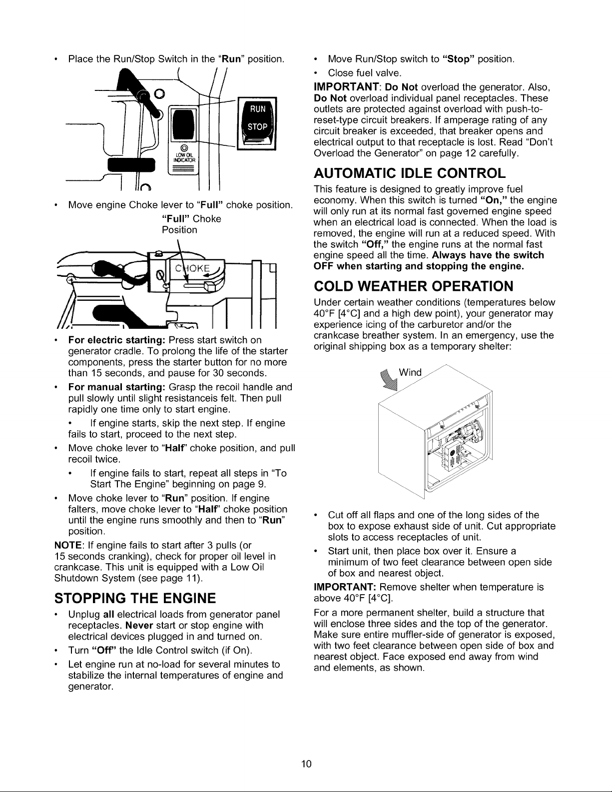
Slowly add unleaded regular gasoline to fuel tank.
Be careful not to overfill. Allow about 1/2" of tank
space for fuel expansion, as shown here.
1/2" Air Space Tank
Fuel
• Install fuel cap and wipe up any spilled gasoline.
IMPORTANT: It is important to prevent gum deposits
from forming in fuel system parts such as the
carburetor, fuel hose or tank during storage. Alcohol-
blended fuels (called gasohol, ethanol or methanol)
can attract moisture, which leads to separation and
formation of acids during storage. Acidic gas can
damage the fuel system of an engine while in storage.
To avoid engine problems, the fuel system should be
emptied before storage of 30 days or longer. See
"Storage" on page 17. Never use engine or carburetor
cleaner products in the fuel tank as permanent
damage may occur.
TO START THE ENGINE
A ARNING! Never start or stop engine with
electrical devices plugged into the receptacles
AND devices turned ON.
Unplug all electrical loads from units receptacles
before starting the engine.
Make sure the unit is in a level position.
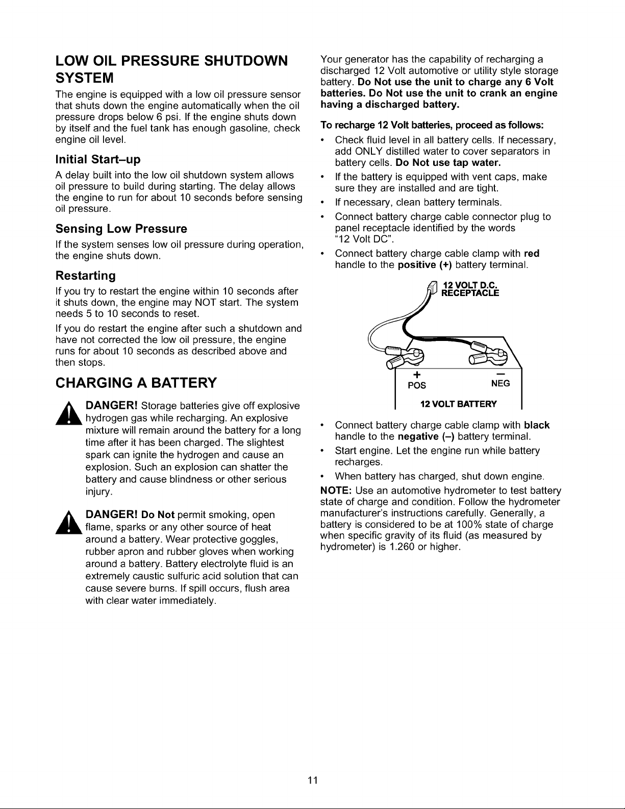
Open the fuel shut-off valve.
Add Gasoline
A ARNING! Never fill fuel tank indoors. Never
fill fuel tank when engine is running or hot.
Do Not light a cigarette or smoke when filling
the fuel tank.
A CAUTION! Do Not overfill the fuel tank.
Always leave room for expansion.
• Use regular UNLEADED gasoline with the
generator engine. Do Not use premium gasoline.
Do Not mix oil with gasoline.
• Clean area around fuel fill cap, remove cap.
FUEL TANK
FuelValveshown in "_--_ II
Open Position
Locate the Idle Control ON/OFF switch on the
control panel and set it to the "OFF" position.
Lu
IDLE
OFF
position
PlacetheRun/StopSwitchinthe"Run"position.
Move engine Choke lever to "Full" choke position.
"Full" Choke
Position
• For electric starting: Press start switch on
generator cradle. To prolong the life of the starter
components, press the starter button for no more
than 15 seconds, and pause for 30 seconds.
• For manual starting: Grasp the recoil handle and
pull slowly until slight resistanceis felt. Then pull
rapidly one time only to start engine.
• If engine starts, skip the next step. If engine
fails to start, proceed to the next step.
• Move choke lever to "Half" choke position, and pull
recoil twice.
• If engine fails to start, repeat all steps in "To
Start The Engine" beginning on page 9.
• Move choke lever to "Run" position. Ifengine
falters, move choke lever to "Half" choke position
until the engine runs smoothly and then to "Run"
position.
NOTE: If engine fails to start after 3 pulls (or
15 seconds cranking), check for proper oil level in
crankcase. This unit is equipped with a Low Oil
Shutdown System (see page 11).
STOPPING THE ENGINE
• Unplug all electrical loads from generator panel
receptacles. Never start or stop engine with
electrical devices plugged in and turned on.
• Turn "Off" the Idle Control switch (if On).
• Let engine run at no-load for several minutes to
stabilize the internal temperatures of engine and
generator.
• Move Run/Stop switch to "Stop" position.
• Close fuel valve.
IMPORTANT: Do Not overload the generator. Also,
Do Not overload individual panel receptacles. These
outlets are protected against overload with push-to-
reset-type circuit breakers. If amperage rating of any
circuit breaker is exceeded, that breaker opens and
electrical output to that receptacle is lost. Read "Don't
Overload the Generator" on page 12 carefully.
AUTOMATIC IDLE CONTROL
This feature is designed to greatly improve fuel
economy. When this switch is turned "On," the engine
will only run at its normal fast governed engine speed
when an electrical load is connected. When the load is
removed, the engine will run at a reduced speed. With
the switch "Off," the engine runs at the normal fast
engine speed all the time. Always have the switch
OFF when starting and stopping the engine.
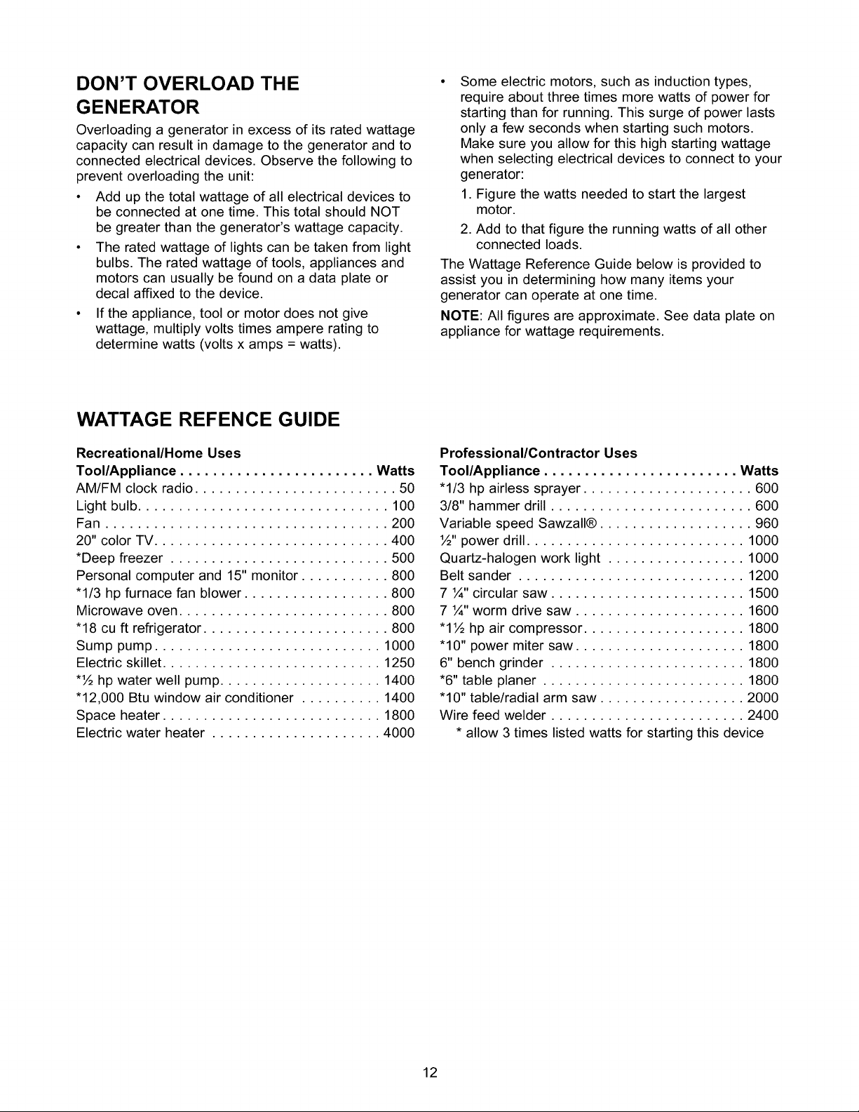
COLD WEATHER OPERATION
Under certain weather conditions (temperatures below
40°F [4°C] and a high dew point), your generator may
experience icing of the carburetor and/or the
crankcase breather system. In an emergency, use the
original shipping box as a temporary shelter:
• Cut off all flaps and one of the long sides of the
box to expose exhaust side of unit. Cut appropriate
slots to access receptacles of unit.
• Start unit, then place box over it. Ensure a
minimum of two feet clearance between open side
of box and nearest object.
IMPORTANT: Remove shelter when temperature is
above 40°F [4°C].
For a more permanent shelter, build a structure that
will enclose three sides and the top of the generator.
Make sure entire muffler-side of generator is exposed,
with two feet clearance between open side of box and
nearest object. Face exposed end away from wind
and elements, as shown.
10
LOW OIL PRESSURE SHUTDOWN
SYSTEM
The engine is equipped with a low oil pressure sensor
that shuts down the engine automatically when the oil
pressure drops below 6 psi. If the engine shuts down
by itself and the fuel tank has enough gasoline, check
engine oil level.
Initial Start-up
A delay built into the low oil shutdown system allows
oil pressure to build during starting. The delay allows
the engine to run for about 10 seconds before sensing
oil pressure.
Sensing Low Pressure
If the system senses low oil pressure during operation,
the engine shuts down.
Restarting
If you try to restart the engine within 10 seconds after
it shuts down, the engine may NOT start. The system
needs 5 to 10 seconds to reset.
If you do restart the engine after such a shutdown and
have not corrected the low oil pressure, the engine
runs for about 10 seconds as described above and
then stops.
CHARGING A BATTERY
Your generator has the capability of recharging a
discharged 12 Volt automotive or utility style storage
battery. Do Not use the unit to charge any 6 Volt
batteries. Do Not use the unit to crank an engine
having a discharged battery.
To recharge 12 Volt batteries, proceed as follows:
• Check fluid level in all battery cells. If necessary,
add ONLY distilled water to cover separators in
battery cells. Do Not use tap water.
• If the battery is equipped with vent caps, make
sure they are installed and are tight.
• If necessary, clean battery terminals.
• Connect battery charge cable connector plug to
panel receptacle identified by the words
"12 Volt DC".
• Connect battery charge cable clamp with red
handle to the positive (+) battery terminal.
12 VOLT D.C.
RECEPTACLE
+
POS NEG
DANGER! Storage batteries give off explosive
hydrogen gas while recharging. An explosive
mixture will remain around the battery for a long
time after it has been charged. The slightest
spark can ignite the hydrogen and cause an
explosion. Such an explosion can shatter the
battery and cause blindness or other serious
injury.
DANGER! Do Not permit smoking, open
flame, sparks or any other source of heat
around a battery. Wear protective goggles,
rubber apron and rubber gloves when working
around a battery. Battery electrolyte fluid is an
extremely caustic sulfuric acid solution that can
cause severe burns. If spill occurs, flush area
with clear water immediately.
12 VOLT BATTERY
• Connect battery charge cable clamp with black
handle to the negative (-) battery terminal.
• Start engine. Let the engine run while battery
recharges.
• When battery has charged, shut down engine.
NOTE: Use an automotive hydrometer to test battery
state of charge and condition. Follow the hydrometer
manufacturer's instructions carefully. Generally, a
battery is considered to be at 100% state of charge
when specific gravity of its fluid (as measured by
hydrometer) is 1.260 or higher.
11
DON'T OVERLOAD THE
GENERATOR
Overloading a generator in excess of its rated wattage
capacity can result in damage to the generator and to
connected electrical devices. Observe the following to
prevent overloading the unit:
• Add up the total wattage of all electrical devices to
be connected at one time. This total should NOT
be greater than the generator's wattage capacity.
• The rated wattage of lights can be taken from light
bulbs. The rated wattage of tools, appliances and
motors can usually be found on a data plate or
decal affixed to the device.
• Ifthe appliance, tool or motor does not give
wattage, multiply volts times ampere rating to
determine watts (volts x amps = watts).
WATTAGE REFENCE GUIDE
• Some electric motors, such as induction types,
require about three times more watts of power for
starting than for running. This surge of power lasts
only a few seconds when starting such motors.
Make sure you allow for this high starting wattage
when selecting electrical devices to connect to your
generator:
1. Figure the watts needed to start the largest
motor.
2. Add to that figure the running watts of all other
connected loads.
The Wattage Reference Guide below is provided to
assist you in determining how many items your
generator can operate at one time.
NOTE: All figures are approximate. See data plate on
appliance for wattage requirements.
Recreational/Home Uses
Tool/Appliance ........................ Watts
AM/FM clock radio ......................... 50
Light bulb ............................... 100
Fan ................................... 200
20" color TV ............................. 400
*Deep freezer ........................... 500
Personal computer and 15" monitor ........... 800
"1/3 hp furnace fan blower .................. 800
Microwave oven .......................... 800
"18 cu ft refrigerator ....................... 800
Sump pump ............................ 1000
Electric skillet ........................... 1250
*½ hp water well pump .................... 1400
"12,000 Btu window air conditioner .......... 1400
Space heater ........................... 1800
Electric water heater ..................... 4000
Professional/Contractor Uses
Tool/Appliance ........................ Watts
"1/3 hp airless sprayer ..................... 600
3/8" hammer drill ......................... 600
Variable speed Sawzall® ................... 960
½" power drill ........................... 1000
Quartz-halogen work light ................. 1000
Belt sander ............................ 1200
7 ¼" circular saw ........................ 1500
7 ¼" worm drive saw ..................... 1600
"1½ hp air compressor .................... 1800
"10" power miter saw ..................... 1800
6" bench grinder ........................ 1800
*6" table planer ......................... 1800
"10" table/radial arm saw .................. 2000
Wire feed welder ........................ 2400
* allow 3 times listed watts for starting this device
12
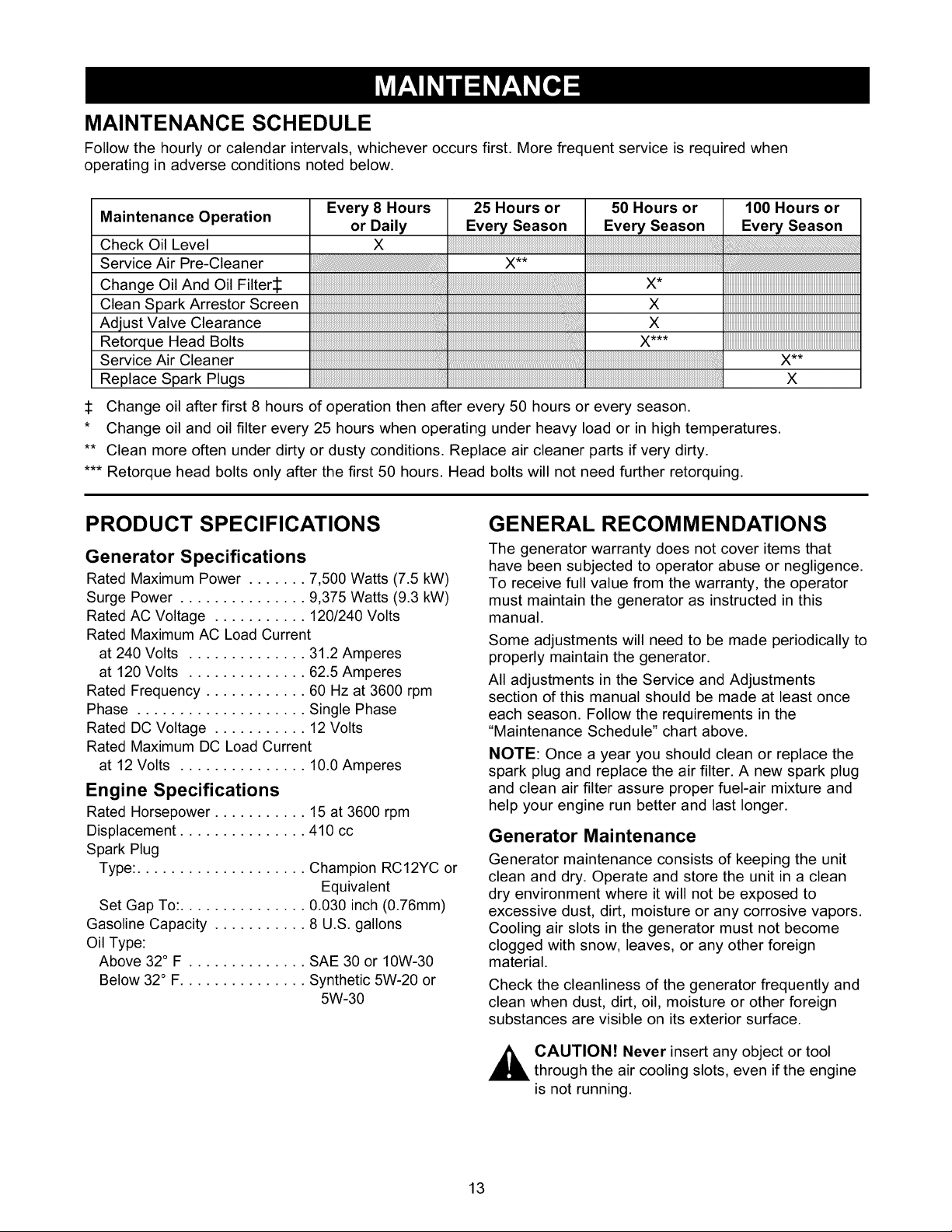
MAINTENANCE SCHEDULE
Follow the hourly or calendar intervals, whichever occurs first. More frequent service is required when
operating in adverse conditions noted below.
Maintenance Operation
Check Oil Level
Service Air Pre-Cleaner
Change Oil And Oil Filters
Clean Spark Arrestor Screen
Adjust Valve Clearance
Retorque Head Bolts
Service Air Cleaner
Replace Spark Plugs
Change oil after first 8 hours of operation then after every 50 hours or every season.
* Change oil and oil filter every 25 hours when operating under heavy load or in high temperatures.
** Clean more often under dirty or dusty conditions. Replace air cleaner parts if very dirty.
*** Retorque head bolts only after the first 50 hours. Head bolts will not need further retorquing.
Every 8 Hours
or Daily
X
PRODUCT SPECIFICATIONS
Generator Specifications
Rated Maximum Power ....... 7,500 Watts (7.5 kW)
Surge Power ............... 9,375 Watts (9.3 kW)
Rated AC Voltage ........... 120/240 Volts
Rated Maximum AC Load Current
at 240 Volts .............. 31.2 Amperes
at 120 Volts .............. 62.5 Amperes
Rated Frequency ............ 60 Hz at 3600 rpm
Phase .................... Single Phase
Rated DC Voltage ........... 12 Volts
Rated Maximum DC Load Current
at 12 Volts ............... 10.0 Amperes
Engine Specifications
Rated Horsepower ........... 15 at 3600 rpm
Displacement ............... 410 cc
Spark Plug
Type: .................... Champion RC12YC or
Equivalent
Set Gap To:............... 0.030 inch (0.76mm)
Gasoline Capacity ........... 8 U.S. gallons
Oil Type:
Above 32° F .............. SAE 30 or 10W-30
Below 32° F............... Synthetic 5W-20 or
5W-30
25 Hours or 50 Hours or 100 Hours or
Every Season Every Season Every Season
x**
×
×
GENERAL RECOMMENDATIONS
The generator warranty does not cover items that
have been subjected to operator abuse or negligence.
To receive full value from the warranty, the operator
must maintain the generator as instructed in this
manual.
Some adjustments will need to be made periodically to
properly maintain the generator.
All adjustments in the Service and Adjustments
section of this manual should be made at least once
each season. Follow the requirements in the
"Maintenance Schedule" chart above.
NOTE: Once a year you should clean or replace the
spark plug and replace the air filter. A new spark plug
and clean air filter assure proper fuel-air mixture and
help your engine run better and last longer.
Generator Maintenance
Generator maintenance consists of keeping the unit
clean and dry. Operate and store the unit in a clean
dry environment where it will not be exposed to
excessive dust, dirt, moisture or any corrosive vapors.
Cooling air slots in the generator must not become
clogged with snow, leaves, or any other foreign
material.
Check the cleanliness of the generator frequently and
clean when dust, dirt, oil, moisture or other foreign
substances are visible on its exterior surface.
X**
X
,_ CAUTION! Never insert any object or tool
through the air cooling slots, even if the engine
is not running.
13
NOTE:DoNotuseagardenhosetocleangenerator.
Watercanentertheenginefuelsystemandcause
problems.Inaddition,ifwaterentersthegenerator
throughcoolingairslots,somewaterwillberetained
invoidsandcracksoftherotorandstatorwinding
insulation.Wateranddirtbuilduponthegenerator
internalwindingswilleventuallydecreasethe
insulationresistanceofthesewindings.
ToCleantheGenerator:
• Usea dampclothtowipeexteriorsurfacesclean.
• Asoft,bristlebrushmaybeusedto loosencaked
ondirt,oil,etc.
• Avacuumcleanermaybeusedtopickuploose
dirtanddebris.
• Lowpressureair(nottoexceed25psi)maybe
usedtoblowawaydirt.Inspectcoolingairslots
andopeningsonthegenerator.Theseopenings
mustbekeptcleanandunobstructed.
Engine Maintenance
_ ANGER! When working on the generator,
always disconnect negative cable from battery.
Also disconnect spark plug wires from spark
plug and keep wire away from spark plug.
• Coat gasket of new filter with fresh clean engine
oil. Turn filter clockwise until gasket contacts tightly
with filter adapter. Then tighten 3/4 turn more.
• Fill engine with recommended oil. (See "BEFORE
STARTING THE Generator" on page 9 for oil
recommendations).
• Install the oil fill cap and tighten securely.
• Wipe up any spilled oil.
Replacing the Spark Plug
Use the recommended spark plug gapped to 0.76 mm
(0.030 in.). Replace the plug every 100 hours of
operation or once each year, whichever comes first.
This will help your engine start easier and run better.
1. Stop the engine and pull the spark plug wire off of
the spark plug.
2. Clean the area around the spark plug and remove
it from the cylinder head.
3. Set the spark plug's gap to 0.76 mm (0.030 in.).
Install the correctly gapped spark plug into the
cylinder head.
Checking Oil Level
See "BEFORE STARTING THE GENERATOR" on
page 9 for information on checking the oil level. The
oil level should be checked before each use, or at
least every eight hours of operation. Keep the oil
level maintained.
Changing the Oil and Oil Filter
Change the oil and filter after the first eight hours of
operation. Change the oil every 50 hours
thereafter. If you are running this unit under dirty or
dusty conditions, or in extremely hot weather, change
the oil more often.
Use the following instructions to change the oil
while the engine is still warm:
• Clean area around oil drain plug and oil fill cap.
• Remove oil fill cap and oil drain plug. Drain oil
completely into a suitable container.
• When oil has completely drained, install oil drain
plug and tighten securely.
• Place a suitable container beneath the oil filter and
turn filter counterclockwise to remove. Discard
according to local regulations.
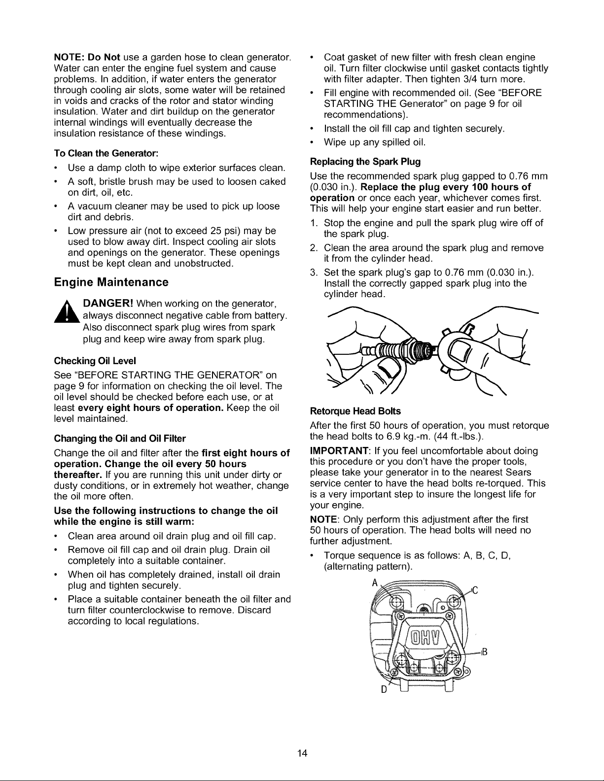
Retorque Head Bolts
After the first 50 hours of operation, you must retorque
the head bolts to 6.9 kg.-m. (44 ft.-Ibs.).
IMPORTANT: If you feel uncomfortable about doing
this procedure or you don't have the proper tools,
please take your generator in to the nearest Sears
service center to have the head bolts re-torqued. This
is a very important step to insure the longest life for
your engine.
NOTE: Only perform this adjustment after the first
50 hours of operation. The head bolts will need no
further adjustment.
• Torque sequence is as follows: A, B, C, D,
(alternating pattern).
Ai
14
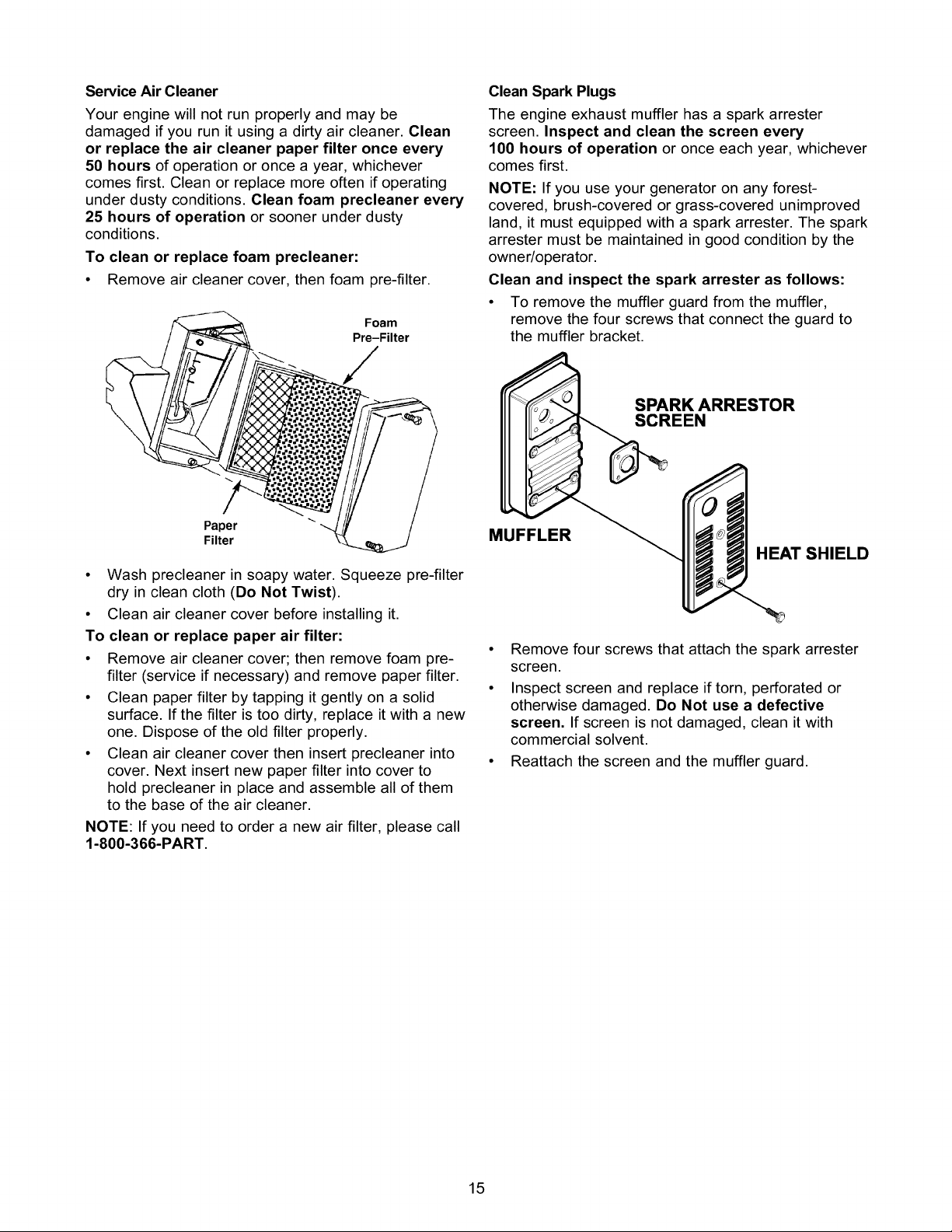
Service Air Cleaner
Your engine will not run properly and may be
damaged if you run it using a dirty air cleaner. Clean
or replace the air cleaner paper filter once every
50 hours of operation or once a year, whichever
comes first. Clean or replace more often if operating
under dusty conditions. Clean foam precleaner every
25 hours of operation or sooner under dusty
conditions.
To clean or replace foam precleaner:
• Remove air cleaner cover, then foam pre-filter.
Foam
Pre-Filter
Clean Spark Plugs
The engine exhaust muffler has a spark arrester
screen. Inspect and clean the screen every
100 hours of operation or once each year, whichever
comes first.
NOTE: If you use your generator on any forest-
covered, brush-covered or grass-covered unimproved
land, it must equipped with a spark arrester. The spark
arrester must be maintained in good condition by the
owner/operator.
Clean and inspect the spark arrester as follows:
• To remove the muffler guard from the muffler,
remove the four screws that connect the guard to
the muffler bracket.
SPARK ARRESTOR
SCREEN
Paper
Filter
• Wash precleaner in soapy water. Squeeze pre-filter
dry in clean cloth (Do Not Twist).
• Clean air cleaner cover before installing it.
To clean or replace paper air filter:
• Remove air cleaner cover; then remove foam pre-
filter (service if necessary) and remove paper filter.
• Clean paper filter by tapping it gently on a solid
surface. If the filter is too dirty, replace it with a new
one. Dispose of the old filter properly.
• Clean air cleaner cover then insert precleaner into
cover. Next insert new paper filter into cover to
hold precleaner in place and assemble all of them
to the base of the air cleaner.
NOTE: If you need to order a new air filter, please call
1-800-366-PART.
MUFFLER
HEAT SHIELD
• Remove four screws that attach the spark arrester
screen.
• Inspect screen and replace if torn, perforated or
otherwise damaged. Do Not use a defective
screen. If screen is not damaged, clean it with
commercial solvent.
• Reattach the screen and the muffler guard.
15
Adjusting Valve Clearance
After the first 50 hours of operation, you should
adjust the valve clearance in the engine.
IMPORTANT: If you feel uncomfortable about doing
this procedure or you don't have the proper tools,
please take your generator in to the nearest Sears
service center to have the valve clearance adjusted.
This is a very important step to insure longest life for
your engine.
To adjust valve clearance:
• Make sure the engine is at room temperature.
• Make sure that the spark plug wire is removed from
the spark plug and out of the way.
• Remove the breather tube from the valve cover.
• Remove the four screws attaching the valve cover
with a #2 or 3 phillips screwdriver.
• Make sure the piston is at Top Dead Center (TDC)
of its compression stroke (both valves closed). To
get the piston at TDC, pull on the recoil handle
slowly while watching the piston through the spark
plug hole. As you pull on the recoil handle, the
piston should move up and down. The piston is at
TDC when it is up as high as it can go.
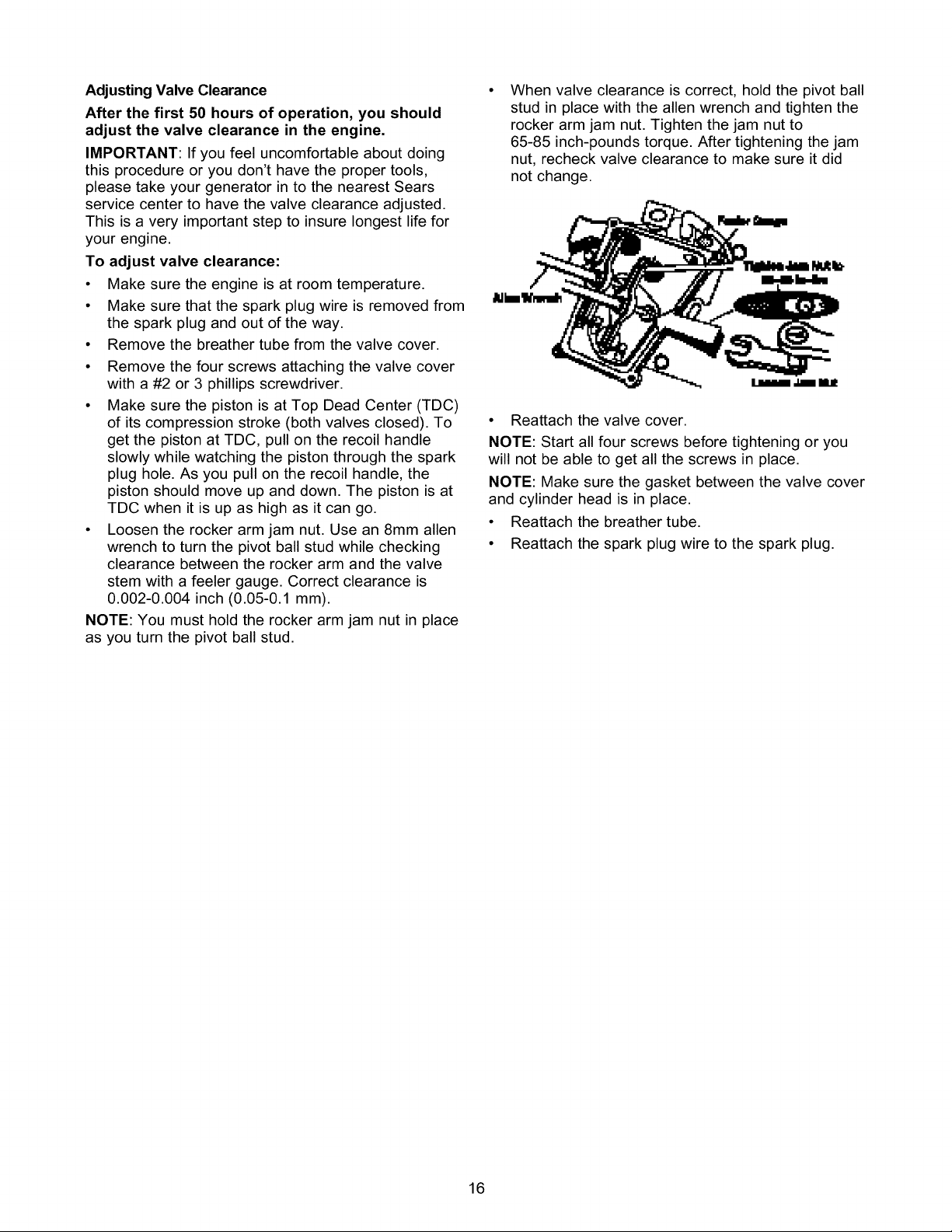
• Loosen the rocker arm jam nut. Use an 8mm allen
wrench to turn the pivot ball stud while checking
clearance between the rocker arm and the valve
stem with a feeler gauge. Correct clearance is
0.002-0.004 inch (0.05-0.1 mm).
NOTE: You must hold the rocker arm jam nut in place
as you turn the pivot ball stud.
When valve clearance is correct, hold the pivot ball
stud in place with the allen wrench and tighten the
rocker arm jam nut. Tighten the jam nut to
65-85 inch-pounds torque. After tightening the jam
nut, recheck valve clearance to make sure it did
not change.
• Reattach the valve cover.
NOTE: Start all four screws before tightening or you
will not be able to get all the screws in place.
NOTE: Make sure the gasket between the valve cover
and cylinder head is in place.
• Reattach the breather tube.
• Reattach the spark plug wire to the spark plug.
16
 Loading...