

Page 1
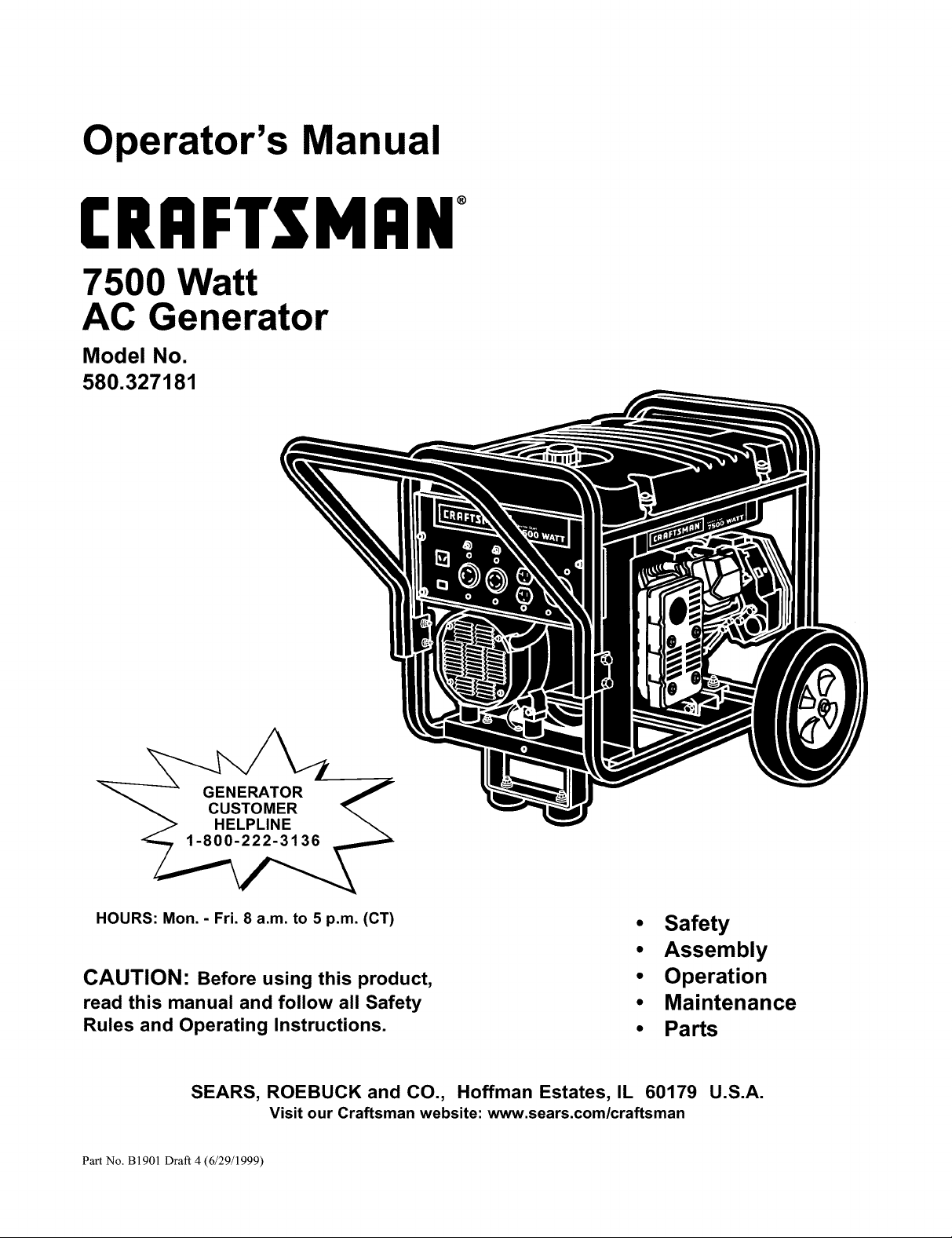
Operator's Manual
CRAFTSMAN°
7500 Watt
AC Generator
Model No.
580.327181
GENERATOR 7
CUSTOMER
HELPLINE
HOURS: Mon.- Fri. 8 a.m. to 5 p.m. (CT)
CAUTION: Before using this product,
read this manual and follow all Safety
Rules and Operating Instructions.
SEARS, ROEBUCK and CO., Hoffman Estates, IL 60179 U.S.A.
Visit our Craftsman website: www.sears.com/craftsman
Part No, B1901 Draft 4 (6/29/1999)
• Safety
• Assembly
• Operation
• Maintenance
• Parts
Page 2
Safety Rules ........................... 2-3
Assembly .............................. 4-5
Operation ............................. 6-10
Maintenance ......................... 11-13
Storage ................................ 14
Troubleshooting ......................... 15
Replacement Parts .................... 17-27
HOW TO ORDER PARTS .......... BACK PAGE
Specifications ........................... 11
LIMITED WARRANTY FOR DELUXE PORTABLE GENERATORS
SEARS warrants to the original purchaser that the alternator and engine for its portable generator will be free from defects in
materials or workmanship for the items and period set forth below from the date of original purchase. This warranty is not
transferable and applies only to portable generators driven by the GN-Series Sears warranted engine.
Alternator 2 years (2nd year parts only) 1 year
Engine 2 years (2nd year parts only) 1 year
* NOTE: For the purpose of this warranty "Consumer Use" means personal residential household and emergency use by
original purchaser, not to be used as a primary source of power. "Commercial Use" means all other uses, including rental,
construction, commercial, and income producing purposes. Once a generator has experienced commercial use, it shall
thereafter be considered a commercial use generator for the purpose of this warranty.
During said warranty period, SEARS will, at its option, repair or replace any part which, upon examination by SEARS, is
found to be defective under normal use and service**. Starting batteries are not warranted by SEARS. All transportation
costs under warranty, including return to the factory if necessary, are to be borne by the purchaser and prepaid by him. This
warranty does not cover normal maintenance and service and does not apply to a generator set, alternator or engine, or
parts which have been subjected to improper or unauthorized installation or alteration, misuse, negligence, accident, over-
loading, overspeeding, improper maintenance, repair or storage so as, in SEARS's judgment, to adversely affect its perfor-
mance and reliability.
** NORMAL WEAR: As with all mechanical devices, engines need periodic parts service and replacement to perform well.
This warranty will not cover repair when normal use has exhausted the life of a part or engine.
THERE IS NO OTHER EXPRESS WARRANTY. SEARS HEREBY DISCLAIMS ANY AND ALL IMPLIED WARRANTIES,
INCLUDING BUT NOT LIMITED TO THOSE OF MERCHANTABILITY AND FITNESS FOR A PARTICULAR PURPOSE TO
THE EXTENT PERMITTED BY LAW. THE DURATION OF ANY IMPLIED WARRANTIES WHICH CANNOT BE DIS-
CLAIMED IS LIMITED TO THE TIME PERIOD AS SPECIFIED IN THE EXPRESS WARRANTY. LIABILITY FOR CONSE-
QUENTIAL, INCIDENTAL, OR SPECIAL DAMAGES UNDER ANY AND ALL WARRANTIES IS EXCLUDED. Some
provinces do not allow limitations on how long an implied warranty lasts, or the exclusion or limitation of incidental or conse-
quential damages, so the above limitations or exclusions may not apply to you. This warranty gives you specific legal rights
and you may also have other rights, which vary from state to state.
For service, see your nearest SEARS authorized warranty service facility. Warranty service can be performed only by a
SEARS authorized service facility. This warranty will not apply to service at any other facility. At the time of requesting war-
ranty service, evidence of original purchase date must be presented.
CONSUMER* COMMERCIAL*
SEARS, ROEBUCK and CO., D/817WA, Hoffman Estates, IL 60179 U.S.A.
CAUTION:Alwaysdisconnectspark plugwire and placethe wirewhereit cannotcontactthe spark plug.To
preventaccidentalstartingwhen setting up,transporting,adjustingor makingrepairsto yourgenerator.
DANGER:Thisgeneratoris designedfor outdooruse only.Do not usethis generatorinsideanybuildingor
enclosureincludingthe generatorcompartmentof a recreationalvehicle(RV). Fireoran explosionmayresult.No
userperformedmodifications, includingventingof exhaustand/orcoolingventilation,will eliminatethe danger.
Also,allowat least twofeet of clearanceon all sidesof the generatoreven whileoperatingthe unit outdoors.
1,_ CAUTION:Beforeusingthis product,read this
manualandfollowall Safety Rulesand
OperatingInstructions.
Page 3
• The generator produces dangerously high voltage
that can cause extremely hazardous electrical
shock. Avoid contact with bare wires, terminals,
etc. Never permit any unqualified person to
operate or service the generator.
• Never handle any kind of electrical cord or device
while standing in water, while barefoot or while
hands or feet are wet. Dangerous electrical shock
will result.
The National Electric Code requires the frame and
external electrically conductive parts of generator
be properly connected to an approved earth
ground. Local electrical codes may also require
proper grounding of the generator. Consult with a
local electrician for grounding requirements in your
area.
• Use a ground fault circuit interrupter in any damp
or highly conductive area (such as metal decking
or steel work).
• Do not use worn, bare, frayed or otherwise
damaged electrical cord sets with the generator.
Using any defective cord set may result in
electrical shock or damage to equipment and/or
property.
• Operate generator only on level surfaces and
where it will not be exposed to excessive moisture,
dirt, dust or corrosive vapors.
• Gasoline is highly FLAMMABLE and its vapors are
EXPLOSIVE. Do not permit smoking, open flames,
sparks or heat in the vicinity while handling
gasoline. Avoid spilling gasoline on a hot engine.
Comply with all laws regulating storage and
handling of gasoline.
• Never add fuel while unit is running.
• Do not overfill the fuel tank. Always allow room for
fuel expansion. If tank is overfilled, fuel can
overflow onto a hot engine and cause FIRE or an
EXPLOSION.
Allow at least 2 feet of clearance on all sides of
generator, even while operating unit outdoors, or
you could damage the unit.
Never store generator with fuel in tank where
gasoline vapors might reach an open flame or
spark or pilot light (as on a furnace, water heater
or clothes dryer). FIRE or an EXPLOSION might
result.
Generator exhaust gases contain DEADLY carbon
monoxide gas. This dangerous gas, if breathed in
sufficient concentrations, can cause
unconsciousness or even death. Operate this
equipment only in the open air where adequate
ventilation is available.
• The engine-generator requires an adequate flow of
cooling air for its continued proper operation.
Never operate the unit inside any room or
enclosure where the free flow of cooling air into
and out of the unit might be obstructed. Without
sufficient cooling air flow, the unit quickly
overheats, damaging the generator or nearby
property.
• Never start, or stop, the engine-generator with
electrical loads connected to receptacles with the
connected devices turned ON. Start the engine
and let it stabilize before connecting electrical
loads. Disconnect all electrical loads before
shutting down the generator.
• Do not insert any object through cooling slots of
the engine-generator. You could damage the unit
or injure yourself.
• Never operate generator (a) in rain; (b) in any
enclosed compartment; (c) if engine speed
changes; (d) if connected electrical devices
overheat; (e) if electrical output is lost; (f) if engine
or generator sparks; (g) if flames or smoke are
observed while unit is running; (h) if unit vibrates
excessively.
Note: Your generator is equipped with a spark
arrestor muffler, the spark arrestor must be
maintained in effective working order by the
owner/operator.
I,_ LOOK FOR THIS SYMBOL TO POINT OUT IMPORTANT SAFETY PRECAUTIONS. IT I
MEANS "ATTENTION!!! BECOME ALERT!!! YOUR SAFETY IS INVOLVED."
Page 4
TO REMOVE GENERATOR FROM
CARTON
• Slice two corners at end of carton from top to
bottom so the panel can be folded down fiat.
• Remove all packing material, carton fillers, etc.
• Remove the generator from the shipping carton.
CARTON CONTENTS
• Generator
• Wheel Kit
• Locking Plugs
• Battery Tray components
• Manual
Check all contents. If any parts are missing or
damaged, call the Generator Helpline at
1-800-222-3136.
INSTALLING TRAY AND BATTERY
You must purchase and install a 12 Volt DC battery
(Sears DieHard Lawn & Garden Battery #28-27145).
The battery should be serviced with electrolyte fluid
and fully charged prior to installation. Install the battery
as follows:
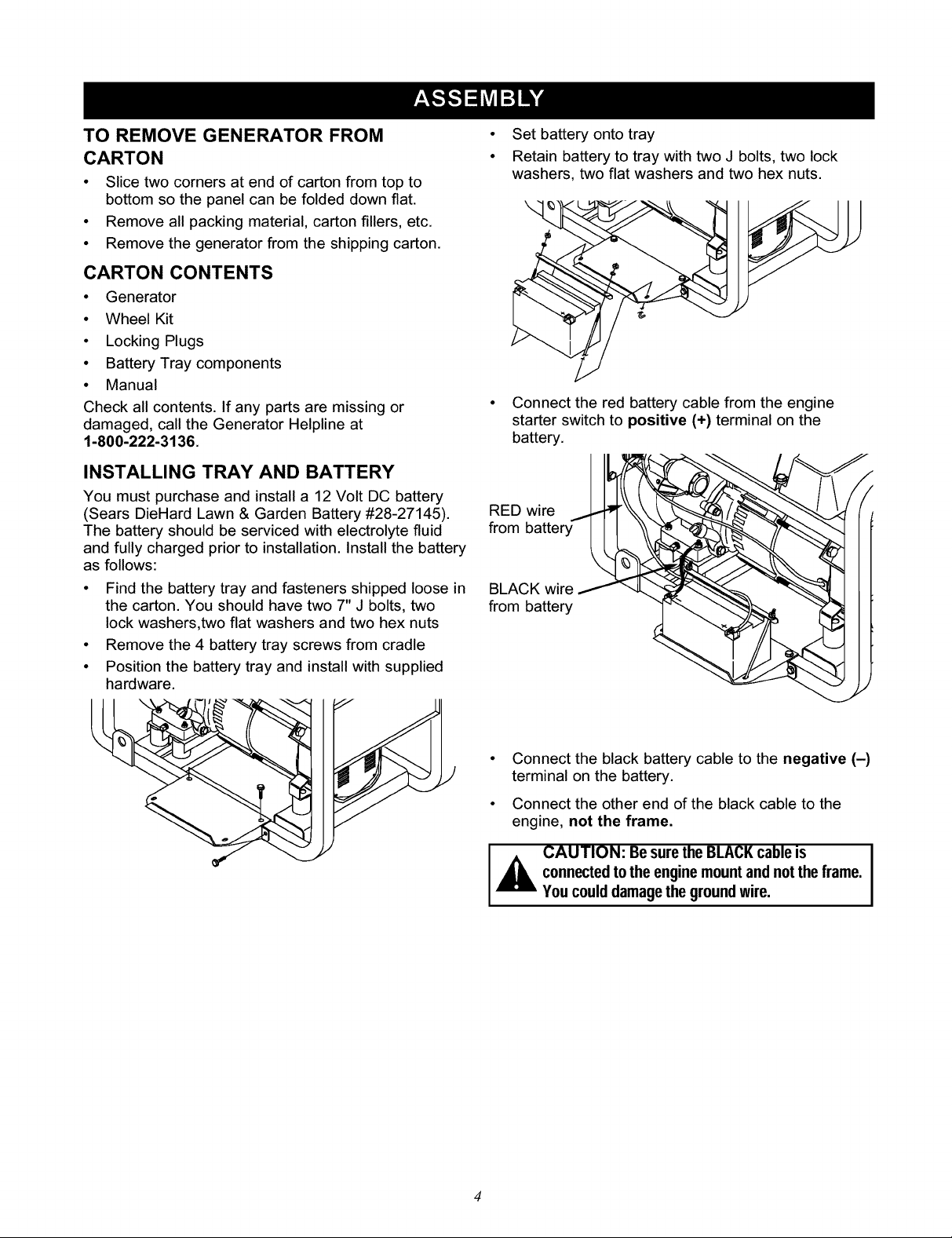
• Find the battery tray and fasteners shipped loose in
the carton. You should have two 7" J bolts, two
lock washers,two flat washers and two hex nuts
• Remove the 4 battery tray screws from cradle
• Position the battery tray and install with supplied
hardware.
• Set battery onto tray
• Retain battery to tray with two J bolts, two lock
washers, two flat washers and two hex nuts.
• Connect the red battery cable from the engine
starter switch to positive (+) terminal on the
battery.
RED bNi_ery'_
• Connect the black battery cable to the negative (-)
terminal on the battery.
• Connect the other end of the black cable to the
engine, not the frame.
I,_ AUTION: Be sure the BLACKcableis
connectedto the enginemountandnotthe frame.
You could damagethegroundwire.
Page 5
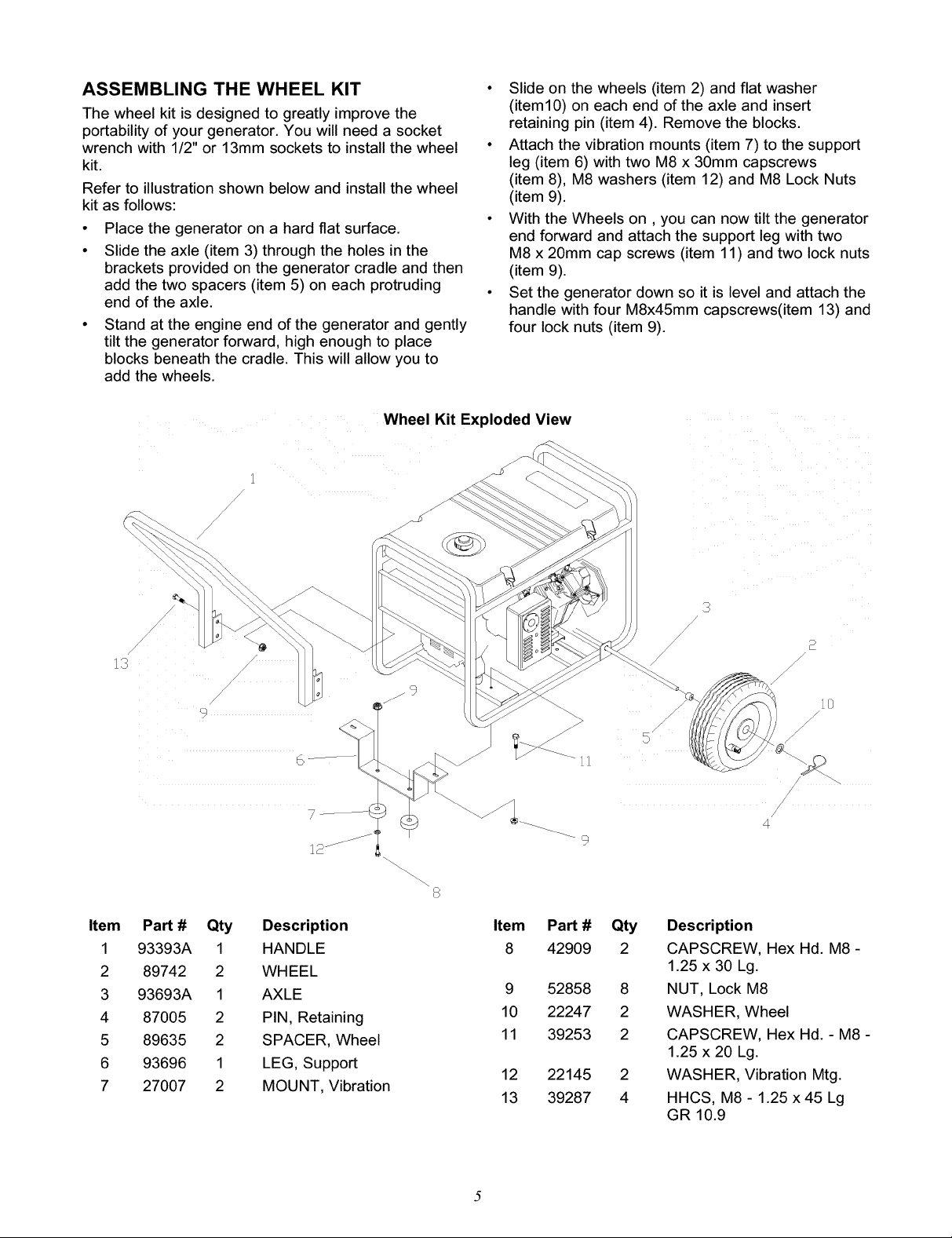
ASSEMBLING THE WHEEL KIT
The wheel kit is designed to greatly improve the
portability of your generator. You will need a socket
wrench with 1/2" or 13mm sockets to install the wheel
kit.
Refer to illustration shown below and install the wheel
kit as follows:
• Place the generator on a hard flat surface.
• Slide the axle (item 3) through the holes in the
brackets provided on the generator cradle and then
add the two spacers (item 5) on each protruding
end of the axle.
• Stand at the engine end of the generator and gently
tilt the generator forward, high enough to place
blocks beneath the cradle. This will allow you to
add the wheels.
Wheel Kit Exploded View
• Slide on the wheels (item 2) and flat washer
(item10) on each end of the axle and insert
retaining pin (item 4). Remove the blocks.
• Attach the vibration mounts (item 7) to the support
leg (item 6) with two M8 x 30mm capscrews
(item 8), M8 washers (item 12) and M8 Lock Nuts
(item 9).
• With the Wheels on, you can now tilt the generator
end forward and attach the support leg with two
M8 x 20mm cap screws (item 11) and two lock nuts
(item 9).
• Set the generator down so it is level and attach the
handle with four M8x45mm capscrews(item 13) and
four lock nuts (item 9).
Item
1
2
3
4
5
6
7
/
13
Pan # Qty
93393A 1
89742 2
93693A 1
87005 2
89635 2
93696 1
27007 2
/
/
/
9
6
Description
HANDLE
WHEEL
AXLE
PIN, Retaining
SPACER, Wheel
LEG, Support
MOUNT, Vibration
9
!
4
Item
Pan #
8
42909
Qty
2
Description
CAPSCREW, Hex Hd. M8 -
1.25 x 30 Lg.
9
10
11
52858
22247
39253
8
NUT, Lock M8
2
WASHER, Wheel
2
CAPSCREW, Hex Hd. - M8 -
1.25 x 20 Lg.
12
13
22145
39287
2
WASHER, Vibration Mtg.
4
HHCS, M8 - 1.25 x 45 Lg
GR 10.9
Page 6
CORD SETS AND CONNECTOR PLUGS
120 Volt Cord Sets
Use only high quality, well-insulated, extension cords
with the generator's 120 Volt type electrical
receptacles.
Each receptacle socket is protected against overload
by a single 20-Amp push-to-reset type of circuit
breaker. Use each receptacle to operate 120 Volts,
single phase 60 Hz, AC electrical loads requiring up to
2400 watts (2.4 kW) at 20 Amps of current.
Check the ratings of all extension cords before you
use them. Extension cord sets used should be rated
125 Volts at 20 AC Amps or greater for most electrical
devices. Some devices, however, may not require this
type of extension cord. Check the owner's manuals of
those devices for the manufacturer's
recommendations.
Keep extension cords as short as possible, preferably
less than 15 feet long, to prevent voltage drop and
possible overheating of wires.
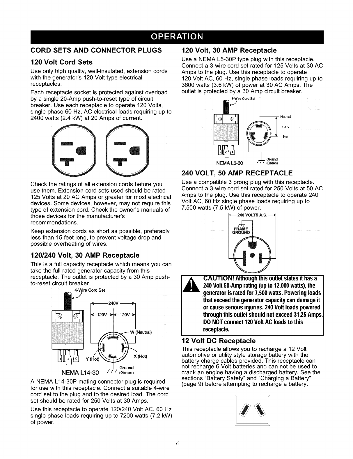
120 Volt, 30 AMP Receptacle
Use a NEMA L5-30P type plug with this receptacle.
Connect a 3-wire cord set rated for 125 Volts at 30 AC
Amps to the plug. Use this receptacle to operate
120 Volt AC, 60 Hz, single phase loads requiring up to
3600 watts (3.6 kW) of power at 30 AC Amps. The
outlet is protected by a 30 Amp circuit breaker.
3-Wira Cord Set
-- Neutral
120V
Hot
NEMA L5-30
240 VOLT, 50 AMP RECEPTACLE
Use a compatible 3 prong plug with this receptacle.
Connect a 3-wire cord set rated for 250 Volts at 50 AC
Amps to the plug. Use this receptacle to operate 240
Volt AC, 60 Hz single phase loads requiring up to
7,500 watts (7.5 kW) of power.
120/240 Volt, 30 AMP Receptacle
This is a full capacity receptacle which means you can
take the full rated generator capacity from this
receptacle. The outlet is protected by a 30 Amp push-
to-reset circuit breaker.
4-Wire Cord Set
240V
_- 120V_- 120V--_
Neutrai)
Y I P_ot)_ X (Hot)
NEMA L14-30 ,/-717 _rrOUenn_
A NEMA L14-30P mating connector plug is required
for use with this receptacle. Connect a suitable 4-wire
cord set to the plug and to the desired load. The cord
set should be rated for 250 Volts at 30 Amps.
Use this receptacle to operate 120/240 Volt AC, 60 Hz
single phase loads requiring up to 7200 watts (7.2 kW)
of power.
CAUTION! Althoughthis outlet states it has a
240 Volt50-Amprating(up to 12,000watts),the
generator is ratedfor 7,500watts. Powering loads
thatexceed thegeneratorcapacitycan damageit
or causeserious injuries.240Volt loadspowered
throughthis outletshould not exceed31.25Amps.
DO NOTconnect120 VoltAC loadstothis
receptacle.
2 Volt DC Receptacle
This receptacle allows you to recharge a 12 Volt
automotive or utilitystyle storage battery with the
battery charge cables provided. This receptacle can
not recharge 6 Volt batteries and can not be used to
crank an engine having a discharged battery. See the
sections "Battery Safety" and "Charging a Battery"
(page 9) before attempting to recharge a battery.
Page 7
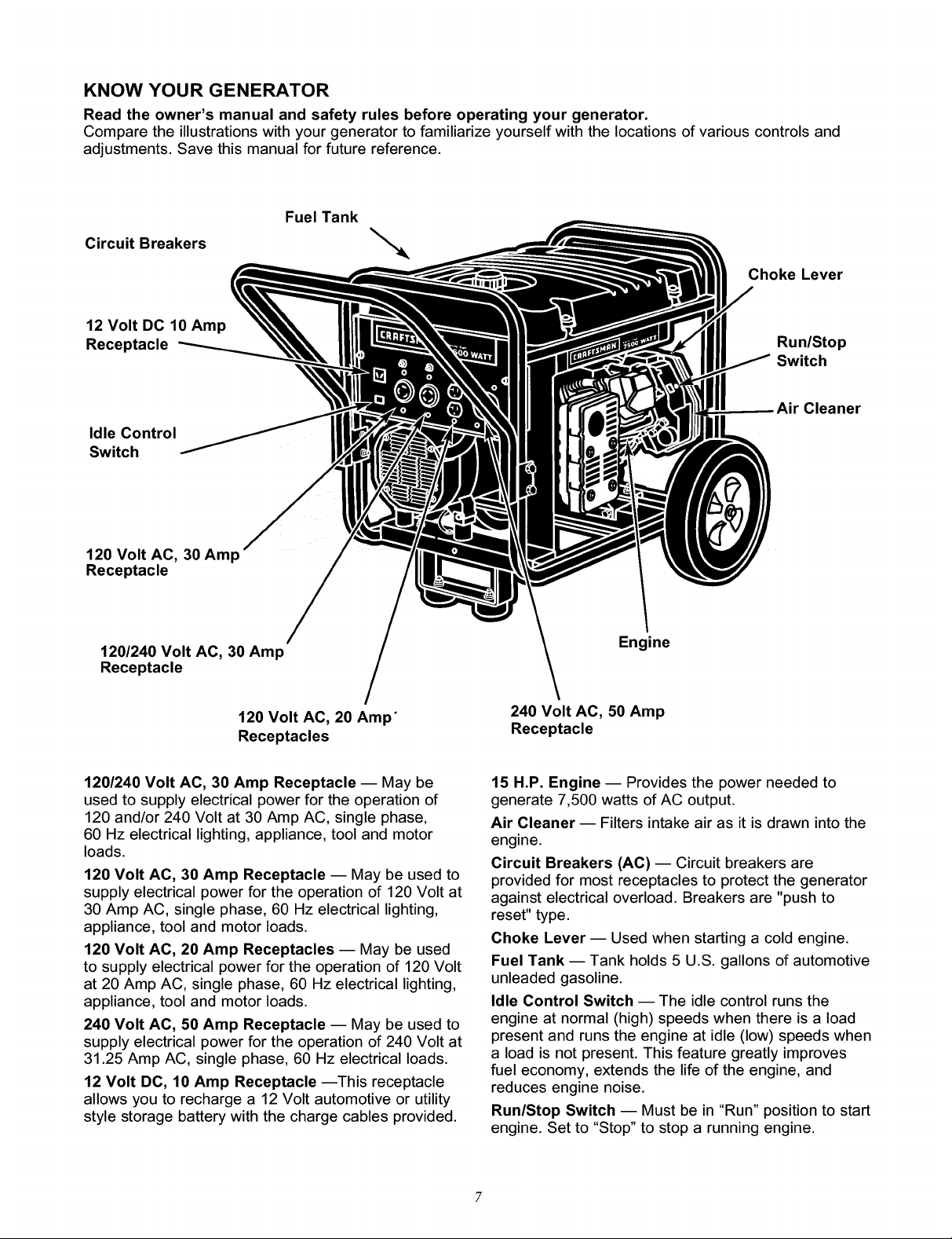
KNOW YOUR GENERATOR
Read the owner's manual and safety rules before operating your generator.
Compare the illustrations with your generator to familiarize yourself with the locations of various controls and
adjustments. Save this manual for future reference.
FuelTank
Circuit Breakers "_
Choke Lever
12 Volt DC 10 Amp
Receptacle
Idle Control
Switch
Run/Stop
Switch
Cleaner
120 Volt AC, 30 Amp
Receptacle
120/240 Volt AC, 30 Amp
Receptacle
120 Volt AC, 20 Amp"
Receptacles
120/240 Volt AC, 30 Amp Receptacle -- May be
used to supply electrical power for the operation of
120 and/or 240 Volt at 30 Amp AC, single phase,
60 Hz electrical lighting, appliance, tool and motor
loads.
120 Volt AC, 30 Amp Receptacle -- May be used to
supply electrical power for the operation of 120 Volt at
30 Amp AC, single phase, 60 Hz electrical lighting,
appliance, tool and motor loads.
120 Volt AC, 20 Amp Receptacles -- May be used
to supply electrical power for the operation of 120 Volt
at 20 Amp AC, single phase, 60 Hz electrical lighting,
appliance, tool and motor loads.
240 Volt AC, 50 Amp Receptacle -- May be used to
supply electrical power for the operation of 240 Volt at
31.25 Amp AC, single phase, 60 Hz electrical loads.
12 Volt DC, 10 Amp Receptacle --This receptacle
allows you to recharge a 12 Volt automotive or utility
style storage battery with the charge cables provided.
Engine
240 Volt AC, 50 Amp
Receptacle
15 H.P. Engine -- Provides the power needed to
generate 7,500 watts of AC output.
Air Cleaner -- Filters intake air as it is drawn into the
engine.
Circuit Breakers (AC) -- Circuit breakers are
provided for most receptacles to protect the generator
against electrical overload. Breakers are "push to
reset" type.
Choke Lever- Used when starting a cold engine.
Fuel Tank -- Tank holds 5 U.S. gallons of automotive
unleaded gasoline.
Idle Control Switch -- The idle control runs the
engine at normal (high) speeds when there is a load
present and runs the engine at idle (low) speeds when
a load is not present. This feature greatly improves
fuel economy, extends the life of the engine, and
reduces engine noise.
Run/Stop Switch -- Must be in "Run" position to start
engine. Set to "Stop" to stop a running engine.
Page 8
HOW TO USE YOUR GENERATOR
IF YOU HAVE ANY PROBLEMS operating your
generator, please call the generator helpline at
1-800-222-3136.
GROUNDING THE GENERATOR
The National Electrical Code requires that the frame
and external electrically conductive parts of this
generator be properly connected to an approved earth
ground. Local electrical codes may also require proper
grounding of the unit. For that purpose, a grounding
wing nut is provided on the base of the cradle.
Generally, connecting a No. 12 AWG (American Wire
Gauge) stranded copper wire to the grounding lug and
to an earth-driven copper or brass grounding rod
(electrode) provides adequate protection against
electrical shock. However, local codes may vary
widely. Consult with a local electrician for grounding
requirements in your area.
Proper grounding of generator will help prevent
electrical shock in the event of a ground fault condition
in the generator or in connected electrical devices.
Proper grounding also helps dissipate static electricity,
which often builds up in ungrounded devices.
CONNECTING ELECTRICAL LOADS
Let engine stabilize and warm up for a few minutes
after starting.
Do not connect 240 Volts to 120 Volt duplex
receptacles
Do not connect 3-phase loads to receptacles.
Plug in and turn on the desired 120 and/or 240
Volt, single phase, 60 Hertz, AC electrical loads.
DO NOT OVERLOAD THE GENERATOR. Add up
the rated watts (or Amps) of all loads to be
connected at one time. This total should not be
greater than the rated wattage/amperage capacity
of the generator. See Don't Overload the Generator
on Page 10.
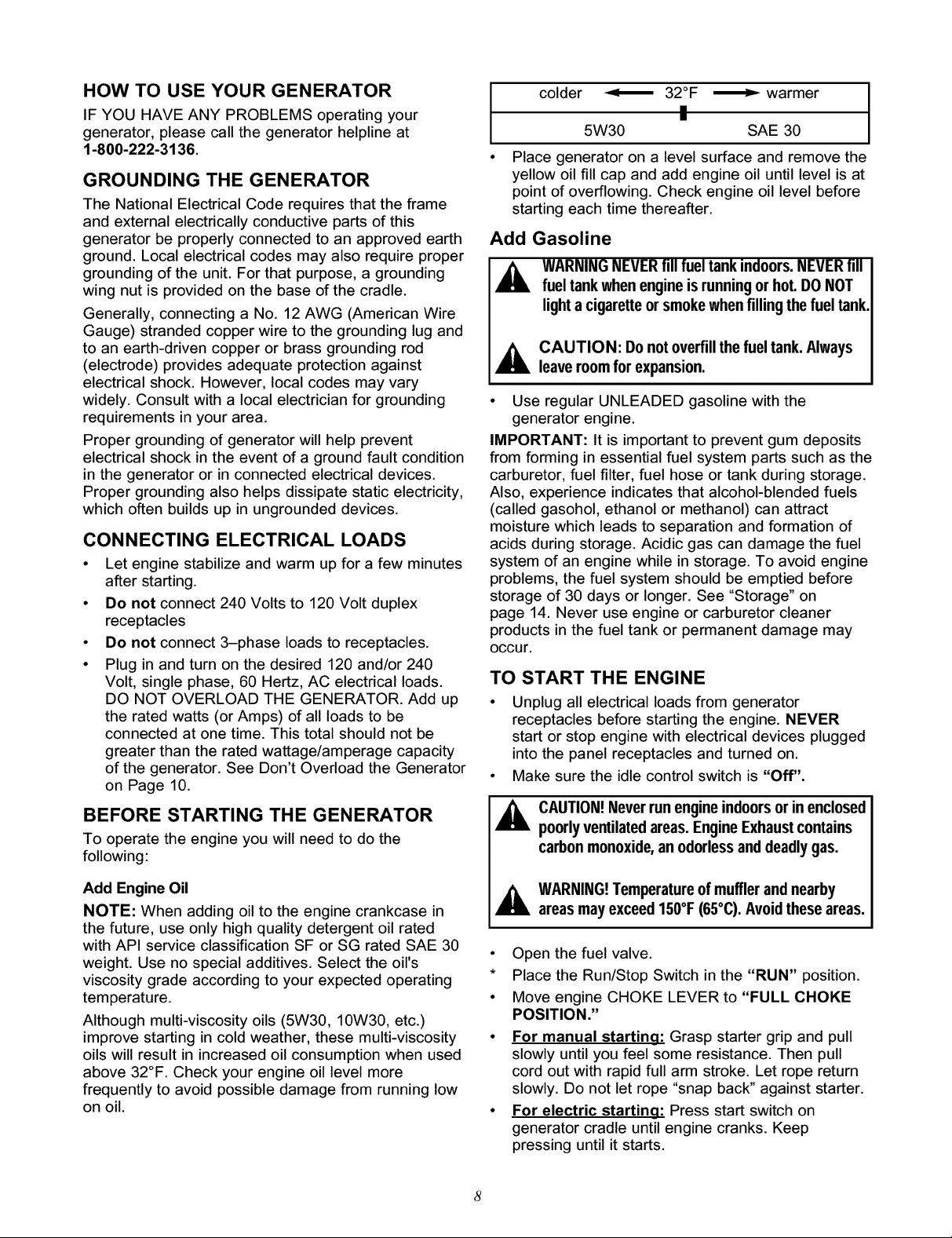
colder _ 32°F _ warmer
!
I
Place generator on a level surface and remove the
yellow oil fill cap and add engine oil until level is at
point of overflowing. Check engine oil level before
starting each time thereafter.
Add Gasoline
_ AUTION: Donotoverfillthefueltank.Always
• Use regular UNLEADED gasoline with the
generator engine.
IMPORTANT: It is important to prevent gum deposits
from forming in essential fuel system parts such as the
carburetor, fuel filter, fuel hose or tank during storage.
Also, experience indicates that alcohol-blended fuels
(called gasohol, ethanol or methanol) can attract
moisture which leads to separation and formation of
acids during storage. Acidic gas can damage the fuel
system of an engine while in storage. To avoid engine
problems, the fuel system should be emptied before
storage of 30 days or longer. See "Storage" on
page 14. Never use engine or carburetor cleaner
products in the fuel tank or permanent damage may
Occur.
TO START THE ENGINE
• Unplug all electrical loads from generator
receptacles before starting the engine. NEVER
start or stop engine with electrical devices plugged
into the panel receptacles and turned on.
• Make sure the idle control switch is "Off".
5W30 SAE 30
WARNINGNEVERfill fuel tank indoors.NEVERfill
fuel tank when engineisrunningor hot.DO NOT
lighta cigaretteor smokewhen filling the fuel tank.
leaveroomfor expansion.
BEFORE STARTING THE GENERATOR
To operate the engine you will need to do the
following:
Add Engine Oil
NOTE: When adding oil to the engine crankcase in
the future, use only high quality detergent oil rated
with API service classification SF or SG rated SAE 30
weight. Use no special additives. Select the oil's
viscosity grade according to your expected operating
temperature.
Although multi-viscosity oils (5W30, 10W30, etc.)
improve starting in cold weather, these multi-viscosity
oils will result in increased oil consumption when used
above 32°F. Check your engine oil level more
frequently to avoid possible damage from running low
on oil.
_ AUTION!Never runengineindoorsor in enclosed
poorlyventilatedareas. EngineExhaustcontains
carbonmonoxide,an odorlessanddeadlygas.
,_ WARNING!Temperatureof mufflerand nearby
areasmay exceed 150°F(65°C).Avoidtheseareas.
• Open the fuel valve.
* Place the Run/Stop Switch in the "RUN" position.
• Move engine CHOKE LEVER to "FULL CHOKE
POSITION."
• For manual starting: Grasp starter grip and pull
slowly until you feel some resistance. Then pull
cord out with rapid full arm stroke. Let rope return
slowly. Do not let rope "snap back" against starter.
• For electric starting: Press start switch on
generator cradle until engine cranks. Keep
pressing until it starts.
Page 9
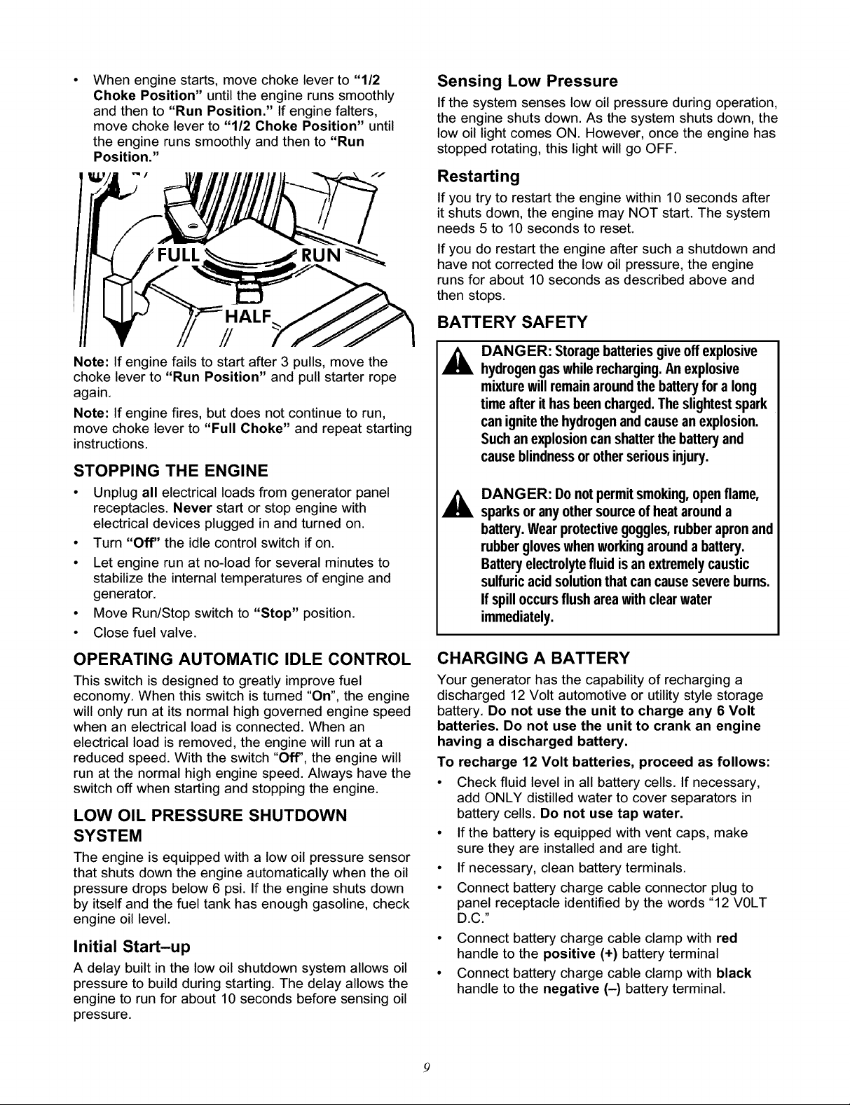
Whenenginestarts,movechokeleverto"1/2
ChokePosition"untiltheenginerunssmoothly
andthento"RunPosition."Ifenginefalters,
movechokeleverto"1/2ChokePosition"until
theenginerunssmoothlyandthento"Run
Position."
FULL RUN
HALF
//
Note: If engine fails to start after 3 pulls, move the
choke lever to "Run Position" and pull starter rope
again.
Note: If engine fires, but does not continue to run,
move choke lever to "Full Choke" and repeat starting
instructions.
STOPPING THE ENGINE
• Unplug all electrical loads from generator panel
receptacles. Never start or stop engine with
electrical devices plugged inand turned on.
• Turn "Off" the idle control switch if on.
• Let engine run at no-load for several minutes to
stabilize the internal temperatures of engine and
generator.
• Move Run/Stop switch to "Stop" position.
• Close fuel valve.
Sensing Low Pressure
If the system senses low oil pressure during operation,
the engine shuts down. As the system shuts down, the
low oil light comes ON. However, once the engine has
stopped rotating, this light will go OFF.
Restarting
If you try to restart the engine within 10 seconds after
it shuts down, the engine may NOT start. The system
needs 5 to 10 seconds to reset.
If you do restart the engine after such a shutdown and
have not corrected the low oil pressure, the engine
runs for about 10 seconds as described above and
then stops.
BATTERY SAFETY
DANGER: Storagebatteriesgive offexplosive
hydrogengas while recharging.Anexplosive
mixturewill remainaroundthe batteryfor a long
timeafter it has beencharged.The slightestspark
canignitethe hydrogenand causean explosion.
Suchan explosioncan shatterthe batteryand
causeblindnessor other seriousinjury.
DANGER: Donotpermitsmoking,openflame,
sparksoranyothersourceofheatarounda
battery.Wearprotectivegoggles,rubberapronand
rubbergloveswhenworkingaroundabattery.
Batteryelectrolytefluid isanextremelycaustic
sulfuricacidsolutionthatcancausesevereburns.
Ifspilloccursflushareawithclearwater
immediately.
OPERATING AUTOMATIC IDLE CONTROL
This switch is designed to greatly improve fuel
economy. When this switch is turned "On", the engine
will only run at its normal high governed engine speed
when an electrical load is connected. When an
electrical load is removed, the engine will run at a
reduced speed. With the switch "Off", the engine will
run at the normal high engine speed. Always have the
switch off when starting and stopping the engine.
LOW OIL PRESSURE SHUTDOWN
SYSTEM
The engine is equipped with a low oil pressure sensor
that shuts down the engine automatically when the oil
pressure drops below 6 psi. If the engine shuts down
by itself and the fuel tank has enough gasoline, check
engine oil level.
Initial Start-up
A delay built in the low oil shutdown system allows oil
pressure to build during starting. The delay allows the
engine to run for about 10 seconds before sensing oil
pressure.
CHARGING A BATTERY
Your generator has the capability of recharging a
discharged 12 Volt automotive or utility style storage
battery. Do not use the unit to charge any 6 Volt
batteries. Do not use the unit to crank an engine
having a discharged battery.
To recharge 12 Volt batteries, proceed as follows:
• Check fluid level in all battery cells. If necessary,
add ONLY distilled water to cover separators in
battery cells. Do not use tap water.
• If the battery is equipped with vent caps, make
sure they are installed and are tight.
• If necessary, clean battery terminals.
• Connect battery charge cable connector plug to
panel receptacle identified by the words "12 VOLT
D.C."
• Connect battery charge cable clamp with red
handle to the positive (+) battery terminal
• Connect battery charge cable clamp with black
handle to the negative (-) battery terminal.
Page 10

• Startengine.Lettheenginerunwhilebattery
recharges.
• Whenbatteryhascharged,shutdownengine
NOTE:Useanautomotivehydrometertotestbattery
stateofchargeandcondition.Followthehydrometer
manufacturer'sinstructionscarefully.Generally,a
batteryisconsideredto beat100%stateofcharge
whenspecificgravityofitsfluid(asmeasuredby
hydrometer)is1.260orhigher.
DON'T OVERLOAD THE GENERATOR
Overloading a generator in excess of its rated wattage
capacity can result in damage to the generator and to
connected electrical devices. Observe the following, to
prevent overloading the unit:
• Add up the total wattage of all electrical devices to
be connected at one time. This total should NOT be
greater than the generator's wattage capacity.
WATTAGE REFERENCE GUIDE
RUNNING
WATTS
*Air Conditioner (12,000 Btu) ........................................ 1700
Battery Charger (20 Amp) ............................................... 500
Belt Sander (3") ............................................................. 1000
Chain Saw ..................................................................... 1200
Circular Saw (6-1/2") .......................................... 800 to 1000
Coffee Maker ................................................................. 1000
*Compressor (1 HP) ...................................................... 2000
*Compressor (3/4 HP) ................................................... 1800
*Compressor (1/2 HP) ................................................... 1400
Curling Iron ...................................................................... 700
*Freezer .......................................................................... 500
Disc Sander (9") ............................................................ 1200
Edge Trimmer ................................................................. 500
Electric Nail Gun ........................................................... 1200
Electric Range (one element) ....................................... 1500
Electric Skillet ................................................................ 1250
*Furnace Fan (1/3 HP) .................................................. 1200
Hair Dryer ...................................................................... 1200
Hand Drill (1") ................................................................ 1100
Hand Drill (1/2") ................................................. 750 to 1000
Hand Drill (3/8") ............................................................... 500
Hand Drill (1/4") ............................................................... 250
Hedge Trimmer ............................................................... 450
The rated wattage of lights can be taken from light
bulbs. The rated wattage of tools, appliances and
motors can usually be found on a data plate or
decal affixed to the device.
If the appliance, tool or motor does not give
wattage, multiply volts times ampere rating to
determine watts (volts x amps = watts).
Some electric motors, such as induction types,
require about three times more watts of power for
starting than for running. This surge of power lasts
only a few seconds when starting such motors.
Make sure you allow for this high starting wattage
when selecting electrical devices to connect to your
generator. First, figure the watts needed to start the
largest motor. Add to that figure the running watts
of all other connected loads.
The Wattage Reference Guide below is provided to
assist you in determining how many items your
generator can operate at one time.
RUNNING
WATTS
Impact Wrench ................................................................ 500
*Jet Pump ........................................................................ 800
Lawn Mower .................................................................. 1200
Light Bulb ........................................................................ 100
Microwave Oven ............................................................. 700
*Milk Cooler ................................................................... 1100
Oil Burner on Furnace ..................................................... 300
Oil Fired Space Heater (140,000 Btu) ............................ 400
Oil Fired Space Heater (85,000 Btu) .............................. 225
Oil Fired Space Heater (30,000 Btu) .............................. 150
*Paint Sprayer, Airless (1/3 HP) ..................................... 600
Paint Sprayer, Airless (handheld) ................................... 150
Radio ...................................................................... 50 to 200
*Refrigerator .................................................................... 600
Slow Cooker .................................................................... 200
*Submersible Pump (1-1/2 HP) ..................................... 2800
*Submersible Pump (1 HP) ........................................... 2000
*Submersible Pump (1/2 HP)........................................ 1500
Sump Pump ................................................................... 600
*Table Saw (10") .............................................. 1750 to 2000
Television ............................................................. 200 to 500
Weed Trimmer ................................................................ 500
* Allow 3 times the listed watts for starting these devices.
/0
Page 11

MAINTENANCE SCHEDULE
Follow the hourly or calendar intervals, whichever occurs first.
More frequent service is required when operating in adverse conditions noted below.
Maintenance Operation
Check oil level
Change oil and oil filter-J:
Clean Spark Arrestor Screen
Service air cleaner
Service air cleaner cartridge
Adjust Valve Clearance
Replace spark plugs
Retorque head bolts
Every 8 Hours 25 Hours or 50 Hours or 100 Hours or Yearly
or Daily Every Season Every Season Every Season
X
Change oil after first 8 hours of operation then after every 50 hours or every season.
* Change oil and oil filter every 25 hours when operating under heavy load or in high
temperatures.
** Clean more often under dirty or dusty conditions. Replace Cleaner parts if very dirty.
*** Perform this task only after first 50 hours of operation. Head bolts will not need further
re-torquing.
PRODUCT SPECIFICATIONS
Generator Specifications
Rated Maximum Power ........ 7500 Watts (7.5kW)
Rated Voltage ............... 120/240 Volts AC
Rated Maximum Current
at 240 Volts ................ 31.2 AC Amperes
Rated Maximum Current
at 120 Volts ................ 62.5 AC Amperes
Rated Frequency ............ 60 Hz at 3600 rpm
Phase ..................... Single Phase
Engine Specifications
Rated Horsepower ........... 15 at 3600 rpm
Displacement ............... 410 cc
Spark Plug
Type: ................ Champion RC12YC or
Equivalent
Set Gap To: ........... 0.030inch (0.76mm)
Gasoline Capacity ............ 5 U.S. gallons
Oil
Summer ............. SAE 30 (10W-30)
Winter .............. SAE 5W-20 or 5W-30
GENERAL RECOMMENDATIONS
The warranty of the generator does not cover items
that have been subjected to operator abuse or
negligence. To receive full value from the warranty,
operator must maintain generator as instructed in this
manual.
Some adjustments will need to be made periodically to
properly maintain your generator.
All adjustments in the Service and Adjustments
section of this manual should be made at least once
each season. Follow the requirements in the
"Maintenance Schedule" chart above.
Note: Once a year you should clean or replace the
spark plug and replace the air filter. A new spark plug
and clean air filter assure proper fuel-air mixture and
help your engine run better and last longer.
GENERATOR MAINTENANCE
Generator maintenance consists of keeping the unit
clean and dry. Operate and store the unit in a clean
dry environment where it will not be exposed to
excessive dust, dirt, moisture or any corrosive vapors.
Cooling air slots in the generator must not become
clogged with snow, leaves,or any other foreign
material.
Check the cleanliness of the generator frequently and
clean when dust, dirt, oil, moisture or other foreign
substances are visible on its exterior surface.
Note: We DO NOT recommend using a garden hose
to clean generator. Water can enter the engine fuel
system and cause problems. In addition, if water
enters the generator through cooling air slots, some of
the water will be retained in voids and cracks of the
rotor and stator winding insulation. Water and dirt
buildup on the generator internal windings will
eventually decrease the insulation resistance of these
windings.
/1
Page 12

TO CLEAN THE GENERATOR:
IA CAUTION: Never Insertany objector tool
• Use a damp cloth to wipe exterior surfaces clean.
• A soft, bristle brush may be used to loosen caked
• A vacuum cleaner may be used to pick up loose
• Low pressure air (not to exceed 25 psi) may be
throughtheair coolingslots,even if theengine is
not running,
on dirt, oil, etc.
dirt and debris.
used to blow away dirt. Inspect cooling air slots
and openings on the generator. These openings
must be kept clean and unobstructed.
ENGINE MAINTENANCE
A ANGER: Whenworkingonthegenerator
alwaysdisconnectsparkplugwirefromsparkplug
andkeepitawayfromsparkplug.
CHECKING OIL LEVEL
Oil level should be checked prior to each use or at
least every 8 hours of operation. Keep oil level
maintained.
CHANGING ENGINE OIL AND OIL FILTER
Change oil after first 8 hours of operation. Change oil
and oil filter every 50 hours thereafter. If you are using
your generator under extremely dirty or dusty
conditions, or in extremely hot weather, change oil
more often.
Change oil while engine is still warm from running, as
follows:
• Clean area around oil drain plug.
• Remove oil drain plug and oil fill plug and drain oil
completely into a suitable container.
• When oil has completely drained, Install oil drain
plug and tighten securely.
• Place a suitable container beneath the oil filter and
turn filter counterclockwise to remove. Discard
according to local regulations.
• Coat gasket of new filter (p/n 70185) with engine
oil. turn filter clockwise until gasket contacts tightly
with filter adapter. Then tighten an additional 3/4
turn.
• Fill oil sump with recommended oil. (See "Before
Starting the Engine" on page 8 for oil
recommendations)
• Install the oil fill plug and tighten securely.
• Wipe up any spilled oil.
• Clean area around spark plug.
• Remove and inspect spark plug.
• Replace spark plug if electrodes are pitted, burned
or porcelain is cracked. For Replacement use
Champion RC12YC or equivalent.
• Check electrode gap with wire feeler gauge and set
spark plug gap to 0.030 inch (0.76mm) if
necessary.
RETORQUE HEAD BOLTS
After the first 50 hours of operation, you must retorque
the head bolts 6.9 kg.-m. (44 ft.-Ibs.)
Important: If you feel uncomfortable about doing this
procedure or you don't have the proper tools, please
take your generator in to the nearest service center to
have the head bolts re-torqued. This is a very
important step to insure the longest life for your
engine.
NOTE: Only perform this adjustment after the first 50
hours of operation. The head bolts will need no further
adjustment.
• Torque sequence is as follows: A, B, C, D,
(alternating pattern).
A
g
SERVICE AIR CLEANER
Your engine will not run properly and may be
damaged if you run it using a dirty air cleaner. Clean
or replace the air cleaner paper filter once every 50
hours of operation or once a year, whichever comes
first. Clean or replace more often if operating under
dusty conditions. Clean foam pre-cleaner every 25
hours of operation or sooner under dusty conditions.
PAPER
FILTER
CLEAN/REPLACE SPARK PLUG
Change the spark plug every 100 hours of operation
or once each year, whichever comes first. This will
help your engine to start easier and run better.
Replace with Champion RC12YC or equivalent.
FOAM
/2
PRE-FILTER
Page 13

To clean or replace foam pre-cleaner:
• Remove air cleaner cover, then foam pre-filter.
• Wash pre-cleaner in soapy water. Squeeze pre-
filter dry in clean cloth (DO NOT TWIST).
• Clean air cleaner cover before installing it.
To clean or replace paper air filter:
• Remove air cleaner cover; then remove foam pre-
filter (service if necessary) and remove paper filter.
• Clean paper filter by tapping it gently on a solid
surface. If the filter istoo dirty, replace it with a new
one. Dispose of the old filter properly.
• Clean air cleaner cover then insert pre-cleaner into
cover. Next insert new paper filter into cover to hold
pre-cleaner in place and assemble all of them to
the base of the air cleaner.
Note: If you need to order a new air filter, please call
1-800-366-PART.
CLEAN SPARK ARRESTOR SCREEN
The engine exhaust muffler has a spark arrestor
screen. Inspect and clean the screen every 100 hours
of operation or once each year, whichever comes first.
NOTE: If you use your generator on any forest-
covered, brush-covered or grass-covered unimproved
land, it must have a spark arrestor. The spark arrestor
must be maintained in good condition by the
owner/operator.
Clean and inspect the spark arrestor as follows:
• To remove the muffler guard from the muffler,
remove the four screws that connect the guard to
the muffler bracket.
SPARKARRESTER
SCREEN
MUFFLER
HEAT SHIELD
To adjusting valve clearance:
• Make sure the engine is at room temperature
• Make sure that the spark plug wire is removed from
the spark plug and out of the way.
Remove the breather tube from the valve cover.
Remove the four screws attaching the valve cover
with a #2 or 3 phillips screwdriver.
Make sure the piston is at Top Dead Center (TDC)
of its compression stroke (both valves closed). To
get the piston at top dead center, pull on the recoil
handle slowly watching the piston trough the spark
plug hole. As you pull on the recoil handle the
piston should move up and down. The piston is put
Top Dead Center when it is up as high as it can go.
Feeler
Allen Wrench Gauge
Loosen
Jam Nut
• Loosen the rocker arm jam nut. Use an 8mm allen
wrench to turn the pivot ball stud while checking
clearance between the rocker arm and the valve
stem with a feeler gauge. Correct clearance is
0.002-0.004 inch (0.05-0.1mm). Note: You must
hold the rocker arm jam nut in place as you turn the
pivot ball stud.
• When valve clearance is correct, hold the pivot ball
stud in place with the allen wrench and tighten the
rocker arm jam nut. Tighten the jam nut to 165-183
inch-pounds torque. After tightening the jam nut,
recheck valve clearance to make sure it did not
change.
Remove four screws that attach the spark arrestor
screen.
Inspect screen and replace if torn, perforated or
otherwise damaged. DO NOT USE a defective
screen. If screen is not damaged, clean it with
commercial solvent.
Reattach the screen and the muffler guard.
ADJUSTING VALVE CLEARANCE
After the first 50 hours of operation, you should adjust
the valve clearance inthe engine.
Important: If you feel uncomfortable about doing this
procedure or you don't have the proper tools, please
take your generator in to the nearest service center to
have the valve clearance adjusted. This is a very
important step to insure longest life for your engine.
Tighten Jam Nut to 165
inch-pounds - 183
inch-pounds (19-21 N-m)
Reattach the valve cover. Note: Start all four
screws before tightening or you will not be able to
get all the screws in place. Note: Make sure the
gasket between the valve cover and cylinder head
is in place.
Reattach the breather tube.
Reattach the spark plug wire to the spark plug.
/3
Page 14

GENERAL
The generator should be started at least once every
seven days and allowed to run at least 30 minutes. If
this cannot be done and you must store the unit for
more than 30 days, use the following information as a
guide to prepare it for storage.
indoorsorinenclosed,poorlyventilatedareaswhere
fumesmayreachanopenflame,sparkorpilotlight
asona furnace,waterheater,clothesdryerorother
I_, WARNING: NEVERstoreenginewithfuelintank
gasappliance.
LONG TERM STORAGE INSTRUCTIONS
It is important to prevent gum deposits from forming in
essential fuel system parts such as the carburetor, fuel
filter, fuel hose or tank during storage. Also,
experience indicates that alcohol-blended fuels (called
gasohol, ethanol or methanol) can attract moisture
which leads to separation and formation of acids
during storage. Acidic gas can damage the fuel
system of an engine while in storage.
To avoid engine problems, the fuel system should be
emptied before storage of 30 days or longer. Follow
these instructions:
outdoors,awayfromopen flame. Besureengineis
I_ WARNING:Drainfuel intoapprovedcontainer
cool.Do not smoke.
Protect Fuel System
• Remove all gasoline from the fuel tank to prevent
gum deposits from forming on these parts and
causing possible malfunction of engine.
• Run engine until engine stops from lack of fuel.
Change Oil
While engine is still warm, drain oil from crankcase.
Refill with recommended grade.
Oil Cylinder Bore
I_, CAUTION! Avoid sprayfromsparkplugholewhencrankingengineslowly.
• Remove spark plug and pour about 1/2 ounce
(15ml) of engine oil into the cylinder. Cover spark
plug hole with rag. Crank slowly to distribute oil.
• Install spark plug. Do not connect spark plug wire.
GENERATOR:
• Clean the generator as outlined on Page 11 ("To
Clean the Generator").
• Check that cooling air slots and openings on
generator are open and unobstructed.
OTHER STORAGE TIPS:
• Do not store gasoline from one season to another.
• Replace your gasoline can if your can starts to rust.
Rust and/or dirt in your gasoline will cause
problems.
• If possible, store your unit indoors and cover it to
give protection from dust and dirt. BE SURE TO
EMPTY THE FUEL TANK.
• Cover your unit with a suitable protective cover that
does not retain moisture.
• Store generator in clean, dry area.
IMPORTANT: NEVER cover your generator while
engine and exhaust area are warm.
14
Page 15

Problem
Engineisrunning,butno
ACoutputisavailable.
Cause
1.Oneof thecircuitbreakersisopen.
2.Faultin generator.
3.Poorconnectionordefective
cordset.
4. Connecteddeviceis bad.
Correction
1.Resetcircuitbreaker.
2.ContactSearsServiceFacility.
3.Checkandrepair.
4.Connectanotherdevicethat
isin goodcondition.
Enginerunsgoodat no-loadbut"bogs
down"whenloadsare connected
Enginewillnotstart;or starts
andrunsrough.
Engineshutsdownduringoperation
Enginelackspower.
1.Shortcircuitin a connectedload.
2.Enginespeedistoo slow.
3.Generatorisoverloaded.
4. Shortedgeneratorcircuit.
1.Run/StopSwitchsetto STOP.
2.Dirtyair cleaner
3.Out ofgasoline.
4. Stalegasoline.
5.Sparkplugwirenotconnected
tosparkplug.
6. Badsparkplug.
7. Waterin gasoline.
8. Overchoking.
9. Lowoil level 9.
10.Excessivelyrichfuelmixture.
11.Intakevalvestuckopenorclosed.
12.Enginehaslostcompression.
1.Out ofgasoline.
2.Lowoil level.
1.Loadistoo high.
2.Dirtyairfilter.
1.Disconnectshortedelectrical
load.
2.ContactSearsServiceFacility.
3.See"Don'tOverloadthe
Generator"
4.ContactSearsServiceFacility.
1.Setswitchto RUN.
2.Cleanor replaceaircleaner.
3.Fillfueltank.
4.Draingastank;fillwith freshfuel.
5.Connectwiretosparkplug.
6.Replacesparkplug.
7.Draingastank;fillwith freshfuel.
8.Openchokefullyandcrankengine.
Fillcrankcaseto properlevel.
10. ContactSearsServiceFacility.
11. ContactSearsServiceFacility.
12. ContactSearsServiceFacility.
1.Fillfueltank.
2.Fillcrankcaseto properlevel.
1.See"Don'tOverloadthe Generator"
2.Replaceairfilter.
Engine"hunts"orfalters.
NobatterychargeDCoutput
1.Chokeis openedtoosoon.
2.Carburetorisrunningtoorich
ortoo lean.
1.Batterypostsarecorroded.
2.Batteryfluidlevel islow.
3.Batterycableis bad.
4. Batteryisdefective.
5.Receptacleisbad.
15
1.Movechoketo halfwaypositionuntil
enginerunssmoothly.
2.ContactSearsServiceFacility.
1.Cleanbatteryposts
2.Adddistilledwaterto battery.
3.Replacecable.
4.Checkbatterycondition;replaceif
defective.
5.ContactSearsServiceFacility.
Page 16

16
Page 17

ill
CRAFTSMAN 7500 Watt AC Generator 580.327181
Wiring Diagram
1
1
17
Page 18

CRAFTSMAN 7500 Watt AC Generator 580.327181
Main Unit -- Exploded View
7O
51
66
65 67
DETAIL OF ELECTRIC
START SWITCH
J
TO + TERMINAL
ON BA]WERY
10
900.
TO STARTER
51
21
22
5O
72 \
27
'\
\
\
29
2O
9
58
17
/
/
7O
55
I
55
18
Page 19

CRAFTSMAN 7500 Watt AC Generator 580.327181
Main Unit -- Parts List
ITEM PART #. QTY.
1 92432 1
2 92531 1
3 92731 1
4 92247 1
5 B1342G 1
6 B1897G 1
7 65791 1
8 96796 1
9 22129 12
10 86307 4
11 47481 1
12 92609 2
13 82857 2
14 40976 2
15 66476 2
16 92532 1
17 22142 2
18 91153 1
19 90239 1
20 81917 1
21 81887J 1
22 52618 2
23 52856 2
25 66825C 1
26 74908 4
27 66449L 4
28 65795 2
29 66849C 1
30 67022 1
31 84132 1
32 66386 1
33 66849 2
34 78388 1
35 22769 1
36 86494 1
37 86292 1
38 77395 4
39 83465 4
40 78831B 4
41 80270 1
42 78299 1
43 94834 1
44 93595 1
45 92039 1
46 92665 1
DESCRIPTION
CRADLE
SUPPORT, Engine 48
SUPPORT, Engine & Muffler 49
HOUSING, Engine Adapter 50
ASSEMBLY, Rotor 51
ASSEMBLY, Stator 52
BEARING 53
WASHER, Special M8 Flat 55
WASHER, M8 Lock 57
HHMS, 5/16 - 24 x 3/4 Lg. Sems 58
HHCS, 5/16 - 24 x 10 - 5/8 Lg. 60
MOUNT, Vibration 62
MOUNT, Vibration
SCREW, M8 - 1.25 x 20mm
CAPSCREW, M6 - 1.0 x 12mm
BRACKET, Muffler
SCREW, 5/16 - 18 x 3/4"
MUFFLER
GASKET, Muffler
PIN, 4 mm x 10 Roll
WRAP, Stator
HHCS, M5 - 0.8 x12 Lg.
NUT, M5 Locking
CARRIER, Rear Bearing
TAPTITE, M5 - 0.8 x 10 Lg.
BOLT, M6 - 1 x 190 mm Stator
RECTIFIER, Battery Charge
TAPTITE, M5 - 0.8 x 30 Lg.
GROMMET, Rubber
ASSEMBLY, Power Regulator
ASSEMBLY, Brush Holder
TAPTITE, M5 - 0.8 x 16 Lg.
COVER, Bearing Carrier
WASHER, Shakeproof Int. #10
SCREW, M6 - 1.0 x 16 Lg. Wing
HHCS, #10 Self Driller
NUT, M6 Flange Lock
GROMMET, Tank
HHMS, M6 - 1.0 x 60 Black 96923 1 Battery Tray
VALVE, Tank
BUSHING, Plastic Tank 45771 2 Hex Nut
CAP, Fuel Gauge 96925 1 Battery Tie-down
TANK, Fuel 96924 2 J-Bolt
SHIELD, Heat 154-53621 1 Battery Cable Positive
INSULATION, #2 -1/4" Thick 155-53621 1 Battery Cable Negative
ITEM PART #. QTY. DESCRIPTION
47 85000 1 CLIP, Insulation
143-53621 1 WIRE, Ground
26850 2 LW, EXT, M6 Shakeproof
57593 1 MOUNT, Cable Tie
92982 1 DECAL, Danger
B1899 2 DECAL, Heat Shield
B4901 1 DECAL, 1-800-4MyHome
25244 12 NUT, Hex 5/16 - 18
B1898 1 DECAL, Control Panel
B1332A
22531
93826
63 77282 1 SWITCH, Starter
64 22287 2 SCREW, 1/4 - 20" x 3/4"
65 22097 2 WASHER, M6 Lock
66 22127 2 NUT, 1/4 - 20" Hex
67 77283 1 ASSY, Starter Switch
68 96068 1 SHIELD, Heat
69 56893 5 CRIMPTITE, 10 - 24 x 1/2
70 B2153
71 23762
72 22097
900 NSP
Parts Not Illustrated
B1901
AB3061
37806
43438
65787
84882
Optional Accessories Not Illustrated
09-32688 Cord Wrap Kit
09-32687 120V 30A Locking Plug
Battery Tray Kit Not Illustrated
22129 2 Lockwasher
22145 2 Flat Washer
1 ASSEMBLY, Control Box
2 HHCS, 5/16 - 18 x 1-3/4" Lg.
1 DECAL, Start Instructions
8 HHCS, 12 - 14 x 7/8 Self Driller
1 SHAKEPROOF, Ext #10
4 LOCKWASHER, 1/4 - M6
1 ENGINE, 15 HP, Generac Power
Systems, EHF 00935
1 Owner's Manual
2 28oz. Engine Oil
1 120V 30A Locking Plug
1 120/240V 30 A Locking Plug
1 Battery Charge Cables
1 Spark Plug Wrench/Driver
19
Page 20

CRAFTSMAN 7500 Watt AC Generator 580.327181
Control Panel -- Exploded View and Parts List
21
2O
19
\
10
6
10
11
13
17 18
16 /
I
11
_0
8
19
7
18 8
8
25
25
31
\
5
52
27
ITEM PART# QTY.
1 B1331 1
2 23897 4
3 49226 4
4 91526 4
5 82538 1
6 82881 4
7 43181 4
8 43182 4
10 75207A 2
11 75207 2
12 23365 10
13 68868 1
14 43437 1
15 68759 1
16 43180 10
I
17
16
DESCRIPTION ITEM PART # QTY.
PANEL, Control 17 22264 10
WASHER, #10 M5 Flat 18 51715 10
WASHER, M5 Lock 19 64526 8
SCREW, M5-0.8 x 12 mm 20 83970 1
SWITCH, Idle Control 21 64525 4
WASHER, 7/16" Int. Lock 22 87962 1
SCREW, M3- 0.5 x 10 mm
WASHER, M3 Lock 23 84335 1
CIRCUIT BREAKER, 30 AMP 24 84134 1
CIRCUIT BREAKER, 20 AMP 25 92069 1
WASHER, #8 Shakeproof 26 84028 1
OUTLET, 30A, 120V Locking Type 27 75475 9
OUTLET, 30A, 120V/240V Locking 30 74191 1
Type 31 90418 1
OUTLET, 20A,120V 32 75476 1
WASHER, M4 Flat
DESCRIPTION
WASHER, #8 M4 Lock
NUT, M4 - 0.7 Hex
SCREW, #6-32 x 3/8"
BOARD, System Control
3/4" Hex Standoff
CIRCUIT BREAKER, 10A
(automatic), 12V
ASSEMBLY, Wire Harness
GROMMET, Rubber Connector
BOX, Control Panel
TRANSFORMER, Idle Control
SCREW, M4- 0.7 x 10 mm
OUTLET, 50A, 240V
OUTLET, 10A, 12VDC
PPHMS, M4 - 0.7 x 16
2O
Page 21

CRAFTSMAN 7500 Watt AC Generator 580.327181
Wheel Kit -- Exploded View and Parts List
/
/
/
/
/
l/
13
/
/
/
9
6
/
/
/
/
/
5 I
3
/
10
/
ITEM
1
2
3
4
5
6
7
8
9
10
11
12
13
PART NO.
93393A
89742
93693A
87005
89635
93696
27007
42909
52858
22247
39253
22145
39287
QTY.
1
2
1
2
2
1
2
2
8
2
2
2
4
DESCRIPTION
HANDLE
WHEEL
AXLE
PIN, Retaining
SPACER, Wheel
LEG, Support
MOUNT, Vibration
CAPSCREW, Hex Hd. M8 - 1.25 x 30 Lg.
NUT, Lock M8
WASHER, Wheel
CAPSCREW, Hex Hd. - M8 - 1.25 x 20 Lg.
WASHER, Vibration Mtg.
HHCS, M8 - 1.25 x 45 Lg GR 10.9
/
/
/
4
2!
Page 22

GENERAC Power Systems Engine, Model EHF 00935
Low Oil Shutdown And Governor- Exploded View
7 13
White
8
14
15
\
/
10
9
\15
/-25
21
\
24
\
\
\
29 28
\
\
5O
\
27
ITEM
7
8
9
10
12
13
14
15
16
PART NO. QTY. DESCRIPTION
78653 1 Run/Stop Switch
85272 1 Led Assembly
93104 1 L.O.S. Decal
93611 1 Black Sleeving
84329 1 3 Pin Male Hsg.
92981 1 Wire Asm.
22097 2 M6 Lockwasher
92079 2 M6 x 30 Taptite
84542 1 Ignition Coil
22
ITEM
20
21
23
24
25
27
28
29
30
PART NO. QTY. DESCRIPTION
72347 1 Sparkplug
72734 1 Governor Lever
83502 1 Adjust Screw
83512 2 M8 x 15 Taptite
73100 1 60Hz Gov. Spring
83503 1 M5 Lock Nut
73101 1 Governor Bracket
72735 1 Governor Rod
72789 1 Anti-Lash Spring
Page 23

GENERAC Power Systems Engine, Model EHF 00935
Low Oil Shutdown And Governor- Exploded View
91
92
ITEM
78
79
80
81
_79
/80
81 Z
PART NO. QTY. DESCRIPTION
82774 1 Woodruff Key
91222C 1 Flywheel w/Ring Gear
(410)
67198N 1 Conical Washer
67890 1 M20 Hex Nut
17.
93
22
ITEM
82
83
84
85
86
87
88
89
90
91
92
93
89
83
/
82
\
86 92
PART NO. QTY. DESCRIPTION
88433 1 Top Wrapper
45756 7 M6 x 10 Taptite
78609 2 Cover Bolt
73104A 1 Air Box Cover
92437 1 Blower Housing
88434 1 Lower Wrapper
66476 4 M6 x 12mm cap screw
96195 1 Recoil Assembly
96196 1 Recoil Cup
73116A 1 Back plate, E. SRT
81668 5 M6 x 10 HHCS
83512 1 M8 x 15 Taptite
ITEM
17
22
26
93
PART NO. QTY. DESCRIPTION
21544 1 Starter Motor
40976 2 SHCS M8-1.25 x 20
22129 2 Lock Washer M8
B2160 1 Rubber Spacer
23
ITEM
2
3
4
5
6
WITH OIL FILTER
PART NO. QTY. DESCRIPTION
86999 1 Oil Filter Gasket
94683 1 Oil Filter Adapter
49821 2 M8 x 30 SHCS
60108 1 Oil Press Switch
70185 1 Oil Filter
Page 24

GENERAC Power Systems Engine, Model EHF 00935
Carburetor, Air Cleaner, Oil Switch and Oil Blockoff-Exploded View and Parts List
34
33
/
43
38
46
48
5O
49
38
ITEM PART NO. QTY. DESCRIPTION ITEM PART NO. QTY. DESCRIPTION
31 72745 1 Breather Hose 43 A4600 1 410 Nikki Carb.
32 91039 1 Head/Manifold Gasket 44 73108A 1 Air Cleaner Base
33 40945 2 M6 x 20 SHCS 45 49811 4 M6 Flatwasher
34 81647 2 Carb. Bolt 46 59635 1 #8 x 3/8 Plastite
35 66476 2 M6 x 12 HHCS 47 73111 1 Air Filter
36 91028 1 K Adapter 48 81646 1 Pre-cleaner
37 22097 3 M6 Lock Washer 49 83504 1 Choke Knob
38 49813 2 M6 Hex Nut 50 47411 2 M6 x 16 HHCS
39 90970 1 Carb./Airbox Gasket 51 90827 1 Brkt. Air Box
40 93873 2 M6 Ribbed Lockwasher 60 30340 12" 1/4" ID Hose
41 91204 1 Spitback Plate 61 48031C 1 Hose Clamp
42 89228 1 Carb/Manifold Gasket
37
24
Page 25

GENERAC Power Systems Engine, Model EHF 00935
Long Block - Exploded View and Parts List
1
25
46
14
48
43
5O
19
/ / \12
31
ITEM DESCRIPTION PART NO. QTY. ITEM DESCRIPTION PART NO. QTY.
1 Connecting Rod 71978 1 30 Balancer 84430 1
with Cap and Bolt 31 Cylinder Head With 21714 1
2 Piston Pin 71980 1 Valve Seats & Guides
3 Piston Ring Set (410) 21533 1 32 Exhaust Valve 86516 1
4 Piston (410) 96699 1 33 Intake Valve 86517 1
5 Piston Pin Retainer 71983 2 34 Push Rod 88396B 2
6 Crank Shaft Assembly 78666A 1 35 Tappet 83897 2
With Gears (Small Taper) 36 Oil Pick-Up Assembly 77158 1
7 Governor Arm 83948 1 37 Rocker Cover Gasket 71987 1
8 Governor Arm "R" Pin 78658 1 38 Pivot Ball Stud 72694 2
9 Governor Arm Washer 78659 2 39 Rocker Arm 83907 2
10 Crankcase H.S. W/Taper 88261E 1 40 Jam Nut (Rocker Arm) 72696 2
12 Crankshaft Seal 72655 2 42 M10 x 108 Head Bolt 21742 4
13 Gov. Gear Assembly 83912 1 43 Rocker Cover Breather 83938 1
14 Governor Retainer 78645 1 Assembly
15 Governor Spool 76365 1 46 O-ring 17.8 I.D. x 2.4 THK. 86254 1
19 Camshaft Assembly 83932 1 47 3/8" NPT Pipe Plug 26925 2
20 Crankcase Gasket 76701 1 48 M5-0.8 x 8mm Screw 74908 1
21 Cylinder Head Gasket (410) 21713B 1 (Thread Forming)
22 Oil Pressure Relief 78691 1 50 Valve Spring Keeper 86515 4
23
24
25
26
27
28
29
Plugs (410) 41 Push Rod Guide Plate 78694 1
("C" Ring) 44 Oil Fill Plug 76329 1
Cover 51 M6-1 x 12mm Pan Head 78606 4
Press. Relief Spring 83918
Press. Relief Ball 76362
Thrust Washer 76361
Gear Cover 88260B
Valve Spring Retainer 86514
Valve Spring 91308
Gerotor Set 86025
1
1
1
1
2
2
1
52
53
54
55
Screw and Lockwasher
Hex Head flange Bolt A1442 8
M8 1.25 x 42mm
Valve Stem Seal 78672 1
Valve Spring Washer 89673 2
Long Block Assm. A1044 0
47 10
F
25
Page 26

CALIFORNIA AND FEDERAL EMISSION
CONTROL WARRANTY STATEMENT
Your Warranty Rights and Obligations
The California Air Resources Board (CARB), United
States Environmental Protection Agency (EPA), and
Sears Roebuck and Co. USA (Sears) are pleased to
explain the emissions control system warranty on your
1997 and later utility and lawn and garden equipment
engine. New Utility and Lawn and Garden Equipment
(ULGE) engines must be designed, built, and
equipped to meet both the State of California and
Federal stringent anti-smog standards. Sears must
warrant the emission control system on your ULGE
engine for the periods of time listed below provided
there has been no abuse, neglect, or improper
maintenance of your ULGE engine.
The emissions control system may include parts such
as the carburetor, ignitionand exhaust systems. When
a warrantable condition occurs, Sears will repair your
lawn and garden equipment engine at no cost to you.
Expenses covered under warranty include diagnosis,
replacement parts and labor.
Manufacturer's Warranty Coverage
The 1997 and later ULGE engines are warranted for
two years. If any emission related component or
system on your engine (as listed below) is found to be
defective, repairs or replacement will be performed by
an authorized Sears service center.
Owner's Warranty Responsibilities
As the ULGE engine owner, you are responsible for
the completion of all required maintenance as listed in
your factory supplied Owner's Manual. For warranty
purposes Sears recommends that you retain all
receipts covering maintenance on your ULGE engine.
However, Sears cannot deny warranty solely because
of the lack of receipts or for your failure to ensure the
completion of all scheduled maintenance.
As the ULGE engine owner, you should be aware that
Sears may deny any and/or all warranty coverage or
responsibility if your ULGE engine or a
part/component of it has failed due to abuse, neglect,
improper maintenance, unapproved modifications, or
the use of counterfeit and/or 'grey-market' parts not
made, supplied or approved by the original equipment
manufacturer.
You are responsible for presenting your ULGE engine
to a Sears authorized service center as soon as a
problem occurs. Warranty repairs should be
completed in a reasonable amount of time, not to
exceed 30 days.
If you have any questions regarding your warranty
rights and responsibilities, you should contact your
nearest authorized service center or call Sears at
1-800-473-7247.
Warranty Commencement Date
The warranty period begins on the date the ULGE
engine isdelivered to the original, end-use purchaser.
Length of Coverage
Sears warrants to the initial owner and each
subsequent purchaser that the engine is free from
defects in materials and workmanship which cause the
failure of a warranted part for a period of two years.
What is Covered
Repair or Replacement of Parts
Repair or replacement of any warranted part will be
performed at no charge to the owner at an approved
Sears service center. If you have any questions
regarding your warranty rights and responsibilities, you
should contact your nearest authorized service center
or call Sears at 1-800-473-7247.
26
Page 27

Warranty Period
Any warranted part which is not scheduled for
replacement as required maintenance shall be
warranted for 2 years. Any warranted part which is
scheduled only for regular inspection and/or has
instructionsto the effect of "repair or replace as
necessary" shall also be warranted for 2 years. Any
warranted part which is scheduled for replacement as
required maintenance shall be warranted either for the
period of time up to its first scheduled replacement, or
for 2 years, whichever comes sooner.
Diagnosis
When the ULGE engine is inspected by an authorized
Sears service center, the owner shall not be held
responsible for diagnostic costs if the repair is deemed
warrantable.
Consequential Damages
Sears may be liable for damages to other engine
components caused by the failure of a warranted part
if the failed part was still under warranty.
What is not covered
Owner Responsibilities
Any failures caused by abuse, neglect, or improper
maintenance will not be covered.
Add-On or Modified Parts
The use of add-on, unauthorized or modified parts
constitutes sufficient reason for denial of submitted
warranty repairs. Sears will not be held liable for
repairs of this type.
How to File a Claim
If you have any questions regarding your warranty
rights and responsibilities, you should contact your
nearest authorized service center or call Sears at
1-800-473-7247.
Where to get Warranty Service
Warranty services or repairs shall be provided at all
Sears authorized service centers.
Maintenance, Replacement and Repair of
Emission Related Parts
Any Sears approved replacement part used in the
performance of any warranty maintenance or repair on
emission related parts will be provided without charge
to the owner if the part is under warranty.
Emission Control Warranty Parts List
1. Fuel Metering System:
a. Carburetor assembly
b. Fuel filter
2. Air Induction System:
a. Intake manifold
b. Air cleaner
3. Catalytic Muffler Assembly (if so equipped),
including:
a. Muffler gasket
b. Exhaust manifold
4. Ignition System
a. Spark plug
b. Ignition module
5. Crankcase Breather Tube
2?
Page 28

For in-home major brand repair service"
Call 24 hours a day, 7 days a week
1-800-4-MY-HOME sM(1-800-469-4663)
Para pedir servicio de reparacibn a domicilio - 1-800-676-5811
In Canada for all your service and parts needs call
Au Canada pour tout le service ou les pieces
For the repair or replacement parts you need:
Call 7 am - 7 pm, 7 days a week
- 1-800-665-4455
1-800-366-PART (1-800-366-7278)
Para ordenar piezas con entrega a domicilio - 1-800-659-7084
For the location of a Sears Parts and Repair Center in your area:
Call 24 hours a day, 7 days a week
1-800-488-1222
For information on purchasing a Sears Maintenance Agreement
or to inquire about an existing Agreement:
Call 9 am - 5 pm, Monday- Saturday
1-800-827-6655
TheServiceSideof Sears"
 Loading...