

Page 1
2610913327
Owner’s Manual
CRAFTSMAN.
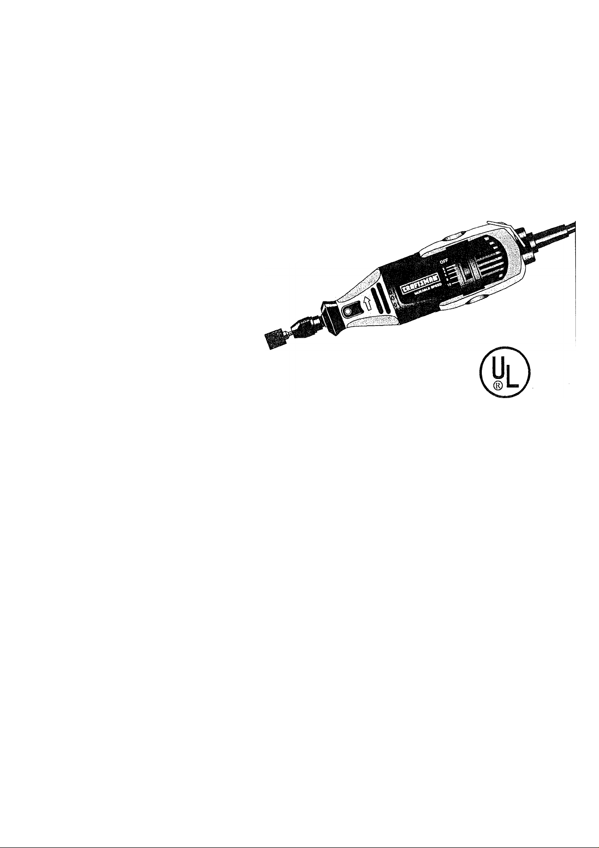
ROTARY POWER TOOLS
Model Nos.
572.610830
572.610960
&
572.610950
Caution:
Before using this product,
read this manual and follow
all its Safety Rules and
Operating Instructions.
Sears, Roebuck and Co., Hoffman Estates, IL 60179
« Safety
® Operation
* Maintenance
« Parts
® Español
2610913327
Page 2

Table of Contents Page
Warranty .................................................................................................... 2
Power Tool Safety Rules ........................................................................3-6
Symbols ....................................................................................................7
Functional Description and Specifications ............................................8-9
Assembly..............................................................................................10-II
Operating Instructions
Assembly & Operation of Attachments...............................................16-20
Maintenance .....................................................................................21-22
Accessories........................................................................................23-25
Operating Speeds for Accessories
Service Parts.....................................................................................28-31
Español .............................................................................................32-56
Sears Warranty
Full One Year Warranty on Craftsman Rotary Power Tool
.........'................................................................
...................................................
12-15
26-27
If this Craftsman Rotary Power Tool fails to give complete satisfaction within one
year from the date of purchase, Sears will replace it free of charge.
If this Rotary Power Tool is used for commercial or rental purposes, this warranty
applies for only one year from the date of purchase.
Warranty Service
Warranty service is available by returning this Craftsman Rotary Power Tool to your
nearest Sears Store in the United States.
This warranty applie's only while this Rotary Power Tool is used in the United
States.
This warranty gives you specific legal rights, and you may also have other rights
which vary from state to state.
Sears, Roebuck and Co., Dept. 81 TWA, Hoffman Estates, IL 60179
Page 3

POWER TOOL SAFETY RULES
A WARNING
Work Area
Keep your work area clean and well lit.
Cluttered benches and dark areas invite
accidents.
Do not operate power tools in explosive
atmospheres, such as in the presence of
flammable liquids, gases, or dust. Power
tools create sparks which may ignite the
dust or fumes.
Keep by-standers, children, and visitors
away while operating a power tool.
Distractions can cause you to lose control.
Electrical Safety
Double Insulated tools are equipped with
a polarized piug (one blade is wider than
the other.) This plug will fit in a polarized
outlet only one way. If the plug does not
fit fully in the outlet, reverse the plug. If it
stili does not fit, contact a qualified
electrician to instali a polarized outlet.
Do not change the plug in any way.
Double Insulation ^ eliminates the need
for the three wire grounded power cord and
grounded power supply system. Before
plugging in the tool, be certain the outlet
voltage supplied is within the voltage
marked on the nameplate. Do not use “AC
only” rated tools with a DC power supply.
Avoid body contact with grounded
surfaces such as pipes, radiators, ranges
and refrigerators. There is an increased
risk of electric shock if your body is
grounded. If operating the power tool in
damp locations is unavoidable, a Ground
Fault Circuit Interrupter must be used to
supply the power to your tool. Electrician’s
rubber gloves and footwear will further
enhance your personal safety.
Don't expose power tools to rain or wet
conditions. Water entering a power tool
will increase the risk of electric shock.
Do not abuse the cord. Never use the
cord to carry the tools or pull the plug
from an outlet. Keep cord away from
heat, oil, sharp edges or moving parts.
Replace damaged cords immediately.
Damaged cords increase the risk of electric
shock.
Read and understand all instructions. Failure to follow ail instructions
listed below, may result in electric shock, fire and/or serious personal injury.
SAVE THESE INSTRUCTIONS
When operating a power tool outside,
use an outdoor extension cord marked
"W-A” or “W.” These cords are rated for
outdoor use and reduce the risk of electric
shock. Refer to “Recommended sizes of
Extension Cords” in the Accessory section
of this manual.
Personal Safety
Stay alert, watch what you are doing and
use common sense when operating a
power tool. Do not use tool while tired or
under the influence of drugs, alcohol, or
medication. A moment of inattention while
operating power tools may result in serious
personal injury.
Dress properly. Do not wear loose
clothing or jewelry. Contain long hair.
Keep your hair, clothing, and gloves
away from moving parts. Loose clothes,
jewelry, or long hair can be caught in
moving parts. Keep handles dry, clean and
free from oil and grease.
Avoid accidental starting. Be sure switch
is “OFF” before piugging in. Carrying
tools with your finger on the switch or
plugging in tools that have the switch “ON”
invites accidents.
Remove adjusting keys or wrenches
before turning the tool “ON”. A wrench or
a key that is left attached to a rotating part
of the tool may result in personal injury.
Do not overreach. Keep proper footing
and balance at all times. Proper footing
and balance enables better control of the
tool in unexpected situations.
Use safety equipment. Always wear eye
protection. Dust mask, non-skid safety
shoes, hard hat, or hearing protection must
be used for appropriate conditions.
Tool Use and Care
Use clamps or other practical way to
secure and support the workpiece to a
stable platform. Holding the work by hand
or against your body is unstable and may
lead to loss of control.
Do not force tool. Use the correct tool for
your application. The correct tool will do
the job better and safer at the rate for which
it is designed.
Page 4

Do not use tool if switch does not turn it
“ON” or “OFF”. Any tool that cannot be
controlled with the switch Is dangerous and
must be repaired.
Disconnect the plug from the power
source before making any adjustments,
changing accessories, or storing the
tool. Such preventive safety measures
reduce the risk of starting the tool
accidentally.
of children and other untrained persons.
Tools are dangerous in the hands of
untrained users.
Maintain tools with care. Keep cutting
tools sharp and clean. Properly
maintained tools, with sharp cutting edges
are less likely to bind and are easier to
control. Any alteration or modification is a
misuse and may result in a dangerous
condition.
Check for misalignment or binding of
moving parts, breakage of parts, and any
other condition that may affect the tools
operation. If damaged, have the tool
serviced before using. Many accidents are
Store idle tools out of reach
SAFETY RULES FOR ROTARY TOOLS
caused by poorly maintained tools. Develop
a periodic maintenance schedule for your
tool.
Use only accessories that are
recommended by the manufacturer for
your model. Accessories that may be
suitable for one tool, may become
hazardous when used on another tool.
Service
Tool service must be performed only by
qualified repair personnel. Service or
maintenance performed by unqualified
personnel could result in a risk of injury. For
example: internal wires may be misplaced
or pinched, safety guard return springs may
be improperly mounted.
When servicing a tool, use only Identical
replacement parts. Follow instructions in
the Maintenance section of this manual.
Use of unauthorized parts or failure to
follow Maintenance Instructions may create
a risk of electric shock or injury. Certain
cleaning agents such as gasoline, carbon
tetrachloride, ammonia, etc. may damage
plastic parts.
Accessories must be rated for at ieast
the speed recommended on the tool
warning labei. Wheels and other
accessories running over rated speed can
fly apart and cause injury.
Hold tool by insulated gripping surfaces
when performing an operation where the
cutting tool may contact hidden wiring or
its own cord. Contact with a “live" wire will
make exposed metal parts of the tool "live”
and shock the operator. If cutting into
existing wails or other blind areas where
electrical wiring may exist is unavoidable,
disconnect all fuses or circuit breakers
feeding this worksite.
The following warning is intended for flex
shaft tools and accessories: Do not
operate the flexible shaft with a sharp
bend. Over bending the shaft can generate
excessive heat on the jacket or hand piece.
The recommended minimum is 6" radius.
Always disconnect the power cord from
the power source before making any
adjustments or attaching any
accessories. You may unexpectedly cause
the tool to start leading to serious personal
injury.
Be aware of the switch location, when
placing the tool down or when picking
the tool up. You may accidentally activate
the switch. ,
The following warning is intended for flex
shaft tools and accessories: Always hold
the hand piece firmly in your hands
during the start-up. The reaction torque of
the motor, as it accelerates to full speed,
can cause the shaft to twist.
Always hold the tool with two hands
during start-up. The reaction torque of the
motor can cause the tool to twist.
Always wear safety goggles and dust
mask. Use only in well ventilated area.
Using personal safety devices and working
in safe environment reduces risk of injury.
After changing the bits or making any
adjustments, make sure the collet nut
and any other adjustment devices are
securely tightened. Loose adjustment
device can unexpectedly shift, causing loss
of control, loose rotating components will
be violently thrown.
Do not reach in the area of the spinning
bit. The proximity of the spinning bit to your
hand may not always be obvious.
Page 5

Allow brushes to run at operating speed
for at least one minute before using
wheel. During this time no one is to stand
in front or in line with the brush. Loose
bristles or wires will be discharged during
the run-in time.
Wire and bristle brushes must never be
operated at speeds greater than
15,000/min. Direct the discharge of the
spinning wire brush away from you.
Small particles and tiny wire fragments may
be discharged at high velocity during the
“cleaning” action with these brushes and
may become imbedded in your skin.
Bristles or wires wiil be discharged from the
brush at high speeds.
Wear protective gloves and face shield
with wire or bristle brushes. Apply wire
or bristle brushes lightly to the work as
only the tips of the wire/bristles do the
work. “Heavy” pressure on bristles will
cause the wire or bristle to become
overstressed, resulting in a wiping action
and will cause the bristles/wire to be
discharged.
Carefully handle both the tool and
individual grinding wheels to avoid
chipping or cracking. Install a new wheel
if tool is dropped while grinding. Do not
use a wheel that may be damaged.
Fragments from a wheel that bursts during
operation will fly away at great velocity
possibly striking you or bystanders.
Never use dull or damaged bits. Sharp
bits must be handled with care.
Damaged bits can snap during use. Dull bits
require more force to push the tool,
possibly causing the bit to break.
Use clamps to support workpiece
whenever practical. Never hold a small
workpiece in one hand and the tool in the
other hand while in use. Allow for
sufficient space, at least 6", between
your hand and the spinning bit. Round
material such as dowel rods, pipes or
tubing have a tendency to roll while being
cut, and may cause the bit to “bite” or jump
toward you. Clamping a small workpiece
allows you to use both hands to control the
tool.
Inspect your workpiece before cutting.
When cutting irregularly shaped
workpieces, plan your work so it will not
slip and pinch the bit and be torn from
your hand. For example, if carving wood,
make sure there are no nails or foreign
objects in the workpiece. Nails or foreign
objects can cause the bit to jump.
Never start the tool when the bit is
engaged in the material. The bit cutting
edge may grab the material causing loss of
control of the cutter. ,
Avoid bouncing and snagging the wheel,
especially when working corners, sharp
edges etc. This can cause loss of control
and kick-back.
The direction of feed with the bit into the
material when carving, routing or cutting
is very important. Always feed the bit
into the material in the same direction as
the cutting edge is exiting from the
material (which is the same direction as
the chips are thrown). Feeding the tool in
the wrong direction, causes the cutting
edge of the bit to climb out of the work and
pull the tool in the direction of this feed.
If the workpiece or bit becomes jammed
or bogged down, turn the tool “OFF” by
the switch. Wait for all moving parts to
stop and unplug the tool, then work to
free the jammed material. If the switch to
the tool is left “ON” the tool could restart
unexpectedly causing serious personal
injury.
Do not leave a running tool unattended,
turn power off. Only when tool comes to a
complete stop it is safe to put it down.
Do not grind or sand near flammable
materials. Sparks from the wheel could
ignite these materials.
Do not touch the bit or collet after use.
After use the bit and collet are too hot to be
touched by bare hands.
Regularly clean the tool's air vents by
compressed air. Excessive accumulation
of powdered metal inside the motor housing
may cause electrical failures.
Do not allow familiarity gained from
frequent use of your rotary tool to
become commonplace. Always remember
that a careless fraction of a second is
sufficient to inflict severe injury.
Do not alter or misuse tool. Any alteration
or modification is a misuse and may result
in serious personal injury.
This product is not intended for use as a
dental drill, in human or veterinary
medical applications. Serious personal
injury may result.
Page 6

When using the steel saws, cutoff
wheels, high speed cutters or tungsten
carbide cutters, always have the work
securely clamped. Never attempt to hold
the work with one hand while using any
of these accessories. The reason is that
these wheels will grab if they become
slightly canted in the groove, and can kick
back causing loss of control resulting in
serious injury. Your second hand should be
used to steady and guide the hand holding
the tool. When a cutoff wheel grabs, the
wheel itself usually breaks. When the steel
saw, high speed cutters or tungsten carbide
cutter grab, it may jump from the groove
and you could lose control of the tool.
A WARNING
grinding, drilling, and other construction
activities contains chemicals known to
cause cancer, birth defects or other
reproductive harm. Some examples of
these chemicals are;
• Lead from lead-based paints,
• Crystalline silica from bricks and cement
and other masonry products, and
• Arsenic and chromium from chemically-
treated lumber.
Your risk from these exposures varies,
depending on how often you do this type of
work. To reduce your exposure to these
chemicais: work in a well ventilated area,
and work with approved safety equipment,
such as those dust masks that are specially
designed to filter out microscopic particles.
Some dust created by
power sanding, sawing,
Page 7

SYMBOLS
IMPORTANT; Some of the following symbols may be used on your tool. Please study them
and learn their meaning. Proper interpretation of these symbols will allow you to operate the
tool better and safer. '
0
Name
Hertz
Watt
Kilograms Weight
Minutes Time
Seconds
Diameter
No load speed
Off position
Selector settings
Infinitely variable selector with off Speed is increasing from 0 setting
Arrow
Alternating current
=
Direct current
Alternating or direct current Type or a characteristic of current
Class II construction Designates Double insulated
Earthing terminal Grounding terminal
©
Warning symbol
A
Ni-Cad RBRC™ seal Designates Ni-Cad battery recycling
Designatlon/Explanation
Voltage (potential)
Frequency (cycles per second)
Power
Time
Size of drill bits, grinding wheels, etc.
Rotational speed, at no load
orbits etc. per minute
Zero speed, zero torque... ,
Speed, torque or position settings.
Higher number means greater speed
Action in the direction of an'ow
Type or a characteristic of current
Type or a characteristic of current
Construction tools.
Alerts user to warning messages
program
Symbol
V Volts
A Amperes Current
Hz
W
kg
i min
s
no
.../min Revolutions or reciprocation per minuteRevolutions, strokes, surface speed,
0
1,2,3....
I, II, III,
-►
This symbol designates
that this tool is listed by
Underwriters Laboratories.
This symbol designates
that this tool is listed by
the Canadian Standards
Association.
This symboi designates
that this tool is li,sted to
Canadian Standards by
Underwriters Laboratories.
Page 8
FUNCTIONAL DESCRIPTION AND SPECIFICATIONS
A WARNING
Disconnect the plug from the power source before making any
assembly, adjustments or changing accessories. Such preventive
safety measures reduce the risk of starting the tool accidentally.
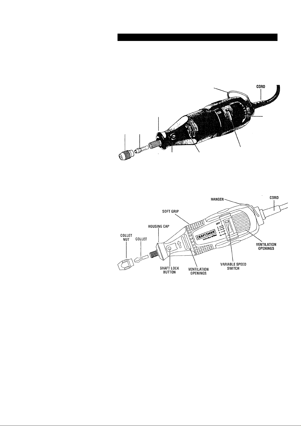
Rotary Tool 610830 & 610960
HANGER-
HOUSING CAP
COLLET
NUT COLLET
SWITCH
SHAFT LOCK
BUnON
VENTILATION
OPENINGS
(610830 SINGLE SPEED)
(610060 TWO SPEED)
Rotary Tool 610950
VENTILATION
OPENINGS
NOTE; For tool specifications refer to the nameplate on your tool.
Page 9
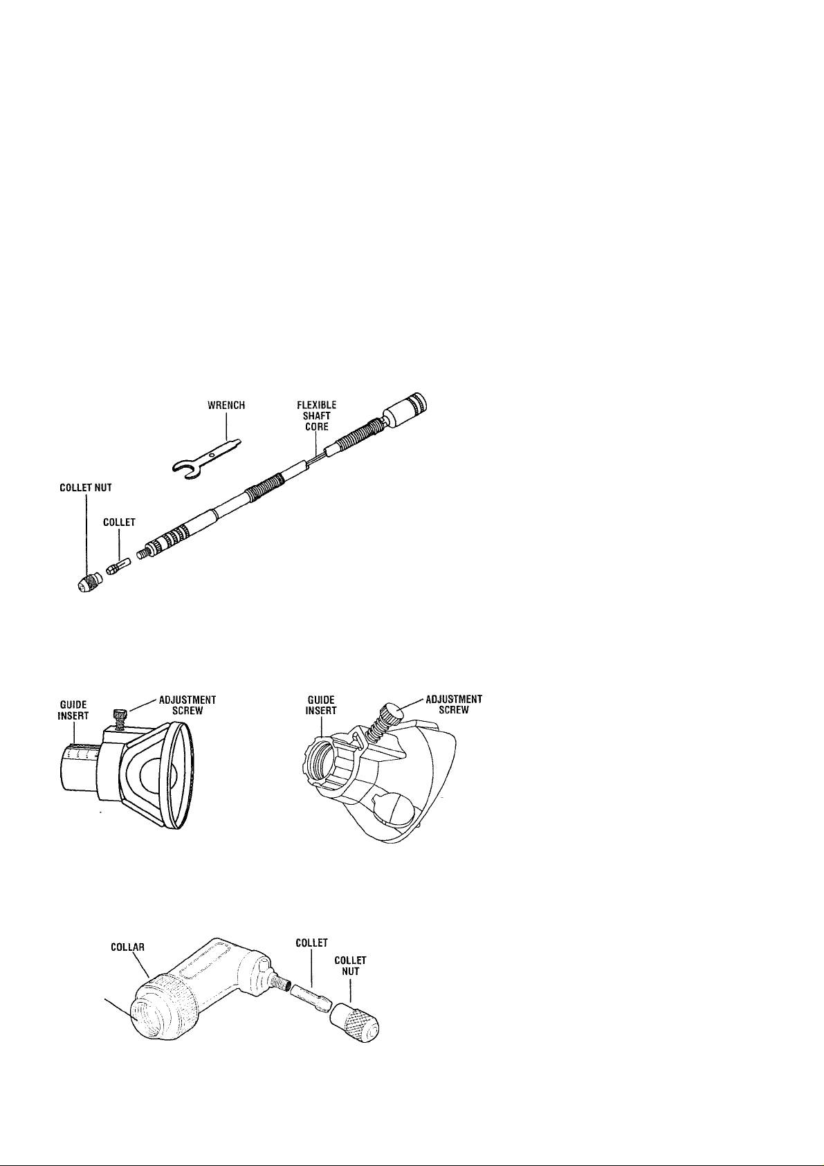
Flex-Shaft 53033
DRIVER
CAP
Cutting Guide 53141
DEPTH
Right Angie Attachment 53002
ADAPTER
Grout Removal Kit 53052
DEPTH
Page 10
ASSEMBLY
A WARNING
Always unplug rotary tool
before changing acces
sories, changing collets or servicing your
rotary tool.
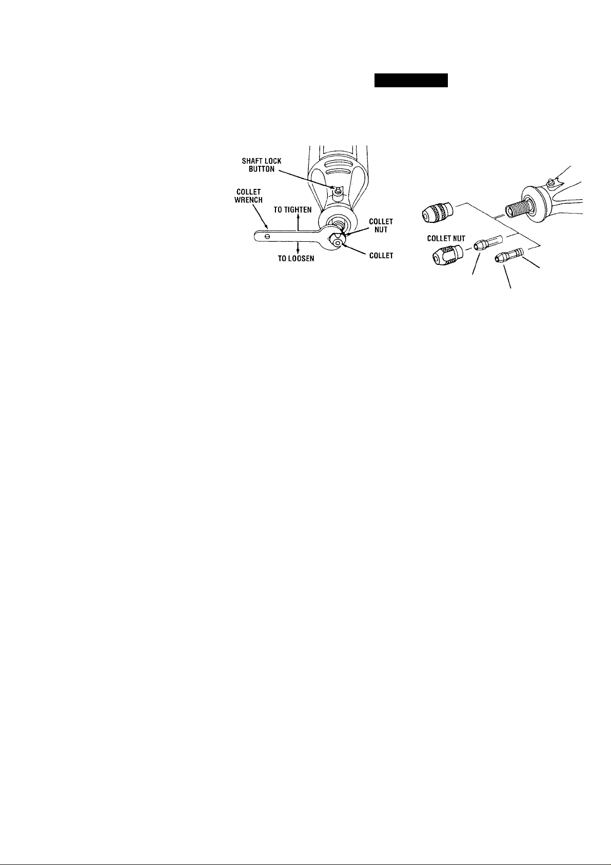
COLLET — To loosen, first press shaft lock
button and rotate the shaft by hand until the
lock engages the shaft preventing further
rotation.
A CAUTION
Do not engage lock while
the Rotary Tool is running.
With the shaft lock engaged use the collet
wrench to loosen the collet nut if necessary.
Change accessories by inserting the new
one into the collet as far as possible to
minimize runout and unbalance. With the
shaft lock engaged, finger tighten the collet
nut until the accessory shank is gripped by
the collet Avoid excessive tightening of the
collet nut. The collet system is a superior
method of securing accessories.
COLLETS — Two different size coilets (see
illustration), to accommodate different shank
sizes, are available for your Rotary Tool. To
install a different collet, remove the collet nut
and remove the old collet. Insert the
unslotted end of the collet in the hole in the
end of the tool shaft. Replace collet nut on
the shaft. Always use the collet which
matches the shank size of the accessory
you plan to use. Never force a larger
diameter shank into a collet.
BALANCING ACCESSORIES - For
precision work, it is important that all
accessories be in good balance (much the
same as the tires on your automobile). To
true up or balance an accessory, slightly
loosen collet nut and give the accessory Or
COLLET IDENTIFICATION CHART — Collet sizes can
be identified by the rings on the back end of collet.
1/32" Collet has one (1)ring.
1/16" Collet has two (2) rings.
3/32" Collet has three (3) rings.
1/8 " Collet has no rings.
KEYLESS CHUCK
IDENTIFICATION
1/8“ COLLET
3/32" COLLET
RINGS
collet a 1/4 turn. Retighten collet nut and run
the Rotary Tool. You should be able to tell
by the sound and feel if your accessory is
running in balance. Continue adjusting in this
fashion until best balance is achieved. To
maintain balance on abrasive wheel points,
before each use, with the wheel point
secured in the collet, turn on the Rotary Tool
and run the Dressing Stone lightly against
the revolving wheel point. This removes high
spots and trues up the wheel point for good
balance.
The hanger is provided for the use of
hanging your tool while using the flex-shaft
or for storage. If you do not use the hanger,
remove it from the tool and snap it back into
place underneath the cord so it will be out of
the way while the tool is in use.
Remember, your new Craftsman Rotary Tool
is the finest power tool of its kind. But its
performance is only as good as the
accessories with which it is used.
We recommend only Craftsman
accessories be used. Use of any other
accessories may create a hazard. We hope
you’ll enjoy many years of trouble free
pleasure from your Sears Craftsman Rotary
Power Tool.
10
Page 11

KEYLESS CHUCK - The keyless chuck
holds various accessories with shank sizes
1/32" to 1/8" and is intended for light duty
accessories such as drill bits, sanding
drums,
bristle brushes and cut-off wheels. The
keyless chuck allows you to change
accessories frequently, quickly and easily.
There are some applications which can
generate high forces on the bit or If you are
unable to generate finger tightening pressure
sufficient to secure the bit you must use the
supplied wrench to assist in securing the bit.
Attaching the Keyless Chuck and
Accessory Bit
keyless chuck with the tool. Insert and
securely tighten the shank of the
accessory well within the jaws of the
chuck. If an accessory is not properly
gripped within the jaws of a chuck it may
loosen and fly out during use possibly
striking you or bystanders.
To replace or attach the keyless chuck
accessory to your MultiPro rotary tool,
unplug the tool and engage the shaft lock
button then remove the collet and collet nut.
Thread the keyless chuck on the end of the
shaft. Engage the shaft lock button again.
polishing accessories, wire and
ik WARNING
Read and understand the
manual for use of the
insert the accessory shank into the chuck
and finger tighten until the shank is secure.
For small size drill bits, close the chuck to
the point where the bit will just fit in; then
tighten securely. This helps center the bit in
the keyless chuck correctly. In some high
force applications such as removing metal,
tile cutting or routing, the bit (tungsten
carbide cutters, high speed cutters, router
bits or tile cutters) and chuck will become
hot if overloaded for extended periods of
time. Overloading the chuck may cause the
bit to loosen and slip. It is recommended
that in these types of applications that the
bit be secured in the chuck with the supplied
wrench and work in intervals to allow cooling
of the bit and chuck. If the bit slips the tool
will begin to vibrate excessively, this is an
indication that you should shut the tool off,
re-position and tighten the bit then allow the
tool to run no-load for a few minutes to cool.
The chuck should be cleaned occasionally to
keep it functioning properly. Simply remove
the chuck from the tool and gently tap the
tip of the chuck on a fat surface to remove
any loose debris, in some applications the
keyless chuck may tighten up during use. If
this occurs, gently loosen using the wrench
included in your rotary tool kit.
11
Page 12
OPERATING INSTRUCTIONS
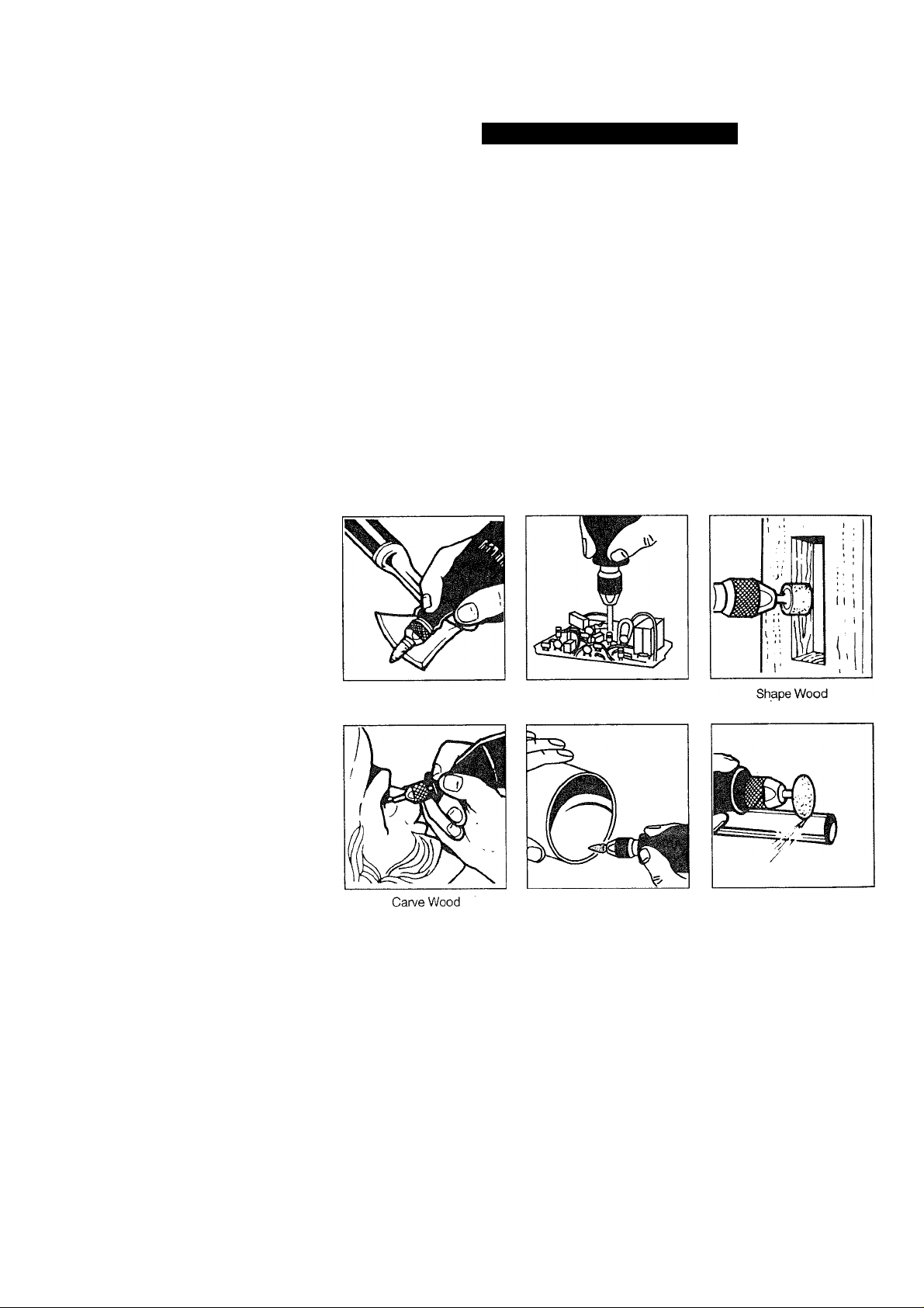
The Rotary Tool is a handful of high-speed
power. It serves as a carver, grinder,
polisher, Sander, cutter, power brush, drill
and more.
The Rotary Tool has a small, powerful
electric motor, is comfortable in the hand,
and is made to accept a large variety of
accessories including abrasive wheels, drill
bits, wire brushes, polishers, engraving
cutters, router bits, and cutting wheels.
Accessories come in a variety of shapes and
permit you to do a number of different jobs.
As you become familiar with the range of
accessories and their uses, you will learn just
how versatile the Rotary Tool is. You'll see
dozens of uses you hadn’t thought of before.
The real secret of the Rotary Tool is its
speed. To understand the advantages of its
high speed, you have to know that the
standard portable electric drill runs at
speeds up to 2,800 revolutions per minute.
The Rotary Tool operates at speeds up to .
35,000 revolutions per minute. The typical
electric drill is a low-speed, high torque tool;
the Rotary Tool is just the opposite - a high
speed, low torque tool. The chief difference
to the user is that in the high speed tools,
the speed combined with the accessory
mounted in the collet does the work. You
don’t apply pressure to the tool, but simply
hold and guide it. In the low speed tools, you
not only guide the tool, but also apply
pressure to it, as you do, for example, when
drilling a hole.
It is this high speed, along with its compact
size and wide variety of special accessories,
that makes the Rotary Tool different from
other power tools. The speed enables it to
do jobs low speed tools cannot do, such as
cutting hardened steel, engraving glass, etc.
Getting the most out of your Rotary Tooi is a
matter of learning how to let this speed work
for you.
Sharpen Tools
Precise Drilling
Deburr Metal
12
Cut Metal
Page 13
USING THE ROTARY POWER TOOL
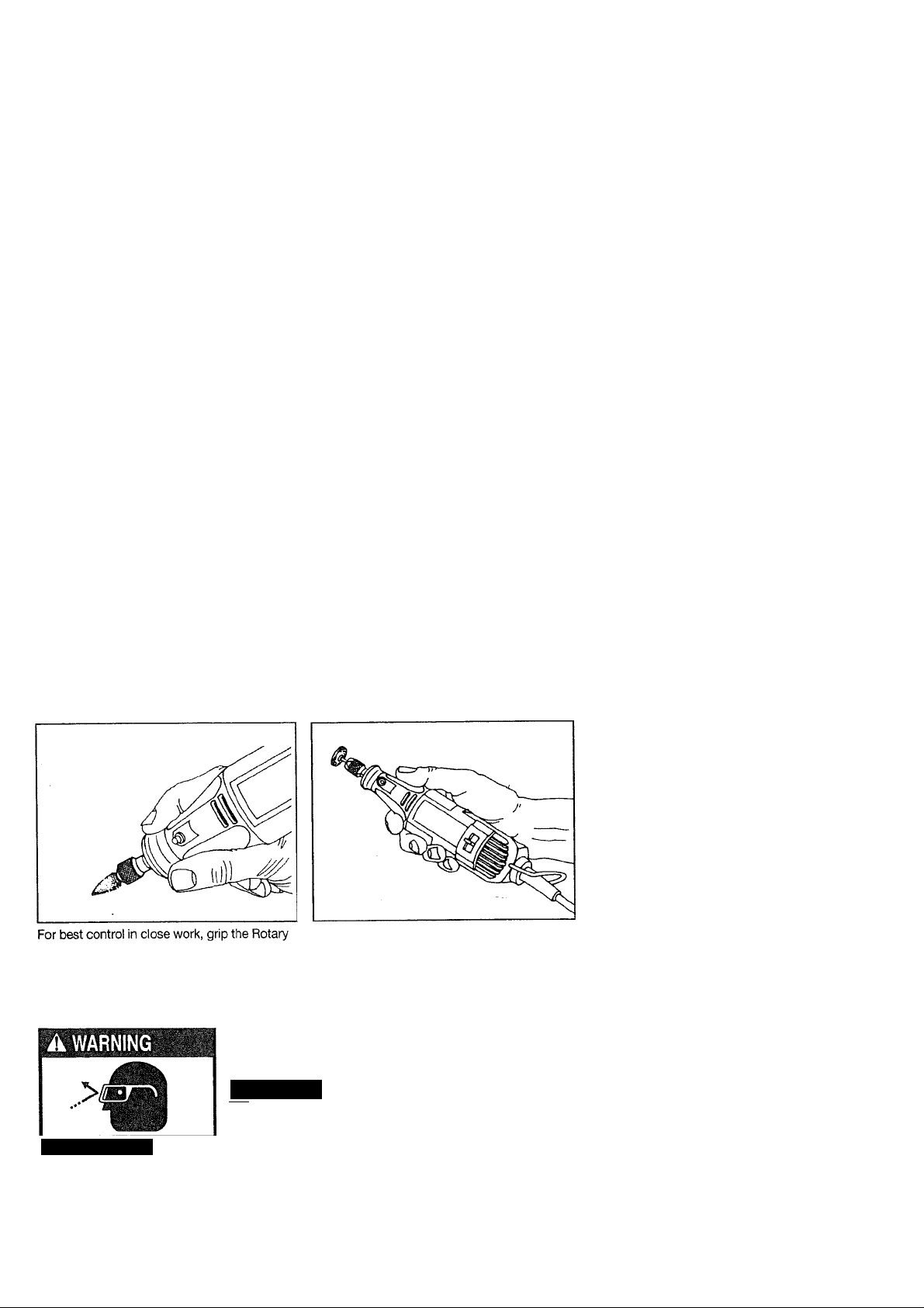
The first step in learning to use the Rotary
Tool is to get the “feel” of it. Hold it in your
hand and feel its weight and balance. Feel
the taper of the housing. This taper permits
the Rotary Tool to be grasped much like a
pen or pencil. The Variable Speed tool has a
unique comfort grip on the nose and back
seating, which allows the user added
comfort and control during use. You can feel
the difference!
When you turn on the tool for the first time,
hold it away from your face. Accessories can
be damaged during handling, and can fly
apart as they come up to speed. This is not
common, but it may happen.
Practice on scrap materials first to see how
the Rotary Tooi cuts. Keep in mind that the
work is done by the speed of the tool and by
the accessory in the collet. You should not
‘ lean on or push the tool into the work.
Instead, lower the spinning accessory lightly
to the work and allow it to touch the point at
which you want cutting (or sanding or
etching, etc.) to begin. Concentrate on
guiding the tool over the work using veiy
little pressure from your hand. Allow the
accessory to do the work. •
Usually, it is best to make a series of passes
with the tooi rather than attempt to do all the
work in one pass. To make a cut, for
example, pass the tool back and forth over
the work, much as you would a small paint
brush. Cut a little material on each pass until
you reach the desired depth. For most work,
the gentle touch is best. With it, you have
the best control, are less likely to make
errors, and will get the most efficient work
out of the accessory.
Tool like a pencil between your thumb and
forefinger.
A CAUTION
—..
.................
This blocks the air flow and causes the motor to overheat.
Wear Eye Protection
The “handgrip” method of holding the tool is
used for operations such as grinding a flat
surface or using cutoff wheels.
Whenever you hold the tool, be careful
not to cover the air vents with your hand.
13
Page 14
OPERATING SPEEDS
Set the speed indicator to fit the job; to achieve
the best job results when working with different
materials, the speed of the Rotary Tool should
be regulated.
A CAUTION
Models 610960 & 610950
Rotary Tools have an
integral speed control and an external
speed control should never be used with
these tools.
To select the right speed for each job, use a
practice piece of material. Vary speed to find
the best speed for the accessory you are using
and the job to be done.
NOTE: Speed is affected by voltage
changes. A reduced incoming voltage will
Slow speeds (15,000 RPM or less) usually are
best for polishing operations employing the felt
polishing accessories. They may also be best
for working on delicate projects as “eggery”
work, delicate wood carding and fragile model
parts. All brushing applications require lower
speeds to avoid wire discharge from the
holder.
Higher speeds are better for carving, cutting,
routing, shaping, cutting dadoes or rabbets in
wood.
Hardwoods, metals and glass require high
speed operation, and drilling should also be
done at high speeds.
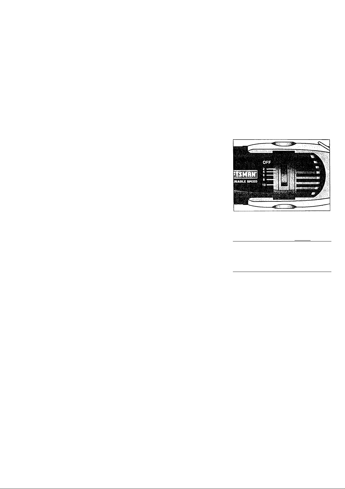
The speed of the Rotary Tool is controlled
by setting this indicator on the housing.
slow the RPM of the tool, especially at the
lowest setting. If your tool appears to be
running slowly increase the speed setting
accordingly.
There are three basic types of Rotary Tools:
single speed, two-speed and variable speed
models.
• Single speed has one ON-OFF switch.
When the switch is on, the tool runs at
35,000 RPM.
• On the two-speed-model, there is a LO and
HI switch. When the switch indicator is on
the low setting, the tool runs at about 15,000
RPM. When the switch indicator is on the
high setting, the tool runs at about 35,000
RPM.
• On the variable speed model, there are
switch setting indicators marked with a
line. Slide to the number on the housing to
select the operating speed needed from
5,000-35,000 RPM.
You can refer to the charts on pages 26 & 27
to determine the proper speea, based on the
material being worked and the type o* cvstter o:
other accessory being used. These charts
enable you to select both the correct acces
sory and the optimum speed at
a glance,
if you have a single-speed or two-speed
model, you will be able to use many
accessories to do a wide assortment of jobs.
For the majority of applications, all models of
the Rotary Tool should be used at top speed.
NEEDS FOR SLOWER SPEEDS
Certain materials, however, (some plastics, for
example) require a relatively slow speed
because at high speed the friction of the
accessory generates heat and causes the '
plastic to melt.
The Settings for Approximate Revolutions
Per Minute Rotary Tool Variable Speed
Model 610950.
Switch Setting Speed Range
2
*4
g
s
1
'Model 6109b0 W:r-: Br
5,000- 8,000 RPM
9,000-11,000 RPM
12.000-17,000 RPM
18,000-24,000 RPM
25,000-35,000 RPM
sitina.
The point to re.member rs this: You can do the
great majority of work with the single speed at
its regular speed of 35.000 RPM. But for
certain materials and types of work, you need
slower speeds — which is the reason the
variable speed models were developed.
To aid you in determining the optimum
operational speed for different materials and
different accessories, we have constructed a
table that appears on pages 26 & 27. By
referring to this table, you can determine the
recommended speeds for each type of
Page 15
accessory. Look this table over and become
familiar with it.
Ultimately, the best way to determine the
correct speed for work on any material is to
practice for a few minutes on a piece of
scrap, even after referring to the chart. You
can quickly learn that a slower or faster
speed is more effective just by observing
what happens as you make a pass or two at
different speeds. When working with plastic,
for example, start at a slow rate of speed
and increase the speed until you observe
that the plastic is melting at the point of
contact. Then reduce the speed slightly to
get the optimum working speed.
Some rules of thumb in regard to speed:
1. Plastic and materials that melt at low
i temperatures should be cut at low
, speeds.
2. Polishing, buffing and cleaning with a wire
brush must be done at speeds not greater
than 15,000 RPM to prevent damage to
the brush.
3. Wood should be cut at high speed.
4. Iron or steel should be cut at high speed if
using tungsten carbide accessory, but at
slower speeds if using high speed steel
cutters. If a high speed steel cutter starts
to chatter — this normally means it is
running too slow.
5. Aluminum, copper alloys, lead alloys, zinc
alloys and tin may be cut at various
speeds, depending on the type of cutting
being done. Use paraffin or other suitable
lubricant on the cutter to prevent the cut
material from adhering to the cutter teeth.
Increasing the pressure on the tool is not the
answer when it is not cutting as you think it
should. Perhaps you should be using a
different cutter, and perhaps an adjustment
in speed would solve the problem. Leaning
on the tool does not help. The correct speed
will make using the rotary tool effortless.
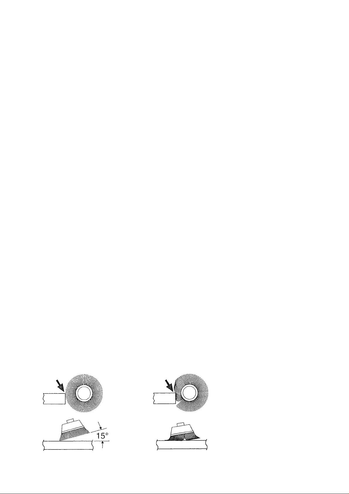
BRUSHING PRESSURE
1. Remember, the tips of a wire brush do the
work. Operate the brush with the lighte.st
pressure so only the tips of the wire come in
contact with the work.
2. If heavier pressures are used, the wires
will be overstressed, resulting in a wiping
action; and if this is continued, the life of the
CORRECT:
Wire tips
doing the
work.
15
brush will be shortened due to wire fatigue.
3. Apply the brush to the work in such a way
that as much of the brush face as possible is
in full contact with the work. Applying the
side or edge of the brush to the work will
result in wire breakage and shortened brush
life.
INCORRECT;
Excessive
pressure can
cause wire
breakage.
Page 16
ASSEMBLY & OPERATION OF ATTACHMENTS
AWARNING
will cause kickback.
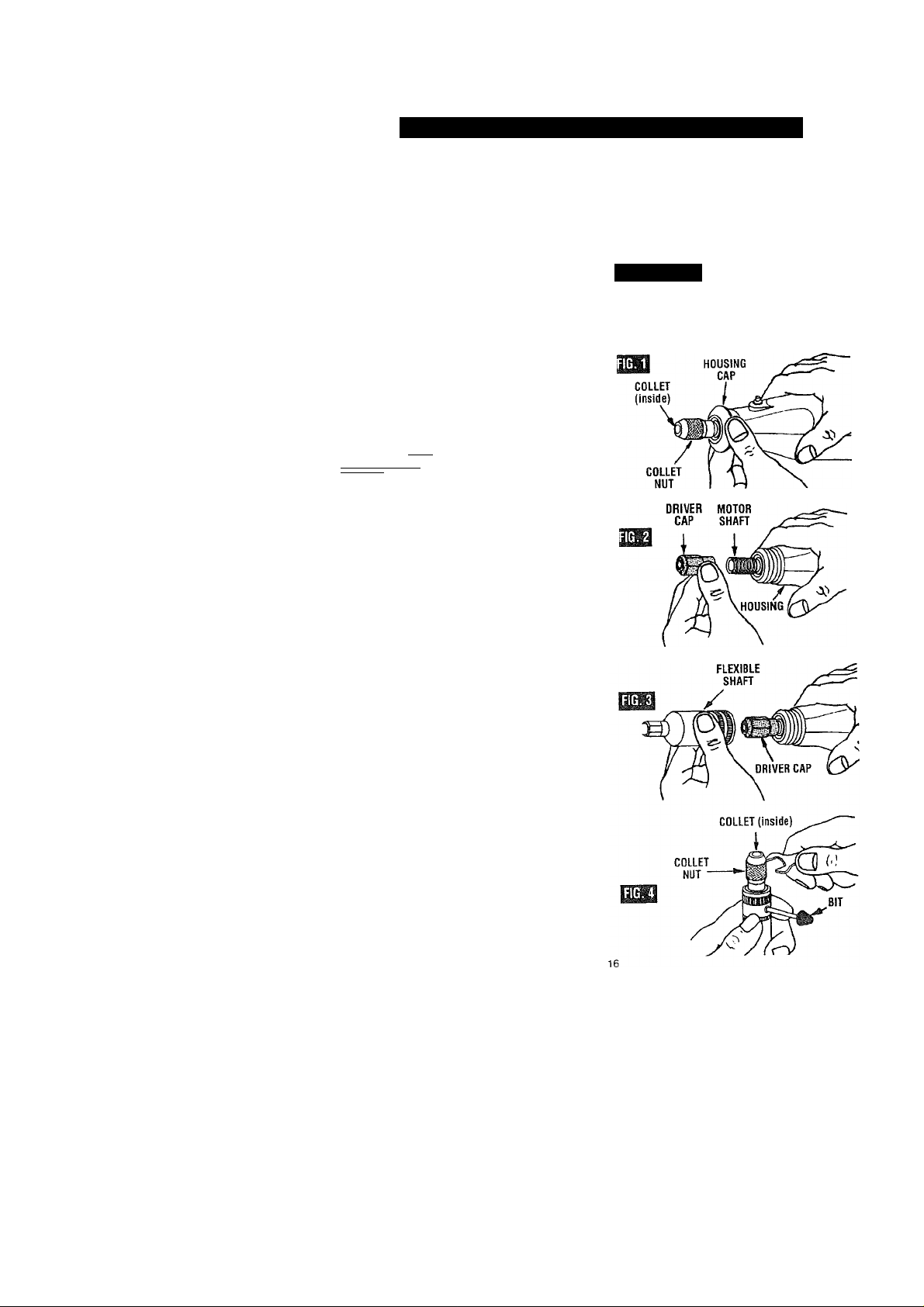
1, To attach the 53033 flex-shaft {sold
separately) to the Rotary Tool remove the
housing cap from the tool as shown in
Figure 1. Then press the shaft lock and
unscrew the collet nut and remove the
collet. Install the driver cap on the motor
shaft as shown in Figure 2 and tighten.
A CAUTION
driver cap. Tighten the driver cap finger
tight and then tighten an additional 1/3 turn
with the wrench. (Wrench included with your
Rotary Tool kit).
2. Screw the flexible shaft onto the Rotary
Tool housing being sure that the square
end of the center core engages the square
hole socket in the driver cap Figure 3.
■WMWItPjWM Do not pull out center
EjaflUliMkW core to engage into driver
cap. This could cause disengagement of
center core from handpiece. If tool stops
when shaft is bent, center core may be
lodged in driver cap. Loosen shaft and
remove core from driver cap. Then screw
flexible shaft onto rotary tool housing again.
Flex-Shaft Collet Assembly
The collet assembly consists of a collet nut
and collet. To change bits use the wrench
and a bit. Insert the shank portion of any bit
(1/8" shank recommended) through the
opening in the flex-shaft hand piece to lock
the shaft. With the shaft secured, use the
wrench to loosen or tighten the collet nut as
shown in Figure 4. With the collet nut loose,
insert an accessory or bit as deeply as
possible to avoid wobble during use.
Retighten the collet nut.
Collet Removal and Replacement
Four different size collets to accommodate
different shank sizes, are available for your
flex-shaft. To install a different collet, remove
the collet nut and remove the old collet.
Insert the unslotted end of the collet in the
hole in the end of the flex-shaft. Replace
collet nut on the shaft. Always use the
collet which matches the shank size of
the accessory you plan to use.
Never force a larger diameter shank into a
collet. -
Available Collets .
No. 53065 Collet Nut Kit -Includes one
1/8", 1/16", 1/32" & 3/32" collets and collet
nut.
Not for use with router
bits. Use with router bits
To prevent damage to
tool, do not overtighten
Flexible Shaft Lubrication
The flexible shaft should be lubricated after
every 25-30 hours of use. To lubricate,
unscrew the flexible shaft assembly from the
motor housing. Pull the center core out of
the flexible shaft assembly. Wipe a very thin
film of a good quality, high temperature
grease on to the center core.
A CAUTION
shaft. Too much grease will cause the unit
to overheat. Automotive wheel bearing
grease should be used.
Reattach the flex-shaft to the rotary tool.
To prevent damage to
tool do not over grease
Page 17
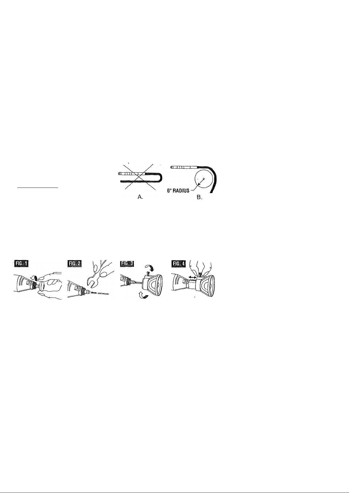
A WARNING
bend (A). This can generate excessive heat
and will reduce tool and flex-shaft life. The
recommended minimum is 6" radius (B).
Contents of 53033 Flex-shaft Attachment
Qtv. Description
1 Flex-Shaft Assembly (42" long)
1 Driver Cap
Do not operate the
flexible shaft with a sharp
Cutting Guide 53141
The cutting guide (sold separately) comes
completely assembled and ready to use. For
use in a variety of materials up to 3/4" thick.
Match the bit type to the material to be cut.
Always hold the tool firmly, using slow
53134
Drywall Cutting Bit
For use in drywall.
• When inserting the 53134 bit into your
Craftsman Rotary tool, make sure that the
bit has been inserted as far as possible.
• When making freehand cuts in drywall, ex., repairing a hole in drywall. When using
a template (outlet box) behind the drywall,
use the Drywall Cutting Bit 53134, cutting
in a counter-clockwise direction.
53135
Multipurpose Cutting Bit
For use in wood, plastics, drywaii,
fiberglass, vinyl or aluminum siding,
acoustical tile and laminates.
• When inserting the 53135 bit into your
Craftsman Rotary tool, make sure that the
bit has been inserted as far as possible.
• When making freehand cuts in use the
Multipurpose Cutting Bit 53135, cutting in a
clockwise direction.
c
T3
steady pressure to make cuts.
To attach, follow the four steps shown below.
Important: Always cut in a clockwise
direction, except when following a
template (outlet box), then cut in a
counterclockwise direction.
' When using 53135, Multipurpose Cutting
Bit, start the bit into the material at a 45
degree angle and then slowly bring it to a
90 degree angle to begin the cut.
53136
Tile Cutting Bit (Not Included)
For use on wall tile, cement board and
plaster
• When inserting the 53136 bit into your
Craftsman Rotary tool, it is very important
that 1/16”-1/8” of smooth shank remains
visible above the collet.
• When using 53136, Tile Cutting Bit, start
the bit into the material at a 45 degree
angle and then slowly bring it to a 90
degree angle to begin the cut.
• NOT FOR USE ON FLOOR TILE
17
Page 18
Grout Removal Kit 53052
The grout removal attachment comes completely
assembled and ready to use. Use the 1/16" bit that
comes with the grout removal kit for tiles spaced
more than 1/16" apart. If your tiles are spaced more
than 1/8" apart, it is recommended that you use the
53166 (1/8") bit (sold separately).
Note;
If the bit is too wide for the spacing between
your tiles, you may damage your tile or the grout
removal bit.
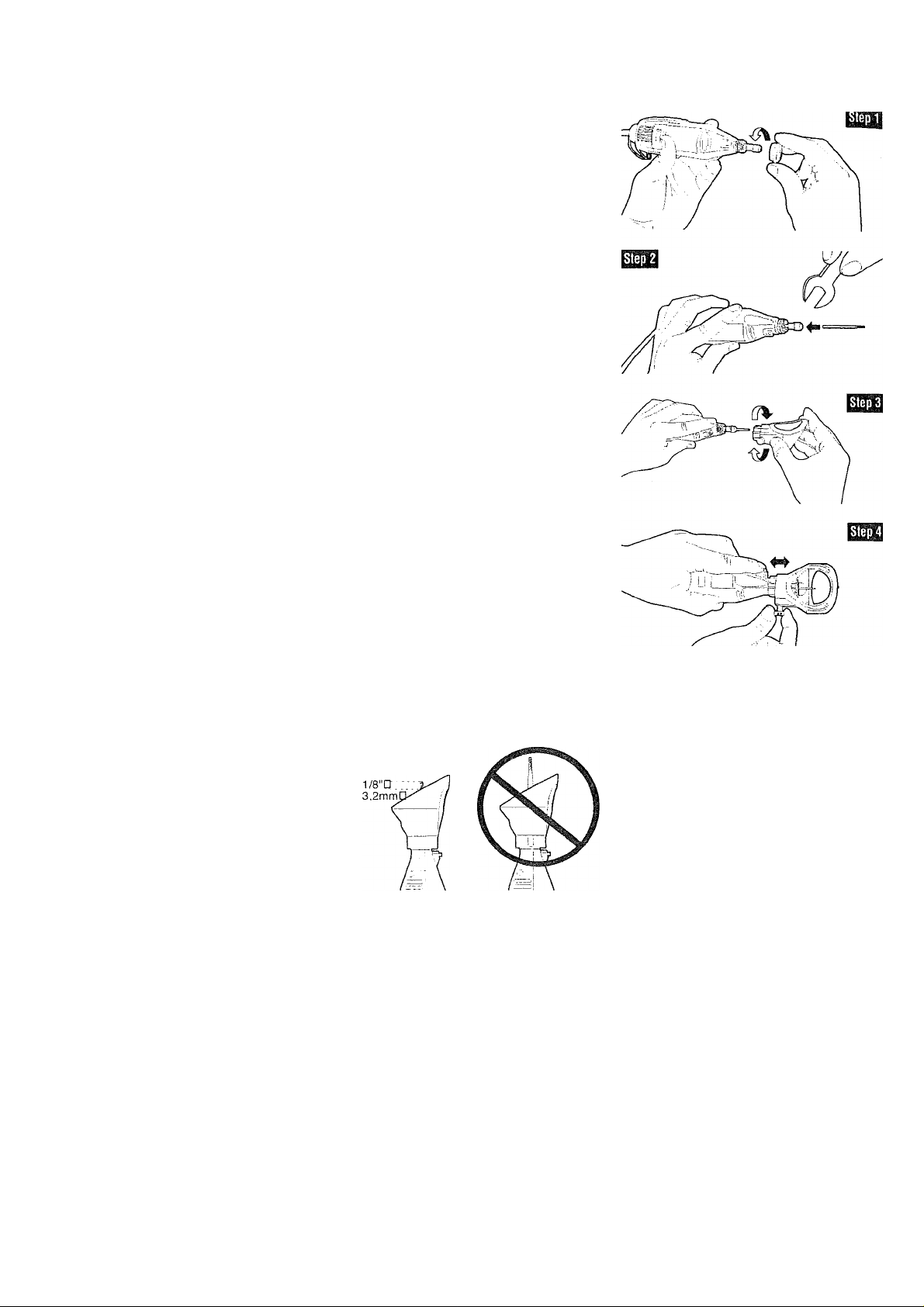
Step 1:
Remove the housing cap from the tool.
Step
2: Insert the grout removal bit into your rotary
tool.
A CAUTION
power tool, be sure that the bit is secure witbin tbe
“jaws" of the collet.
collet nut to prevent the bit from loosening within the
collet. Do not use your Craftsman Chuck, #53050,
with the grout removal bits.
Step 3:
Screw the grout removal attachment onto the
rotary tool.
Step 4:
Adjust the attachment and bit to the desired
cutting depth.
Grout Removal Attachment Cutting Depth
Adjustment
The Multi Slide Depth Adjustment has increment
markings of 1/8" (3,2 mm). These markings are for
reference only in identifying the depth of your desired
cut. The multiple channels of the depth adjustment let
you choose the orientation of the attachment to the
tool. Be sure to securely tighten the screw within one
of the multiple channel positions.
To set cutting depth:
Cleaning Grout:
Do not remove grout more than 1,''8“ below the face
surface of the tile. Adjust the Multi Slide Depth
Adjustment and bit so that no more than 1/8" of the
bit extends beyond the base of the attachment.
After removing 1,'8" of grout, regrout to tile level. Seal
the new grout. '
When inserting the #53166 grout
removai bit Into your rotary
Use the wrench to tighten the
Removing Grout to Replace A Broken Tile:
Remove all of the grout surrounding the broken tile.
Adjust the Multi Slide Depth Adjustment so that no
more than
the attachment. Remove grout at a depth no more
than 1,'8" at a time. You may need to adjust the Multi
Slide Depth Adjustment by 1/8" increments (reference
the 1/8" incremental white markings on the Multi Slide
Depth Adjustment) and make several passes until all
the grout is removed.
When removing grout deeper into the grout line, you
may strike hidden objects like screw heads, mortar,
tile cement or nails that may cause the bit to bind,
overheat or break. Reduce the tool speed and work
through it slowly, making several passes. In case of
screws or nails, remove the grout around the area as
the bit will not cut through them.
1/8"
of the bit extends beyond the base
of
Page 19

Operating Instructions
Awarning
may cause it to break.
with the tool positioned below the attachment and the
bit pointing upwards.
On your variable speed tool, recommended tool speed
is 15.000-20,000 RPM's or speed setting 6 to avoid
damage to the bit. On your two speed tool,
recommended tool speed is "Low" to avoid damage to
the bit. Do not force the bit or put pressure on the
back of the tool to remove the grout. Let the speed of
the rotating bit do the work.
Always pull the tool toward you!
Do
not push it! Pushing the bit
Hold the too! In a go!! grip
Grout Removal Safety Warnings
Wear
eye protection and dust mask. Inspect bit for
damage. When bit is installed, always run it at no-load
speed of the tool for one minute, as a damaged bit
will break apart. Do not stand in front of or in line
with bit.
Always use the tool with the depth guide positioned
flat against the material being cut.
The guide securely positioned on the material
improves stability and control of your tool.
The direction of feed with the bit info the grout is
important. Always drag or pull the bit through the
grout line. The grout bit is not intended for "plowing"
through the grout and feeding the tool in the wrong
direction will cause the bit to climb out of the work
possibly damaging the bit and/or causing loss of
control.
19
Page 20

Right Angle Attachment 53002
Before you begin, remove the black protective cap on
your attachment. If cap does not slide off easily, insert
the shank portion of any accessory through the
housing opening of the attachment to hold shaft from
rotating. Then twist off. Figure 1.
A CAUTION
accessories on the attachment. Internal damage to
the attachment may occur.
Remove the housing cap from your existing rotary
tool as shown in fig. 2. Then press the shaft lock
button on your rotary tool, unscrew the collet nut and
remove the collet.
Set your collet nut and collet aside it will be
reinstalled later in step 4.
install the drive adapter, inciuded with your right
angle attachment, on the motor shaft as shown in
fig.3 and tighten.
A CAUTION
finger tight and then tighten an additional 1/3 turn
with the wrench. {Wrench included with your rotary
tool kit) ■ .
Do not use the rotary tool shaft
lock button when changing
Do not overtighten drive
adapter.
Tighten the drive adapter
Screw the attachment onto your rotary tool. Hand
tighten only. Reassemble the collet and the collet nut
from step 2, on to the output shaft of the attachment.
Figure 4. '
The right angle attachment can be oriented on your
rotary tool in 12 different positions. The attachment
should be positioned so the on/off speed control
switch is easy to access.
To reposition, unscrew the collar from the attachment
until disengaged. Slide the attachment off. Then,
reposition, slide the attachment back on the tool and
retighten the collar. Figure 5.
To change an accessory, insert the shank portion of
any accessory {3,2 mm recommended) through the
housing opening of the attachment to hold the shaft
from rotating. With the shaft secured, loosen the
collet nut and insert an accessory as deeply as
possible to avoid wobble during use. You may need to
pull back the shank from the housing opening to
provide clearance while inserting the accessory.
Figure 6.
A WARNING
Attachment can become hot after prolong usage.
20
Page 21

MAINTENANCE
Ssrvice
A WARNING
personnel may result in misplacing of
internal wires and components which could
cause serious hazard. We recommend that all
tool service be performed by a Sears Service
Center.
CARBON BRUSHES
The brushes and commutator in your tool have
been engineered for many hours of dependable
service. To maintain peak efficiency of the
motor, we recommend every 50-60 hours the
brushes be examined. Only genuine Craftsman
replacement brushes specially designed for
your tool should be used.
i MAINTENANCE OF
REPLACEABLE BRUSHES
Models 610830,610960 & 610950.
The brushes should be inspected frequently
when tools are used continuously. If your tool
runs sporadically, loses power, makes unusual
noises or runs at a reduced speed, check the
brushes. To continue using the tool in this
condition will permanently damage your tool.
With the cord unplugged, remove the brush
caps one at a time with a small screwdriver by
rotating cap counterclockwise and check each
brush.
Preventive maintenance pe
rformed by unauthorized
If the brush is less than 1/8" long and the end
surface of the brush that contacts the _
commutator is rough and/or pitted, they should
be replaced. Check both brushes. Usually the
brushes will not wear out simultaneously. If one
brush is worn out, replace both brushes. Make
sure the brushes are installed as illustrated. The
curved surface of the brush must match the
curvature of the commutator.
After replacing brushes the tool should be run
at no-load; place on a clean surface and run
freely for 5 minutes before loading (or using) the
tool. This will allow the brushes to “seat"
properly and will give you more hours of life
from each set of brushes. This will also extend
the total life of your tool since the commutator
surface will “wear" longer.
BEARINGS
Rotary Tool Nos. 610830, 610960 & 610950 have
double ball bearing construction. Under normal
use neither type requires additional lubrication.
Cleaning
A WARNING
power supply before cleaning or performing
any maintenance. The tool may be cleaned
most effectively with compressed dry air.
Always wear safety goggles when cleaning
tools with compressed air.
Ventilation openings and switch levers must be
kept clean and free of foreign matter. Do not at
tempt to clean by inserting pointed objects
through openings.
A CAUTION
parts. Some of these are: gasoline, carbon
tetrachloride, chlorinated cleaning solvents,
ammonia and household detergents that
contain ammonia.
To avoid accidents always
disconnect the topi from the
Certain cleaning agents and
solvents damage plastic
21
Page 22

A WARNING
tool must be used. This will prevent excessive voltage drop, loss of power or overheating.
Grounded tools must use 3-wire extension cords that have 3-prong plugs and receptacles.
If an extension cord is necessary, a cord with adequate size
conductors that is capable of carrying the current necessary for your
RECOMMENDED SIZES OF EXTENSION CORDS
120 VOLT ALTERNATING CURRENT TOOLS
Tool’s
Ampere
Rating
3-6
6-8
8-10
10-12
12-16
Cord Size in A.W.G.
Cord Length in Feet Cord Length in Meters
150
25 SO
18 16
18
18
16
14 12
1(H)
14
16
14 12 .75 1.0 2.5 4.0
16
16
16
12
14
14 12 1.0 2.5
—
—
Wire Sizes in mm^
15 30
60 120
.75 .75 1.5 2.5
—
2.5 4.0
—
4.0
—
—
.75 1.0
—
NOTE: The smaller the gauge number, the heavier the cord.
Extension Cords
22
Page 23

ACCESSORIES
A WARNING
property damage.
The number and variety of accessories for the
Rotary Tool are almost limitless. There is a
category suited to almost any job you might
have to do — and a variety of sizes and
shapes within each category which enables
you to get the perfect accessory for every
need.
Collets
If you expect to use a variety of accessories,
we recommend that in the beginning you
purchase a complete set of four collets. Store
these so that you will have the proper size of
collet for any accessory or drill bit you want to
use. Currently, the 1/8" and 3/32" collets
included with your tool accommodate all of
the available Craftsman accessories.
Mandrels
A mandrel is a shank with a threaded or screw
head, which are required when you use
polishing accessories, cutting wheels, sanding
discs, and polishing points. The reason
mandrels are used is that sanding discs,
cutting wheels and similar accessories must
be replaced frequently. The mandrel is a per
manent shank, allowing you to replace only
the worn head when necessary, thus saving
the expense of replacing the shaft.
Use only Craftsman Tested, High Performance Accessories. Other
accessories are not designed for this tool and may lead to personal injury or
High Speed Cutters
Available in many shapes, high speed cutters
are used in carving, cutting and slotting in
wood, plastics and soft metals such as
aluminum, copper and brass. These are the
accessories to use for freehand routing or
carving in wood or plastic, and for precision
cutting.
Tungsten Carbide Cutters
These are tough, long-lived cutters for use on
hardened steel, fired ceramics and other very
hard materials. They can be used for
engraving on tools and garden equipment.
Small Engraving Cutters
This group has a wide variety of sizes and
shapes, and are made for intricate work on
ceramics (greenware), wood carvings, jewelry
and scrimshaw. They often are used in
making complicated printed circuit boards.
They should not be used on steel and other
very hard materials but are excellent on wood,
plastic and soft metals. Needs 3/32" collet.
Screw Mandrel No. 53089
This is a screw mandrel used with the felt
polishing tip and felt polishing wheels.
Small Screw Mandrel No. 25028
This is a mandrel with a small screw at its tip,
and is used with emery cutting wheels,
sanding discs and polishing wheels.
23
Aluminum Oxide Grinding Stones
Round, pointed, flat — you name the shape
and there is one available in this category.
These are made of aluminum oxide and cover
virtually every possible kind of grinding
application. Use them for sharpening lawn
mower blades, screwdriver tips, knives,
scissors, chisels and other cutting tools. Use
to remove flash from metal castings,
deburring any metal after cutting, smoothing
welded joints, grinding off rivets and removing
rust. In machine shops, high speed drills and
cutters normally are ground with aluminum
oxide wheels.
Page 24

EZZZX3C:)
Silicon Carbide Grinding Stones
Tougher than aluminum oxide points, these
are made especially for use on hard materials
such as glass and ceramics. Typical uses
might be the removal of stilt marks and
excess glaze on ceramics and engraving on
glass.
Polishing Accessories
These include an impregnated polishing point
and an impregnated polishing wheel for
bringing metal surfaces to smooth finish; a felt
polishing tip and felt polishing wheel, and
cloth polishing wheel, all used for polishing
plastics, metals, jewelry and small parts.
Polishing points make a very smooth surface,
but a high luster is obtained using felt or cloth
wheels and polishing compound.
For best results polishing accessories
should be used at speeds not greater than
15,000 RPM. Refer to Operating Speeds
section for proper tool speed setting.
Wire Brushes
Three different shapes of wire brushes are
available. Never use wire brushes at
speeds greater than 15,000 RPM. Refer to
Operating Speeds section for proper tool
speed setting.
They remove rust from tools and other metal
surfaces, and clean and burnish metal parts.
Use for such jobs as cleaning electrical
connections to assure good conduction.
Bristle Brushes
This is an excellent cleaning tool on
silverware, jewelry and antiques. A bristle
brush can be used with polishing compound
for faster cleaning or polishing.
Aluminum Oxide Abrasive Wheels
Use to remove paint, deburr metai, polish
stainless steel and other metals. Available in
fine and medium grits.
Sanding Accessories
Sanding discs are made to fit mandrel No.
25028. They can be used for nearly any small
sanding job you might have, from model
making to fine furniturd finishing. In addition,
there is the drum sender, a tiny drum which fits
into the Rotary Tool and makes it possible to
shape wood, smooth fiberglass, sand inside
curves and other difficult places, and other
sanding jobs. You replace the sanding bands
on the drum as they become worn and lose
their grit. Bands corne in fine and coarse
grades.
24
Cutting Wheels
These thin discs of emery or fiberglass are
used for slicing, cutting off and similar
operations. Use them for cutting off frozen
bolt heads and nuts, or to reslot a screw head
which has become so damaged that the
screwdriver won’t work in it. Fine for cutting
BX cable, small rods, tubing, cable and
cutting rectangular holes in sheet metal.
U
High Speed Router Bits
For routing, inlaying, and mortising in wood
and other soft materials. Use with Craftsman
No. 53099 Router attachment and No. 53034
Shaper/Router table.
Page 25

Mandrel No. 53089 is used with the felt polishing tip and wheels. Thread the tip on to the
screw carefully. The felt tip must thread down straight on the screw Mandrel, and be turned all
the way to the collar.
Mandrel No. 25028 has a small screw at its tip, and is used with emery cutting wheels and
sanding discs. Higher speeds, usually maximum, are best for most work, including cutting
steel, which is shown here.
To replace a band on the drum sander, loosen the screw without removing it to contract the
drum, then slide the old band off. Slide the new sanding band on and then expand the drum by
tightening the screw once again.
Before each use, check to make certain that all components are
assembled to accessory shank and that the drum is sufficiently
expanded to secure the band during use. If sanding band is loose on the drum during
operation it may “fly" off and strike you or bystanders.
25
Page 26

* Speed for light cuts, caution burning on deep grooves.
SPEED SETTINGS
STOCK
NUMBER
25014
25012, 53070
25011. 53068
25008
53074
53112
53076
53137
■ " STRUCTURED TOOTH TUNGSTEN CARBIDE CUTTERS
■ 53106.53138
53071,52072,53104
53073, 53105
53107, 73096
53111. 53090, 53091
53092
53079. 25062, 25063 _ 6
25046, 25049, 25053
25057, 25058
36581. 36583
25024, 53114,53088
53165
53134
53134
53136
25016 -
SOFT
WOOD
10
10
10
10
10
10
10
10*
10
10
10
10*
10*
10'
10
10
6-10
10
For use on drvwall. For best results, use at setting 10. (Use with cutting guide)
6-10
■ Depending on cuttinq direction, relative to grain.
HARD
WOOD
6
10
6
10
8
10
10
10* 6*
8
8
8
HIGH SPEED ROUTER BITS (Use with cuttinq guide or shaper/router table)
8*-
10*-
8*-
10
10
CUTTING ACCESSORIES—SEE WARNING PAGE 6
6-10
8-10
6-10
LAMINATES
PLASTIC
HIGH SPEED CUTTERS
4
4
4
4
4
SMALL ENGRAVING CUTTERS
8
6
DIAMOND WHEEL POINTS
STEEL
6
6
6
6 6
6
8
8
8
.... _________
.4
TUNGSTEN CARBIDE CUTTERS
4
SILICON CARBIDE GRINDING STONES
ALUMINUM OXIDE GRINDING STONES
CHAIN SAW SHARPENING STONES
2-4
2-4
2-4
10
10
8
8
10
10
ALUMINUM,
BRASS, ETC.
6
10
6
6
6
6
3
6
6
4
4
4 6
10 10
10
SHELL/
STONE
10
8
8
6
6 10
CERAMIC
10
8-10
8-10
10
10
10
10
GLASS
10
8-10
8-10
10
Page 27

SPEED SETTINGS
STOCK SOFT HARD
NUMBER
53082
25033
53110 4
53120 4 4
25038, 25039, 53087
53131
53116, 53117, 53118
25042, 53083, 25043 2-10 2-10
53084
53136, 53162
53164
53166 For Use on Wall and Floor Grout (Use with grout removal cutting guide) 6-8
WOOD WOOD PLASTIC BRASS, ETC. STONE
6
4
2-10 2-10 2-6 10 10
8 8 2-4
______10_________
6 6
* Speed for light cuts, caution burning on deep grooves.
' Dependina on cuttinq direction, relative to grain.
LAMINATES
POLISHING ACCESSORIES
4 2-4 6 6
6
4
8
2
SANDING BANDS AND DISCS
2-6
FLAPWHEELS
2
FINISHING ABRASIVE BUFFS
4
GROUT REMOVAL BITS
STEEL
6
6-8
6
4
10
10 8-10
L 6 _
ALUMINUM,
6-8
2-4
SHELL/
6
6
4 4
10
6
CERAMIC GLASS
6 6 6
6-8 6-8
2-10
2-10 2-10
2-10
_________
_________
6-8
Page 28

CRAFTSMAN ROTARY POWER TOOLS
HERRAMIENTA MECÁNICAS GIRATORIAS CRAFTSMAN
MODEL NUMBERS
NÚMEROS DE MODELO
572.610830,572.610960 & 572.610950.
Page 29

CODE NO.
Э DE CODIGO
1
2
3
4
5
6
7
8
9
10
11
12
13
14
15
PART NO.
NUMERO DE PIEZA DESCRIPTION
2615990962
2615297355
•
*481
2615294028
2610912779
2610907324
2615297356
•
2615294043
2615302217
2615302695
•
2615294041
2615294035
2615297373
■ 3/32" Collet
Wrench
Collet Nut
1/8“ Collet (In Tool)
Housing Cap
Armature & Bearing Assembly
Field Assembly
Collet Lock & Spring
Housing Set
Hanger
Brush Cap (Pair)
Brush Spring (Pair)
Switch Assembly
Cord
Screws (Individual)
Isolator
DESCRIPCION
Llave de tuerca
Tuerca del portaherramienta
Portaherramienta de 3,2 mm (en la herramienta)
Portaherramienta de 2,4 mm
Tapa de la caja protectora
Ensamblaje de inducido y rodamientos
Ensamblaje de campo
Cierre y resorte de portaherramienta
Juego de caja protectora
Gancho
Tapa para escobillas (par)
Muelle para escobillas (par)
Ensamblaje del interruptor
Cordón
Tornillo
Aislante
CODE NO.
NUMERO DE CODIGO
3
8
12
MODEL
MODELO^
572.61083b
480
2615297374
2610912839
2610912840
2610912838
MODEL
MODELO
572.61096Ò
480
2615297374
2610912844
2610912845
2610912843
MODEL
MODELO
572.610950
480
2610912816
2610912832
2610912833
2610912831
DESCRIPTION
1/8" Collet (In Tool)
Housing Set
Switch Assembly
DESCRIPCION
Portaherramienta de 3,2 mm
(en la herramienta)
Juego de caja protectora
Ensamblaje del interruptor
Page 30

CRAFTSMAN CUTTING GUIDE
GUIA DE CORTE CRAFTSMAN
CODE NO.
NUMERO
DE CODIGO
1
2
3
4
5
6
7
8
PART NO.
NO. DE PIEZA
2615297355
529410970
2615990962
529417870
2615302049
2615302102
2615302103
DESCRIPTION
Collet Nut (Not included)
Collet (Not included)
Flexible Shaft Core
Wrench (Not included)
Driver Cap
Guide
Guide insert
Screw Spring & Nut
DESCRIPCION
Tuerca del portaherramienta (no incluida)
Portaherramienta (no incluida)
Núcleo del eje flexible
Llave de tuerca (no incluida)
Тара del impulsor
Guia
Guia para insertar
Destornillador, Muelle & Tuerca
Page 31

GROUT REMOVAL KIT
JUEGO PARA QUITAR LECHADA
CODE NO.
NUMERO DE CODIGO
NO. DE CODE
PART NO.
NUMERO DE PIEZA
NO. DE U PIECE
2615302691
2615302687
2615302688
2615302689
2615302690
DESCRIPTION
Angled Cone Housing
Multi Channel Slide
Thumbscrew
Square Nut
Compression Spring
Page 32

DESCRIPCION
DESCRIPTION
Cubierta Protectora en Forma de Angulos
Deslizamiento Multi-Canales
Tornillo de Apriete Manual
Tuerca Cuadrada
Resorte
Enveloppe angulaire conique
Glissière à cannelures
Vis à ailette
Écrou carré
Ressort
Page 33

Indice Página
Garantía..................................................................................................................................................32
Normas de seguridad para herramientas mecánicas........................................................................33-36
Simboios.................................................................................................................................................37
Descripción funcionai y especificaciones..........................................................................................38-39
Ensamblaje....................................................................................................................................... 40-41
Instrucciones de funcionamiento.......................................................................................................42-45
Velocidades de funcionamiento para los accesorios.........................................................................46-50
Mantenimiento...................................................................................................................................51-52
Accesorios.........................................................................................................................................53-57
Piezas de repuesto...........................................................................................................................28-31
Garantía de Sears
Garantía compieta de un año para la herramienta mecánicas giratorias Craftsman
Si no está completamente satisfecho con esfa herramienta mecánicas giratorias Craftsman
dentro del plazo de un año a partir de la fecha de compra, Sears la reemplazará gratuitamente.
Si esta herramienta mecánicas giratorias se utiliza con fines comerciales o de alquiler, esta
garantía solamente tiene una año de aplicación a partir de la fecha de compra.
Servicio de garantía
El servicio de garantía se encuentra disponible devolviendo esta herramienta mecánicas giratorias
Craftsman a la tienda Sears más próxima en los Estados Unidos.
Esta garantía tiene aplicación solamente mientras esta herramienta mecánicas giratorias se utilice
en los Estados Unidos.
Esta garantía le confiere a usted derechos legales específicos y es posible que también tenga
otros derechos que varían de un estado a otro.
Sears, Roebuck and Co., Depl. 817WA, Hoffman Estafes, IL 60179
32
Page 34

NORMAS DE SEGURIDAD PARA HERRAMIENTAS MECÁNICAS
A ADVERTENCIA
personales graves.
Lea y entienda todas las instrucciones.
indicadas a continuación puede dar lugar a sacudidas eléctricas, incendios y/o lesiones
CONSERVE ESTAS INSTRUCCIONES
Area de trabajo
Mantenga el área de trabajo limpia y bien
iluminada.
oscuras invitan a que se produzcan accidentes.
No Utilice herram ientas mecánicas en atmósferas
explosivas, tales como las existentes en presencia
de iíquidos, gases o polvos inflam ables. Las
herramientas mecánicas generan chispas y éstas
pueden dar lugar a la ignición del polvo o los vapores.
Mantenga a las personas que se encuentren
presentes, a ios niños y a los visitantes alejados al
utilizar una herramienta mecánica. Las
distracciones pueden hacer que usted pierda el
control.
Las mesas desordenadas y las áreas
Seguridad eléctrica
Las herramientas con aislamiento doble eslán
equipadas con un enchufe polarizado (un ferminal
es más ancho que el otro). Esle enchufe enfrará en
un tomacorriente polarizado solamente de una
manera. SI el enchute no entra por completo en el
tomacorriente, déle la vuelta. Si sigue sin entrar,
póngase en contacto con un eiectricista competente
para instaiar un tomacorriente poiarizado. No haga
ningúntmo de cambio en
doble
H elimina la necesidad del sistema de cordón
de
energía de tres hilos conectado a tierra y la fuente
de
energía conectada a tierra. Antes de enchufar la
herramienta, asegúrese de que la tensión del
tomacorriente suministrada se encuentre dentro del
margen de la tensión especificada en la placa del
fabricante. Nó utilice herramientas con capacidad
nominal "AC solamente" ("AC oniy") con una fuente de
energía DC.
Evite el contacto del cuerpo con las superficies
conectadas a tierra tales como tuberías,
radiadores, estufas de cocina y refrigeradores.
mayor riesgo de que se produzcan sacudidas
eléctricas si su cuerpo está conectado a tierra. Si la
utilización de la herramienta mecánica en lugares
húmedos es inevitable, se debe usar un interruptor de
circuito para fallos a tierra para suministrar la energía
a
la herramienta. Los guantes de goma para
eiectricista y el calzado antideslizante aumentarán
más la seguridad personal.
No exponga las herramientas mecánicas a
ni a situaciones húmedas.
herramienta mecánica aumentará ei riesgo de que se
produzcan sacudidas eléctricas.
No abuse del cordón. Nunca use el cordón para llevar
las herramientas ni para sacar el enchufe de un
tomacorriente. Mantenga el cordón alejado del calor,
el aceite, los bordes afilados o ias piezas móviles.
Cambie los cordones dañados inmediatamente. Los
el
enchufe.
El aislamiento
Hay
la
La entrada de agua en una
lluvia
33
El incumplimiento de todas las instrucciones
cordones dañados aumentan ei riesgo de que se
produzcan sacudidas eléctricas.
Al utilizar una herramienla mecánica a la
intemperie, utilice un cordón de extensión para
intemperie marcado "W-A" o ”W".
tienen capacidad nominal para uso a ia intemperie y
reducen el riesgo de que se produzcan sacudidas
eléctricas. Consulte 'Tamaños recomendados de los
cordones de extensión' en la sección Accesorios de
este manual.
Estos cordones
Seguridad personal
Manténgase alerta, fíjese en lo que está haciendo y
use el sentido común cuando utilíce una
herramienta mecánica. No use la herramienta
cuando esté cansado o se encuentre bajo la
Influencia de drogas, afcohoi o medicamentos.
momento de distracción al utilizar herramientas
mecánicas puede dar lugar a lesiones personales
graves.
Un
Vístase adecuadamente. No se ponga ropa holgada
ni joyas. Sujétese el pelo. Mantenga el pelo, la
ropa y los guantes alejados de las piezas móviles.
La ropa holgada, ias joyas o el pelo largo pueden
quedar atrapados en las piezas móviles. Mantenga los
mangos secos, limpios y libres de aceite y grasa.
Evite el arranque accidental. Asegúrese de que ei
interruptor esté en la posición "OFP (apagado)
antes de enchufar la herramienta.
herramientas con el dedo en ei interruptor o el
enchufar herramientas que tengan el interruptor en la
posición "ON" (encendido) invita a que se produzcan
accidentes.
El llevar las
Quite las llaves de ajuste o de tuerca antes de
encender la herramienta.
tuerca que se deje puesta en una pieza giratoria de la
herramienta puede ocasionar lesiones personales.
Una llave de ajuste o de
No intente alcanzar demasiado lejos. Mantenga un
apoyo de los pies y un equilibrio adecuados en todo
momento.
adecuados permiten un mejor control de la
herramienta en situaciones inesperadas.
El apoyo de los pies y el equilibrio
Utilice equipo de seguridad. Use siempre
protección de los ojos.
antipolvo, zapatos de segundad antideslizantes, casco
o protección de los oídos según lo requieran las
condiciones.
Se debe utilizar una máscara
Utilización y cuidado de las herramientas
utilice abrazaderas u otro modo práctico de fijar y
soportar la pieza de trabajo a una plataforma
estable.
La sujeción de la pieza de trabajo con la
mano o contra el cuerpo resulta inestable y puede
ocasionar pérdida de control.
Page 35

No fuerce la herramienta. Use la herramienta
correcta para la aplicación que desea. La
herramienta correcta hará el trabajo mejor y con más
segundad a la capacidad nominal para la que está
diseñada.
No utilice la herramienta si el interruptor no la
enciende o apaga. Toda herramienta que no se
pueda controlar con el interruptor es peligrosa y debe
ser reparada.
Desconecte el enchufe de la fuente de energía
antes de hacer cualquier ajuste, cambiar
accesorios o guardar la herramienta. Estas medidas
de seguridad preventivas reducen el riesgo de
arrancar la herramienta accidentalmente.
Guarde las herramientas que no esté usando fuera
del alcance de los niños y otras personas no
capacitadas. Las herramientas son peligrosas en las
manos de los usuarios no capacitados.
Mantenga las herramientas con cuidado. Conserve
las herramientas de corte afiladas y limpias. Las
herramientas mantenidas adecuadamente, con bordes
de corte afilados, tienen menos probabilidades de
atascarse y son más fáciles de controlar. Toda
alteración o modificación constituye un uso
incorrecto y puede tener como resultado una
situación peligrosa.
Compruebe la desalineación o el atasco de las
piezas móviles, la ruptura de piezas y cualquier
otra situación que pueda afectar el funcionamiento
de las herramientas. Si la herramienta está
dañada, haga que realicen un servicio de ajustes y
reparaciones a la herramienta antes de usarla.
Muchos accidentes son causados por herramientas
mantenidas deficientemente. Establezca un programa
de mantenimiento periódico para la herramienta.
Utilice únicamente accesorios que estén
recomendados por el fabricante de su modela. Los
accesorios que pueden ser adecuados para una
herramienta pueden volverse peligrosos cuando se
utilizan en otra herramienta.
Servicio
El servicio de ajustes y reparaciones de una
herramienta debe ser realizado únicamente por
personal de reparaciones competente. El servicio o
mantenimiento realizado por personal no competente
podría ocasionar un peligro de que se produzcan
lesiones. Por ejemplo: Los cables internos pueden
colocarse mal o pellizcarse, los resortes de retorno de
los protectores de seguridad pueden montarse
inadecuadamente.
Al realizar servicio de ajustes y reparaciones de
una herramienta, utilice únicamente piezas de
repuesto idénticas. Siga las instrucciones que
aparecen en la sección Mantenimiento de este
manual. El uso de piezas no autorizadas o el
incumplimiento de las instrucciones de
Mantenimiento puede ocasionar un peligro de que se
produzcan sacudidas eléctricas o lesiones. Ciertos
agentes de limpieza, tales como gasolina, tetracioruro
de carbono, amoníaco, etc., pueden dañar las piezas
de plástico.
Normas de seguridad para herramientas giratorias
Los accesorios deben tener capacidad nominal para
al menos la velocidad recomendada en la etiqueta
de advertencia de la herramienta.
otros accesorios que funcionen a velocidades
superiores a la velocidad nominal pueden saltar en
pedazos y causar lesiones.
Sujete siempre la herramienta por las superficies
de agarre aisladas al realizar una operación en la
que la herramienta de corte pueda entrar en
contacto con cables ocultos o con su propio cordón.
El contacto con un cable con corriente transmitirá
corriente a i.is piezas metálicas al descubierto y hará
que el operador reciba sacudidas eléctricas. .Si el
corte en paredes existentes u otras áreas ciegas
donde puedan existir cables eléctricos es inevitable,
desconecte todos los fusibles o cortacircuitos que
alimentan ei lugar de trabajo.
La siguiente advertencia está destinada a las
herramientas y los accesorios de eje flexible. No
utilice el eje flexible en una posición en la que el
eje esté muy doblado.
Doblar el eje excesivamente
puede generar calor excesivo en
pieza de mano. El mínimo recomendado es un radio
de 6 pulgadas.
Las muelas y
la
envoltura o en la
34
Desconecte siempre el cordón de energía de la
fuente de energía antes de hacer cualquier ajuste o
de colocar cualquier accesorio. Es posible que
inesperadamente usted haga que la herramienta
arranque, dando lugar a graves lesiones personales.
Sepa ta ubicación del interruptor.
Al dejar la
herramienta o al recogerla, usted podría activar el
interruptor accidentalmente.
La advertencia siguiente está destinada a las
herramientas y los accesorios de eje llexible.
Sostenga siempre firmemente la pieza de mano en
las manos durante el arranque.
reacción del .motor, a medida que
alcanzar toda su velocidad, puede hacer
Ei par de
éste
acelera
que el eje se
torsión de
hasta
tuerza.
Sujete siempre la herramienta con las dos manos
durante el arranque.
El par de reacción del
motor
puede hacer que la herramienta se tuerza.
Use siempre gafas de seguridad y máscara
antipolvo. Use la herramienta únicamente en un
área bien ventilada.
seguridad personal y el trabajar
La utilización
de dispositivos de
en un entorno seguro
reducen el riesgo de que se produzcan lesiones.
Page 36

Después de cambiar las brocas o de hacer ajustes,
asegúrese de que la tuerca del portaherramienla y
otros dispositivos de ajuste estén apretados
firmemente.
desplazarse inesperadamente, causando pérdida de
control,
despedidos violentamente.
Un dispositivo de ajuste flojo puede
y los componentes giratorios flojos saldrán
No ponga las manos en el área de la broca que
gira.
Es posible que la proximidad de la mano a la
broca
que gira no siempre sea obvia.
Deje que los cepillos estén en marcha a la
velocidad de funcionamiento durante al menos un
minuto antes de utilizar la rueda. Durante este
tiempo nadie dehe situarse delante del cepillo o en
línea con éste.
desprenderán durante el tiempo de rodaje.
Las cerdas o los alambres sueltos se
Los cepillos de cerda nunca deben utilizarse a
velocidades superiores a 15,000 revoluciones/min.
Dirija la descarga de la escobilla de alambre que
gira de manera que se aleje de usted.
acción
de 'limpieza' con estas escobillas pueden
descargarse pequeñas partículas y diminutos
fragmentos de alambre a alta velocidad que pueden
incrustarse en la piel. Las cerdas o ios alambres se
desprenderán del cepillo a altas velocidades.
Durante la
Use guantes protectores y careta protectora con los
cepillos de alambre o de cerdas. Aplique
suavemente los cepillos de alambre o de cerdas a
la pieza de trabajo, ya que solamente las puntas
de los alambres o de las cerdas realizan el
trabajo.
Una presión "grande” sobre ios alambres o
las
cerdas hará que estas partes resulten sometidas
a una tensión excesiva, lo cual dará como resultado
una acción de barrido y hará que las cerdas o los
alambres se desprendan.
Maneje cuidadosamente la herramienta y las
ruedas de amolar individuales para evitar que se
mellen o se agrieten. Instale una muela nueva si
la herramienta se cae al amolar. No use una
muela que pueda estar dañada.
una muela que salta en pedazos durante el
funcionamiento saldrán despedidos a gran velocidad
y posiblemente le golpearán a usted o golpearán a
las
personas que estén presentes.
Nunca use
brocas afiladas
brocas dañadas pueden romperse bruscamente
durante el uso. Las brocas desafiladas requieren
más fuerza para empujar la herramienta, con lo que
es posible que la broca se rompa.
brocas desafiladas o dañadas. Las
se deben manejar con cuidado. Las
Los fragmentos de
Use abrazaderas para soportar la pieza de trabajo
siempre que resulte práctico. Nunca tenga una
pieza de trabajo pequeña en una mano y la
herramienta en la otra mano mientas esté
utilizando la herramienta. Deje que haya
suliciente espacio, al menos 150 mm pulgadas,
entre la mano y la broca que gira.
redondo, tal como las varillas con espiga, las
tuberías
y los tubos, tiene tendencia a rodar cuando
se corta
y puede hacer que la broca "muerda" o salte
hacia
usted. El fijar con abrazaderas una pieza de
El material
trabajo pequeña le permite usar ambas manos para
controlar la herramienta.
Inspeccione la pieza de trabajo antes de cortar. Al
cortar piezas de trabajo que tengan forma
Irregular, planifique el trabajo para que la pieza de
trabajo no patine ni pellizque la broca y le sea
arrancada de las manos.
madera, asegúrese de que no haya clavos ni objetos
extraños en la pieza de trabajo. Los clavos o los
objetos extraños pueden hacer que la broca salte.
Por ejemplo, si talla
Nunca arranque la herramienta cuando la broca
esté acoplada en el material.
la broca puede engancharse en el material, causando
pérdida de control de la cortadora.
El borde de corte de
Evite que la muela rebote y se atasque,
especialmente al trabajar en esquinas, bordes
afilados, etc.
retroceso.
Esto puede causar pérdida de control y
El sentido de avance de la broca en el material es
muy importante y está relacionado con el sentida
de giro de la broca. Al mirar a la herramienta
desde arriba, la broca gira en el sentido de las
agujas del reloj. El sentido de avance de corte
debe ser en contra de las agujas del reloj.
Los cortes interiores y exteriores requerirán un
sentido de avance distinto; consulte la sección sobre
avance de la fresadora. El hacer avanzar la
herramienta en sentido incorrecto hace,que el borde
de corte de la broca se salga de la pieza de trabajo y
tire de la herramienta en el sentido de este avance.
NOTA:
Si la pieza de trabajo o la broca se atasca o se
engancha, apague la herramienta utilizando el
interruptor (posición ”OFF'). Espere a que todas
las piezas móviles se detengan, desenchufe la
herramienta y luego libere el material atascado.
el interruptor de la herramienta se deja encendido
(posición "ON"). la herramienta podría volver a
arrancar inesperadamente, causando graves lesiones
personales.
No
deje desatendida una herramienta en marcha.
Apáguela.
detenga por completo es seguro dejarla.
No amuele ni lije cerca de materiales inflamables.
Las chispas provenientes de ia muela podrían
inflamar estos materiales.
No toque la broca ni el portaherramienla después
de la utilización. Después de la utilización, la broca
y el portaherramienla están demasiado calientes para
tocarlos con las manos desnudas.
Limpie regularmente con aire comprimido las
aberturas de ventilación de la herramienta. La
acumulación excesiva de metal en polvo dentro de la
caja del motor puede causar averias eléctricas.
a la familiarización adquirida con el uso frecuente
fracción de segundo es suficiente para causar
35
Solamente cuando la herramienta se
No deje que el trabajar de manera confiada debido
de la herramienta giratoria se convierta en algo
habitual. Recuerde siempre que un descuido de una
lesiones graves.
Si
Page 37

No altere ni utilice incorrectamente la
herramienta
constituye uso incorrecto y puede tener como
resultado graves lesiones personales.
. Cualquier alteración o modificación
Este producto no está diseñado para utilizarse
como taladro dental en aplicaciones médicas en
seres humanos ni en veterinaria.
producirse lesiones personales graves.
Pueden
Al utilizar sierras de acero, ruedas de recortar,
cortadores de alta velocidad o cortadores de
carburo de tungsteno, tenga siempre la pieza de
trabajo fija con abrazaderas. Nunca intente sujetar
la pieza de trabajo con una mano cuando esté
utilizando cualquiera de estos accesorios.
es que estas ruedas se atascarán si se ladean
ligeramente en la ranura y pueden experimentar
retroceso, causando una pérdida de control que
tendrá como resultado lesiones graves. La otra mano
se debe utilizar para afianzar y guiar la mano que
sujeta la herramienta. Cuando una rueda de recortar
se atasca, normalmente la propia rueda se rompe.
Cuando la sierra de acero, los cortadores de alta
velocidad o el cortador de carburo de tungsteno se
atascan, es posible que salten y se salgan de la
ranura, con lo que usted podría perder el control de
la herramienta.
La razón
A ADVERTENCIA
Cierto polvo generado por el
lijado, aserrado, amolado y
taladrado mecánicos, y por otras actividades de
construcción, contiene agentes químicos que se
sabe que causan cáncer, defectos de nacimiento u
otros danos sobre la reproducción. Algunos
ejemplos de estos agentes químicos son;
• Plomo de pinturas a base de plomo,
• Sílice cristalina de ladrillos y cemento y otros
productos de mamposteria, y
• Arsénico y cromo de madera tratada químicamente.
Su riesgo por causa de estas exposiciones varía,
dependiendo de con cuánta frecuencia realice este
tipo de trabajo. Para reducir su exposición a estos
agentes químicos: trabaje en un área bien ventilada y
trabaje con equipo de seguridad aprobado, como por
ejemplo máscaras antipolvo que estén diseñadas
especialmente para impedir mediante filtración el
paso de partículas microscópicas.
36
Page 38

SÍMBOLOS
Importante: Es posible que algunos de los símbolos siguientes se usen en su herramienta. Por favor,
estúdielos y aprenda su significado. La interpretación adecuada de estos símbolos le permitirá utilizar la
Símbolo
V
A
Hz
W
kg
min
s
0
nn
..7min
0
1,2,3,...
LH. IN.
=
0
0
©
A
Nombre
Voltio
Amperio
Hertzio
Vatio
Kilogramo
Minuto
Segundo
Diámetro
Velocidad sin carga
Revoluciones o alternación por minuto
Posición "off (apagado)
Graduaciones del selector
Selector infinitamente variable con
apagado
Flecha
' Corriente alterna
Corriente continua
Corriente alterna o continua
Construcción de clase II
Terminal de toma de tierra
Símbolo de advertencia
Sello RBRCTM de Ni-Cd
Designación/explicación
Tensión (potencial)
Corriente
Frecuencia (ciclos por segundo)
Potencia
Peso
Tiempo
Tiempo
Tamaño de las brocas taladradoras,
muelas, etc.,
Velocidad rotacional sin carga
Revoluciones, golpes, velocidad de
superficie, órbitas, etc., por minuto
Velocidad cero, par motor cero...
Graduaciones de velocidad, par motor o
posición. Un número más alto significa
mayor velocidadselector settings
La velocidad aumenta desde la
graduación de 0
Acción en la dirección de la flecha
Tipo 0 una característica de corriente
Tipo 0 una característica de corriente
Tipo 0 una característica de corriente
Designa las herramientas de construcción
con aislamiento doble.
Terminal de conexión a tierra
Alerta al usuario sobre mensajes de '
advertencia
Designa el programa de reciclaje de baterías
de Ni-Cd
Este símbolo indica que esta
herramienta está catalogada por
Underwriters Laboratories.
Este símbolo indica que esta
herramienta está catalogada por la
Canadian Standards Association.
37
Este símbolo señala que
Underwriters Laboratories ha
catalogado esta herramienta
indicando que cumple las normas
canadienses.
Page 39

DESCRIPCIÓN FUNCIONAL Y ESPECIFICACIONES
A ADVERTENCIA
Desconecte el enchute de la fuente de energía antes de realizar cualquier ensamblaje
o ajuste, o cambiar accesorios. Estas medidas de seguridad preventivas reducen el
riesgo de arrancar la herramienta accidentalmente.
Herramienta Giratoria 610830, 610960
TAPA DE LA
CAJA
PROTECTORA
TUERCA DEL
PORTAHERRAMIENTA
BOTIIN DE
FIJACION
PORTAHERRAMIENTA
DEL EJE
Herramienta Giratoria 610950
GANCHO-
ABERTURAS
DE
VENTILACION
L'INTERRUPTEUR
ABERTÜRAS^DE
VENTILACIÓN
CORDON
DEL EJE
NOTA: Para obtener las especificaciones de la herramienta, consulte la placa del fabricante colocada en la
herramienta.
38
Page 40

53033 - Eje flexible
53141 - Juego de
cortadores multiuso
TORNILLO DE
53002 - Accesorio de ángulo recto
53052-Juego para
quitar lechada
TORNILLO DE
39
Page 41

Aadvertencia
Desenchufe siempre la
herramienta giratoria antes
de cambiar accesorios, cambiar portaherramientas
o realizar servicio de ajustes y reparaciones en la
herramienta giratoria.
BOTON DE
FIJACION
DEL EJE
LLAVE DE
PORTAHERRAMIENTA
PARA APRETAR TUERCA DEL
PORTAHERRA
MIENTA
ENSAMBLAJE
CUADRO DE IDENTIFICACION DE PORTAHERRA
MIENTAS
pueden identificar por medio de las anillas que se en
cuentran en el extremo posterior del portaherra
mienta.
El portaherramienta de 0,8 mm tiene (1) anilla.
El portaherramienta de 1,6 mm tiene (2) anillas.
El portaherramienta de 2,4 mm tiene (3) anillas.
El portaherramienta de 3.2 mm no tiene anillas.
MANDRIL DE APRIETE
— Los tamaños de portaherramienta se
SIN LUVE
PARA AFLOJAR PORTAHERRAMIENTA
PORTAHERRAMIENTA
primero el cierre del eje y gire el eje a mano hasta que
el cierre acople el eje, impidiendo asi toda rotación
posterior.
A PRECAUCION
— Para aflojarlo, oprima
No acople el cierre mientras la
herramienta giratoria está en
marcha.
Con el cierre del eje acoplado, utilice la llave de porta-
herramienta para aflojar la tuerca del portaherra
mienta en caso de que sea necesario. Cambie
accesorios introduciendo el nuevo accesorio en el
portaherramienta hasta donde se pueda para
minimizar el descentramiento y el desequilibrio. Con
el cierre del eje acoplado, apriete la tuerca del
portaherramienta con los dedos hasta que el porta-
herramienta agarre el cuerpo del accesorio. Evite
apretar excesivamente la tuerca del portaherramienta.
El sistema de portaherramienta constituye un método
excelente de fijar accesorios.
PORTAHERRAMIENTAS
dos tamaños distintos (vea la ilustración) disponibles
para la herramienta giratoria con objeto de acomodar
diferentes tamaños de cuerpo. Para instalar un
portaherramienta distinto, saque la tuerca del
portaherramienta y quite el portaherramienta viejo.
Introduzca el extremo no ranurado del portaherra
mienta en el agujero que se encuentra al final del eje
de la herramienta. Vuelva a colocar la tuerca del
portaherramienta en el eje.
— Hay portaherramientas de
Utilice siempre el porta-
herramienta que corresponda ai tamaño del cuerpo
del accesorio que usted piensa utilizar.
intente introducir a la fuerza en un portaherramienta
un cuerpo de diámetro más grande que el que pueda
aceptar dicho portaherramienta,
EQUILIBRADO DE ACCESORIOS
trabajo de precisión es importante que todos los
accesorios se encuentren bien equilibrados (de
manera muy parecida a las gomas de su automóvil).
Nunca
— Para realizar
TUERCA DEL
PORTAHERRAMIENTA
\ ANILUS DE
PORTAHERRAMIENTA
DE 3,2 mm
Para nivelar o equilibrar un accesorio, afloje
ligeramente la tuerca del portaherramienta y haga
girar el accesorio o el portaherramienta 1/4 devuelta.
Vuelva a apretar la tuerca del portaherramienta y
ponga en marcha la herramienta giratoria. El sonido y
la sensación del accesorio deberán permitirle saber si
éste está funcionando de manera equilibrada. Siga
realizando ajustes de esta manera hasta lograr el
mejor equilibrio. Para mantener equilibradas las
fresas abrasivas, antes de cada utilización, con la
fresa fijada de manera segura en el portaherramienta,
encienda la herramienta giratoria y haga funcionar la
piedra de reacondicionamiento apoyándola ligera
mente contra la fresa que gira. Esto quita las partes
que sobresalen y nivela la fresa para que ésta quede
bien equilibrada.
El colgador se suministra con el fin de emplearlo para
colgar la herramienta mientras se esté utilizando el eje
flexible o para almacenamiento. Si no usa el colgador,
quítelo de la herramienta y acóplelo a presión de
vuelta en su sitio debajo del cordón, para que no
estorbe mientras la herramienta se esté utilizando.
Recuerde, su nueva herramienta giratoria de
Craftsman es la mejor herramienta mecánica de su
clase. Pero su rendimiento sólo es tan bueno como
los accesorios con los que se utiliza.
IDENTIRCACION
Recomendamos que únicamente se utilicen acce
sorios de Craftsman.
accesorio puede constituir un peligro. Esperamos que
la herramienta mecánica giratoria Craftsman de Sears
le permita disfrutar de muchos años de satisfacción
sin problemas.
40
La utilización de cualquier
otro
Page 42

MANDRIL DE APRIETE SIN LUVE:
apriete sin llave sujeta diversos accesorios con
tamaños de cuerpo de 1/32 a 1/8 de pulgada y está
diseñado para accesorios de servicio ligero, como
brocas taladradoras, tambores de lijar, accesorios de
pulir, cepillos de alambre y de cerdas, y ruedas de
corte. El mandril de apriete sin llave le permite
cambiar los accesorios con frecuencia, rapidez y
facilidad. En el caso de aplicaciones que pueden
generar grandes fuerzas en la broca, o si usted no
puede generar una presión de apriete con los dedos
suficiente como para sujetar firmemente la broca,
debe utilizar la llave de tuerca suministrada para
ayudar a sujetar firmemente la broca.
El mandril de
Colocación del mandril de apriete sin llave y una
broca accesorio
A ADVERTENCIA
__ _ _ _ _
__ ___ ___
Lea y entienda el manual para
el uso del mandril de apriete
sin llave con la herramienta. Introduzca y apriete
firmemente el cuerpo del accesorio bien a fondo en
las mordazas del mandril.
'sujeto
correctamente en el interior de las mordazas de
un
mandril, dicho accesorio puede aflojarse y salir
despedido durante el uso, y podría golpearles a usted
o
a las personas que se encuentren presentes.
Accione nuevamente el botón de fijación del eje,
Introduzca el cuerpo del accesorio en el mandril y
apriete el mandril con los dedos hasta que el cuerpo
del accesorio esté sujeto firmemente.
En el caso de brocas taladradoras de tamaño
pequeño, cierre el mandril hasta el punto en que la
Si un accesorio no está
broca justo quepa en él; luego, apriete firmemente el
mandril. Esto ayuda a centrar la broca correctamente
en el mandril de apriete sin llave. En algunas
aplicaciones de gran fuerza, como la remoción de
metal, el corte de losetas o el fresado de losetas, la
broca (cortadores de carburo de tungsteno,
cortadores de alta velocidad, brocas de fresadora o
cortadores de loseta) y el mandril se calentarán si se
sobrecargan durante períodos de tiempo
prolongados. La sobrecarga del mandril puede hacer
que la broca se afloje y patine. Se recomienda que en
estos tipos de aplicaciones la broca se sujete
firmemente en el mandril con la llave de tuerca
suministrada y que se trabaje a intervalos para
permitir que la broca y el mandril se enfríen. Si la
broca patina, la herramienta comenzará a vibrar
excesivamente. Esto es una indicación de que usted
debe apagar la herramienta, reposicionar y apretar la
broca, y luego dejar que la herramienta funcione sin
carga durante unos minutos para enfriarse.
El mandril debe limpiarse de vez en cuando para
mantenerlo funcionando correctamente. Simplemente
quite el mandril de la herramienta y golpee
suavemente la punta del mandril sobre una superficie
plana para quitar todos los residuos sueltos que
tenga. En algunas aplicaciones, es posible que el
mandril de apriete sin llave se apriete durante el uso.
Si esto sucede, aflójelo suavemente utilizando la llave
de tuerca incluida en el juego de herramienta
giratoria.
41
Page 43

INSTRUCCIONES DE UTILIZACIÓN
La herramienta giratoria pone en la mano del usuario
potencia a alta velocidad. Sirve de talladora, amola
dora, pulidora, lijadora. cortadora, cepillo mecánico,
taladro y más.
La herramienta giratoria tiene un pequeño y potente
motor eléctrico, se agarra cómodamente con la mano
y está hecha para aceptar una amplia variedad de
accesorios, incluyendo ruedas abrasivas, brocas
taladradoras, cepillos de alambre, pulidores,
cortadores para grabar, brocas para fresar y ruedas
de corte. Los accesorios vienen en formas diversas y
le permiten a usted realizar varios trabajos diferentes.
A medida que se vaya familiarizando con la gama de
accesorios y sus usos, Irá dándose cuenta de la gran
versatilidad de la herramienta giratoria. Descubrirá
docenas de usos en los que no había pensado hasta
ahora.
El verdadero secreto de la herramienta giratoria es su
velocidad. Para entender las ventajas que ofrece su
alta velocidad, usted ha de saber que el taladro
eléctrico portátil estándar funciona a velocidades de
hasta 2,800 revoluciones por minuto. La herramienta
giratoria funciona a velocidades de hasta 35,000
revoluciones por minuto. El taladro eléctrico típico es
una herramienta de baja velocidad y par motor alto; la
herramienta giratoria es justo lo contrario — una
herramienta de alta velocidad y par motor bajo. La
diferencia principal para el usuario es que en las
herramientas de alta velocidad, la velocidad
combinada con el accesorio montado en el porta-
herramienta realiza el trabajo. Usted no tiene que
ejercer presión sobre la herramienta, sino simple
mente sujetarla y guiarla. En las herramientas de baja
velocidad, usted no sólo tiene que guiar la herra
mienta, sino que además tiene que ejercer presión so
bre ella, tal como lo hace, por ejemplo, al taladrar un
agujero.
Esta alta velocidad, junto con su tamaño compacto y
amplia gama de accesorios especiales, es lo que hace
que la herramienta giratoria sea distinta a otras
herramientas mecánicas. La velocidad permite que la
herramienta haga trabajos que las herramientas de
baja velocidad no pueden hacer, tales como cortar
acero templado, grabar vidrio, etc.
Afilar herramientas
Taladrar con precisión
Desbarbar metal
42
Cortar metal
Page 44

El sacar el mayor provecho a la herramienta giratoria
es cuestión de aprender
haga el trabajo para usted.
UTILIZACIÓN DE LA HERRAMIENTA MECÁNICA GIRATORIA
El primer paso para aprender a utilizar la herramienta
giratoria consiste en acostumbrase a la herramienta.
Téngala en la mano y experimente la sensación que
producen su peso y equilibrio. Toque la parte cónica
de la caja protectora. Esta parte cónica permite
agarrar la herramienta giratoria de manera muy
parecida a como se agarra una pluma o un lápiz. La
herramienta de velocidad variable tiene una
empuñadura de confort especial en la punta y en el
asiento trasero, que brinda al usuario confort y
control adicionales durante el uso. ¡Usted puede notar
la diferencia!
Cuando encienda la herramienta por primera vez, sos
téngala alejada de la cara. Los accesorios pueden
resultar dañados durante el transporte o el manejo y
pueden salir despedidos al ganar velocidad. Esto no
es común, pero sí sucede.
Practique primero en materiales de desecho para ver
cómo corta la herramienta giratoria. Tenga en cuenta
que el trabajo es realizado por la velocidad de la
cómo
tifiar que la
velocidad
herramienta y por el accesorio que se encuentra en el
portaherramienta. Usted no debe apoyarse sobre la
herramienta ni empujarla para que entre en la pieza de
trabajo.
En vez de hacer esto, haga descender lentamente
hasta la pieza de trabajo el accesorio mientras éste
gira y deje que toque el punto en el cual usted quiere
que comience el corte (o lijado o grabado, etc.).
Concéntrese en guiar la herramienta sobre la pieza de
trabajo ejerciendo muy poca presión con la mano.
Deje que el accesorio realice el trabajo.
Normalmente, es mejor realizar una serie de pasadas
con la herramienta en vez de intentar hacer todo el
trabajo en una sola pasada. Por ejemplo, para realizar
un corte, pase la herramienta hacia adelante y hacia
atrás sobre la pieza de trabajo de manera muy
parecida a como lo haría con una brocha pequeña.
Corte un poco de material en cada pasada hasta que
llegue a la profundidad deseada. Para la mayoría de
los trabajos, es mejor utilizar un toque hábil y suave.
Con éste, usted logra el mejor control, reduce las
posibilidades de cometer errores y logrará que el
accesorio realice el trabajo de la manera más eficaz
posible.
Para tener mejor control al realizar trabajo fino, agarre
la herramienta giratoria como un lápiz entre el dedo
pulgar y el dedo índice.
A ADVERTENCIA
A PRECAUCION
_
__ _ _ _ _ _ _ _ ____ cubrir las aberturas de ventilación con la mano. Esto
bloquea el flujo de aire y hace que el motor se recalíente.
Use Anteojos De Protección
El método de "agarre" para sujetar la herramienta se
utiliza para realizar operaciones como el amolado de
una superficie plana o la utilización de ruedas de
recortar.
Cuando agarre la herramienta, tenga cuidada de no
43
Page 45

Ajuste el Indicador de velocidad de manera adecuada
para el trabajo que se va a realizar; para lograr los me
jores resultados al trabajar con materiales diferentes,
se deberá regular la velocidad de la herramienta
giratoria.
A PRECAUCION
Los modelos 610960 y 610950
de la herramienta giratoria
tienen un control de velocidad integral y nunca se
deberá utilizar un control de velocidad externo con
estas herramientas.
Con objeto de seleccionar la velocidad correcta para
cada trabajo, utilice una pieza de material de práctica.
Varíe la velocidad a fin de encontrar la mejor
velocidad para el accesorio que usted está utilizando y
el trabajo que va a realizar.
NOTA: Los cambios de tensión afectan a la
velocidad. Una tensión de entrada reducida hará
bajar las RPM de la herramienta, especialmente en
la posición más baja. Si parece que la herramienta
funciona despacio, seleccione una posición de
velocidad más alta de manera correspondiente.
Hay tres tipos básicos de herramientas giratorias:
modelos de una sola velocidad de dos velocidades y
de velocidad variable.
• En los modelos de una sola velocidad hay un
interruptor “ON-OFF" (de encendido y apagado).
Cuando el interruptor está encendido, la herramienta
funciona a 35,000 RPM,
• En el modelo de dos velocidades hay un interruptor
de ALTA y BA.JA velocidad. Cuando el indicador del
interruptor se encuentra en la posición baja, la
herramienta funciona a unas 15,000 RPM. Cuando
el indicador del interruptor se encuentra en la
posición alta, la herramienta funciona a unas 35,000
RPM.
• En el modelo de velocidad variable hay un indicador
del interruptor que tiene una línea blanca sobre él.
Deslícelo hasta el número de la caja protectora para
seleccionar la velocidad de funcionamiento que se
necesita desde 5,000 hasta 35.000 RPM.
Puede consultar el cuadro que aparece en la página
56, 57 para determinar la velocidad adecuada
basándose en el material en el que se esté trabajando
y el tipo de cortador и otro accesorio que se esté
utilizando. El cuadro de la página 56.57 le permite
seleccionar tanto el accesorio correcto como la
velocidad óptima con sólo,echar un vistazo.
Si usted tiene un modelo de una sola velocidad o de
dos velocidades, podrá utilizar muchos accesorios
para realizar una gran variedad de trabajos. Para la
mayoría de las aplicaciones, todos los modelos de la
herramienta giratoria deberán utilizarse a máxima
velocidad.
NECESIDADES DE VELOCIDADES MÁS LENTAS
Sin embargo, ciertos materiales (algunos plásticos,
por ejemplo) requieren una velocidad relativamente
lenta porque a alta velocidad la fricción de la
herramienta genera calor y hace que el plástico se
funda.
Las velocidades lentas (15,000 RPM o menos)
normalmente son mejores para operaciones de pulido
utilizando los accesorios de pulir de fieltro. Puede que
también sean mejores para trabajar en proyectos
delicados tales como trabajo de tallado de "cáscaras
de huevo", tallado de madera delicada y trabajo con
piezas frágiles de modelos. Todas las aplicaciones de
cepillado requieren velocidades más bajas para evitar
que el alambre se desprenda del soporte.
Las velocidades más altas son mejores para tallar,
cortar, fresar, dar forma y cortar esquinas o rebajos
en madera.
Las maderas duras, los metales y el vidrio requieren
un funcionamiento a alta velocidad, y el taladrado
también deberá realizarse a altas velocidades.
La velocidad de la herramienta giratoria se controla
ajustando este indicador en la caja protectora.
Las posiciones correspondientes a revoluciones por
minuto aproximadas para la herramienta giratoria
modelo 610950 de velocidad variable son;
Posición del interruptor Intervalo de velocidad
2
M
6 12.000- 17,000 RPM
8
10 25,000-35,000 RPM
' Ajuste del cepillo de alambre para el modelo 610950.
5.000- 8,000 RPM
9,000- 11,000 RPM
18.000-24,000 RPM
44
Page 46

El punto que hay que recordar es el siguiente Usted
puede realizar la mayor parte de los trabajos con el
modelo de una sola velocidad funcionando a su
velocidad normal de 35,000 RPM. Pero para ciertos
materiales y tipos de trabajo usted necesita
velocidades más lentas — esta es la razón por la
cual fueron desarrollados los modelos de velocidad
variable.
Para ayudarle a determinar la velocidad de
funcionamiento óptima para diferentes materiales y
distintos accesorios, hemos preparado la tabla que
aparece en la página 56. 57 Si consulta esta tabla,
podrá determinar las velocidades recomendadas
para cada tipo de accesorio. Examine esta tabla y
familiarícese con ella.
En última instancia, la mejor manera de determinar
la velocidad correcta para realizar trabajo en
cualquier material es practicar durante unos minutos
utilizando una pieza de desecho, incluso después de
consultar el cuadro. Usted puede descubrir
rápidamente que una velocidad más lenta o más
rápida es mucho más eficaz simplemente obser
vando qué pasa cuando usted realiza una o dos
pasadas a diferentes velocidades Por ejemplo al
trabajar con plástico comience utilizando un régimen
bajo de velocidad y aumente la velocidad hasta que
observe que el plástico se está fundiendo en el punto
de contacto. Luego, reduzca la velocidad ligeramente
para obtener la velocidad de trabajo óptima
Algunas reglas prácticas en cuanto a velocidad.
1. El plástico y los materiales que se funden a bajas
temperaturas deberán cortarse a velocidades
bajas,
2 El pulido, el bruñido y la limpieza con un cepillo de
alambre deben realizarse a velocidades que no
superen las 15 000/min para evitar dañar el cepillo.
3 La madera debiera cortarse a alta velocidad,
4. El hierro o el acero se deberán cortar a máxima
velocidad si se utiliza el accesorio de carburo de
tungsteno, pero a velocidades más lentas si se
utilizan cortadores de acero de alta velocidad. Si
un cortador de acero de alta velocidad comienza
a vibrar ruidosamente — normalmente esto
significa que está funcionando demasiado
despacio.
5. El aluminio, las aleaciones de cobre, las
aleaciones de plomo, las aleaciones de cinc y el
estaño se podián cortar a cualquier velocidad,
según el tipo de corte que se esté realizando.
Aplique al cortador parafina u otro lubricante
adecuado para evitar que el material cortado se
adhiera a los dientes del cortador.
El aumentar la presión ejercida sobre la herramienta
no es la solución cuando ésta no corta como usted
cree que debería hacerlo. Tal vez usted debería
utilizar un cortador diferente y quizás un ajuste de la
velocidad solucionaría el problema, Pero el apoyarse
sobre la herramienta raramente ayuda.
PRESIÓN DE CEPILLADO
1. Recuerde que las puntas de un cepillo de alambre
hacen el trabajo. Utilice el cepillo con la presión
más ligera para que solamente las puntas del
alambre entren en contacto con la pieza de trabajo,
2. Si se utilizan presiones más grandes, se someterá a
los alambres a una tensión excesiva, lo cual dará
como resultado una acción de barrido, y si se
CORRECTO;
Las puntas de
continúa haciendo esto, podrá acortarse la
duración del cepillo debido a la fatiga del alambre.
3, Aplique el cepillo a la pieza de trabajo de manera
que tanta cara del cepillo como sea posible esté en
contacto completo con la pieza de trabajo. La
aplicación del lado o del borde del cepillo a la pieza
de trabajo causará la rotura del alambre y acortará
la duración del cepillo
INCORRECTO :
Una presión
excesiva puede
causar la rotura
del alambre.
Page 47

MONTAJE Y FUNCIONAMIENTO DE LOS ADITAMENTOS
A ADVERTENCIA
brocas de fresadora causará retroceso.
1. Para colocar el eje flexible 53033 (vendida por
separado) en la herramieta giratoria, quite la tapa de la
caja protectora de la herramienta tal como se muestra
en la Figura 1. Luego, oprima el cierre del eje.
desenrosque la tuerca del portaherramienta y quite el
portaherramienta. Instale la tapa del impulsor sobre el
eje del motor tal como se muestra en la Figura 2 y
apriétela.
A PRECAUCION
del impulsor. Apriete la tapa del impulsor con los dedos
y luego apriétela 1/3 de vuelta
adicional con la llave de tuerca. (La llave se incluye con
el juego de la herramienta giratoria). No apriete
demasiado.
2. Enrosque el eje flexible en la caja protectora de la
herramienta giratoria asegurándose de que el extremo
cuadrado del núcleo central se acople en el receptáculo
de agujero cuadrado que está en la tapa del impulsor
(Figuras).
Aprecaucion
del impulsor. Esto podría causar el desacoplamienlo def
núcleo central respecto a la pieza de mano.
Si la herramienta se detiene cuando el eje está doblado,
es posible que el núcleo central esté empotrado en la tapa
del impulsor. Afloje el eje y quite el núcleo de la tapa del
impulsor. Luego, vuelva a enroscar el eje flexible en la
caja protectora de la herramienta giratoria.
Ensamblaje del portaherramienta del eje flexible
El ensamblaje del portaherramienta consiste en una
tuerca del portaherramienta y un portaherramienta. Para
cambiar brocas, use la llave de tuerca y una broca.
Introduzca la porción del cuerpo de cualquier broca (se
recomienda un cuerpo de 3,2 mm a través de la abertura
de la pieza de mano del eje flexible para fijar el eje. Con el
eje fijado, use la llave de tuerca para aflojar o apretar el
tuerca del portaherramienta lal como se muestra en la
Figura 4. Con la tuerca del portaherramienta floja,
introduzca un accesorio o una broca tan profundamente
como sea posible para evitar que se produzca bamboleo
durante el uso. Vuelva a apretar la tuerca del
portaherramienta.
Rem oción y cambio del portaherramienta
Flay disponibles portaherramientas de cuatro tamaños
diferentes para el eje flexible a lin de acomodar diferentes
tamaños de cuerpo. Para instalar un portahenfamienta
diferente, quite la tuerca del portaherramienta y quite el
portaherramienta viejo. Introduzca el extremo no
ranurado del portaherramienta en el agujero del extremo
del eje flexible. Vuelva a colocar la tuerca dei porta
herramienta en el eje. Use siempre el porta herramienta
que coincida con el tamaña del cuerpo del accesorio
que piensa usar.
Nunca tuerce un cuerpo de diámetro más grande a que
entre en un portaherramienta.
No es para utilizarse con brocas
de fresadora. La u tilización con
Para evitar dañar la herram ienta,
no apriete excesivamente la tapa
No tire hacia afuera del núcleo
central para acoplarlo en la tapa
Portaherramientas disponibles
No. 53065 El juegos de tuerca del portaherramienta-
incluye una 3,2 mm, 1,6 mm, 0.8 mm y 2,4 mm
portaherramienta y tuerca del portaherramienta.
Lubricación del eje flexible
Se debe lubricar el eje flexible después de cada 25-30
horas de uso. Para lubricarlo, desenrosque el ensamblaje
del eje flexible de la caja protectora del motor. Tire del
núcleo central hacia afuera del ensamblaje del eje flexible.
Aplique en el núcleo central una película muy fina de
grasa de buena calidad para alfas temperaturas.
A PRECAUCION
excesivam ente el eje. Demasiada grasa hará que la
Para evitar dañar la
herramienta, no engrase
unidad se recaliente. Grasa para cojinetes de ruedas
automotrices.
Vuelva a colocar el eje flexible en la herramienta giratoria.
PORTAHERRAMIENTA (interior)
46
Page 48

A ADVERTENCIA
Esto
puede generar calor excesivo y acortar la vida de
la
herramienta y del eje flexible. El mínimo
recomendado es un radio de 150 mm
Contenido del aditamento de eje flexible 53033
No utilice el eje flexible con
una curva pronunciada (A).
(B).
Can!. Descripción
1 Ensamblaje del eje flexible
1 Tapa del impulsor
(1066.8 mm de longitud)
«1 ГТПХГ7'
53141 - La guía de corte
La guia de corte (vendida por separado) viene
completamente ensamblada y lista para utilizarse. Esta
guía puede utilizarse en una amplia gama de materiales
de hasta 19 mm de pulgada de grosor. Sostenga
siempre la herramienta de manera firme, ejerciendo
uná presión lenta y firme para hacer los cortes.
Para instalar la guía, siga los cuatro pasos que se
muestran a continuación.
Importante: Corte siempre en el sentido de las
agujas del reloj, excepto cuando se esté siguiendo
una plantilla (caja de tomacorriente). En ese caso,
corte en sentido contrario al de las agujas del reloj.
• Cuando esté haciendo cortes sin ayuda de
53134
Broca para cortar paredes de yeso, para utilizarse
en paredes de yeso:
• Cuando se inserte la broca 53134 dentro de su
herramienta giratoria Craftsman, asegúrese de que
la broca ha sido insertada lo más profundo posible.
• Cuando esté haciendo cortes sin ayuda de
instrumentos en paredes de yeso, por ejemplo,
reparando un hoyo en pared de yeso. Cuando esté
usando un patrón detrás de la pared de yeso para
dar una forma (como para la caja eléctrica), use la
broca 53134 para pared de yeso, cortando en
dirección opuesta a las manecillas del reloj.
> Cuando esté utilizando la Broca de Corte Multiusos
53136 (No Incluido) Broca de Corte de Losa, para utilizarse en losa para paredes, plancha de cemento y yeso.
53135
• Cuando esté insertando la broca 53136 dentro de su
Herramienta de Corte Multíusos, para uso en
madera, plásticos, paredes de yeso, fibra de vidrio,
vinilo o paneles de aluminio, losa acústica y
laminados
•Cu,indo esté insertando la broca 53135 dentro de su
herramienta giratoria Craftsman asegúrese de que la
broca ha sido insertada lo más profundo posible.
• Cuando esté utilizando la Broca de Corte de Losa
• NO PARA UTILIZAR CON CERÁMICA DE PISD
instiumentos en paredes de yeso, por ejemplo,
reparando un hoyo en pared de yeso, use la broca
Multiusos 53135, cortando en dirección de las
manecillas del reloj.
53135. penetre la broca dentro del material en un
ángulo de 45 grados y entonces lentamente llévela a
un ángulo de 90 grados para comenzar el corte.
herramienta giratoria Craftsman. es muy importante
que 1.6 mm-3,2 mm de la parte lisa del mango
permanezca visible por encima del cuello.
53136. penetre la broca dentro del material en un
ángulo de 45 grados y lentamente llévela a un
ángulo de 90 grados para comenzar el corte.
Page 49

53052-Juego para quitar lechada
El acople removedor de lechada viene completamente
ensamblado y listo para el uso. Utilice la fresa 1/16”
para baldosas espaciadas a más de 1/16* pulgada de
distancia. Si ias baldosas están espaciadas más de
1/8" de distancia, se recomienda usar la fresa #53166
(1/S") (vendida por separado).
Nota;
si la fresa es demasiado ancha, se puede dañar
la baldosa o la fresa removedora de lechada.
Paso 1:
herramienta. Ver Figura 1, ■
Paso 2:
herramienta rotatoria.
A PRECAUCION
herramienta rotatoria, asegúrese de que la fresa
esté firme en la "mordaza" del collarín.
llave para apretar la tuerca del collarín para así
impedir que la fresa quede suelta en el collarín. No
utilice el Portabrocas Craftsman #4486 con fresas
removedoras de lechada.
Paso 3:
herramienta rotatoria. Ver Figura 3.
Paso 4:
corte deseada. Ver ñgura 4. “
Ajuste de la Profundidad de Corte del Acopie Removedor de Lechada
El Ajuste de Profundidad de Control Móvil tiene
marcas que aumentan cada tramo 1/8” (3,2 mm).
Estas marcas sirven únicamente para identificar la
profundidad de corte deseada. Los canales múltiples
del ajuste de profundidad le permite escoger la
orientación del acople en la herramienta. No olvide
apretar suficientemente el tornillo en una de las
posiciones del canal.
Cómo ajustar la profundidad de corte:
Al Limpiar Lechada;
No quite la lechada más allá de 1/8" debajo de la
superficie anterior de la baldosa. Coloque el Ajuste de
Profundidad de Control Móvil para que sólo 1/8' de la
fresa se extienda más allá de la base del acople.
Después de quitar 1/8“ de lechada, vuelva a aplicar
lechada hasta el nivel de la baldosa. Selle la nueva
'“'"hada.
Retire la tapa del caparazón de la
Inserte la fresa removedora de lechada en la
Al insertar la fresa removedora
de lechada #53166 en su
Atornille el acople removedor de lechada a la
Ajuste el acople y la fresa a la profundidad de
1/8"
3,2mm
Utilice la
48
Al Quitar lechada para Remplazar una Baldosa Rota;
Quite toda la lechada alrededor de la baldosa rota.
Coloque el Ajuste de Profundidad de Control Móvil
para que sólo 1/8' de la fresa se extienda más allá de
la base del acople. Quitar la lechada con una
profundidad máxima de 3,2 mm en cada pasada.
Puede que se necesite regular el Ajuste de
Profundidad de Control Móvil en tramos consecutivos
de 1/8” (consulte las marcas espaciadas de 1/8 en el
Ajuste de Profundidad de Control Móvil) y haga varias
pasadas hasta que se retire la lechada.
Al remover lechada a mayor profundidad en la línea
de lechada, se puede encontrar cierta resistencia que
hace que la fresa se atasque, se recaliente o se rompa
(ejemplo; mortero, cemento de baldosas,
pegamentos, tornillos de tablones de refuerzo o
clavos). En caso de encontrar mortero, cemento de
baldosas o pegamentos, reduzca la velocidad de la
herramienta y desplácela lentamente, haciendo varias
pasadas. En caso de la presencia de tornillos o clavos,
remueva la lechada alrededor de éstos ya que la fresa
no los podrá atravesar.
Page 50

Page 51

Aditamento en ángulo recto 53002
Antes de comenzar, quite la tapa protectora negra que
está en el aditamento. Si la tapa no se desliza
fáciimente hasta quitarse, introduzca la parte del
cuerpo de cualquier accesorio a través de la abertura
de la carcasa del aditamento para sujetar el eje con el
fin de evitar que gire. Luego, gire la tapa hasta
quitarla, Figura 1,
No utilice el botón de fijación
del eje de la herramienta
giratoria cuando cambie los accesorios en el
aditamento. Podrían producirse daños internos en
el aditamento.
Quite la tapa de la carcasa protectora de su
herramienta giratoria existente de la manera que se
muestra en la fig. 2. Luego, oprima el botón de
fijación dei eje de la herramienta giratoria,
desenrosque la tuerca del portaherramienta y quite el
portaherramienta.
Ponga a un lado la tuerca del portaherramienta y el
portaherramienta. Ambas piezas se volverán a instalar
más tarde en el paso 4.
Instale el adaptador de accionamiento, incluido con el
aditamento en ángulo recto, en el eje del motor de la
manera que se muestra en la fig. 3 y apriételo.
No apriete excesivamente el
adaptador de accionamiento.
Apriete con los dedos el adaptador de accionamiento
y luego apriételo 1/3 de vuelta adicional con la llave
de tuerca. (La llave de tuerca está Incluida con el
juego de herramienta giratoria.)
Enrosque el aditamento únicamente en la herramienta
giratoria. Apriételo solamente con la mano. Vuelva a
Instalar el portaherramienta y la tuerca del
portaherramienta, que quitó en el paso 2, en el eje de
salida del aditamento. Figura 4.
El aditamento en ángulo recto puede orientarse en la
herramienta giratoria en 12 posiciones distintas. El
aditamento debe posicionarse de manera que se
facilite el acceso al interruptor de control de velocidad
de encendido y apagado.
Para reposicionar el aditamento, desenrosque el
collarín del aditamento hasta que se desacople.
Deslice el aditamento hasta quitarlo. Luego,
reposicione el aditamento, deslicelo de vuelta sobre la
herramienta y vuelva a apretar el collarín. Figura 5.
Para cambiar un accesorio, introduzca la parte del
cuerpo de cualquier accesorio (se recomienda
introducirla 3.2 mm) a través de la abertura de la
carcasa del aditamento para sujetar el eje con el fin de
que no gire. Con el eje firmemente sujeto, afloje la
tuerca del portaherramienta e introduzca un accesorio
lo más profundamente posible para evitar el
bamboleo durante el uso. Es posible que sea
necesario sacar el cuerpo del aditamento de la
abertura de la carcasa para proporcionar holgura
mientras introduce el accesorio, Figura 6.
A ADVERTENCIA
El aditamento puede
calentarse después del uso
prolongado.
50
Page 52

MANTENIMIENTO
Servicio
A ADVERTENCIA
•utorizado pude dar lugar a la colocación incorrecta
El mantenimiento preventivo
realizado por personal no
de cables y componentes internos que podría
constituir un peligro serio.
servicio
de las herramientas sea realizado por un Centro
de servicio
servicio
ESCOBILLAS
Las
sido
Para mantener un rendimiento óptimo del motor,
recomendamos que cada dos a seis meses se examinen
las
Craftsman genuinas diseñadas específicamente para su
herramienta.
MANTENIMIENTO DE ESCOBILLAS REEMPLAZABLES
de fábrica Sears o por una Estación de
Sears autorizada.
DE CARBÓN
escobillas y el conmutador de la herramienta han
diseñados para muchas horas de servicio fiable.
escobillas. Sólo se deben usar escobillas de repuesto
Modelos 610830, 610960 y 610950.
Se deberán inspeccionar las escobillas frecuentemente
cuando las herramientas se utilicen de manera continua.
Si la herramienta es utilizada esporádicamente, pierde
potencia, hace ruidos extraños o funciona a velocidad
reducida, revise las escobillas. El seguir utilizando la
herramienta en este estado la dañará de manera
permanente.
Recomendamos que todo el
EL EXTREMO CURVO D E
Con el cordón desenchufado, saque las tapas de
escobilla una a una con un destornillador pequeño
girando la tapa en sentido contrario al de las agujas del
reloj y revise cada escobilla. ,
Si la escobilla tiene una longitud inferior a 3,2 mm y la
superficie del extremo de la escobilla que hace contacto
con el conmutador está áspera y/o corroída, se deberá
cambiar. Revise ambas escobillas. Normalmente, las
escobillas no se desgastarán simultáneamente. Si una
escobilla está desgastada, cambie ambas escobillas.
Asegúrese de que las escobillas se instalan tal como se
muestra en la ilustración. La superficie curva de la
escobilla debe coincidir con la curvatura del
conmutador.
Después de cambiar las escobillas, se deberá hacer
funcionar la herramienta sin carga; colóquela sobre una
superficie limpia y hágala funcionar libremente durante
5 minutos antes de someter a carga (o utilizar) la herra
mienta. Esto permitirá que las escobillas se asienten
adecuadamente y hará que cada juego de escobillas
proporcione muchas más horas de servicio. Esto
también prolongará la vida total de la herramienta, ya
que la superficie del conmutador tardará más en
desgastarse.
RODAMIENTOS
Las herramientas mecánicas giratorias Nos. 610830
610960 y 610950 tienen una construcción de
rodamientos de bolas dobles. Con una utilización
normal, ninguno de estos tipos requiere lubricación
adicional.
Limpieza
E;,J LL' lL‘ UMau Slt l desconecte siempre la herra
mienta de la fuente de energía antes de la limpieza o
de la realización de cualquier mantenimiento.
herramienta se puede limpiar más eficazmente con aire
comprimido seco.
limpie herramientas con aire comprimido.
Las aberturas de ventilación y las palancas de interruptor
deben mantenerse limpias y litares de materias extrañas.
No intente limpiar introduciendo objetos puntiagudos a
través de las aberturas.
A PRECAUCION
plástico. Algunos de estos son: gasolina, tetracloruro
de carbono, disolventes de limpieza clorados,
amoníaco y detergentes domésticos que contienen
amoníaco.
Para evitar accidentes
La
Use galas de seguridad siempre que
Ciertos agentes de limpieza y
disolventes dañan las piezas de
51
Page 53

Cordones de extensión
A ADVERTENCIA
herramienta.
herramientas conectadas a tierra deben usar cordones de extensión de 3 hilos que tengan enchufes de 3
terminales y receptáculos para 3 terminales.
Si es necesario un cordón de extensión, se debe usar un cordón con conductores de
tamaño adecuado que sea capaz de transportar la corriente necesaria para la
Esto evitará caídas de tensión excesivas, pérdida de potencia o recalentamiento. Las
TAMAÑOS RECOMENDADOS DE CORDDNES DE EXTENSION
HERRAMIENTAS DE 120 V CORRIENTE ALTERNA
Capacid ad
nom inal
en amperios de
la herramienta
3-6 18 16
6-8 18 16
8-10
10-12
12-16 14 12
NOTA:
Cuanto más pequeño es el número de calibre, más grueso es el cordón.
Tam aflo del cordón en A .W.G. Tamaños del cable en mm^
Longitud del cordón en pies
25 50
18 16
16 16
100 150 15 30
— — — —
16 14 .75
14 12 .75 1.0
14
14
Longitud del cardón en metros
.75 1.5 2.5
12 .75 1.0
12 1.0 2.5 4.0 —
60 120
2.5 4.0
2.5 4.0
—
--------
52
Page 54

ACCESORIOS
Aadvertencia
personales o daños materiales.
El número y la diversidad de accesorios para la herra
mienta giratoria son casi ilimitados. Hay una categoría
adecuada para casi todos los trabajos que usted tenga
que realizar — y una diversidad de tamaños y formas
dentro de cada categoria que le permiten a usted
obtener el accesorio perfecto para cada necesidad.
utilice únicamente accesorios de
accesorios no están diseñados
alto rendimiento comprobados por Craftsman.
para esta herramienta y pueden causar lesiones
Otros
Cortadores de carburo de tungsteno
Estos son cortadores duros y de larga duración para
utilización en acero templado, cerámica cocida en
horno y otros materiales muy duros. Se pueden utilizar
para grabar en herramientas y equipos de jardín.
Portaherramientas
Si usted piensa utilizar diversos accesorios, le recomen
damos que inicialmente compre un juego completo de
cuatro portaherramientas. Guárdelos con objeto de
tener el tamaño adecuado de portaherramienla para
cualquier accesorio o broca taladradora que quiera
usar. Actualmente, los portaherramientas de 3.2 mm y
de 2,4 mm que se incluyen con la herramienta
acomodan todos los accesorios Craftsman disponibles.
Vástagos
Un vástago es un cuerpo con una cabeza roscada o de
tornillo, y es necesario cuando se utilicen accesorios
de pulir, ruedas de corte, discos de lijar y puntas de
pulir. La razón por la cual se utilizan vástagos es que
los discos de lijar, las ruedas de corte y accesorios
similares deben ser sustituidos frecuentemente. El
vástago es una espiga permanente que permite que
usted cambie únicamente la cabeza desgastada cuando
sea necesario, por lo que se ahorra el costo de sustituir
el eje cada vez.
C=#it>
Vástago de tornilto No. 53089
Este es un vástago de tornillo utilizado con la punta de
pulir de fieltro y las ruedas de pulir de fieltro.
X3
Vastago de tornillo pequeño No. 25028
Este es un vástago con un tornillo pequeño en la punta
y se utiliza con ruedas de corte de esmeril, discos de
lijar y ruedas de pulir.
C
Cortadores de grabar pequeños
Este grupo de cortadores abarca una amplia gama de
tamaños y formas, y ios cortadores están hechos para
realizar trabajo complicado en cerámica (del tipo no
cocido en horno), tallados en madera, joyas y tallados
en marfil, caparazones de moluscos o barbas de
ballena. Se utilizan frecuentemente para hacer placas de
circuitos impresos complicados, No se deben utilizar en
acero ni en otros materiales muy duros, pero son
excelentes en madera, plástico y metales blandos.
Necesitan un portaherramienta de 2,4 mm.
Piedras de amolar de óxido de aluminio
Redondas, punfiagudas, planas —diga qué forma
quiere y habrá alguna disponible en esta categoria.
Estas piedras están hechas de óxido de aluminio y
cubren prácticamente todos los tipos posibles de
aplicaciones de amolado. Utilícelas para afilar hojas de
cortadoras de césped, puntas de destornillador,
cuchillos, tijeras, cinceles y otras herramientas de corte.
Utilícelas para quitar rebabas de piezas metálicas
fundidas, desbarbar cualquier metal después de
cortado, alisar juntas soldadas, amolar remaches y
quitar herrumbre. En los talleres de maquinaria,
normalmente las brocas y los cortadores de alta
velocidad son amolados con muelas de óxido de
aluminio.
X30
C
Cortadores de alta velocidad
Disponibles en muchas formas, los cortadores de alta
velocidad se utilizan para tallar, cortar y ranurar
madera, plásticos y metales blandos tales como
aluminio, cobre y latón. Estos son los accesorios que
se han de utilizar para realizar a pulso fresado o tallado
de madera o plástico y para realizar cortes de
precisión.
53
Piedras de amolar de carburo de silicio
Más duras que las puntas de óxido de aluminio, estas
piedras están hechas especialmente para la utilización e
materiales duros tales como vidrio y cerámica. Algunos
usos típicos podrian ser la remoción de marcas que
sobresalgan y el exceso de esmalte en cerámica, y el
grabar en vidrio.
Page 55

Accesorios para pulir
Entre estos accesorios se encuentran una punta de pulir
impregnada y una rueda de pulir impregnada para dar
un acabado liso a ias superficies metálicas; una punta
de pulir de fieltro y una rueda de pulir de fieltro, y una
rueda de pulir de tela. Todos estos accesorios se utilizan
para pulir plásticos, metales, joyería y pequeñas piezas.
Las puntas de pulir dejan una superficie muy lisa, pero
se obtiene un brillo mayor utilizando ruedas de fieltro o
de tela y compuesto para pulir.
Pata obtener los mejores resultados, los accesorios
de pulir deben utilizarse a velocidades que no
superen las 15 000/min. Consulte la sección
Velocidades de funcionamiento para informarse
sobre el ajuste adecuado de la velocidad de la
herramienta.
Ruedas abrasivas de óxido de atuminio
Se utilizan para quitar pintura, desbarbar metal y pulir
acero inoxidable y otros metales. Disponibles con grano
fino y mediano.
Cepillos de alambre
Hay tres formas diferentes de cepillos de alambre dis
ponibles.
Para obtener resultados óptimos, las
escobillas de alambre deben utilizarse a velocidades
que no sean superiores a 15 000/min. Consulte la
sección Veiocidades de funcionamiento para
informarse sobre el ajuste adecuado de la velocidad
de la herramienta.
las herramientas y otras superficies metálicas, y limpian
y bruñen piezas metálicas. Utilícelos para trabajos tales
como la limpieza de conexiones eléctricas para
asegurarse de que la conducción es buena.
Estos cepillos quitan herrumbre de
Cepillos de cerda
Estos cepillos constituyen excelentes herramientas para
limpiar objetos de plata, joyas y antigüedades. Los
cepillos de cerda pueden utilizarse con un compuesto
para pulir con el fin de lograr una limpieza o un pulido
más rápido.
Accesorios para lijar
Los discos de lijar están hechos para acoplarse en el
vástago No. 25028. Se pueden utilizar para casi todos
los trabajos pequeños de lijado que usted tenga que
realizar, desde la fabricación de modelos hasta el
acabado de muebles finos. Además, está el iijador de
tambor, un diminuto tambor que encaja en ia
herramienta giratoria y que hace posible dar forma a
madera, alisar fibra de vidrio, lijar en el interior de curvas
y otros lugares difíciles y realizar otros trabajos de lijado.
Cambie las bandas de lijar del tambor a medida que se
vayan desgastando y pierdan el grano. Las bandas
vienen en grados finos y gruesos.
O
Ruedas de corte
Estos delgados discos de esmeril o de fibra de vidrio se
utilizan para rebanar, cortar y operaciones similares.
Utilícelos para cortar cabezas de perno y tuercas
agarrotadas o para volverá ranurar una cabeza de
tornillo que esté tan dañada que no permita usar un
destornillador. Buenas para cortar cable BX, varillas
pequeñas, tubería, cable, y para cortar agujeros
rectangulares en chapa metálica.
Brocas de fresadora de afta velocidad
Para fresar, incrustar y mortajar en madera y otros materiales blandos. Utilícelas con el accesorio de fresadora No.
53099 de Craftsman y la mesa de pertiladoraAresadora No. 53034 de Sears.
54
Page 56

El vástago No. 53089 se utiliza con la punta de pulir de fieltro y las ruedas de pulir de fieltro. Enrosque la punta
en el tornillo cuidadosamente. La punta de fieltro debe enroscarse hacia abajo en línea recta sobre el vástago del
tornillo y se debe girar del todo hasta el collarín.
El vastago No. 25028 tiene un tornillo pequeño en la punta y se utiliza con ruedas de corte de esmeril y discos
de lijar de esmeril. Las velocidades más altas, normalmente las máximas, son mejores para la mayoría de los
trabajos, incluyendo el corte de acero, que se muestra aquí.
Para cambiar una cinta de lijar en la lijadora de tambor, afloje el tornillo sin quitarlo para contraer el tambor y
luego deslice la cinta vieja hasta sacarla. Deslice la cinta de lijar nueva sobre el tambor hasta que esté colocada
y luego expanda el tambor apretando el tornillo una vez más.
Antes de cada uso, asegúrese de que todos los componentes estén montados en el
CuiUl UUU Uj Uyi cuerpo del accesorio y de que el tambor esté suficientemente expandido para
mantener lija la cinta de iijar durante ei uso.
salir despedida y golpearles a usted o las personas que se encuentren presentes.
Si dicha cinta está floja en el tambor durante la operación, podrá
56
Page 57

POSICIONES DE VELOCI!]
NUMERO DE
ARTICULO
25014
25012, 53070
25011, 53068
25008 10
25016 _ 10
53074 10
53112
53076 10* 10*
53137 10
53106,53138
53071, 52072, 53104 10 8
53073, 53105
53107, 73096
53111, 53090,53091
53079, 25062, 25063
25046, 25049, 25053 10 10
25057, 25058
36581, 36583
25024, 53114, 53088
BROCAS DE ALTA VELOCIDAD
53092 10*
53165 10 8-10
53134
53134 6-10
53136
MADERA
BLANDA
10
10 10
10 6
10 10
CORTADORES DE CARBURO DE TUNGSTENO CON DIENTES ESTRUCTURADOS
10
10*
10*
10 10 8 4
6-10 6-10
Para uso en pared de tipo seco. Para obtener los meíores resultados, utilice el accesorio en la posición 10 (Utilícelo con una quia de corte)
* Velocidad para cortes ligeros; precaución de no quemar en ranuras profundas.
ДО
MADERA
DURA
10
10
_____8_____
PARA FRESAR (Utilícelas con una quia de corte o una mesa de conformadora/fresadora)
6*.
10**
8*-
ACCESORIOS DE CORTE — VEA LA ADVERTENCIA DE LA PAGINA 36
6-10
LAMINADOS PLASTICO
CORTADORES DE ALTA VELOCIDAD
6
8
CORTADORES DE GRABAR PEQUEÑOS
FRESAS CON PUNTA DE DIAMANTE
8 4
CORTADORES DE CARBURO DE TUNGSTENO
PIEDRAS DE AMOLAR DE CARBURO DE SILICIO
PIEDRAS DE AMOLAR DE OXIDO DE ALUMINIO
PIEDRAS DE AFILAR PARA SIERRAS DE CADENA
• Según la dirección de corle respecto a la veta.
MATERIALES
4
4
4 6 6
4 6 6
4 6 6
8 8 6
6 8 6
6* 8 3
4
6
2-4
2-4
2-4
ACERO
6
6
10 6
10
8
10
10
ALUMINO,
LATON, ETC.
6
10
________6_______
4
4
10
10
CAPARAZON/
PIEDRA
10
8
8
6
6 10
6 10
10 10
CERAMICA
10
8-10
8-10
10
10
VIDRIO
10
8-10
8-10
10
Page 58

POSICIONES DE VELOCID
NUMERO DE
ARTICULO
53082
25033
53110
53120
25038, 25039, 53087
53131
53116, 53117, 53118
25042, 53083, 25043
53084
53136. 53162
53164
53166
MADERA
BLANDA
4
6
4
2-10
2-10
8
10
6 6 4 ... 6 6
Para usar en lechada de paredes y pisos (Utilícelas con una guía de corte de remoción de lechada)
AD
MADERA
DURA
4
4
6
4
2-10
2-10
8
8 2
* Velocidad para cortes ligeros; precaución de no quemar en ranuras profundas.
• Según la dirección de corte respecto a la veta.
MATERIALES
UMINADOS RUSTICO
ACCESORIOS PARA PULIR
2-4
2
CINTAS Y DISCOS DE LIJAR
2-6
2-6
2-4
RUEDAS DE ALETAS
DISCOS DE PULIR ABRASIVOS DE ACABADO
BROCAS PARA QUITAR LECHADA
ACERO
6
6-8
6
4
6
4
10
10
10
ALUMINO,
LATON, ETC.
6
6-8
6
6
4
10
10
2-4
8-10
CAPARAZON/
PIEDRA
6
6-8
4
2-10
2-10
CERAMICA
6
6-8
2-10
2-10
_________
VIDRIO
6
6-8
Page 59

For in-home major brand repair service:
Call 24 hours a day, 7 days a week
1 -800-4-lVIY-HOIVIE^“ (i 8oo 469 4663)
Para pedir servicio de reparación a domicilio -1-800-676-5811
In Canada for all your service and parts needs call
Au Canada pour tout le service ou les pièces
For the repair or replacement parts you need:
Call 7 am - 7 pm, 7 days a week
-1-800-665-4455
1-800-366-PART (1-800-366-7278)
Para ordenar piezas con entrega a domicilio - 1-800-659-7084
For the location of a Sears Parts and Repair Center in your area:
Call 24 hours a day, 7 days a week
1-800-488-1222
For information on purchasing a Sears Maintenance Agreement
or to inquire about an existing agreement:
Call 9 am - 5 pm, Monday - Saturday
2610913327 7/01
1-800-827-6655
SEARS
HomeCentrar
The Service Side cf Sears
PRINTED IN U.S.A.
 Loading...