

Craftsman 536889252 Owner’s Manual
ICRRFTSMRN°I
Operator's Manual
Snow Thrower
13 Horsepower
Electric Start
33-inch Dual Stage
Model 536.889252
CAUTION: Before using this product,
read this manual and follow all of its
Safety Rules and Operating Instructions
Manual del usario
Quitanieves
de 33 pulgadas
13 caballos de fuerza (hp)
Bietapico
Arranque electrico
Modelo 536.889252
PRECAUCION: Antes de usar este producto,
lea este manual y siga todas las reglas de
seguridad e instrucciones de operaci6n.
Sears, Roebuck and Co., Hoffman Estates, IL 60179 U.S.A.
F-041074L www.sears.com/craftsman
i('-I:]I=IEe]_[_e_'_
WARRANTY STATEMENT ...... 2
SAFETY RULES ............... 2
INTERNATIONAL SYMBOLS .... 4
ASSEMBLY ................... 6
OPERATION .................. 13
MAINTENANCE ............... 21
SERVICE AND ADJUSTMENT .. 24
|V/:I,|;r:1_iIi'd[-"_
LIMITED TWO-YEAR WARRANTY ON CRAFTSMAN SNOW THROWER
For two years from the date of purchase, when this Craftsman Snow thrower is maintained,
lubricated, and tuned up according to the operating and maintenance instructions in the
owner's manual, Sears will repair, free of charge, any defect in material or workmanship.
If this Craftsman Snow thrower is used for commercial or rental purposes, this warranty ap-
plies for only 90 days from the date of purchase.
This warranty does not cover the following:
Items which become worn during normal use, such as spark plugs, drive belts and shear
pins.
Repair necessary because of operator abuse or negligence, including bent crankshafts
and the failure to maintain the equipment according to the instructions contained in the
owner's manual.
WARRANTY SERVICE IS AVAILABLE BY RETURNING THE CRAFTSMAN SNOW
THROWER TO THE NEAREST SEARS SERVICE CENTER IN THE UNITED STATES.
THIS WARRANTY APPLIES ONLY WHILE THIS PRODUCT IS IN USE IN THE UNITED
STATES.
This warranty gives you specific legal rights, and you may also have other rights which may
vary from state to state.
Sears, Roebuck and Co., D817WA, Hoffman Estates. IL 60179
STORAGE .................... 34
TROUBLESHOOTING TABLE . ,. 35
REPAIR PARTS ............... 41
ENGINE REPAIR PARTS ....... 61
SPANISH (ESPAI_IOL) .......... 75
PARTS ORDERING/SERVICE ..
BACK COVER
_IL OOK FOR THIS SYMBOL TO POINT OUT IMPORTANT SAFETY PRECAUTIONS.
Engine Exhaust, some of its constituents, and
certain vehicle components contain or emit
chemicals known to the State of California to
cause cancer and birth defects or other repro-
ductive harm.
Battery posts, terminals and related accessories
contain lead and lead compounds, chemicals
known to the State of California to cause cancer
and birth defects or other reproductive harm.
WASH HANDS AFTER HANDLING.
F-O41074L 2
IT MEANS-- ATTENTION!!! BECOME ALERTt!! YOUR SAFETY IS INVOLVED.
,_ WARNING: Always discon-
IMPORTANT: Safety standards re-
quire operator presence controls to
minimize the risk of injury. Your snow
thrower is equipped with such controls.
Do not attempt to defeat the function of
the operator presence control under any
circumstances.
nect the spark plug wire
and place it where it cannot
make contact with spark plug to
prevent accidental starting during:
Preparation, Maintenance, or Stor-
age of your snow thrower.
TRAINING
1. Read this operating and service instruction
manual carefully. Be thoroughly familiar
with the controls and the proper use of the
snow thrower. Know how to stop the snow
thrower and disengage the controls quick-
ly.
2. Never allow children to operate the snow
thrower. Never allow adults to operate the
snow thrower without proper instruction.
3. Keep the area of operation clear of all per-
sons, particularly small children and pets.
4. Exercise caution to avoid slipping or falling
especially when operating in reverse.
PREPARATION
1. Thoroughly inspect the area where the
snow thrower is to be used and remove all
doormats, sleds, boards, wires, and other
foreign objects.
2. Disengage all clutches before starting the
engine (motor).
3. Do not operate the snow thrower without
wearing adequate winter outer garments.
Wear footwear that will improve footing on
slippery surfaces.
4. Handle fuel with care; it is highly flam-
mable.
a. Use an approved fuel container.
b. Never remove fuel tank cap or add fuel
to a running engine (motor) or hot en-
gine (motor).
c. Fill fuel tank outdoors with extreme
care. Never fill fuel tank indoors.
d. Replace fuel cap securely and wipe up
spilled fuel.
e. Never store fuel or snow thrower with
fuel in the tank inside of a building
where fumes may reach an open flame
or spark.
f. Check fuel supply before each use, al-
lowing space for expansion as the heat
of the engine (motor) and/or sun can
cause fuel to expand.
5. For all snow throwers with electric starting
motors use electric starting extension
cords certified CSA/UL. Use only with a re-
ceptacle that has been installed in accord-
ance with local inspection authorities.
6. Let engine (motor) and snow thrower ad-
just to outdoor temperatures before starting
to clear snow.
7. Always wear safety glasses or eye shields
during operation or while performing an ad-
justment or repair to protect eyes from
foreign objects that may be thrown from the
snow thrower.
F-041074L
OPERATION
1. Do not operate this snow thrower if you are
taking drugs or other medication which can
cause drowsiness or affect your ability to
operate this snow thrower.
2. Do not use the snow thrower if you are
mentally or physically unable to operate the
snow thrower safely.
3. Do not put hands or feet near or under ro-
tating parts. Keep clear of the discharge
opening at all times.
4. Exercise extreme caution when operating
on or crossing gravel drives, walks or
roads. Stay alert for hidden hazards or
traffic.
5. After striking a foreign object, stop the en-
gine (motor), remove the wire from the
spark plug, thoroughly inspect snow
thrower for any damage, and repair the
damage before restarting and operating
the snow thrower.
6. If the snow thrower should start to vibrate
abnormally, stop the engine (motor) and
check immediately for the cause. Vibration
is generally a warning of trouble.
7. Stop the engine (motor) whenever you
leave the operating position, before un-
clogging the auger/impeller housing or dis-
charge chute and when making any
repairs, adjustments, or inspections.
8. When cleaning, repairing, or inspecting,
make certain the auger/impeller and all
moving parts have stopped and all controls
are disengaged. Disconnect the spark plug
wire and keep the wire away from the spark
plug to prevent accidental starting.
9. Take all possible precautions when leaving
the snow thrower unattended. Disengage
the auger/ impeller, stop engine (motor),
and remove key.
10. Do not start or run engine in enclosed area,
even if doors or windows are open. Ex-
haust fumes are dangerous (containing
CARBON MONOXIDE, an ODORLESS
and DEADLY GAS).
11. Do not clear snow across the face of
slopes. Exercise extreme caution when
changing direction on slopes. Do not at-
tempt to clear steep slopes.
12. Never operate the snow thrower without
proper guards, plates or other safety pro-
tective devices in place.
13. Never operate the snow thrower near en-
closures, automobiles, window wells, drop-
offs, and the like without proper adjustment
of the snow discharge angle. Keep children
and pets away.
14.Donotover!cadthesnowthrowercapacity
byattemptingtoclearsnowattoofasta
rate.
2. Store the snowthrower away from ignition
15.Neveroperatethesnowthrowerathigh
transportspeedsonslipperysurfaces.
Lookbehindandusecarewhenbacking
up.
3. Always refer to operator's guide instruc-
16.Neverdirectdischargeatbystandersor
allowanyoneinfrontofthesnowthrower.
17.Disengagepowertothecollector/impeller
whensnowthroweristransportedornotin
use.
18.Useonlyattachmentsandaccessoriesap-
provedbythemanufacturerofthesnow
4. Maintain or replace safety and instruction
5. Run the snow thrower a few minutes after
thrower(suchastirechains,electricstart
kits,ect.).
19,Neveroperatethesnowthrowerwithout
goodvisibilityorlight,Alwaysbesureof
_lb WARNING: This snow thrower isfor use on sidewalks, driveways
yourfootingandkeepafirmholdonthe
handles.Walk;neverrun.
20,Donotover-reach.Keepproperfooting
andbalanceatalltimes,
21.Donotattempttousesnowthrowerona
roof.
MAINTENANCE AND STORAGE
1. Check shear bolts and other bolts at fre-
quent intervals for proper tightness to be
sure the snow thrower is in safe working
condition.
_"_"_'_o_l_..-_
Caution should be exercised while using on
steep sloping surfaces. DO NOT USE
SNOW THROWER ON SURFACES ABOVE
GROUND LEVEL such as roofs of resi-
dences, garages, porches or other such
structures or buildings.
sources or appliances that have a pilot
light, such as hot water and space heaters,
clothes dryers, etc.... Allow the engine
(motor) to cool before storing in any enclos-
ure.
tions for important details if the snow
thrower is to be stored for an extended
period.
labels, as necessary.
throwing snow to prevent freeze-up of the
auger/impeller.
and other ground level surfaces.
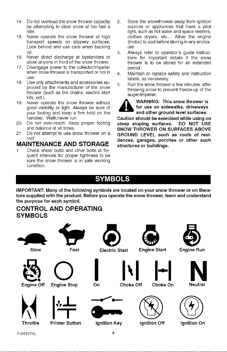
IMPORTANT: Many of the following symbols are located on your snow thrower or on litera-
ture supplied with the product. Before you operate the snow thrower, learn and understand
the purpose for each symbol.
CONTROL AND OPERATING
SYMBOLS
Slow Fast Electric Start Engine Start Engine Run
I H N
Engine Off Engine Stop On Choke Off Choke On Neutral
I''J-
Throttle Primer Button Ignition Key
F-041074L 4
®@
Ignition Off Ignition On
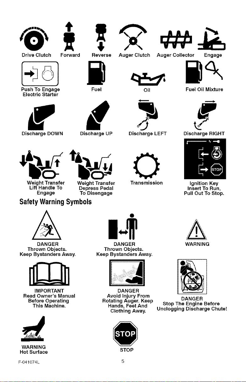
Drive Clutch Forward
Reverse Auger Clutch Auger Collector Engage
Push To Engage
Electric Starter
Discharge DOWN
Fuel Oil Fuel Oil Mixture
Discharge UP Discharge LEFT Discharge RIGHT
(.m
Weight Transfer Weight Transfer Transmission Ignition Key
Lift Handle To Depress Pedal Insert To Run,
Engage To Disengage Pull Out To Stop.
Safety WarningSymbols
DANGER DANGER WARNING
Thrown Objects. Thrown Objects.
Keep Bystanders Away. Keep Bystanders Away.
L_3
IMPORTANT DANGER
Read Owner's Manual
Before Operating
This Machine.
WARNING
Hot Surface
F-O41074L 5
Avoid Injury From
Rotating Auger. Keep
Hands, Feet And
Clothing Away.
DANGER
Stop The Engine Before
Unclogging Discharge Chute!
STOP
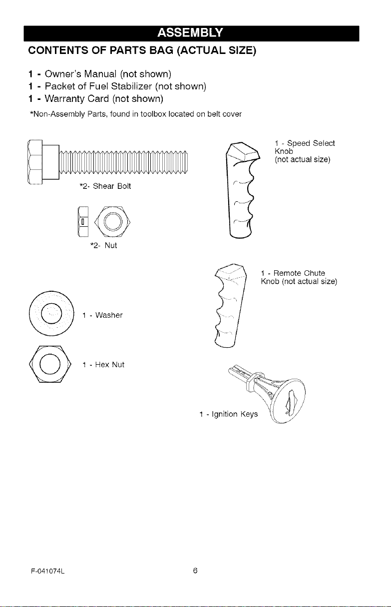
CONTENTS OF PARTS BAG (ACTUAL SIZE)
1 - Owner's Manual (not shown)
1 - Packet of Fuel Stabilizer (not shown)
1 - Warranty Card (not shown)
*Non-Assembly Parts, foundintoolboxlocatedon beltcover
1 - Washer
1 - Speed Select
_ Knob
(not actual size)
1 - Remote Chute
Knob (not actual size)
©
F-041074L 6
1 - Hex Nut
_hb ARNING: Always wear
thrower.
TOOLS REQUIRED FOR
ASSEMBLY
1 - Knife to cut carton
2 - 1/2 inch wrenches
2 - 9/16 inch wrenches
2 - 3/4 inch wrenches
1 - Pliers (to spread cotter pin)
1 - Screwdriver
1 - Measuring tape or ruler
safety glasses or eye shields
while assembling snow
(or adjustable wrenches)
(or adjustable wrenches)
(or adjustable wrenches)
/'-"-4
o
Figure 1
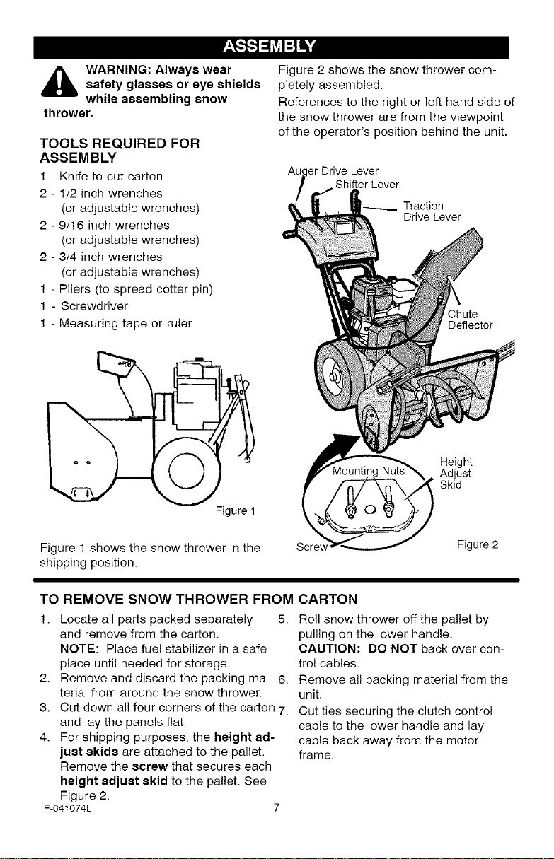
Figure 2 shows the snow thrower com-
pletely assembled.
References to the right or left hand side of
the snow thrower are from the viewpoint
of the operator's position behind the unit.
_r Drive Lever
Shifter Lever
Traction
Drive Lever
Chute
Deflector
Height
Adjust
Skid
Figure 1 shows the snow thrower in the
shipping position.
TO REMOVE SNOW THROWER FROM
1. Locate all parts packed separately 5.
and remove from the carton.
NOTE: Place fuel stabilizer in a safe
place until needed for storage.
2. Remove and discard the packing ma- 6.
terial from around the snow thrower.
3. Cut down all four corners of the carton 7.
and lay the panels flat.
4. For shipping purposes, the height ad-
just skids are attached to the pallet.
Remove the screw that secures each
height adjust skid to the pallet. See
Figure 2.
F-O41074L 7
Figure 2
CARTON
Roll snow thrower off the pallet by
pulling on the lower handle.
CAUTION: DO NOT back over con-
trol cables.
Remove all packing material from the
unit.
Cut ties securing the clutch control
cable to the lower handle and lay
cable back away from the motor
frame.
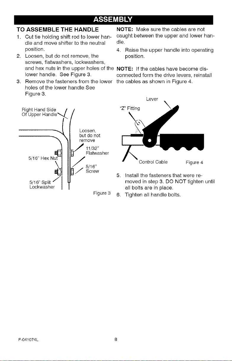
TOASSEMBLETHEHANDLE
1. Cuttieholdingshiftrodtolowerhan-
dleandmoveshiftertotheneutral
position.
2. Loosen,butdonotremove,the
NOTE:Makesurethecablesarenot
caughtbetweentheupperandlowerhan-
dle.
4. Raisetheupperhandleintooperating
position.
screws,flatwashers,Iockwashers,
and hex nuts in the upper holes of the NOTE: If the cables have become dis-
lower handle. See Figure 3. connected form the drive levers, reinstall
Remove the fasteners from the lower the cables as shown in Figure 4.
holes of the lower handle See
Figure 3.
Right Hand Side
Of Upper Handle_
"Z" Fitting X
Lever
//
but do not
t Loosen,
-h
5/16" Hex Nut_
remove
/ 111/a3t2"asher
Control Cable Figure 4
5/16" Split _
Lockwasher
Figure 3
F-O41074L 8
5. install the fasteners that were re-
moved in step 3. DO NOT tighten until
all bolts are in place.
6. Tighten all handle bolts.
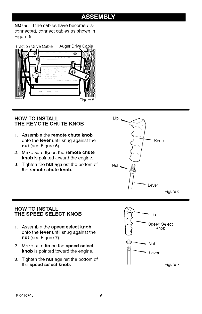
NOTE: If the cables have become dis-
connected, connect cables as shown in
Figure 5.
Traction Drive Cable Auger Drive Cable
Figure 5 =
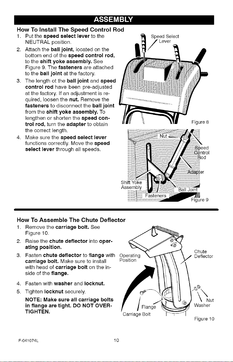
HOW TO INSTALL
THE REMOTE CHUTE KNOB
1. Assemble the remote chute knob
onto the lever until snug against the
nut (see Figure 6).
2. Make sure lip on the remote chute
knob is pointed toward the engine.
3. Tighten the nut against the bottom of
the remote chute knob.
HOW TO INSTALL
THE SPEED SELECT KNOB
1. Assemble the speed select knob
onto the lever until snug against the
nut (see Figure 7).
2. Make sure lip on the speed select
knob is pointed toward the engine.
3. Tighten the nut against the bottom of
the speed select knob.
Lip _.
Nut
i1--'-----_ Lever
_ Lip
@ _ Nut
i
_ Figure 7
Knob
Figure 6
Speed Select
Knob
Lever
F-041074L 9
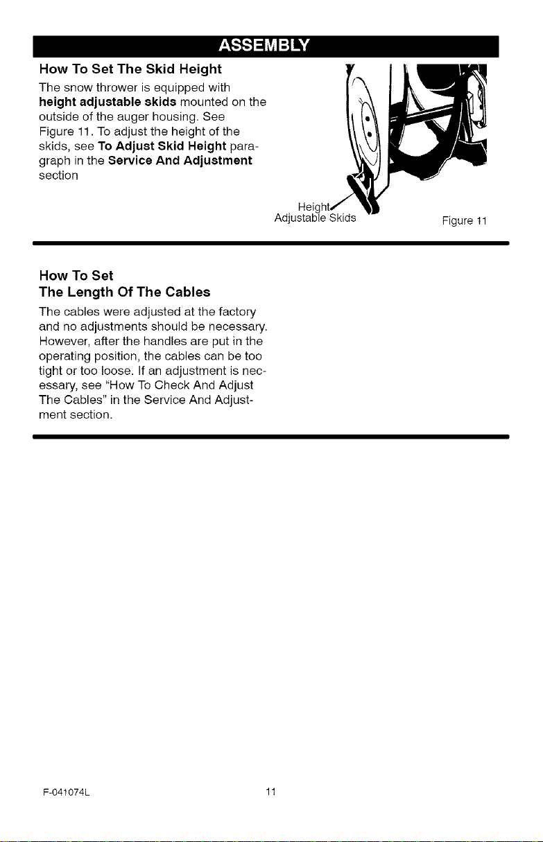
How To Install The Speed Control Rod
1. Put the speed select lever to the
NEUTRAL position.
2. Attach the ball joint, located on the
bottom end of the speed control rod,
to the shift yoke assembly, See
Figure 9. The fasteners are attached
to the ball joint at the factory.
3. The length ot the ball joint and speed
control rod have been pre-adjusted
at the factory. If an adjustment is re-
quired, loosen the nut. Remove the
fasteners to disconnect the ball joint
from the shift yoke assembly. To
lengthen or shorten the speed con-
trol rod, turn the adapter to obtain
the correct length.
4. Make sure the speed select lever
functions correctly. Move the speed
select lever through all speeds.
Shift
Assembly
Speed Select
Lever
Figure 8
Ball Joint
How To Assemble The Chute Deflector
1. Remove the carriage bolt. See
Figure 10.
2. Raise the chute deflector into oper-
ating position.
3. Fasten chute deflector to flange with Operating
carriage bolt. Make sure to install Position
with head of carriage bolt on the in-
side of the flange.
4.
Fasten with washer and Iocknut.
5.
Tighten Iocknut securely.
NOTE: Make sure all carriage bolts
in flange are tight. DO NOT OVER-
TIGHTEN.
F-041074L 10
Carriage Bolt
Chute
Deflector
Nut
Washer
Figure 10
How To Set The Skid Height
The snow thrower is equipped with
height adjustable skids mounted on the
outside of the auger housing. See
Figure 11. To adjust the height of the
skids, see To Adjust Skid Height para-
graph in the Service And Adjustment
section
How To Set
The Length Of The Cables
The cables were adjusted at the factory
and no adjustments should be necessary.
However, after the handles are put in the
operating position, the cables can be too
tight or too loose. If an adjustment is nec-
essary, see "How To Check And Adjust
The Cables" in the Service And Adjust-
ment section.
Adj
Heie
Figure 11
F-O41074L 11
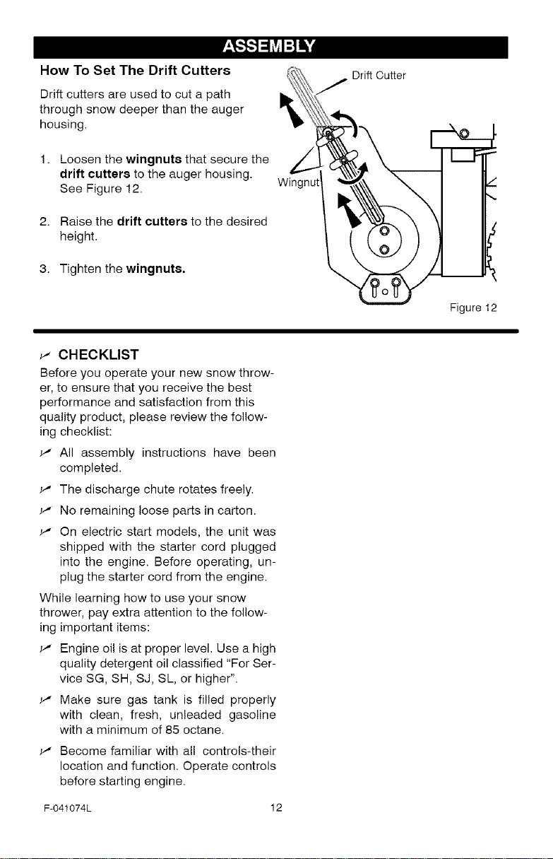
How To Set The Drift Cutters
Drift cutters are used to cut a path
through snow deeper than the auger
housing.
1. Loosen the wingnuts that secure the
drift cutters to the auger housing.
See Figure 12.
2. Raise the drift cutters to the desired
height.
3. Tighten the wingnuts.
_" CHECKLIST
Before you operate your new snow throw-
er, to ensure that you receive the best
performance and satisfaction from this
quality product, please review the follow-
ing checklist:
_' All assembly instructions have been
completed.
v' The discharge chute rotates freely.
v' No remaining loose parts in carton.
v' On electric start models, the unit was
shipped with the starter cord plugged
into the engine. Before operating, un-
plug the starter cord from the engine.
While learning how to use your snow
thrower, pay extra attention to the follow-
ing important items:
_' Engine oil is at proper level. Use a high
quality detergent oil classified "For Ser-
vice SG, SH, SJ, SL, or higher".
_' Make sure gas tank is filled properly
with clean, fresh, unleaded gasoline
with a minimum of 85 octane.
_' Become familiar with all controls-their
location and function. Operate controls
before starting engine.
F-041074L 12
Drift Cutter
Wingnut
Figure 12
[o_o)_
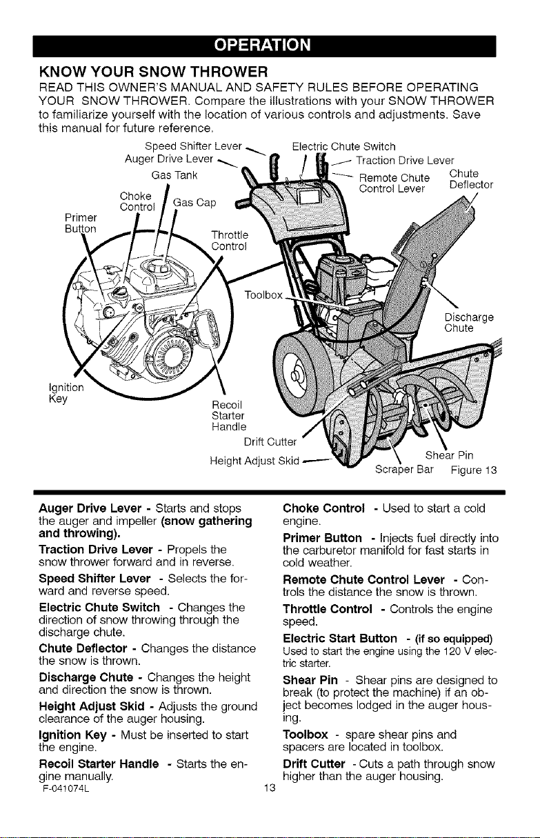
KNOW YOUR SNOW THROWER
READ THiS OWNER'S MANUAL AND SAFETY RULES BEFORE OPERATING
YOUR SNOW THROWER. Compare the illustrations with your SNOW THROWER
to familiarize yourself with the location of various controls and adjustments. Save
this manual for future reference.
Electric Chute Switch
Traction Drive Lever
Remote Chute Chute
Control Lever Deflector
Scraper Bar Figure 13
Discharge
Chute
Shear Pin
Primer
Button
Ignition
Key
Speed Shifter Lever.
Auger Drive Lever _.
Gas Tank
Choke
Control Cap
Recoil
Starter
Handle
Drift Cutter
Height Adjust Skid _--
Auger Drive Lever - Starts and stops
the auger and impeller (snow gathering
and throwing).
Traction Drive Lever - Propels the
snow thrower forward and in reverse.
Speed Shifter Lever - Selects the for-
ward and reverse speed.
Electric Chute Switch - Changes the
direction of snow throwing through the
discharge chute.
Chute Deflector - Changes the distance
the snow is thrown.
Discharge Chute - Changes the height
and direction the snow isthrown,
Height Adjust Skid - Adjusts the ground
clearance of the auger housing.
Ignition Key - Must be inserted to start
the engine.
Recoil Starter Handle - Starts the en-
gine manually.
F-041074L
Choke Control - Used to start a cold
engine.
Primer Button - Injects fuel directly into
the carburetor manifold for fast starts in
cold weather,
Remote Chute Control Lever - Con-
trols the distance the snow is thrown,
Throttle Control - Controls the engine
speed.
Electric Start Button - (if so equipped)
Usedto startthe engineusingthe 120V elec-
tricstarter.
Shear Pin - Shear pins are designed to
break (to protect the machine) if an ob-
iect becomes lodged in the auger hous-
ing.
Toolbox - spare shear pins and
spacers are located in toolbox.
Drift Cutter -Cuts a path through snow
higher than the auger housing.
13
[o_o)_
The operation of any snow thrower can
result in foreign objects being thrown
into the eyes, which can result in se-
vere eye damage. Always wear safety
glasses or eye shields while operating
the snow thrower.
We recommend standard safety
glasses or a wide vision safety mask for
over your glasses.
_b ARNING: Read Owner's
charge toward bystanders. Stop the
engine before unclogging discharge
chute or auger housing and before
leaving the machine.
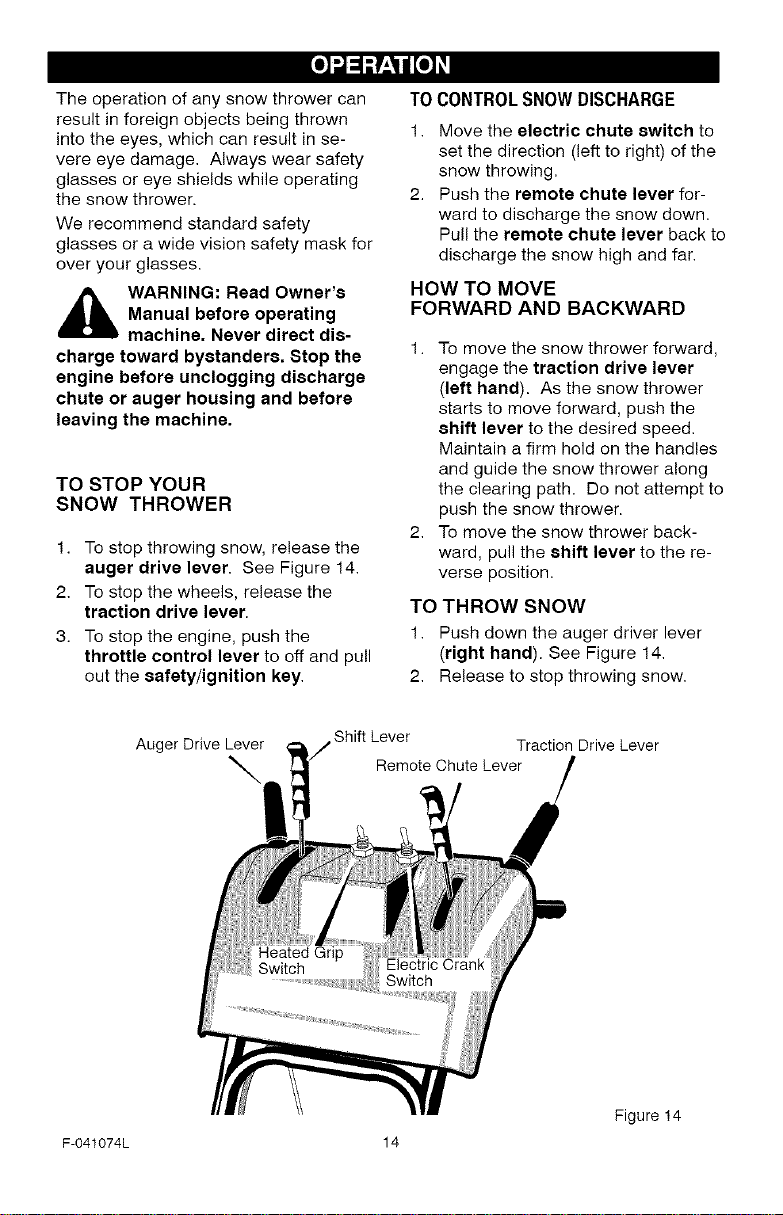
TO STOP YOUR
SNOW THROWER
1. To stop throwing snow, release the
2. To stop the wheels, release the
3. To stop the engine, push the
Manual before operating
machine. Never direct dis-
auger drive lever. See Figure 14.
traction drive lever.
throttle control lever to off and pull
out the safety/ignition key.
TO CONTROL SNOW DISCHARGE
1. Move the electric chute switch to
set the direction (left to right) of the
snow throwing.
2. Push the remote chute lever for-
ward to discharge the snow down.
Pull the remote chute lever back to
discharge the snow high and far.
HOW TO MOVE
FORWARD AND BACKWARD
1. To move the snow thrower forward,
engage the traction drive lever
(left hand). As the snow thrower
starts to move forward, push the
8hift lever to the desired speed.
Maintain a firm hold on the handles
and guide the snow thrower along
the clearing path. Do not attempt to
push the snow thrower.
2. To move the snow thrower back-
ward, pull the shift lever to the re-
verse position.
TO THROW SNOW
1. Push down the auger driver lever
(right hand). See Figure 14.
2. Release to stop throwing snow.
Auger Drive Lever
\
F-041074L 14
Shift Lever
Remote Chute Lever
Traction Drive Lever
Figure 14
[o_o)_
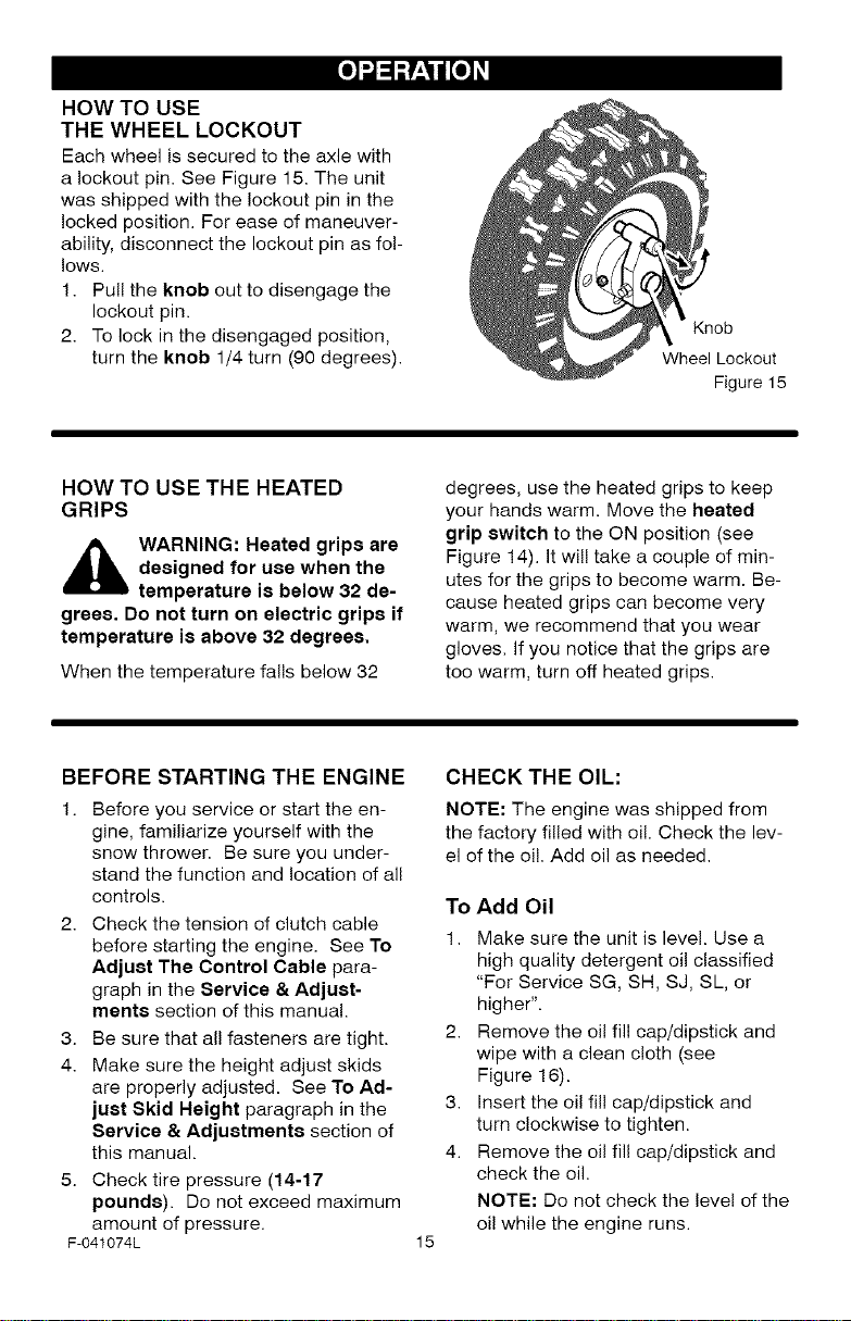
HOW TO USE
THE WHEEL LOCKOUT
Each wheel is secured to the axle with
a lockout pin. See Figure 15. The unit
was shipped with the lockout pin in the
locked position. For ease of maneuver-
ability, disconnect the lockout pin as fo!-
lows.
1. Pull the knob out to disengage the
lockout pin.
2. To lock in the disengaged position,
turn the knob 1/4 turn (90 degrees).
Knob
Wheel Lockout
Figure 15
HOW TO USE THE HEATED
GRIPS
,_ WARNING: Heated grips are
grees. Do not turn on electric grips if
temperature is above 32 degrees.
When the temperature falls below 32
designed for use when the
temperature is below 32 de-
BEFORE STARTING THE ENGINE
1. Before you service or start the en-
gine, familiarize yourself with the
snow thrower. Be sure you under-
stand the function and location of all
controls.
2. Check the tension of clutch cable
before starting the engine. See To
Adjust The Control Cable para-
graph in the Service & Adjust-
ments section of this manual.
3. Be sure that all fasteners are tight.
4. Make sure the height adjust skids
are properly adjusted. See To Ad-
just Skid Height paragraph in the
Service & Adjustments section of
this manual.
5. Check tire pressure (14-17
pounds). Do not exceed maximum
amount of pressure.
F-041074L
degrees, use the heated grips to keep
your hands warm. Move the heated
grip switch to the ON position (see
Figure 14). It will take a couple of min-
utes for the grips to become warm. Be-
cause heated grips can become very
warm, we recommend that you wear
gloves. If you notice that the grips are
too warm, turn off heated grips.
CHECK THE OIL:
NOTE: The engine was shipped from
the factory filled with oil. Check the lev-
el of the oi!. Add oil as needed.
To Add Oil
1.
Make sure the unit is level. Use a
high quality detergent oil classified
"For Service SG, SH, SJ, SL, or
higher".
Remove the oil fill cap/dipstick and
wipe with a clean cloth (see
Figure 16).
3.
Insert the oil fill cap/dipstick and
turn clockwise to tighten.
4.
Remove the oil fill cap/dipstick and
check the oil.
NOTE: Do not check the level of the
oi! while the engine runs.
15
[o_o)_
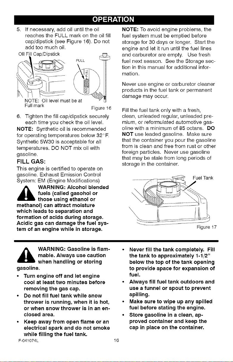
5. If necessary, add oil until the oil
reaches the FULL mark on the oil fill
cap/dipstick (see Figure 16). Do not
add too much oil.
OIIFIllCap/Dipstick
NOTE: Oil level must be at
Fullmark Figure 16
6. Tighten the fill cap/dipstick securely
each time you check the oil level.
NOTE; Synthetic oil is recommended
for operating temperatures below 32 °R
Synthetic 5W30 is acceptable for all
temperatures. DO NOT mix oi! with
gasoline.
FILL GAS:
This engine is certified to operate on
gasoline. Exhaust Emission Control
System: EM (Engine Modifications)
,_ WARNING: Alcohol blended
fuels (called gasohol or
those using ethanol or
methanol) can attract moisture
which leads to separation and
formation of acids during storage.
Acidic gas can damage the fuel sys-
tem of an engine while in storage.
NOTE: To avoid engine problems, the
fuel system must be emptied before
storage for 30 days or longer. Start the
engine and let it run until the fuel lines
and carburetor are empty. Use fresh
fuel next season. See the Storage sec-
tion in this manual for additional infor-
mation.
Never use engine or carburetor cleaner
products in the fuel tank or permanent
damage may occur.
Fill the fuel tank only with a fresh,
clean, unleaded regular, unleaded pre-
mium, or reformulated automotive gas-
oline with a minimum of 85 octans. DO
NOT use leaded gasoline. Make sure
that the container you pour the gasoline
from is clean and free from rust or other
foreign particles. Never use gasoline
that may be stale from long periods of
storage in the container.
Fuel Tank
\
,_ WARNING: Gasoline is flam-
mable. Always use caution
when handling or storing
gasoline.
• Turn engine off and let engine
cool at least two minutes before
removing the gas cap.
• Do not fill fuel tank while snow
thrower is running, when it is hot,
or when snow thrower is in an en-
closed area.
• Keep away from open flame or an
electrical spark and do not smoke
while filling the fuel tank.
F-041074L
• Never fill the tank completely. Fill
the tank to approximately 1-1/2"
below the top of the tank opening
to provide space for expansion of
fuel.
• Always fill fuel tank outdoors and
use a funnel or spout to prevent
spilling.
• Make sure to wipe up any spilled
fuel before stating the engine.
• Store gasoline in a clean, ap-
proved container and keep the
cap in place on the container.
16
[o_o)_
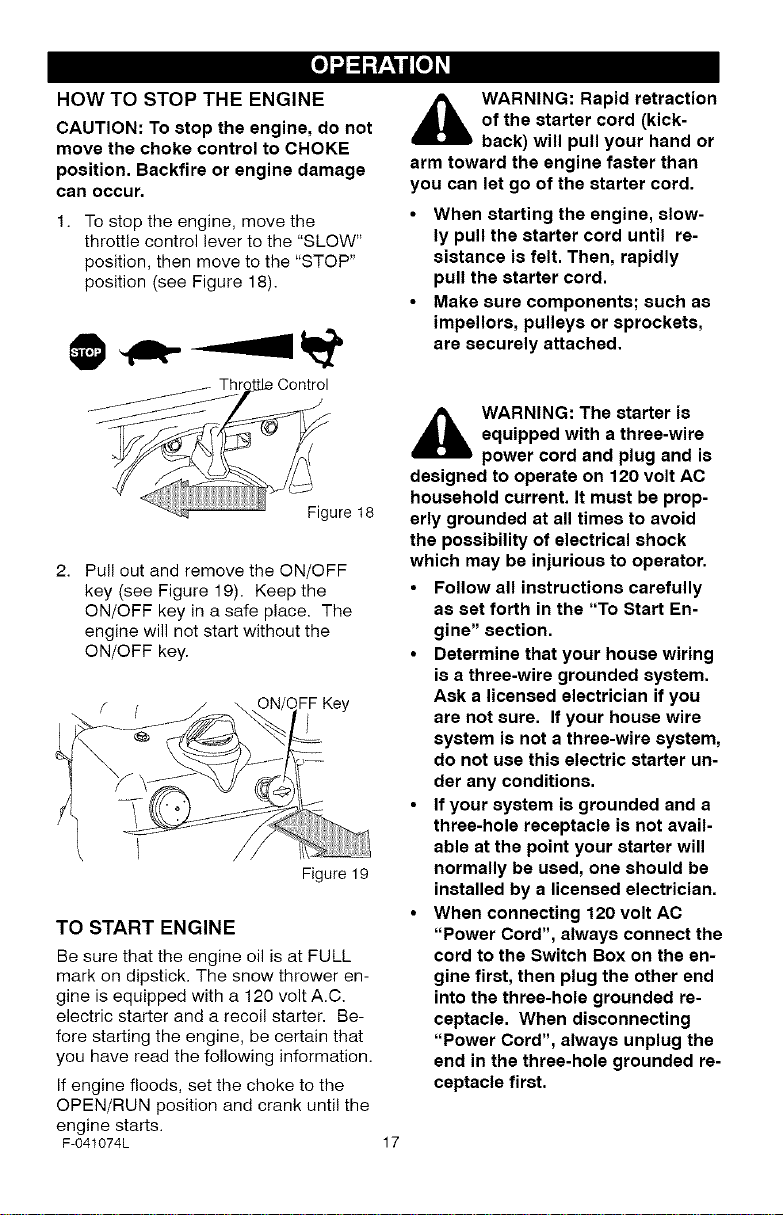
HOW TO STOP THE ENGINE
CAUTION: To stop the engine, do not
move the choke control to CHOKE
position. Backfire or engine damage
can occur.
1. To stop the engine, move the
throttle control lever to the "SLOW"
position, then move to the "STOP"
position (see Figure 18).
A ARNING: Rapid retraction
of the starter cord (kick-
back) will pull your hand or
arm toward the engine faster than
you can let go of the starter cord.
• When starting the engine, slow-
ly pull the starter cord until re-
sistance is felt. Then, rapidly
pull the starter cord.
• Make sure components; such as
impellors, pulleys or sprockets,
are securely attached.
Figure 18
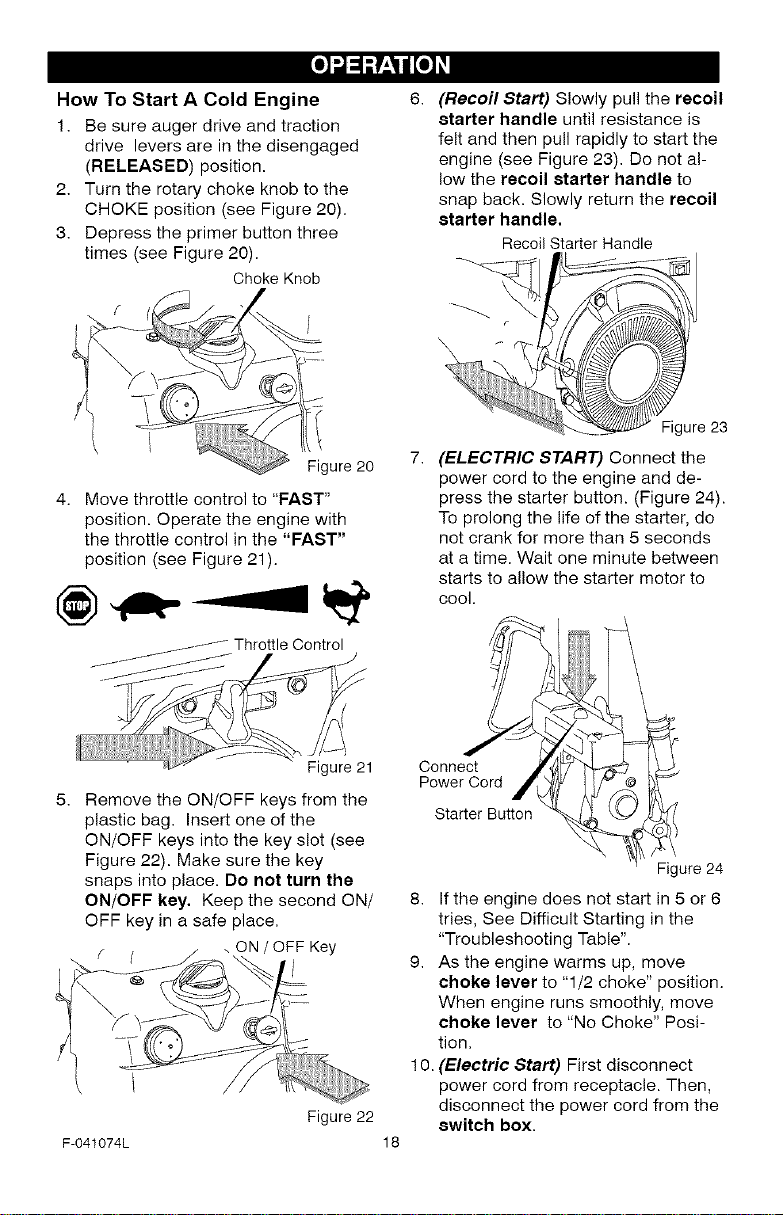
Pull out and remove the ON/OFF
key (see Figure 19). Keep the
ON/OFF key in a safe place. The
engine will not start without the
ON/OFF key.
FF Key
Figure 19
TO START ENGINE
Be sure that the engine oil is at FULL
mark on dipstick. The snow thrower en-
gine is equipped with a 120 volt A.C.
electric starter and a recoil starter. Be-
fore starting the engine, be certain that
you have read the following information.
If engine floods, set the choke to the
OPEN/RUN position and crank until the
engine starts.
F-041074L
A ARNING: The starter is
equipped with a three-wire
power cord and plug and is
designed to operate on 120 volt AC
household current. It must be prop-
erly grounded at all times to avoid
the possibility of electrical shock
which may be injurious to operator.
• Follow all instructions carefully
as set forth in the "To Start En-
gine" section.
• Determine that your house wiring
is a three-wire grounded system.
Ask a licensed electrician if you
are not sure. If your house wire
system is not a three-wire system,
do not use this electric starter un-
der any conditions.
• If your system is grounded and a
three-hole receptacle is not avail-
able at the point your starter will
normally be used, one should be
installed by a licensed electrician.
• When connecting 120 volt AC
"Power Cord", always connect the
cord to the Switch Box on the en-
gine first, then plug the other end
into the three-hole grounded re-
ceptacle. When disconnecting
"Power Cord", always unplug the
end in the three-hole grounded re-
ceptacle first.
17
[o_o)_
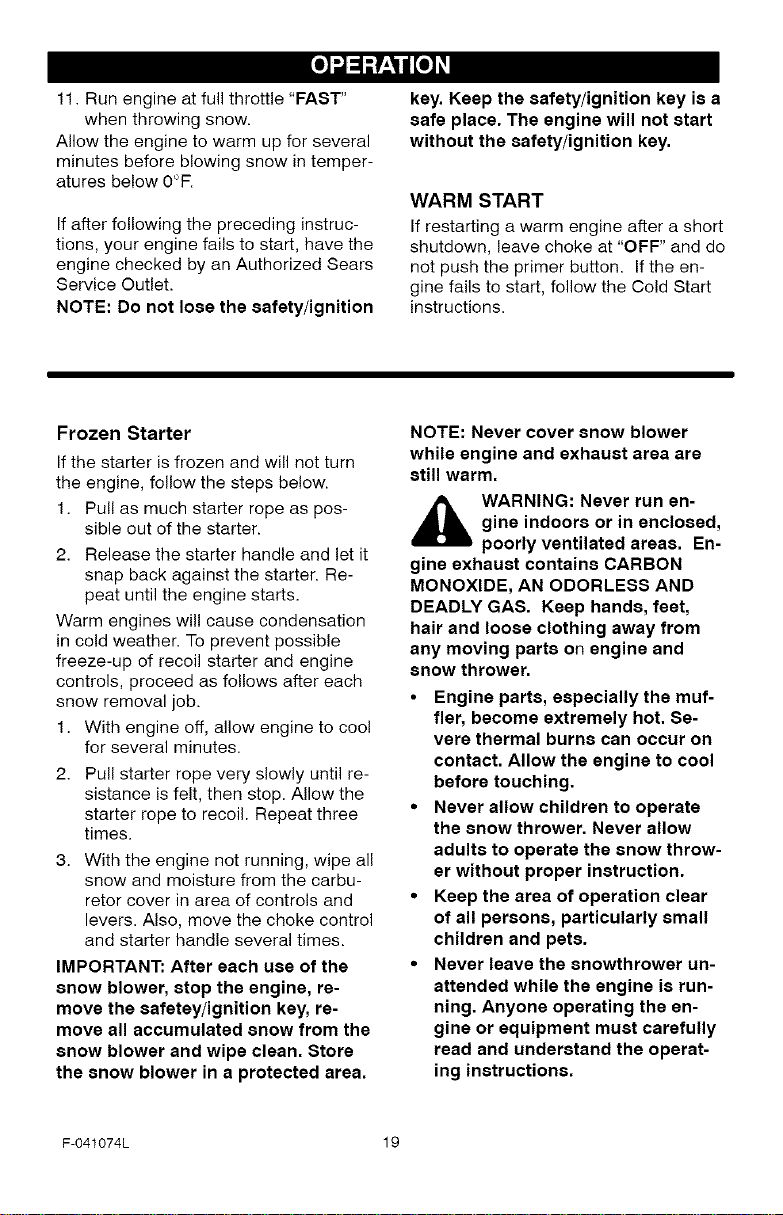
How To Start A Cold Engine
1. Be sure auger drive and traction
drive levers are in the disengaged
(RELEASED) position.
2. Turn the rotary choke knob to the
CHOKE position (see Figure 20).
3. Depress the primer button three
times (see Figure 20). _______
Choke Knob
ure 20 7. (ELECTRIC START) Connect the
4. Move throttle control to "FAST"
position. Operate the engine with
the throttle control in the "FAST"
position (see Figure 21).
(Recoil Start) Slowly pull the recoil
starter handle until resistance is
felt and then pull rapidly to start the
engine (see Figure 23). Do not al-
low the recoil starter handle to
snap back. Slowly return the recoil
starter handle.
Recoil StarterHandle
Figure 23
power cord to the engine and de-
press the starter button. (Figure 24).
To prolong the life of the starter, do
not crank for more than 5 seconds
at a time. Wait one minute between
starts to allow the starter motor to
cool.
Remove the ON/OFF keys from the
plastic bag. Insert one of the
ON/OFF keys into the key slot (see
Figure 22). Make sure the key
snaps into place. Do not turn the
ON/OFF key, Keep the second ON/
OFF key in a safe place.
ON / OFF Key
\\
F-041074L
Figure 21
Figure 22
Connect
Power Cord
Starter Button
Figure 24
8. If the engine does not start in 5 or 6
tries, See Difficult Starting in the
"Troubleshooting Table".
9. As the engine warms up, move
choke lever to "1/2 choke" position.
When engine runs smoothly, move
choke lever to "No Choke" Posi-
tion.
10. (Electric Start) First disconnect
power cord from receptacle. Then,
disconnect the power cord from the
switch box.
18
[o_o)_
11. Run engine at full throttle "FAST"
when throwing snow.
Allow the engine to warm up for several
minutes before blowing snow in temper-
atures below 0°R
If after following the preceding instruc-
tions, your engine fails to start, have the
engine checked by an Authorized Sears
Service Outlet.
NOTE: Do not lose the safety/ignition
Frozen Starter
If the starter is frozen and will not turn
the engine, follow the steps below.
1. Pull as much starter rope as pos-
sible out of the starter.
2. Release the starter handle and let it
snap back against the starter. Re-
peat until the engine starts.
Warm engines will cause condensation
in cold weather. To prevent possible
freeze-up of recoil starter and engine
controls, proceed as follows after each
snow removal job.
1. With engine off, allow engine to coo!
for several minutes.
Pull starter rope very slowly until re-
sistance is felt, then stop. Allow the
starter rope to recoil. Repeat three
times.
With the engine not running, wipe all
snow and moisture from the carbu-
retor cover in area of controls and
levers. Also, move the choke control
and starter handle several times.
IMPORTANT: After each use of the
snow blower, stop the engine, re-
move the safeteyiignition key, re-
move all accumulated snow from the
snow blower and wipe clean. Store
the snow blower in a protected area.
key. Keep the safety/ignition key is a
safe place. The engine will not start
without the safety/ignition key.
WARM START
If restarting a warm engine after a short
shutdown, leave choke at "OFF" and do
not push the primer button. Ifthe en-
gine fails to start, follow the Cold Start
instructions.
NOTE: Never cover snow blower
while engine and exhaust area are
still warm.
_ WARNING: Never run en-
gine indoors or in enclosed,
poorly ventilated areas. En-
gine exhaust contains CARBON
MONOXIDE, AN ODORLESS AND
DEADLY GAS. Keep hands, feet,
hair and loose clothing away from
any moving parts on engine and
snow thrower.
• Engine parts, especially the muf-
fler, become extremely hot. Se-
vere thermal burns can occur on
contact. Allow the engine to cool
before touching.
• Never allow children to operate
the snow thrower. Never allow
adults to operate the snow throw-
er without proper instruction.
• Keep the area of operation clear
of all persons, particularly small
children and pets.
• Never leave the snowthrower un-
attended while the engine is run-
ning. Anyone operating the en-
gine or equipment must carefully
read and understand the operat-
ing instructions.
F-041074L 19
[o_o)_
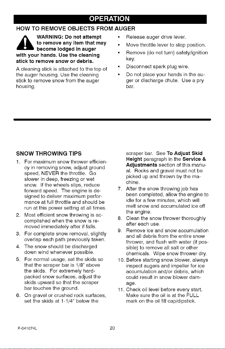
HOW TO REMOVE OBJECTS FROM AUGER
• Release auger drive lever.
_ ARNING: Do not attempt
with your hands. Use the cleaning
stick to remove snow or debris.
A cleaning stick is attached to the top of
the auger housing. Use the cleaning
stick to remove snow from the auger
housing.
to remove any item that may
become lodged in auger
• Move throttle lever to stop position.
• Remove (do not turn) safety/ignition
key.
• Disconnect spark plug wire.
• Do not place your hands in the au-
ger or discharge chute. Use a pry
bar.
SNOW THROWING TIPS
1. For maximum snow thrower efficien-
cy in removing snow, adjust ground
speed, NEVER the throttle. Go
slower in deep, freezing or wet
snow. If the wheels slips, reduce
forward speed. The engine is de-
signed to deliver maximum perfor-
mance at full throttle and should be
run at this power setting at all times.
2. Most efficient snow throwing is ac-
complished when the snow is re-
moved immediately after if falls.
3. For complete snow removal, slightly
overlap each path previously taken.
4. The snow should be discharged
down wind whenever possible.
5. For normal usage, set the skids so
that the scraper bar is 1/8" above
the skids. For extremely hard-
packed snow surfaces, adjust the
skids upward so that the scraper
bar touches the ground.
6. On gravel or crushed rock surfaces,
set the skids at 1-1/4" below the
scraper bar. See To Adjust Skid
Height paragraph in the Service &
Adjustments section of this manu-
al. Rocks and gravel must not be
picked up and thrown by the ma-
chine.
7. After the snow throwing job has
been completed, allow the engine to
idle for a few minutes, which will
melt snow and accumulated ice off
the engine.
8. Clean the snow thrower thoroughly
after each use.
9. Remove ice and snow accumulation
and all debris from the entire snow
thrower, and flush with water (if pos-
sible) to remove all salt or other
chemicals. Wipe snow thrower dry.
10. Before starting snow blower, always
inspect augers and impeller for ice
accumulation and/or debris, which
could result in snow blower dam-
age.
11. Check oil level before every start.
Make sure the oil is at the FULL
mark on the oil fil! cap/dipstick.
F-041074L 20
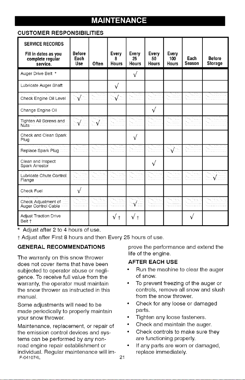
CUSTOMERRESPONSIBILITIES
SERVICE RECORDS
Fill in dates as you Before
complete regular Each
service. Use Often
Auger Drive Belt *
Lubricate Auger Shaft
Check Engine Oil Level
Change Engine Oil
Tighten A!! Screws and
Nuts
Check and Clean Spark
Plug
Clean and Inspect
Spark Arrestor
Check Fuel
Check Adjustment of I I I I I I
Auger Contro Cab e -
Every Every Every Every
8 25 50 100 Each Before
Hours Hours Hours Hours Season Storage
V
Adjust Traction Drive _ t _ t
Belt
* Adjust after 2 to 4 hours of use.
t Adjust after First 8 hours and then Every 25 hours of use.
GENERAL RECOMMENDATIONS
The warranty on this snow thrower
does not cover items that have been
subjected to operator abuse or negli-
gence. To receive full value from the
warranty, the operator must maintain
the snow thrower as instructed in this
manual.
Some adjustments will need to be
made periodically to properly maintain
your snow thrower.
Maintenance, replacement, or repair of
the emission control devices and sys-
tems can be performed by any non-
road engine repair establishment or
individual. Regular maintenance will im-
F-041074L
prove the performance and extend the
life of the engine.
AFTER EACH USE
• Run the machine to clear the auger
of snow.
• To prevent freezing of the auger or
controls, remove all snow and slush
from the snow thrower.
• Check for any loose or damaged
parts.
• Tighten any loose fasteners.
• Check and maintain the auger.
• Check controls to make sure they
are functioning properly.
• If any parts are worn or damaged,
replace immediately.
21
PRODUCT SPECIFICATIONS
HORSEPOWER 13 HP
DISPLACEMENT 20.85 cu. in.
BORE 83.82mm (3.300 in.)
STROKE 61.67mm (2.438 in.)
GASOLINE 4 quarts
CAPACITY (unleaded)
OIL CAPACITY
(28oz capacity)
5W30
SPARK PLUG: Gap0.030 in.
VALVE Intake: 0.004-0.006 in.
CLEARANCE: Exhaust: 0.009-0.011 in.
ARMATURE
AIR GAP: 0.010-0.014 in.
POWER RATINGS
The power ratings for an individual
engine model are initially developed by
starting with SAE (Society of Automo-
tive Engineers) code J1940 (Small
Engine Power & Torque Rating Proce-
dure) (Revision 2002-05). Given both
the wide array of products on which our
engines are placed, and the variety of
environmental issues applicable to
operating the equipment, it may be that
the engine you have purchased will not
develop the rated horsepower when
used in a piece of power equipment
(actual "on-site"power). This difference
is due to a variety of factors including,
but not limited to, the following: differ-
ences in altitude, temperature, baro-
metric pressure, humidity, fuel, engine
lubrication, maximum governed engine
speed, individual engine to engine
variability, design of the particular piece
of power equipment, the manner in
which the engine is operated, engine
run-in to reduce friction and clean out of
combustion chambers, adjustments to
the valves and carburetor, and other
factors. The power ratings may also be
adjusted based on comparisons to
other similar engines utilized in similar
applications, and will therefore not
necessarily match the values derived
using the foregoing codes.
SNOW THROWER
AUGER DRIVE BELT
Adjust the auger drive belt after the first
2 to 4 hours of use, again about mid-
season and twice each season thereaf-
ter (See "Belt Adjustment" in the
Service and Adjustment section).
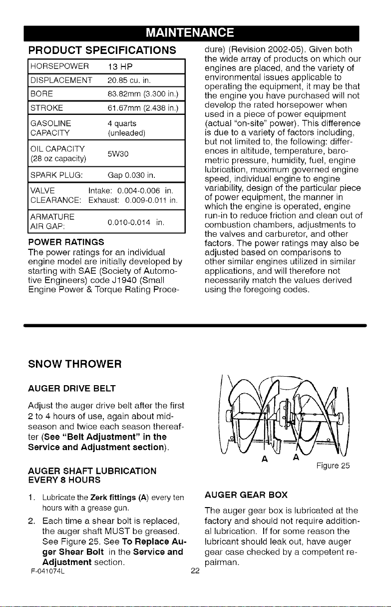
AUGER SHAFT LUBRICATION
EVERY 8 HOURS
1. Lubricate the Zerk fittings (A) every ten
hours with a grease gun.
2. Each time a shear bolt is replaced,
the auger shaft MUST be greased.
See Figure 25. See To Replace Au-
ger Shear Bolt in the Service and
Adjuetment section.
F-041074L
A
Figure 25
AUGER GEAR BOX
The auger gear box is lubricated at the
factory and should not require addition-
al lubrication. If for some reason the
lubricant should leak out, have auger
gear case checked by a competent re-
pairman.
22
ENGINE
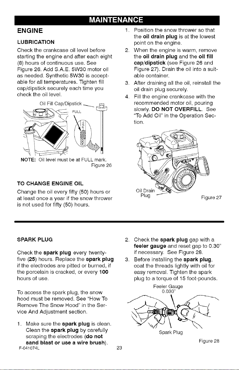
LUBRICATION
Check the crankcase oil level before
starting the engine and after each eight
(8) hours of continuous use. See
Figure 26. Add S.A.E. 5W30 motor oil
as needed. Synthetic 5W30 is accept-
able for all temperatures. Tighten fill
cap/dipstick securely each time you
check the oil level.
Oil Fill Cap/Dipstick_
FULL
NOTE: Oil level must be at FULL mark.
Figure 26
TO CHANGE ENGINE OIL
Change the oil every fifty (50) hours or
at least once a year if the snow thrower
is not used for fifty (50) hours.
1. Position the snow thrower so that
the oil drain plug is at the lowest
point on the engine.
2. When the engine is warm, remove
the oil drain plug and the oil fill
cap/dipstick (see Figure 26 and
Figure 27). Drain the oi! into a suit-
able container.
3. After draining all the oil, reinstall the
oil drain plug securely.
4. Fil! the engine crankcase with the
recommended motor oil, pouring
slowly. DO NOT OVERFILL. See
"To Add Oil" in the Operation Sec-
tion.
Oil Drain
Plug
Figure27
SPARK PLUG
Check the spark plug every twenty-
five (25) hours. Replace the spark plug
if the electrodes are pitted or burned, if
the porcelain is cracked, or every 100
hours of use.
To access the spark plug, the snow
hood must be removed. See "How To
Remove The Snow Hood" in the Ser-
vice And Adjustment section.
1. Make sure the spark plug is clean.
Clean the spark plug by carefully
scraping the electrodes (do not
sand blast or use a wire brush).
F-041074L
2. Check the spark plug gap with a
feeler gauge and reset gap to 0.30"
if necessary. See Figure 28.
3. Before installing the spark plug,
coat the threads lightly with oil for
easy removal. Tighten the spark
plug to a torque of 15 foot-pounds.
Feeler Gauge
0.030"
Spark Plug
23
Figure 28
_b ARNING: Always discon-
nect the spark plug wire and
place it where it cannot
make contact with spark plug to pre-
vent accidental starting when mak-
ing any adjustments or repairs.
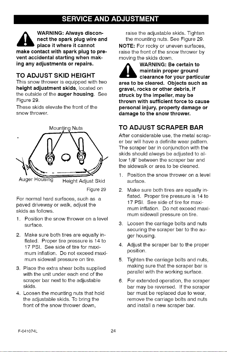
TO ADJUST SKID HEIGHT
This snow thrower is equipped with two
height adjustment skids, located on
the outside of the auger housing. See
Figure 29.
These skids elevate the front of the
snow thrower.
raise the adjustable skids. Tighten
the mounting nuts. See Figure 29.
NOTE: For rocky or uneven surfaces,
raise the front of the snow thrower by
moving the skids down.
_k WARNING: Be certain to
maintain proper ground
clearance for your particular
area to be cleared. Objects such as
gravel, rocks or other debris, if
struck by the impeller, may be
thrown with sufficient force to cause
personal injury, property damage or
damage to the snow thrower.
Mountinc Nuts
0
Au( g Height Adjust Skid
Figure 29
For normal hard surfaces, such as a
paved driveway or walk, adjust the
skids as follows.
1. Position the snow thrower on a level
surface.
2. Make sure both tires are equally in-
flated. Proper tire pressure is 14 to
17 PSI. See side of tire for maxi-
mum inflation. Do not exceed maxi-
mum sidewall pressure on tire.
3. Place the extra shear bolts supplied
with the unit under each end of the
scraper bar next to the adjustable
skids.
4. Loosen the mounting nuts that hold
the adjustable skids. To bring the
front of the snow thrower down,
TO ADJUST SCRAPER BAR
After considerable use, the metal scrap-
er bar will have a definite wear pattern.
The scraper bar in conjunction with the
skids should always be adjusted to al-
low 1/8" between the scraper bar and
the sidewalk or area to be cleaned.
1. Position the snow thrower on a level
surface,
2. Make sure both tires are equally in-
flated. Proper tire pressure is 14 to
17 PSI. See side of tire for maxi-
mum inflation. Do not exceed maxi-
mum sidewall pressure on tire.
3. Loosen the carriage bolts and nuts
securing the scraper bar to the au-
ger housing.
4. Adjust the scraper bar to the proper
position.
5. Tighten the carriage bolts and nuts,
making sure that the scraper bar is
parallel with the working surface.
6. For extended operation, the scraper
bar may be reversed. If the scraper
bar must be replaced due to wear,
remove the carriage bolts and nuts
and install a new scraper bar.
F-041074L 24
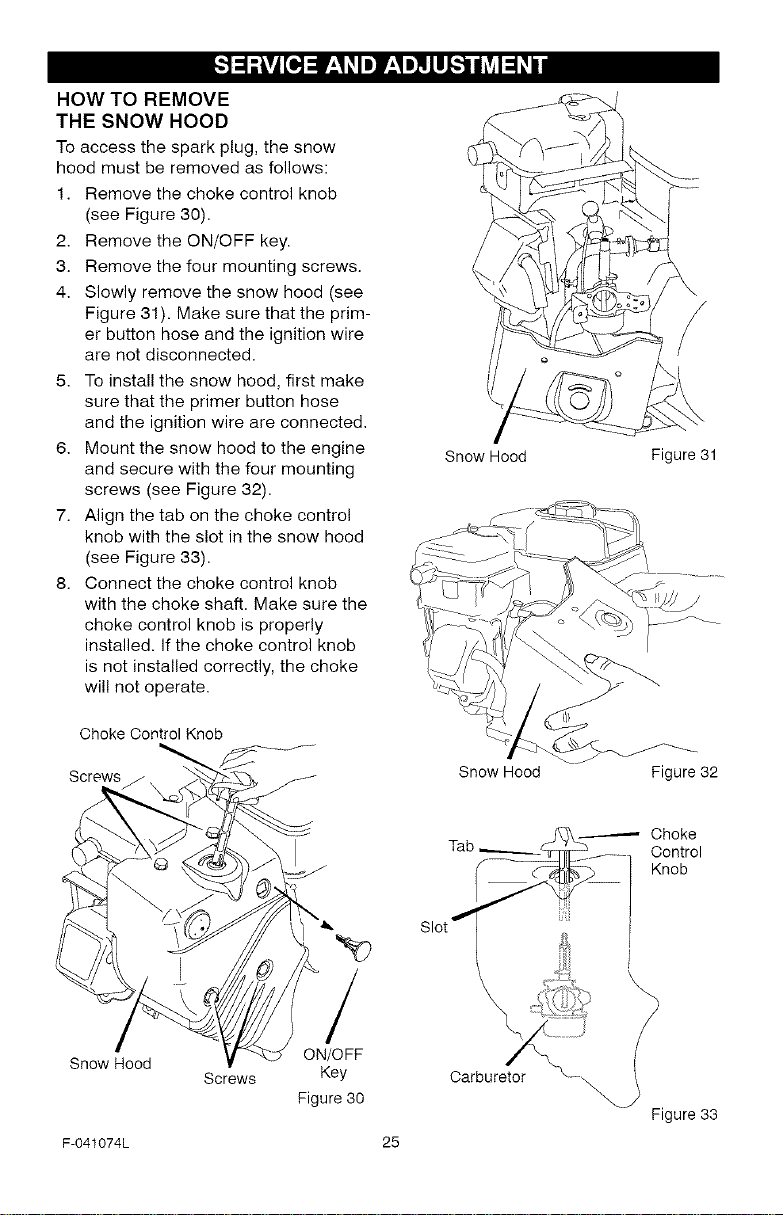
HOW TO REMOVE
THE SNOW HOOD
To access the spark plug, the snow
hood must be removed as follows:
1. Remove the choke control knob
(see Figure 30).
2. Remove the ON/OFF key.
3. Remove the four mounting screws.
4. Slowly remove the snow hood (see
Figure 31). Make sure that the prim-
er button hose and the ignition wire
are not disconnected.
5. To install the snow hood, first make
sure that the primer button hose
and the ignition wire are connected.
6. Mount the snow hood to the engine
and secure with the four mounting
screws (see Figure 32).
7. Align the tab on the choke control
knob with the slot in the snow hood
(see Figure 33).
8. Connect the choke control knob
with the choke shaft. Make sure the
choke control knob is properly
installed, if the choke control knob
is not installed correctly, the choke
will not operate.
, 4s
Snow Hood
/
\E
Figure31
Choke Control Knob
Screws
Snow Hood
F-041074L
Screws
/
ON/OFF
Key
Figure30
Snow Hood
Carburetor
25
Figure 32
Choke
Control
Knob
Figure33
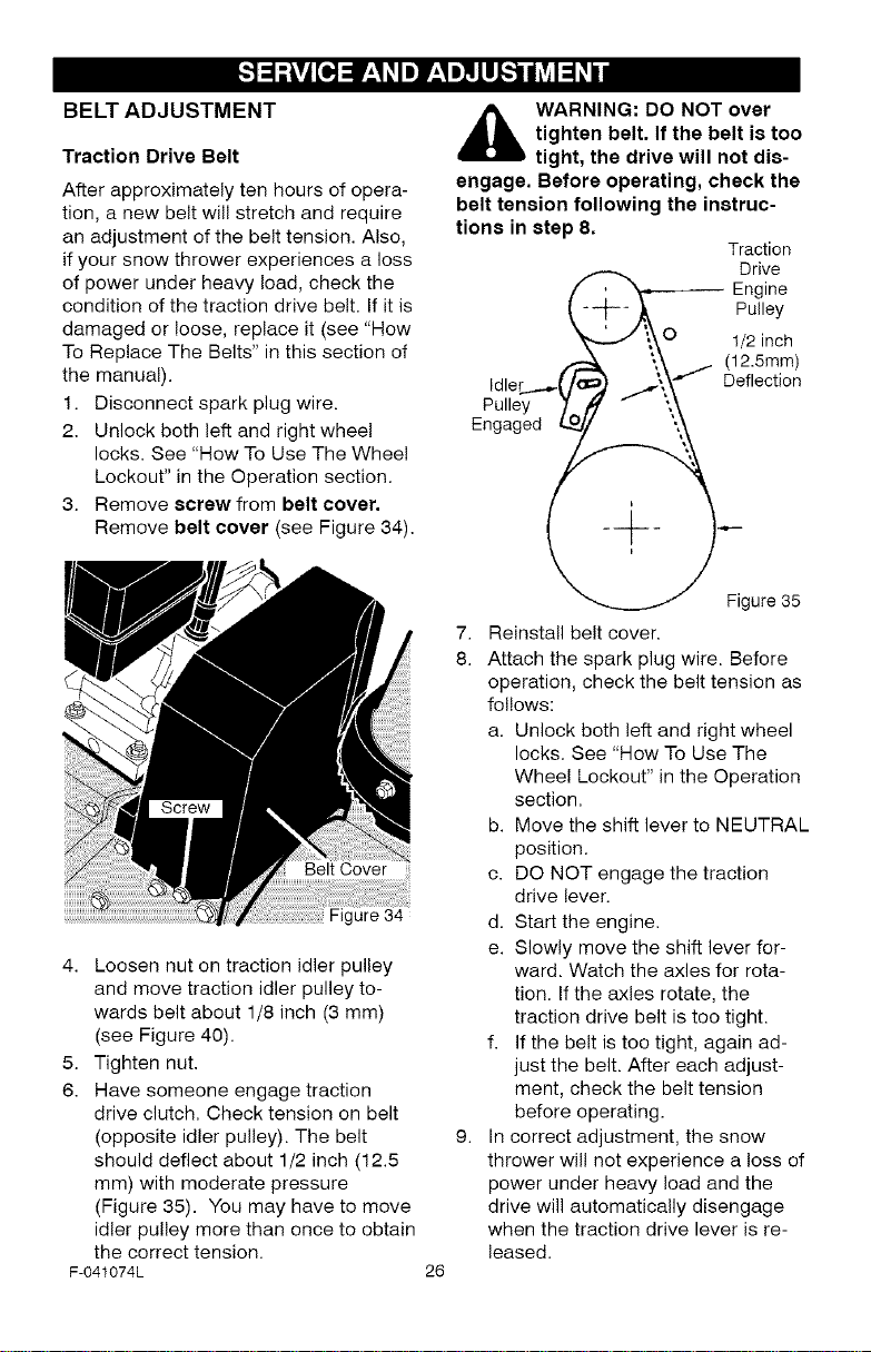
BELT ADJUSTMENT
Traction Drive Belt
After approximately ten hours of opera-
tion, a new belt will stretch and require
an adjustment of the belt tension. Also,
if your snow thrower experiences a loss
of power under heavy load, check the
condition of the traction drive belt. If it is
damaged or loose, replace it (see "How
To Replace The Belts" in this section of
the manual).
1. Disconnect spark plug wire.
2. Unlock both left and right wheel
locks. See "How To Use The Wheel
Lockout" in the Operation section.
3. Remove screw from belt cover.
Remove belt cover (see Figure 34).
gure 34
4. Loosen nut on traction idler pulley
and move traction idler pulley to-
wards belt about 1/8 inch (3 mm)
(see Figure 40).
5. Tighten nut.
6. Have someone engage traction
drive clutch. Check tension on belt
(opposite idler pulley). The belt
should deflect about 1/2 inch (12.5
mm) with moderate pressure
(Figure 35). You may have to move
idler pulley more than once to obtain
the correct tension.
F-041074L
,_ WARNING: DO NOT over
engage. Before operating, check the
belt tension following the instruc-
tions in step 8.
7. Reinstall belt cover.
8. Attach the spark plug wire. Before
9. In correct adjustment, the snow
26
tighten belt. If the belt i8 too
tight, the drive will not dis-
f _ Engine
-/_1_ ,_ Pulley
, ./\\O 1/2 inch
/- ';,_ j (12.5mm)
Idler ...__/c ..._\\f"J Deflection
Pulley 7 " ',\
Engaged/._i __
_Figure 35
operation, check the belt tension as
follows:
a. Unlock both left and right wheel
locks. See "How To Use The
Wheel Lockout" in the Operation
section.
b. Move the shift lever to NEUTRAL
position.
c. DO NOT engage the traction
drive lever.
d. Start the engine.
e. Slowly move the shift lever for-
ward. Watch the axles for rota-
tion. If the axles rotate, the
traction drive belt is too tight.
f. If the belt is too tight, again ad-
just the belt. After each adjust-
ment, check the belt tension
before operating.
thrower will not experience a loss of
power under heavy load and the
drive will automatically disengage
when the traction drive lever is re-
leased.
Traction
Drive
[.,,."]_e,,_ r*..1ZIB]I'_"_
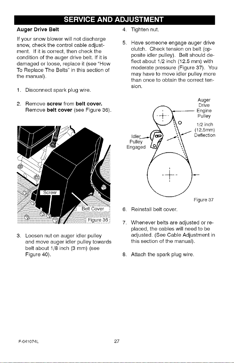
Auger Drive Belt
If your snow blower will not discharge
snow, check the control cable adjust-
ment. If it is correct, then check the
condition of the auger drive belt. If it is
damaged or loose, replace it (see "How
To Replace The Belts" in this section of
the manual).
1. Disconnect spark plug wire.
2. Remove screw from belt cover,
Remove belt cover (see Figure 36).
4.
Tighten nut.
5.
Have someone engage auger drive
clutch. Check tension on belt (op-
posite idler pulley). Belt should de-
flect about 1/2 inch (12.5 mm) with
moderate pressure (Figure 37). You
may have to move idler pulley more
than once to obtain the correct ten-
sion.
f _ Engine
k A Pu,ey
, J \\O 1/2 inch
idler_..._C F ..7\\f'f" Deflection
Pulley 70, " "_
Engaged _ ",,_
';,_ _ (12.5mm)
Auger
Drive
Belt Cover
ure 36
Loosen nut on auger idler pulley
and move auger idler pulley towards
belt about 1/8 inch (3 mm) (see
Figure 40).
F-041074L 27
6.
Reinstall belt cover.
7.
Whenever belts are adjusted or re-
placed, the cables will need to be
adjusted. (See Cable Adjustment in
this section of the manual).
8. Attach the spark plug wire.
Figure 37
HOW TO REPLACE THE BELTS
The drive belts are of special construc-
tion and must be replaced with original
equipment replacement belts available
from your nearest Sears service center.
Some steps require the assistance of a
second person.
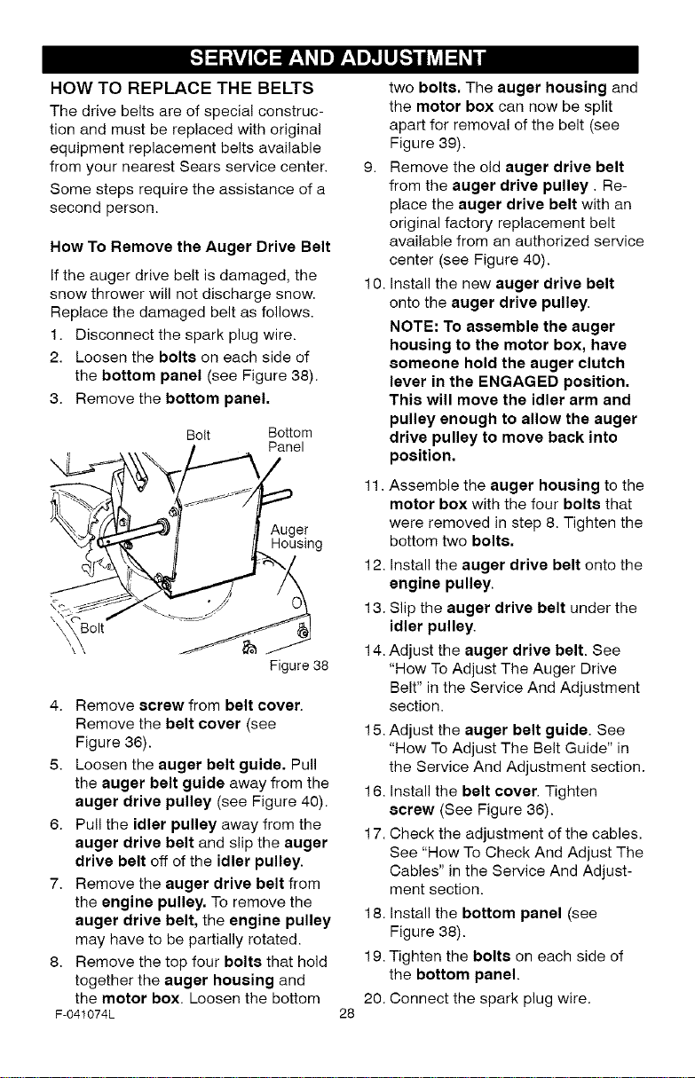
How To Remove the Auger Drive Belt
If the auger drive belt is damaged, the
snow thrower will not discharge snow.
Replace the damaged belt as follows.
1. Disconnect the spark plug wire.
2. Loosen the bolte on each side of
the bottom panel (see Figure 38).
3. Remove the bottom panel.
Bolt Bottom
Panel
Auger
Housing
olt
Figure38
4. Remove screw from belt cover.
Remove the belt cover (see
Figure 36).
5. Loosen the auger belt guide. Pull
the auger belt guide away from the
auger drive pulley (see Figure 40).
6. Pull the idler pulley away from the
auger drive belt and slip the auger
drive belt off of the idler pulley.
7. Remove the auger drive belt from
the engine pulley. To remove the
auger drive belt, the engine pulley
may have to be partially rotated.
8. Remove the top four bolts that hold
together the auger housing and
the motor box. Loosen the bottom
F-041074L
two bolts. The auger housing and
the motor box can now be split
apart for removal of the belt (see
Figure 39).
9. Remove the old auger drive belt
from the auger drive pulley. Re-
place the auger drive belt with an
original factory replacement belt
available from an authorized service
center (see Figure 40).
10. Install the new auger drive belt
onto the auger drive pulley.
NOTE: To assemble the auger
housing to the motor box, have
someone hold the auger clutch
lever in the ENGAGED position.
This will move the idler arm and
pulley enough to allow the auger
drive pulley to move back into
position.
11. Assemble the auger housing to the
motor box with the four bolts that
were removed in step 8. Tighten the
bottom two bolts.
12. Install the auger drive belt onto the
engine pulley.
13. Slip the auger drive belt under the
idler pulley.
14. Adjust the auger drive belt. See
"How ToAdjust The Auger Drive
Belt" in the Service And Adjustment
section.
15. Adjust the auger belt guide. See
"How ToAdjust The Belt Guide" in
the Service And Adjustment section.
16. Install the belt cover. Tighten
ecrew (See Figure 36).
17. Check the adjustment of the cables.
See "How To Check And Adjust The
Cables" in the Service And Adjust-
ment section.
18. Install the bottom panel (see
Figure 38).
19. Tighten the bolts on each side of
the bottom panel.
20. Connect the spark plug wire.
28
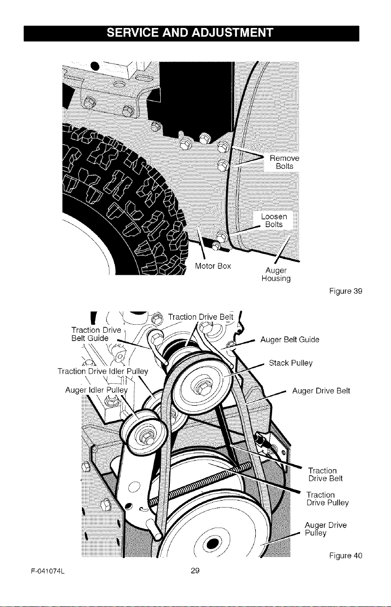
Remove
Bolts
Traction Drive
Belt Guide
Traction Drive Idler Pulley
Auger Idler Pulley
Motor Box
Auger
Housing
Figure 39
Auger Belt Guide
Stack Pulley
Auger Drive Belt
Traction
Drive Belt
Traction
Drive Pulley
Auger Drive
Pulley
F-041074L 29
Figure 40
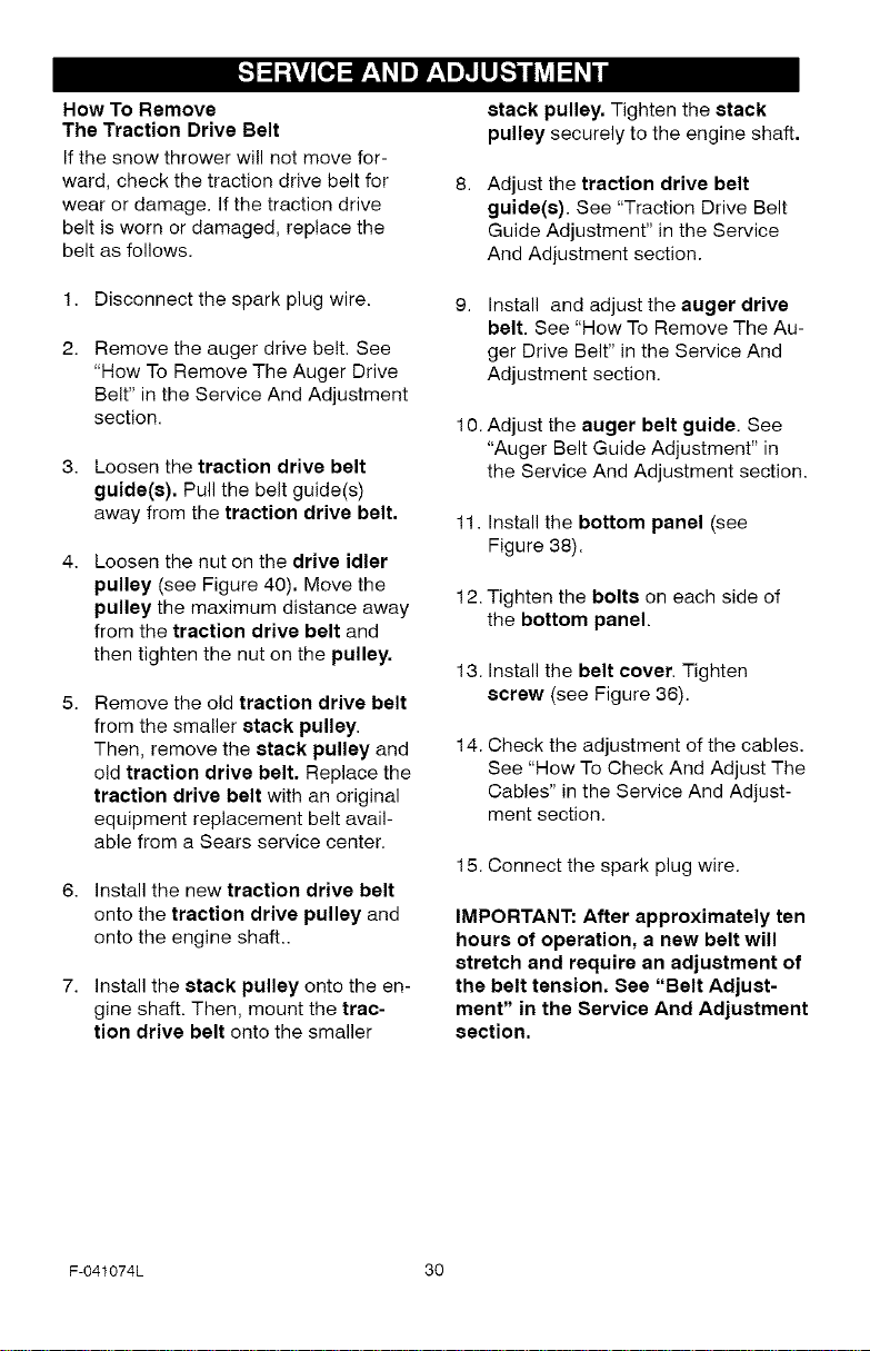
How To Remove
The Traction Drive Belt
If the snow thrower will not move for-
ward, check the traction drive belt for
wear or damage, if the traction drive
belt is worn or damaged, replace the
belt as follows.
stack pulley. Tighten the stack
pulley securely to the engine shaft.
Adjust the traction drive belt
guide(s). See "Traction Drive Belt
Guide Adjustment" in the Service
And Adjustment section.
1. Disconnect the spark plug wire.
Remove the auger drive belt. See
"How To Remove The Auger Drive
Belt" in the Service And Adjustment
section.
3. Loosen the traction drive belt
guide(s). Pull the belt guide(s)
away from the traction drive belt.
Loosen the nut on the drive idler
pulley (see Figure 40). Move the
pulley the maximum distance away
from the traction drive belt and
then tighten the nut on the pulley.
Remove the old traction drive belt
from the smaller stack pulley.
Then, remove the stack pulley and
old traction drive belt. Replace the
traction drive belt with an original
equipment replacement belt avail-
able from a Sears service center.
6. Install the new traction drive belt
onto the traction drive pulley and
onto the engine shaft..
7. Install the stack pulley onto the en-
gine shaft. Then, mount the trac-
tion drive belt onto the smaller
Install and adjust the auger drive
belt. See "How To Remove The Au-
ger Drive Belt" in the Service And
Adjustment section.
10. Adjust the auger belt guide. See
"Auger Belt Guide Adjustment" in
the Service And Adjustment section.
11. Install the bottom panel (see
Figure 38).
12. Tighten the bolts on each side of
the bottom panel.
13. Install the belt cover. Tighten
screw (see Figure 36).
14. Check the adjustment of the cables.
See "How To Check And Adjust The
Cables" in the Service And Adjust-
ment section.
15. Connect the spark plug wire.
IMPORTANT: After approximately ten
hours of operation, a new belt will
stretch and require an adjustment of
the belt tension. See "Belt Adjust-
ment" in the Service And Adjustment
section.
F-041074L 30
 Loading...