

Craftsman 536886540 Owner’s Manual
IMPORTANT MANUAL DO NOT THROW AWAY
OWNER'S
MANUAL
MODEL NO.
536.886540
Caution:
Read and Follow
All Safety Rules
and Instructions
Before Operating
This Equipment
®
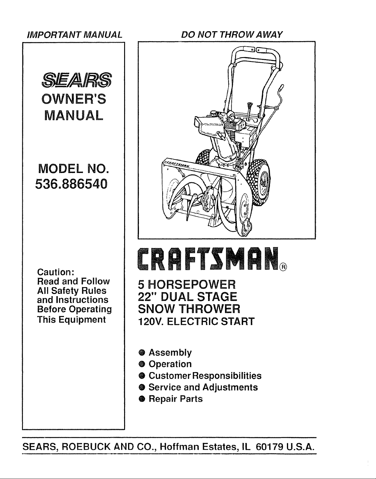
5 HORSEPOWER
22" DUAL STAGE
SNOW THROWER
120V. ELECTRIC START
® Assembly
O Operation
O Customer Responsibilities
• Service and Adjustments
® Repair Parts
SEARS, ROEBUCK AND CO., Hoffman Estates, IL 60179 U.S.A.
SAFETY RULES
& CAUTION: ALWAYS DISCONNECT SPARK PLUG WIRE AND &
PLACE WIRE WHERE IT CANNOT CONTACT SPARK PLUG
TO PREVENT ACCIDENTAL STARTING WHEN SETTING-UP,
TRANSPORTING, ADJUSTING OR MAKING REPAIRS.
IMPORTANT
SAFETY STANDARDS REQUIRE OPERATOR PRESENCE CONTROLS TO MINIMIZE THE
RISK OF INJURY.. YOUR SNOW THROWER IS EQUIPPED WITH SUCH CONTROLS. DO NOT
ATTEMPT TO DEFEAT THE FUNCTION OF THE OPERATOR PRESENCE CONTROL UNDER
ANY CIRCUMSTANCES.
TRAINING
1, Read the operator's manual carefully° Be
thoroughly familiar with the controls and the
proper use of the snow thrower. Know how to
stop the snow thrower and disengage the
controls quickly.
2o Never allowchildren to operate the snow thrower
and keep them away while it is operating Never
allow adults to operate the snow thrower without
proper instruction, Do not carry passengers.
3o Keep the area of operation clear of all persons,
particularly small children, and pets.
4_ Exercise caution to avoid slipping or falling,
especially when operating in reverse..
PREPARATION
1. Thoroughly inspect the area where the snow
thrower is to be used and remove all doormats,
sleds, boards, wires, and other foreign objects°
2. Disengage all clutches and shift into neutral
before starting the engine (motor).
3. Do not operate the snowthrower without wearing
adequate winter outer garments. Wear footwear
that will improve footing on slippery surfaces.
4. Handle fuel with care; it is highly flammable,
(a) Use an approved fuel container..
(b) Never remove fuel tank cap or add fuel to a
running engine or hot engine.
(c) Fill fuel tank outdoors with extreme care..
Never fill fuel tank indoor&
(d) Replace fuel tank cap securely and wipe up
spilled fuel.,
_e) Never store fuel or snow thrower with fuel in
the tank inside of a building where fumes may
reach an open flame or spark_
(f) Check fuel supply before each use, allowing
space for expansion as the heat of the engine
(motor) and/or sun can cause fuel to expand.
.
Use extension cords and receptacles as specified
by the manufacturer for all snow throwers with
electric drive motors or electric starting motors.
6. Adjust the snow thrower'height to clear gravel or
crushed rock surfaces.
7,, Never attempt to make any adjustments whilethe
engine (motor) is running (except when
specifically recommended bythe manufacturer)_
8. Let engine (motor) and snow thrower adjust to
outdoor temperatures before starting to clear
snow.
9. Always wear safety glasses or eye shields during
operation or while performing an adjustment or
repair to protect eyes from foreign objects that
may be thrown from the snow thrower.
OPERATION
1. Do not put hands or feet near' or under rotating
parts. Keep clear of the discharge opening at all
times_
2. Exercise extreme caution when operating on or
crossing gravel drives, walks, or roads. Stay alert
for hidden hazards or traffic.
After striking a foreign object, stop the engine
(motor), remove the wire from the spark plug,
disconnect the cord on electric motors,
thoroughly inspect the snow thrower for any
damage, and repair the damage before restarting
and operating the snow thrower.
4_
If the snow thrower should start to vibrate
abnormally, stop the (motor) and check
immediately for the cause° Vibration is generally
a warning of trouble.
5._ Stop the engine (motor) whenever you leave the
operating position, before unclogging the auger/
impeller housing or discharge guide, and when
making any repairs, adjustments, or inspections.
6. When cleaning, repairing, or inspecting, make
certain the auger/impeller and all moving parts
have stopped_ Disconnect the spark plug wire
and keep the wire away from the plug to prevent
accidental starting.
7. Take all possible precautions when leaving the
snow thrower unattended. Disengage the auger/
impeller, shift to neutral, stop engine, and
remove key..
SAFETY RULES
8, DO not run the engine indoors, except when starting
the engine and for transporting the snow thrower in
or out of the building. Open the outside doors;
exhaust fumes are dangerous (containing CARBON
MONOXIDE, an ODORLESS and DEADLY GAS)°
9o Do not clear snow across the face of slopes.
Exercise caution when changing direction on
slopes. Do not attempt to clear steep slopes_
10. Never operate the snow thrower without proper
guards, plates or other safety protective devices
in place..
1t. Never operate the snow thrower near glass
enclosures, automobiles, window wells,
drop-offs, and the like wit hour proper adjustment
of the snow discharge angle Keep children and
pets away.
12o Do not overload the machine capacity by
attempting to clear snow at too fast a rate.
13. Neveroperate the snow thrower at high transport
speeds on slippery surlaces. Look behind and
use care when backing.
14.. Never direct discharge at bystanders or allow
anyone in front of the snow thrower..
15. Disengage power to the auger/impeller when
snow thrower is transported or not in use.
16. Use only attachments and accessories approved
by the manufacturer of the snow thrower (such
as tire chains, electric start kitS, etc )
'17. Never operate the snow thrower without good
visibility or light,. Always be sure ot your footing,
and keep a firm hold on the handles Walk; never
run..
MAINTENANCEAND STORAGE
1.. Check shear bolts and other boils frequently for
improper tightness to be sure the snow thrower
is in sate working condition_
2o Never store the snow thrower with tuel in the fuel
tank inside a building where ignition sources are
present such as hot water and space heaters,
clothes dryers, and the like.. Allow the engine to
coot before storing in any enclosure..
3 Always refer to operator's manual instructions
for important details if the snow thrower is to be
stored tor an extended period,
4o Maintain or replace safety and instruction labels,
as necessary.
5,. Run the snow thrower a tew minutes after
throwing snow to prevent freeze-up of the auger/
impeller°
WARNING
This snow thrower is for use on sidewalks,
driveways, and other ground level surfaces.
CAUTION should be exercised while using on
steep sloping surfaces. DO NOT USE SNOW
THROWER ON SURFACES ABOVE GROUND
LEVEL such as roofs of residences, garages,
porches or other such structures or bulldingso
LOOK FOR THIS SYMBOL TO POINT OUT---]
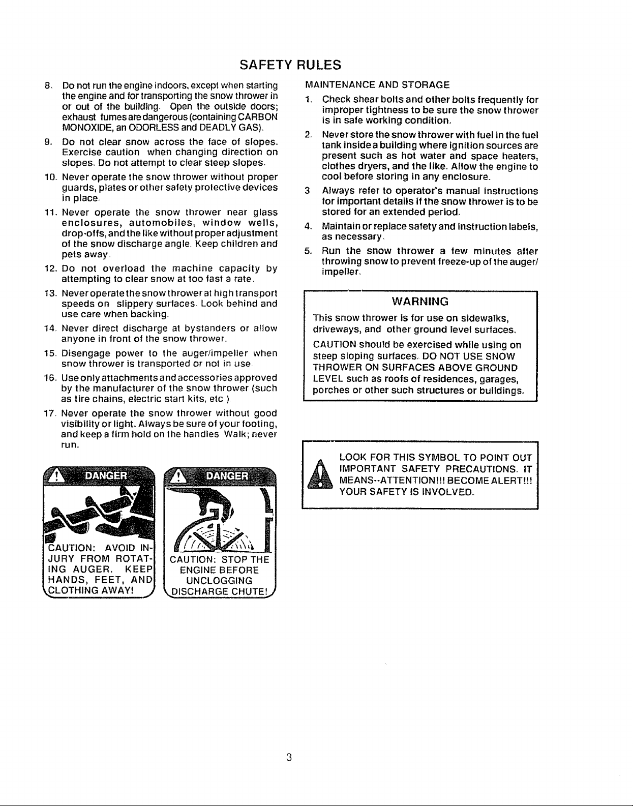
CAUTION:
ING AUGER,
_LOTH1NG AWAY!
DISCHARGE CHUTE!
_ IMPORTANT SAFETY PRECAUTIONS_ IT !
MEANS--ATTENTION!!! BECOME ALERT!!! _
YOUR SAFETY IS INVOLVED_ /
3
CONGRATULATIONS on your purchase of a Sears
Craftsman Snow Thrower It has been designed, engi-
neered and manufactured to give you the best possible
dependability and performance
Should you experience any problem you cannot easily
remedy, please contact your nearest Sears Service
Center/Department Sears has competent, wetHrained
technicians and the proper tools to service or repair this
unil
Please read and retain this manual The instruclions will
enable you Io assemble and maintain your snow thrower
]roperly, Always observe the "SAFETY RULES/
MODEL
NUMBER 536 886540
SERIAL
NUMBER
DATE OF
PURCHASE
THE MODEL AND SERIAL NUMBERS WILL BE
FOUND ON A DECAL ATTACHED TO THE REAR
OF THE SNOW THROWER HOUSING
YOU SHOULD RECORD BOTH SERIAL NUMBER
AND DATE OF PURCHASE AND KEEP IN A SAFE
PLACE FOR FUTURE REFERENCE
PRODUCT SPECIFICATIONS
HORSE POWER: 5 hp
DISPLACEMENT: 12.04
cu_ in.
GASOLINE CAPACITY: 2 quarts
Unleaded
OIL (21 oz. Capacity): SAE 5W-30
SPARK PL.UG :
(GAP .030 in.)
VALVE CLEARANCE: Intake: .010 In,
Champion
RJ19LM
Exhaust: .010 In.
MAINTENANCE AGREEMENT
A Sears Mainlenance Agreement is available on this
product Contact your nearest Sears Slore for details
CUSTOMER RESPONSIBILITIES
• Read and observe the safety rules
o Follow a regular schedule in maintaining, caring to_ and using your snow thrower
• Follow the instructions under "Customer Responsibilities and "Storage sections ot this owners manual
TWO YEAR LIMITED WARRANTY ON CRAFTSMAN
SNOW THROWER
For lwo years from the date of purchase, when this Craftsman Snow Thrower is maintained, lubricated
and tuned-up according to the instructions in the owner s manual, Sears will repair, free of charge, any
detecl in material and workmanship
1Ithis Craftsman Snow Thrower is used Ior commercial or renlat purposes, this warranty applies !or only
90 days from the date of purchase
This warranty does not cover the following:
,, Expendable ilems which become worn during normal use, such as spark plugs, drive belts and shear
pins
t Repairs necessary because ol operator abuse or negligence, including benl crankshalts and lhe lailure
to maintain the equipment according to the instructions contained in the owner's manual
WARRANTY SERVICE IS AVAILABLE BY RETURNING THE CRAFTSMAN SNOW THROWER TO THE
NEAREST SEARS SERVICE CENTER/DEPARTMENT IN THE UNITED STATES THIS WARRANTY
APPLIES ONLY WHtLE THIS PRODUCT IS IN USE IN THE UNITED STATES
This warranly gives you specific legal rights, and you may also have other rights which may vary from
state !o slate,
SEARS. ROEBUCK AND CO Department Di817WA Hoflman Estates_ IL 60179
4
TABLE OF CONTENTS
SAFETY RULES ....................................................2,3
PRODUCT SPECIFICATIONS ..............................4
CUSTOMER RESPONSIBILITIES .......4,15-!7
WARRANTY .......................................................................4
TABLE OF CONTENTS .............................................5
INDEX ........................................................................................5
ASSEMBLY .............................................................6-9
A
Adjustment:
Belt .....................................................................19,20
Belt Guide .................................................21
Cable .......................................................19
Carburetor ..............................................23
Friction Wheel ...............................2o,2I
Spark Plug .....:...........................................23
Traction and Auger ........................19,20
Assembly:
Crank Assembly .......................................8-9
Shifter Lever ............................................9
Skid Height Adjustment ................7, 19
Unpacking .................................................7
Belts:
Adjust Belts .....................................19,20
Bett Guide Adjustment ....................21
Replace Belts ..................................20
Cables, Ciutch ..................................7, 9, 19
Carburetor: ......................................................24
Choke .................................10, tl, 13,14
Clutch, Levers .........................................1O,11
Controls:
Engine ....................................10, 11, 13, 14
Snow Thrower .....................................t0
Crank:
Adjusting Rod ....................................8, 18
Assembly .....................................................................8
Operation .............................................................11
Customer Responsibilities ...........4,15-17
Agreement ....................................................4
Auger Gear Box .....................................17
Auger Shaft .........................................16
Engine ................................................t 7
General Recommendations ................16
Hex Shall and Gears ............................I7
Drive, Auger ....................................................1t
Drive, Traction ...........................................11
Deflector, Snow Chute .............................11
Engine:
Control ................................10, 11, I3, 14
Oil Cap ....................................................12, t7
Oil Change ..................._ ................16
Oil Level.......................:_....................12, 17
Oit Type .................................................4, 12, 17
Speed Governor ........................................26
Starling, Electrically .........................13
Starling, Manually ..................................t4
Storage ...................................................25
B
C
D
E
Fuel, Type ......................................................4, 12
Fuel, Storage .................................!2, 25
Friction Wheel:
Adjustment .............................................21
Replacement ........................................22
Gears:
Auger Gear Box ...............................I7
Hex Shaft ..................................................17
Handle, Upper and Lower ........................7
Height Adjust Skids ..........................7, 18
Hex Shaft ........................................................t7
Ignition, Key .................... 10, 11, I3, 14
Index .........................................................5
Levers:
Auger Drive Ctutch .............7, 10, tl, 19
Choke ................................!0, tl, 13, 14
Shifter ..............................................9, 10, 11
Throttle Control ..................I0, t 1, I3, t4
Traction Drive Clutch .... 7, 10, ! I, 19
Lubrication:
Auger Gear Box ......................................17
Auger Shaft ................................................16
Disc Drive Plate ...........................................16
Engine .......................................12,17,25
Hex Shaft and Gears ............................17
Oil:
Engine .........................................4, 12, 17
Extreme Cold Weather .................12,17
Storage ..........................................................25
Type .....................................................4, 12, 17
Operation:
Engine Controls ................10, 11, 13,14
Operating Snow Thrower.., tt, 12, 15
LockoutPin, Wheel ...............................12
Operating Tips .......................................14
Starling the Engine, Electric ...............t3
Starting the Engine, Recoil .................14
Snow Thrower Controls ....................10-12
Paris ..............................................................28-42
Primer Button .............................10, 1t, 13
Repair/Replacement Parts ............28-42
Recoil Starter .....................................13
Replacements:
INDEX
F
G
H
I
L
O
P
R
5
OPERATION ................................................... 10-14
SERVICE AND ADJUSTMENTS ..............18-24
STORAGE ..................................................... 25
TROUBLE SHOOTING ................................. 26
REPAIR PARTS (SNOW THROWER).,. 28-37
REPAIR PARTS (ENGINE) .................... 38-42
PARTS ORDERING/SERVICE ..........................44
Auger Shear Bolt ...................................23
Belts ..................................................19,20
Friction Wheel ................................21,22
S
Safety Rules.................................................2, 3
Service and Adjustments:
Auger Housing Height ..................7, 18
Auger Shear Bolt .......................................23
Belts .........................................................19-20
Belt Guide ..................................................21
Belt Replacements ...............................20
Cable ................................................... 7, 9, 19
Carburetor ...............................13,23, 25
Friction Wheel ............................21, 22
Spark Plug .......................................24
Service Recommendations .................25
Spark Plug ...........................................17, 24
Specifications ..................................................4
Speed Governor ............................. 23
Starting the Engine:
Recoil Start ...............................................13
Stopping the Engine ......................13, 14
Stopping the Snow Thrower ................11
Shipping Carton ............................ 6, 7
Skid Height ................................... 7, 18
Shifter Lever ...........................................9-11
Shear Bolts ...................................... 23
Storage .................................................25
T
Table of Contents ....................................5
Trouble Shooting Chart ..........................26
Toolsfor Assembly ...............................6
Traction Drive Belt .................. 19, 20
Tire Pressure ................................. 18
W
Warranty .........................................................4
Wheel, Lockout Pin ............................ t2
CONTEN rs OF HAR
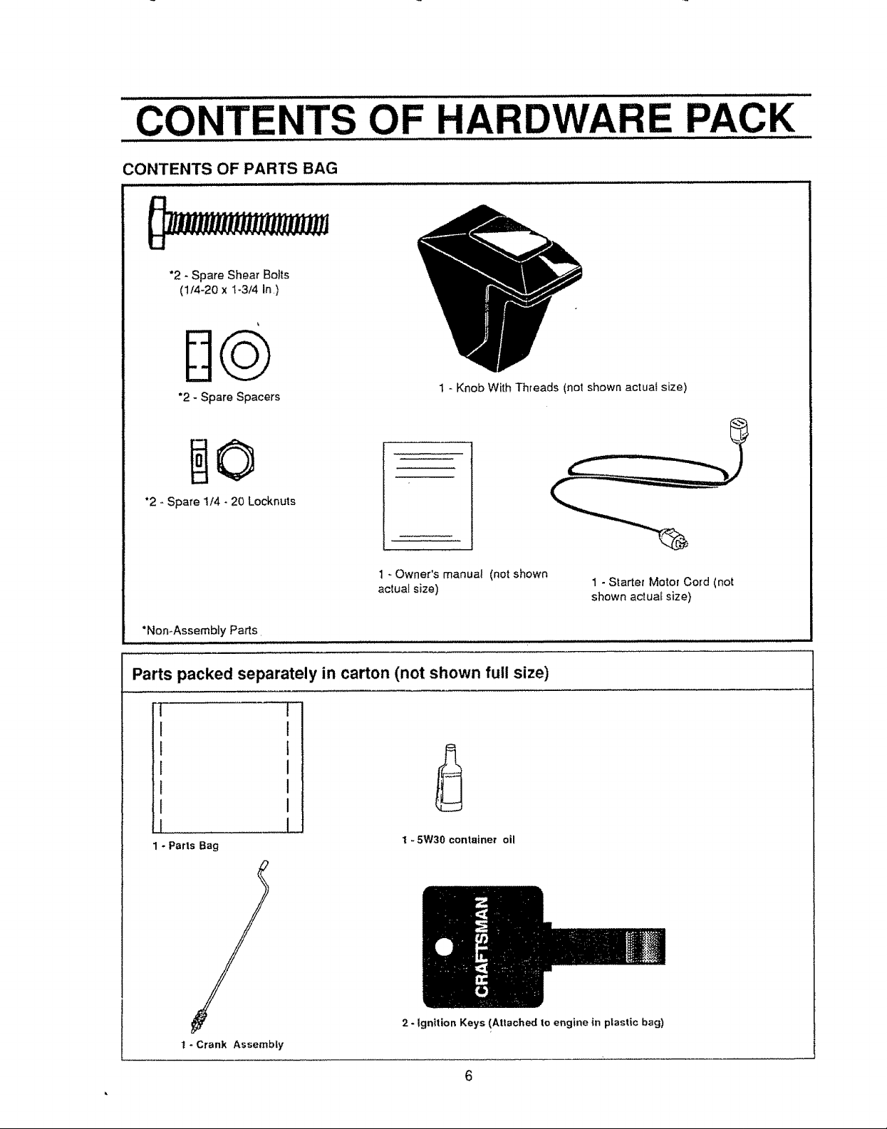
CONTENTS OF PARTS BAG
*2 - Spare Shear Bolts
(1/4-20 x I-3/4 In)
D@
"2 - Spare Spacers
*2 - Spare 1/4 - 20 Locknuts
1 - Knob With Threads (not shown actua! size)
RE PACK
1 _ Owner's manua! (not shown
actual size)
"Non-Assembly Parts,
Parts packed separately in carton (not shown full size)
q
I
l
r
I
I
1 - Parts Bag
I - 5W30 container oil
1 - Starter Motor Cord (not
shown ac_ua_size)
t - Crank Assembly
2 - Ignition Keys (Attached to engine in plastic bag)
6
ASS
LY
TOOLS REQUIRED FOR ASSEMBLY
1 - Knife (to cut carton and plastic ties)
2 - 1/2 inch wrenches (or adjustable wrenches)
2 - 9/16 inch wrenches (or adjustable wrenches)
2 - 3/4 inch wrenches (or adjustable wrenches)
1 - P_iers(to spread cotter pin)
1- Screwdriver
1 - Measuring Tape or Ruler
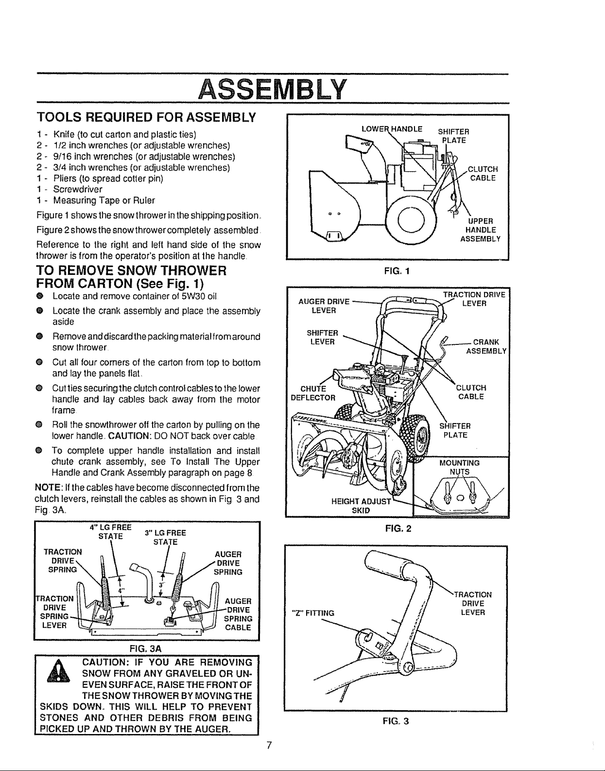
Figure 1 shows the snow throwerinthe shipping position.,
Figure 2showsthe snowthrower completely assembled.
Reference to the right and left hand side of the snow
thrower isfrom the operator's position at the handle,
TO REMOVE SNOW THROWER
FROM CARTON (See Fig. 1)
® Locate and remove container of 5W30 oil
®
Locate the crank assembly and place the assembly
aside
®
Remove anddiscardthe packing materialfrom around
snow thrower.
®
Cut all four corners of the carton from top to bottom
and lay the panels fiat,
®
Cutties securing the clutch control cables tothe lower
handle and lay cables back away from the motor
frame
® Roll the snowthrower off the carton by pulling on the
lower handle,,CAUTION: DO NOT back over cable
® To complete upper handle installationand install
chute crank assembly, see To Install The Upper
Handle and Crank Assembly paragraph on page 8
NOTE: Ifthe cables have become disconnected from the
clutch levers, reinstall the cables as shown in Fig 3 and
Fig, 3A,,
4" LG FREE
STATE 3" LG FREE
TRACTION _ / ,q AUGER
DRIVE,. "t_, / H -- DRIVE
STATE
i i iii,i i i
AUGER DRIVE
LEVER
SHIFTER
LEVER
CHUTE
DEFLECTOR
LOWEF
HEIGHT ADJUST
SKID
SHIFTER
PLATE
UPPER
HANDLE
ASSEMBLY
FIG. 1
TRACTION DRIVE
LEVER
FIG. 2
[ r%
DRIVEll _/_ ""- - $ '_L_.4"'DR_VE
SPRING_ _ If SPRING
LEVER °ABLE
FIG. 3A
,_ CAUTION: IF YOU ARE REMOVINGSNOW FROM ANY GRAVELED OR UN-
EVEN SURFACE, RAISETHE FRONTOF
THE SNOW THROWER BY MOVING THE
SKIDS DOWN° THIS WILL HELP TO PREVEN_
STONES AND OTHER DEBRIS FROM BEING
PICKED UP AND THROWN BY THE AUGER.
FION
DRIVE
"Z'FITTING
FIG. 3
7
LEVER
ASSEMBLV
HOW TO SET UP YOUR SNOW
THROWER
@ Your snow thrower is equipped with height adjust
skids (See Fig 2) on the outside of the auger
housing, To adjust the skid height for different
conditions, see To Adjust Skid Height paragraph on
page 18,
TO INSTALL THE UPPER HANDLE
AND CRANK ASSEMBLY
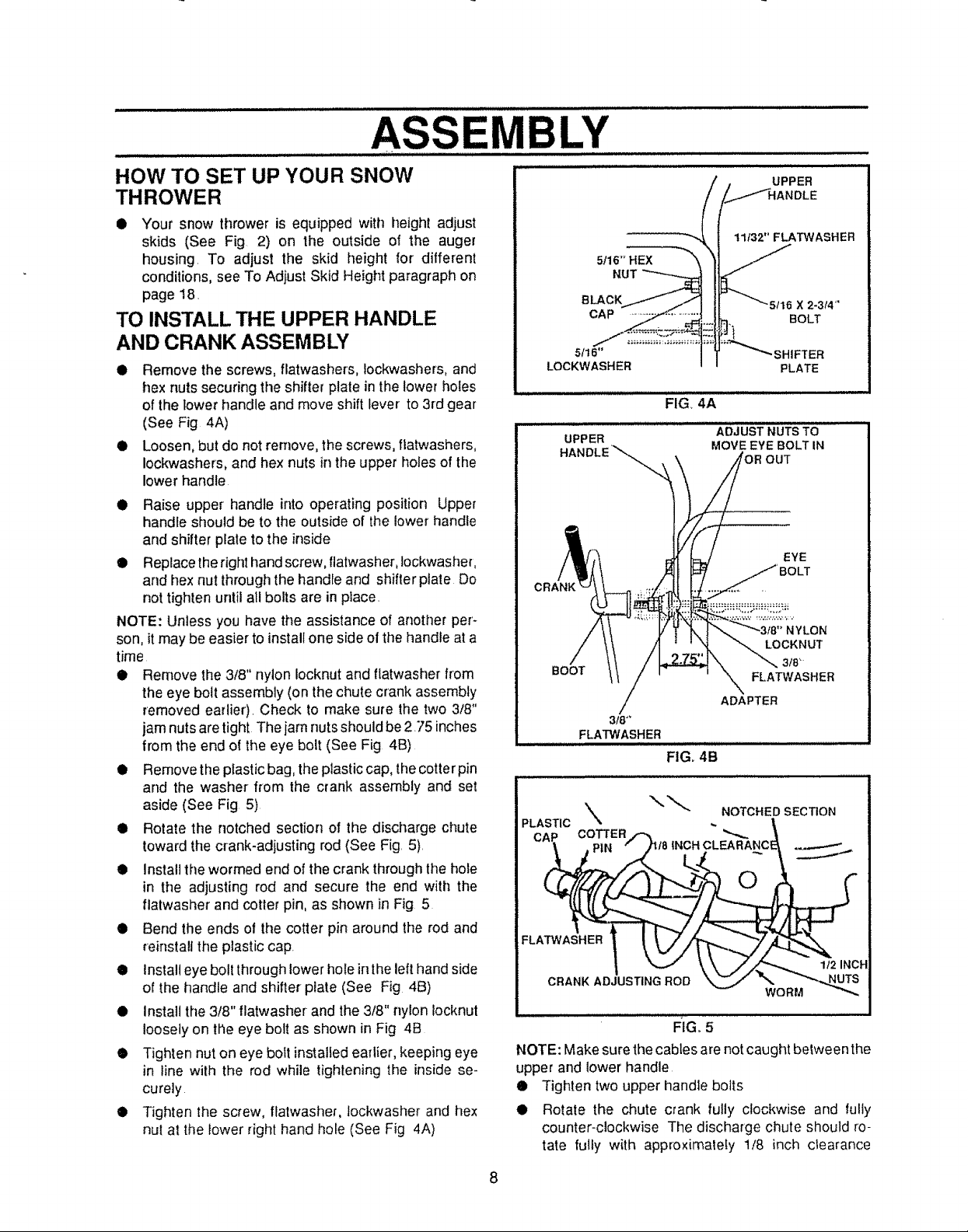
• Remove the screws, flatwashers, Iockwashers, and
hex nuts securing the shifter plate in the lower holes
of the towerhandle and move shift lever to 3rd gear
(See Fig 4A)
• Loosen, but do not remove, the screws, flatwashers,
Iockwashers, and hex nuts in the upper holes of the
lower handle
I Raise upper handle intooperating position Upper
handle should be to the outside of the lower handle
and shifter plate to the inside
I Replacetheright hand screw, flatwasher,iockwasher,
and hexnut throughthe handle and shifter plate Do
not tighten until all bolts are in place.
NOTE: Unless you have the assistance of another per'-
son, itmay be easier to install one side of the handle at a
time
i Remove the 3/8" nylon Iocknut and flatwasher from
the eye bolt assembly (onthe chute crank assembly
removed earlier). Check to make sure the two 3/8"
jamnuts are tight The jam nuts should be 2 75 inches
from the end o{ the eye bolt (See Fig 4B)
• Remove the plastic bag,the plastic cap, the cotter pin
and the washer from the crank assembly and set
aside (See Fig 5)
I Rotate the notched section of the discharge chute
toward the crank-adjusting rod (See Fig, 5),
@ Install the wormed end of the crank throughthe hole
in the adjusting rod and secure the end with the
flatwasher and cotter pin, as shown in Fig 5
@ Bend the ends of the cotter pin around the rod and
reinstall the plastic cap.
• install eye bolt throughlower hole in thelefthand side
of the handle and shifter plate (See Fig 4B)
I install the 3/8" tlatwasher and the 3/8" nylon Iocknut
loosely on the eye bolt as shown in Fig 4B
I Tighten nut on eye boft installedearlier, keeping eye
in line with the rod while tighteningthe insidese-
curely
i Tighten the screw, flatwasher, lockwasher and hex
nut at the towerright hand hole (See Fig 4A)
UPPER
11f32" FLATWASHER
X 2-3/4'"
5/16"
LOCKWASHER
UPPER
HANDLE'_,
BOOT
318""
FLATWASHER
FIG 4A
ADJUST NUTS TO
MOVE EYE BOLT IN
ADAPTER
FIGo 4B
PLATE
OUT
EYE
BOLT
NYLON
LOCKNUT
3/84
FLATWASHER
PLAST,C\ \ .NOTC.E{ SECTiON
CAP COTTERtt,,,,'_ t18
FLA L<.
NOTE: Make sure the cabtes are notcaught between the
upper and lower handle
• Tighten two upper handle bolts
• Rotate the chute crank fully clockwise and tully
- PiN INCH CLEARANCE_ _,,_
i _ \,".. .//S"'._ _/zINCH
RG_ 5
counter-clockwise The discharge chute should ro-
tate futly with approximately 1/8 inch clearance
8
ASSE LY
@ Rotate the chute crank fully clockwise and fully
counter-clockwise. The discharge chute should ro-
tate fully with approximately 1/8 inch clearance be-
tweenthe worm and the bottomof the notch (See Fig.
5)
® If the chute crank needs to be adjusted, go to lhe
Service andAdjustments sectionon page 18.Screws
securing chute clips at the base of the chute should
be slightly loose for easy rotation.
NOTE: Be sure the crank does not touch the side of the
engine or the cover will be scratched
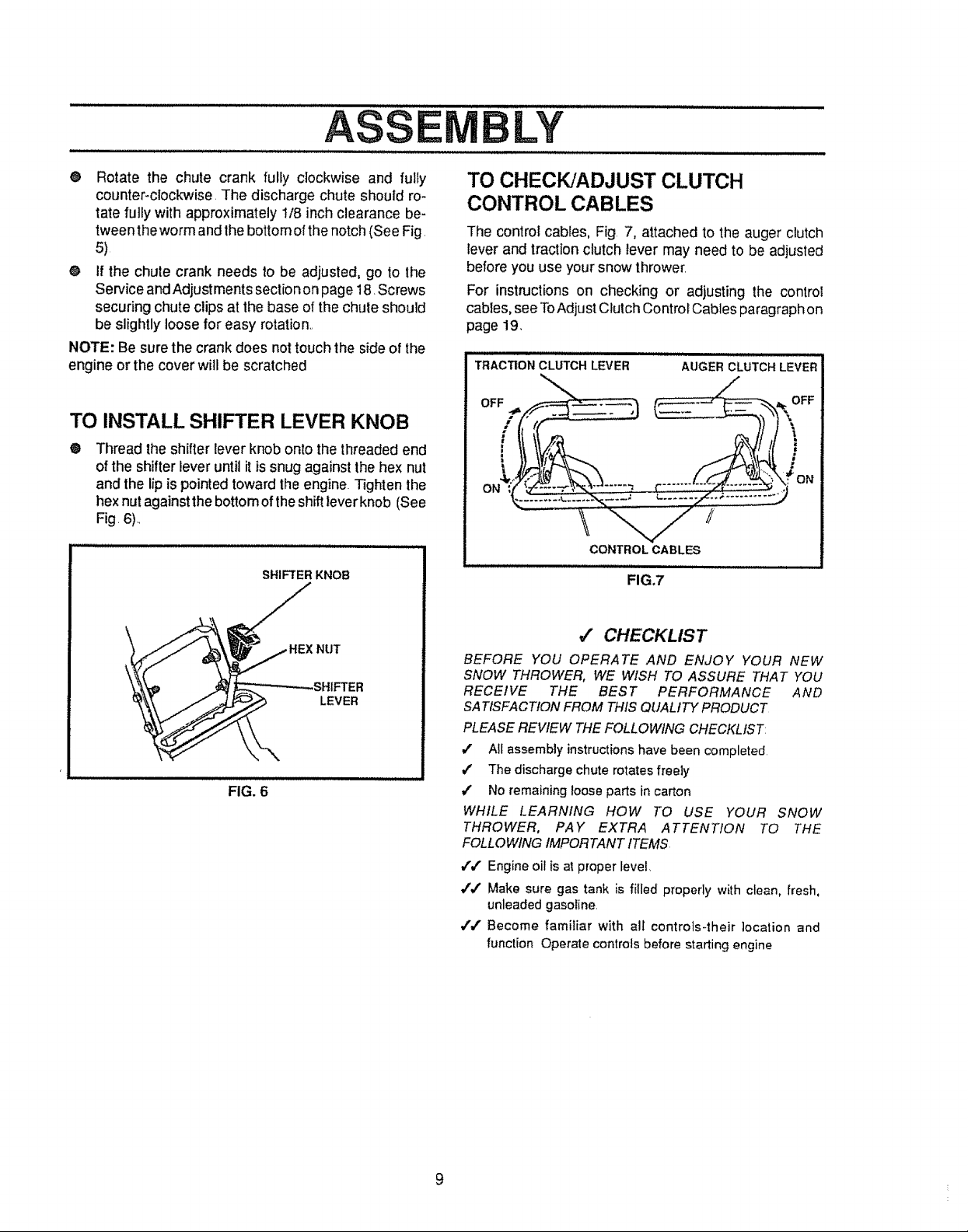
TO INSTALL SHIFTER LEVER KNOB
®
Thread the shifter lever knob ontothe threadedend
of the shifter lever until it issnug against the hex nut
and the lip is pointed toward Ihe engine. Tighten the
hex nutagainst the bottom ofthe shiftlever knob (See
Fig. 6)..
SHIFTER KNOB
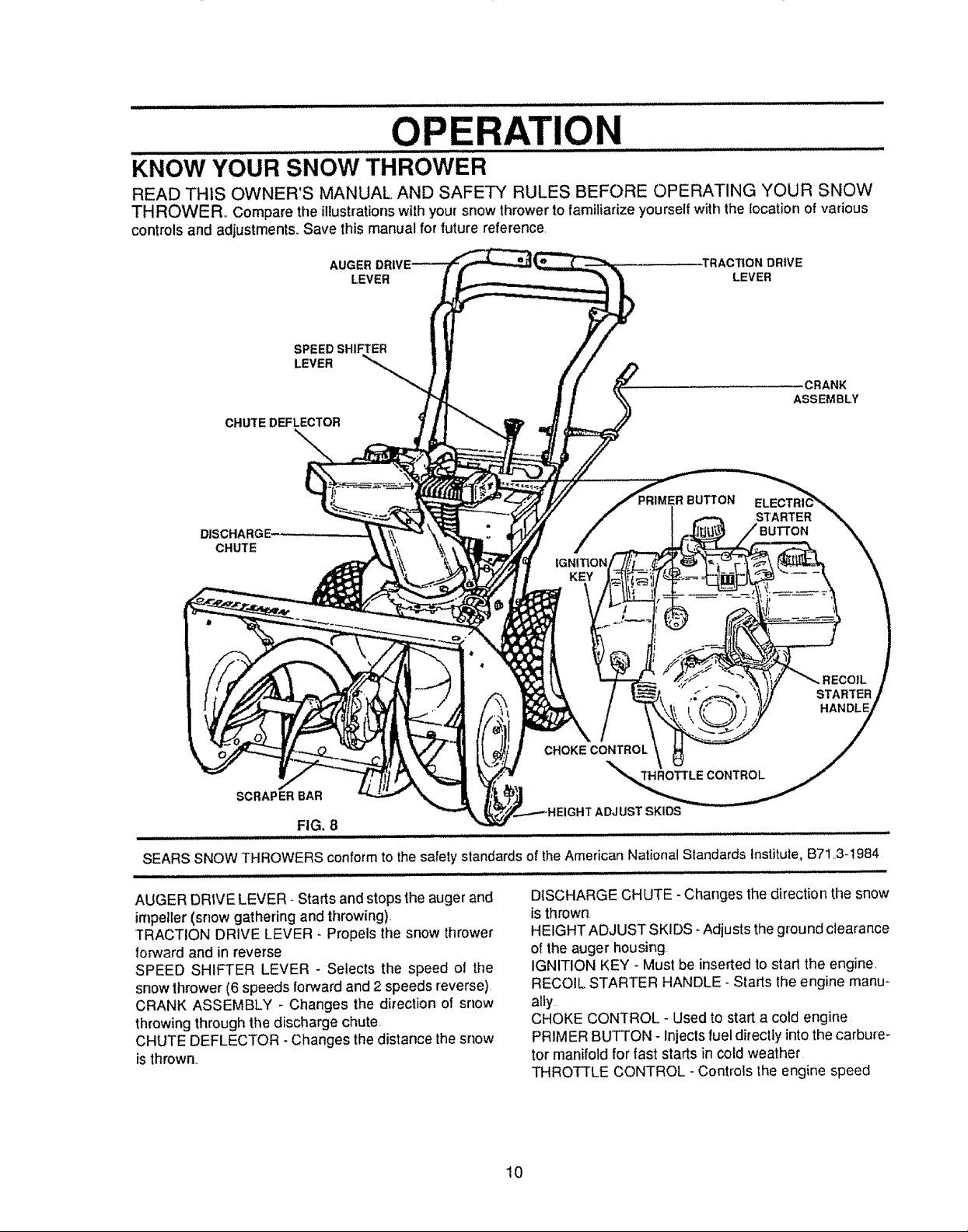
TO CHECK/ADJUST CLUTCH
CONTROL CABLES
The control cables, Fig. 7, attached to the auger clutch
lever and traction clutch lever may need to be adjusted
before you use your snow thrower.
For instructions on checking or adjusting the control
cabies, see ToAdjust Clutch Contro_Cables paragraph on
page 19.
TRACTION CLUTCH LEVER
CONTROLCABLES
FIG.7
AUGER CLUTCH LEVER
FIG. 6
LEVER
4' CHECKLIST
BEFORE YOU OPERATE AND ENJOY YOUR NEW
SNOW THROWER, WE WISH TO ASSURE THAT YOU
RECEIVE THE BEST PERFORMANCE AND
SATISFACTIONFROMTHISQUALt7-YPRODUCT
PLEASEREVIEW THEFOLLOWINGCHECKLIST:
,l A_Iassemblyinstructionshave beencompleted
/ The discharge chute rotates freely
/ No remaining loose parts in carton
WHILE LEARNING HOW TO USE YOUR SNOW
THROWER, PAY EXTRA ATTENTION TO THE
FOLLOWINGIMPORTANTITEMS
/,/' Engineoilisatproperlevel
/4' Make sure gas tank is filled properly with clean, fresh,
unleaded gasoline,
v'/ Become familiar with all controls-their ]ocation and
function Operate controls before starting engine
9
u,l/,
OPERATION
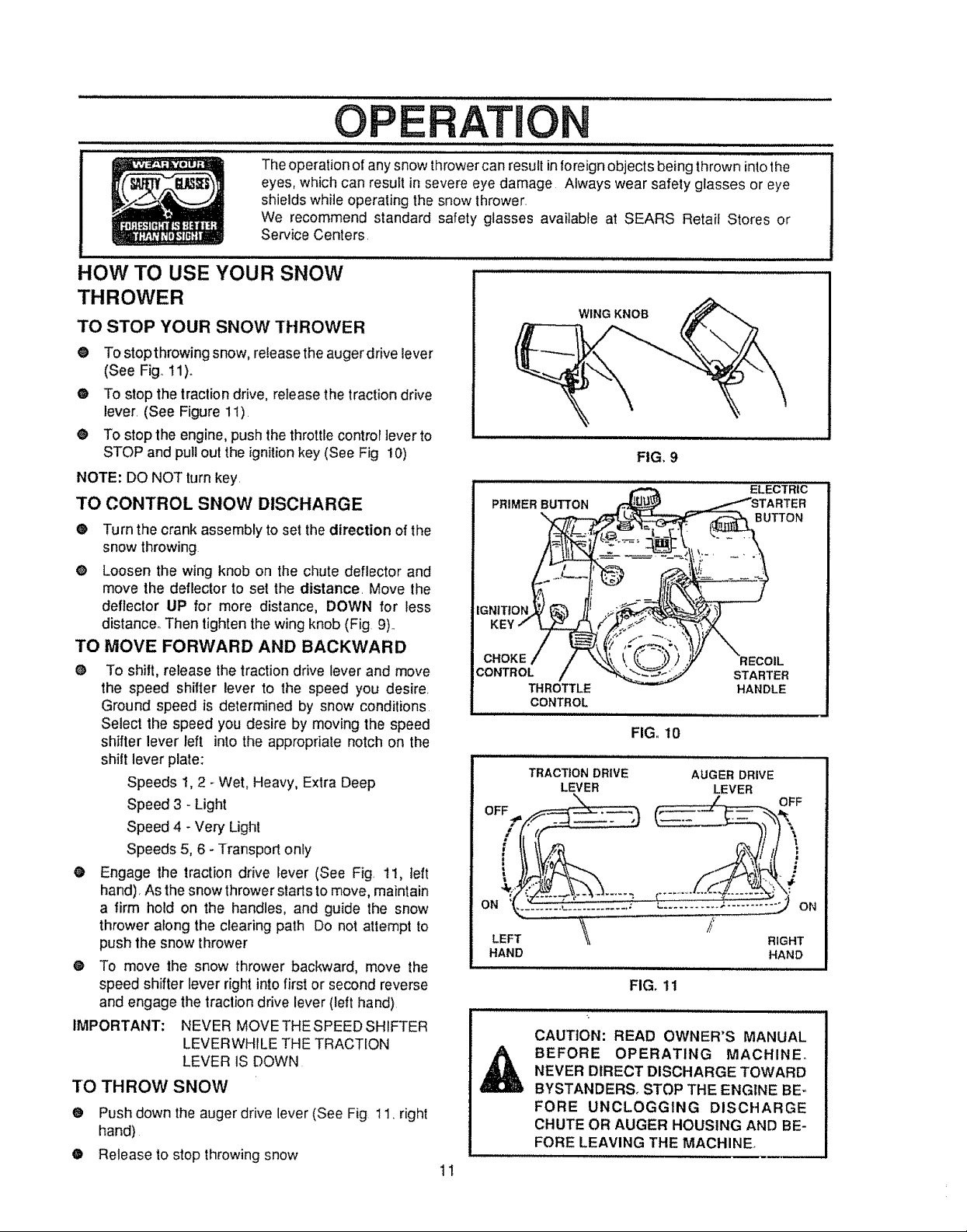
KNOW YOUR SNOW THROWER
READ THIS OWNER'S MANUAL AND SAFETY RULES BEFORE OPERATING YOUR SNOW
THROWER_ Compare the illustrations with your snow thrower to familiarize yourself with the location of various
controls and adjustments. Save this manual for future reference,
TRACTION DRIVE
LEVER LEVER
SPEED SHIFTER
LEVER
CRANK
ASSEMBLY
CHUTE DEFLECTOR
--..
IMER BUTTON
STARTER
DISCHARGE,
CHUTE
KEY
STARTER
HANDLE
CHOKE CONTROL
THROTTLE CONTROL
SCRAP ER BAR
ADJUST SKIDS
FIG. 8
SEARS SNOW THROWERS conform to the safety standards of theAmerican National Standards Institute, B71,,3-1984
AUGER DRtVE LEVER * Starts and stops the auger and
impeller (snow gathering and throwing),
TRACTION DRIVE LEVER- Propels the snow thrower
forward and in reverse
SPEED SHIFTER LEVER - Selects the speed ol the
snow thrower (6 speeds forward and 2 speeds reverse).
CRANK ASSEMBLY - Changes the direction of snow
throwing through the discharge chute
CHUTE DEFLECTOR -Changes the distance thesnow
isthrown,_
DISCHARGE CHUTE - Changes the direction the snow
isthrown
HEIGHT ADJUST SKIDS- Adjusts the ground clearance
of the auger housing.
IGNITION KEY - Must be inserted to start the engine,
RECOIL STARTER HANDLE- Starts the engine manu-
ally
CHOKE CONTROL - Used to start a cold engine
PRIMER BUTTON - injeclsfuel directiy into the carbure-
tor manifold for fast starts in cold weather
THROTt-LE CONTROL -Controls the engine speed
10
OPE TlO
Theoperation of any snow thrower can result inforeign objects being thrown into the
eyes, which can result in severe eye damage Always wear safety glasses or eye
shields while operating the snow thrower.
We recommend standard safety glasses available at SEARS Retail Stores or
Service Centers.
HOW TO USE YOUR SNOW
THROWER
TO STOP YOUR SNOW THROWER
@ To stopthrowing snow, release theaugerdrive lever
(See Fig°11).
@ To stop the traction drive, release the traction drive
lever. (See Figure 1!)
® To stop the engine, push the throttle control lever to
STOP and pull out the ignition key (See Fig 10)
NOTE: DO NOT turnkey.
TO CONTROL SNOW DISCHARGE
• Turn the crank assembly to set thedirection of the
snow throwing
O Loosen the wing knob on the chute deflector and
move the deflector to set the distance. Move the
deflector UP for more distance, DOWN for less
distance° Then tighten thewing knob (Fig 9).
TO MOVE FORWARD AND BACKWARD
0 To shilt, release the traction drive lever and move
the speed shifter lever to the speed you desire.
Ground speed is determined by snow conditions.
Select the speed you desire by moving the speed
shifter lever left into the appropriate notch on the
shift lever plate:
Speeds 1,2 _Wet, Heavy, Extra Deep
Speed 3 - Light
Speed 4 - Very Light
Speeds 5, 6 - Transport only
O Engage the traction drive lever (See Fig. 11, teft
hand), Asthe snow thrower starts to move, maintain
a firm hold on the handles, and guide the snow
thrower along the clearing path Do not attempt to
push the snow thrower
® To move the snow thrower backward, move the
speed shifter lever right into first or second reverse
and engage the traction drive lever (left hand)
IMPORTANT: NEVER MOVE THE SPEED SHIFTER
LEVERWHILE THE TRACTION
LEVER IS DOWN
TO THROW SNOW
O Push down theauger drive lever (See Fig 11, right
hand)
O Release to stop throwingsnow
11
PRIMERBUTTON
\
CONTROL
THROTTLE
CONTROL
TRACTION DRIVE
ON
LEFT '_
HAND
CAUTION: READ OWNER'S MANUAL
BEFORE OPERATING MACHINE.
NEVER DIRECT DISCHARGE TOWARD
BYSTANDERS_ STOP THE ENGINE BE-,
FORE UNCLOGGING DISCHARGE
CHUTE OR AUGER HOUSING AND BE-
FORE LEAVING THE MACHINE,
WING KNOB
/
LEVER
FIG, 9
ELECTRIC
BUTTON
STARTER
HANDLE
FIG, 10
AUGER DRIVE
LEVER
FIG. 11
OPERATION
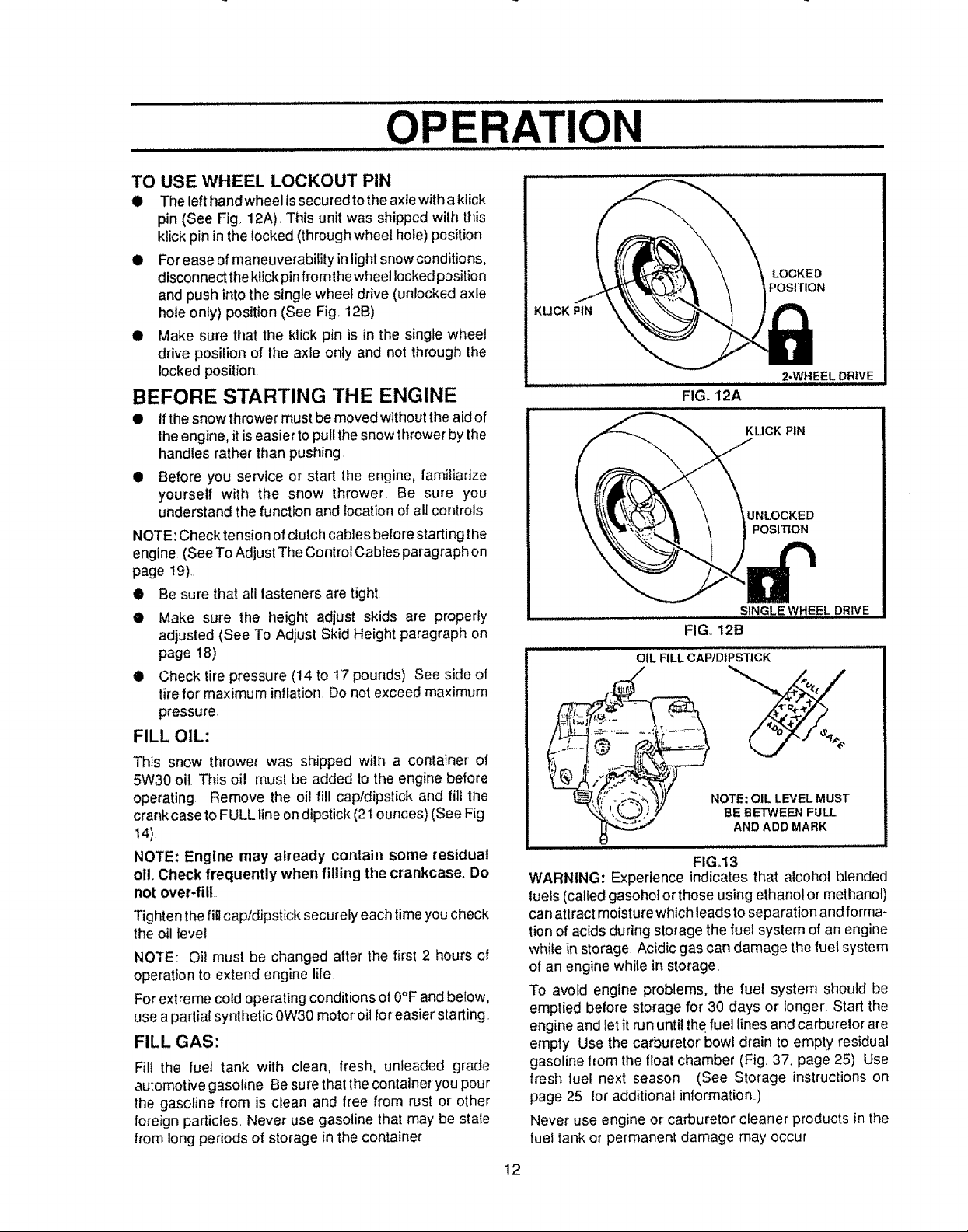
TO USE WHEEL LOCKOUT PIN
• The left hand wheel issecured tothe axlewith a klick
pin (See Fig., 12A), This unit was shipped with this
klick pin in the locked (through wheel hole) position
• Forease of maneuverability inlight snowconditions,
disconnect the klickpinfromthe wheel lockedposition
and push into the single wheel drive (unFockedaxle
hole only) position (See Fig, 12B)
• Make sure that the klick pin is in the single wheel
drive position of the axle only and not through the
lockedposition
BEFORE STARTING THE ENGINE
• Ifthe snow thrower must bemoved without the aid of
theengine, itis easier toputlthe snow thrower bythe
handles rather than pushing
II Before you service or start the engine, familiarize
yourself with the snow thrower, Be sure you
understand the function and location of all controls
NOTE: Check tension of clutch cables before starting the
engine (See To Adjust The Control Cables paragraph on
page 19),
• Be sure that all fasteners are tight
• Make sure the height adjust skids are properly
adjusted (See To Adjust Skid Height paragraph on
page 18),
• Check tire pressure (14 to 17 pounds) See side of
tirefor maximum inflation Do not exceed maximum
pressure
FILL OIL:
This snow thrower was shipped with a container of
5W30 oil This oil must be added to tile engine before
operating Remove the oil fill cap!dipstick and fill the
crankcase to FULL line ondipstick (21ounces) (SeeFig
14)
NOTE: Engine may already contain some residual
oil Check frequently when filling the crankcase, Do
not over.fill
Tightenthe fillcap/dipstick securely each time youcheck
the oil level
NOTE: Oil must be changed after the first 2 hours of
operation to extend engine life
For extreme cord operating conditions of 0°F and below,
use a partial synthetic 0W30 motor oil foreasier starting.
FILL GAS:
Fill the fuel tank with clean, fresh, unleaded grade
automotive gasoline Be surethat thecontainer you pour
the gasoline from is clean and free from rust or other
foreign particles, Never use gasoline that may be stale
from long periods of storage inthe container
LOCKED
POSITION
KLICK PIN
2-WHEEL DRIVE
FIG. 12A
KUCK PIN
UNLOCKED
POSITION
SINGLE WHEEL DRIVE
FIG+ 12B
OIL FILL CA'PID|PSTICK
NOTE: OIL LEVEL MUST
BE BETWEEN FULL
AND ADD MARK
FIG.13
WARNING: Experience indicates that alcohol blended
fuels (called gasohot or those using ethanol or methanol)
can attract moisture which leads toseparation and forma-
tion of acids during storage the fuel syslem of an engine
while in storage Acidic gas carl damage the fuel system
of an engine while in storage,
To avoid engine problems, the fuel system should be
emptied before storage for 30 days or longer, Start the
engine and letit run until the fuel lines and carburetor are
empty Use the carburetor bowl drain to empty residual
gasoline from the floatchamber (Fig, 37, page 25) Use
fresh fuel next season (See Storage instructions on
page 25 foradditional information,)
Never use engine or carburetor cleaner products in the
fuel tank or permanent damage may occur
12
O E
ATION
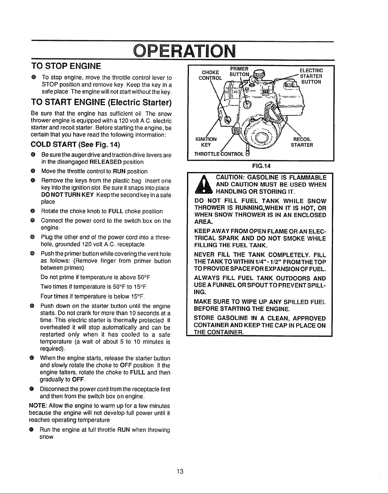
TO STOP ENGINE
O To stop engine, move the throttle control lever to
STOP position and remove key. Keep the key in a
safe place. The engine will notstart without the key.
TO START ENGINE (Electric Starter)
Be sure that the engine has sufficient oil The snow
thrower engine Jsequipped with a 120 voll AC. electric
starter and recoil starter_.Before starting the engine, be
certain that you have read the following intormatfon:
COLD START (See Fig. 14)
• Be sure the augerdrive and traction drive levers are
in the disengaged RELEASED position.
@ Move the throttle control to RUN position
O Remove the keys from the plastic bag. Insert one
key intothe ignition slot Be sure itsnaps into place
DO NOT TURN KEY Keep the second key in a safe
place
@ Rotate the choke knob to FULL choke position
O Connect the power cord to the switch box on the
engine.
O Plug the olher end of the power cord intoa three-
hole, grounded 120 volt A.C. receptacle.
O Push the primer button while covering the vent hole
as follows: (Remove finger from primer button
between primes).
Do not prime if temperature is above 50°F
Two times if temperature is 50°F to 15°F.
Four times if temperature is below 15°F.
@ Push down on the starter button until the engine
starts.. Do not crank for more than 10 seconds at a
time.,This electric starter is thermally protected I1
overheated it will stop aulomatically and can be
restarted only when it has cooled to a safe
temperature (a wait of about 5 to 10 minutes is
required).
O
When the engine starts, release the starter button
and slowly rotate the choke to OFF position. If the
engine falters, rotate the choke to FULL and then
gradually to OFF
• Disconnect the power cord fromthe receptacle first
and then from the switch box on engine,.
NOTE: Allow the engine to warm up for a few minutes
because the engine will not develop full power until il
reaches operating temperature
O Run the engine at fufithrottle RUN when throwing
snow,
CHOKE BUTTON
CONTROL
IGNITION RECOIL
KEY STARTER
THROTTLE CONTROL
_ AUTION: GASOLINE IS FLAMMABLE
DO NOT FILL FUEL TANK WHILE SNOW
THROWER IS RUNNING,WHEN IT IS HOT, OR
WHEN SNOW THROWER IS IN AN ENCLOSED
AREA,
KEEP AWAY FROM OPEN FLAME OR AN ELEC-
TRICAL SPARK AND DO NOT SMOKE WHILE
FILLING THE FUEL TANK,
NEVER FILL THE TANK COMPLETELY, FILL
THE TANKTOWlTHIN 1/4"-1f2" FROMTHETOP
TOPROVIDE SPACE FOR EXPANSION OF FUEL
ALWAYS FILL FUEL TANK OUTDOORS AND
USE AFUNNEL OR SPOUT TO PREVENTSPILL.
ING,
MAKE SURE TO WIPE UP ANY SPILLED FUEL
BEFORE STARTING THE ENGINE,
STORE GASOLINE IN A CLEAN, APPROVED
CONTAINER AND KEEP THE CAP IN PLACE ON
TH E CONTAINER.
PRIMER ELECTRIC
BUTTON
FIGo14
AND CAUTION MUST BE USED WHEN
HANDLING OR STORING IT,
13
iiiii,
OPERATION
CAUTION: NEVER RUN ENGINE
,_ INDOORS OR IN ENCLOSED,
CARBON MONOXIDE, AN ODORLESS AND
DEADLY GAS. KEEP HANDS, FEET, HAIR AND
LOOSE CLOTHING AWAY FROM ANY MOVING
PARTS ON ENGINE AND SNOW THROWER.
WARNING: TEMPERATURE OF MUFFLER AND
NEARBY AREAS MAY EXCEED 150° F. AVOID
THESE AREAS°
DO NOT ALLOW CHILDREN OR YOUNG TEEN-
AGERS TO OPERATE OR BE NEAR SNOW
THROWER WHILE IT IS OPERATING.
• RELEASE AUGER DRIVE AND TRACTION
DRIVE LEVERS.
• MOVE THROI3FLE LEVER TO STOP POSI-
TION,
• REMOVE (DO NOT TURN) IGNITION KEY,
• DISCONNECT SPARK PLUG WIRE.
• DO NOT PLACE YOUR HANDS IN THE
AUGER OR DISCHARGE CHUTE. USE A
PRY BAR°
TO START ENGINE (Recoil Starter)
Be sure that the engine has sufficient oil. Belore starting
the engine, be certain that you have read the following
information:
COLD START (See Fig. 14)
• Be sure the auger drive and the tractiondrive levers
are inthe disengaged RELEASED position
Move the throttlecontrolto RUN positionO
O
Pull thestarter handle rapidly Do not allow the handle
to snap back, but allow it to rewind slowly while
keeping a firm hold on the starter handle.
• Asthe engine warms up and begins to operate eve nly,
rotate the choke knob slowly to OFF position If the
engine falters, return to FULL choke, then slowly
move to OFF choke position
NOTE: Allow the engine to warm up for a few minutes
because the engine will not develop full power until it
reaches operating temperature
• Runthe engine ator neat thetop speed whenthrowing
snow
POORLY VENTILATED AREAS.
ENGINE EXHAUST CONTAINS
CAUTION: DO NOT ATTEMPT TO RE-
MOVE ANY ITEM THAT MAY BECOME
LODGED IN AUGER WITHOUT TAKING
THE FOLLOWING PRECAUTIONS:
WARM START
Ifrestarting awarmenginealter a short shutdown, rotate
choke to OFF instead of FULL and do not push the
primer button.
FROZEN STARTER
If the starter isfrozen and will not turn engine:
@ Pull as much rope out of the starter as possible.
@ Release the starter handle and let it snap back
against the starter.
If the engine still fails to start, push the primer buttontwo
or three timesagain and repeat the two previous sleps
until the engine starts Then continue with the directions
for cold start
To help prevent possible freeze-up of recoil starter and
engine controls, proceed as follows after each snow
removal job
• With the engine running, pull the starter rope hard
with acontinuous full arm stroke three or four times
Pulling of starter rope will produce a loud clattering
sound. This is not harmful to the engine or starter.
• With the engine not running, wipe all snow and
moisture from the carburetor cover in area of control
levers Also move throttle control choke control, and
starter handle several times.
SNOW THROWING TIPS
® For maximum snow thrower efficiency in removing
snow, adjust ground speed, NEVER the throttle=Go
slower in deep, freezing, or wet snow. If the track
slips,reduce forward speed The engine isdesigned
to deliver maximum pedormance at full throttle and
should be run at this power setting at aUtimes.
• Most elficient snow throwing is accomplished when
the snow is removed irnmediately after it falls..
• For complete snow removal, slightly overlap each
path previously taken
• Thesnow shouldbedischarged downwind whenever
possible.
• For normal usage, setthe skids so that the scraper
baris 1/8"above theskids. Forexlremely hardpacked
snow surfaces, adjust the skids upward so that the
scraper bar louches the ground
• On gravel or'crushed rock surfaces, set the skids at
1-1/4" below the scraper bar (see To Adjust Skid
Height paragraph on page 18) Stones and gravel
musl not be picked up and thrown by the machine.
• After the snow throw!ng job has been completed,
allow the engine toidle for a few minutes, which will
melt snow and accumulated ice off the engine.
® Clean the snow thrower thoroughly after' each use.
• Remove ice and snow accumulation and all debris
from the entire snow thrower, and flush with water (if
possible) to remove all salt or other chemicals Wipe
snow thrower dry
14
GUSTO E
ES PaN S B/IIII'IIIIIII/Ij1/11¸¸¸¸1111ii LmTm ES
iiiiiiiiiiiiii i iiiiiii
SERVICE RECORDS
Fill in dates as you complete
regular service
After Before As Every Every Every Each Before
SCHEDULE
iiiii IIHIL II II
First 2 Each Needed 5 t0 25 Season Storage
hours Use Hours Hours Hours
Check Engine Oi! Level ,_ _
Change Engine Oil ,I_ _
Tighten All Screws and Nuts _ V _'
Lubricate All Pivot Points
Lubricate Auger Shaft (See Shear
iBolt Replacement)
Lubricate Disc Drive PlateZerk (See
ICustomer Responsibilities}
Check Auger Clutch Cable
Adjustment (See Cable Adjustment)
Check Traction Clutch Cable
Adjustment (See CableAdjustment)
Adjust Drive Belts V 'I
Check Fuel
Drain Fuel V,#
It'
!.," v"
........ i.
SERVICE
DATES
, , = l_
Replace Spark Plug _
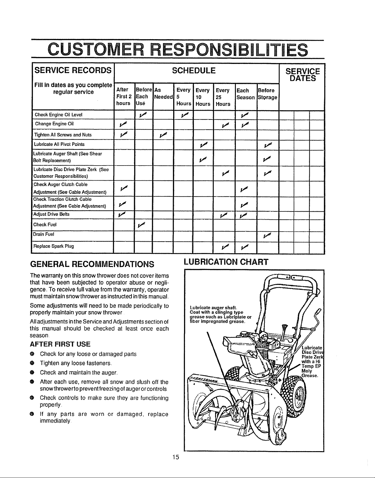
GENERAL RECOMMENDATIONS
LUBRICATION CHART
The warrantyonthis snow thrower does not cover items
that have been subjected to operator abuse or negli-
gence, To receive full value from the warranty, operator
must maintain snow thrower as instructed inthis manual,
Some adjustments will need to be made periodically to
properly maintain your snow thrower
All adjustments inthe Service and Adjustments section of
Lubricate auger shafL
Coat with a clinging type
grease such as Lubr|plate or
fiber impregnated grease.,
this manual should be checked at least once each
season
AFTER FIRST USE
o Check for any loose or damaged pads
® Tighten any loose fasteners
• Check and maintain the auger_
• After each use, remove all snow and slush off the
snowthrowerto prevent freezing of auger orcontrols
® Check controls to make sure they are functioning
properly,
• tf any parts are worn or damaged, replace
immediately
t5
CUSTOMER RESPONSIBILITIES
,JJl,i
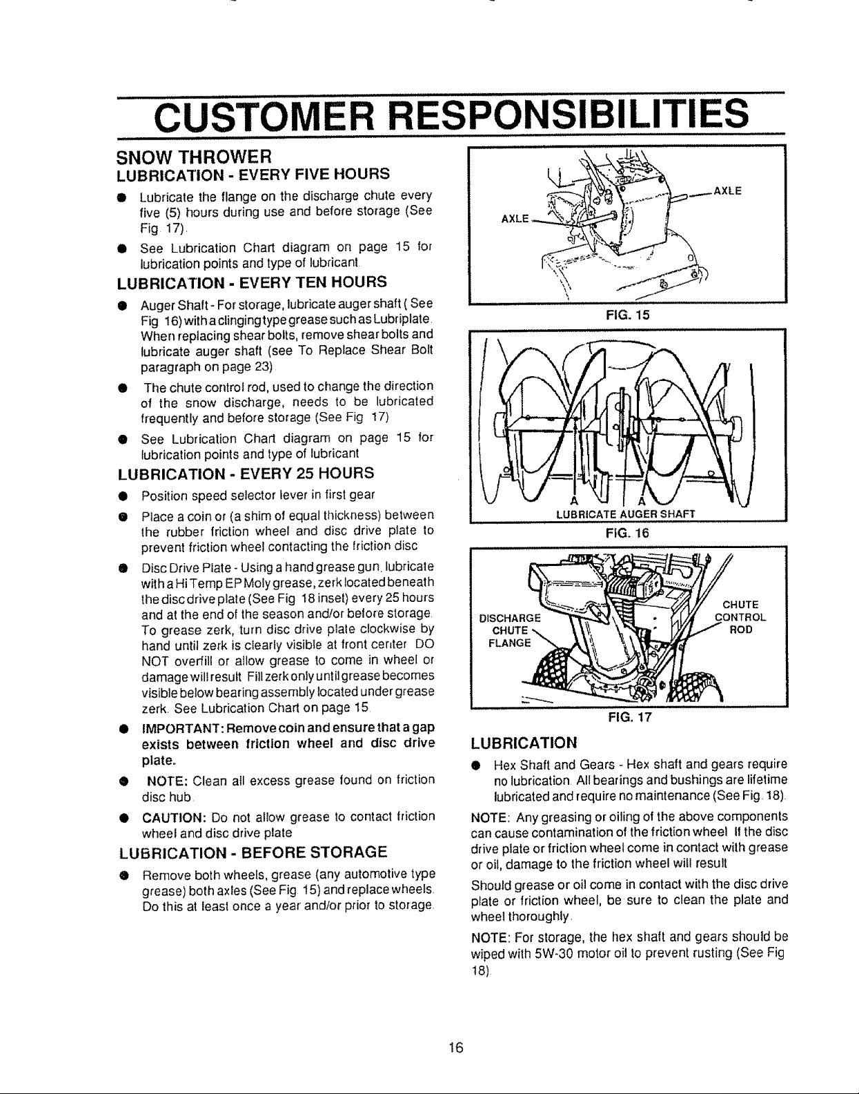
SNOW THROWER
LUBRICATION - EVERY FIVE HOURS
® Lubricate the flange on the discharge chute every
five (5) hours during use and before storage (See
Fig 17),
• See Lubrication Chart diagram on page 15 for
lubrication points and type of lubricant
LUBRICATION - EVERY TEN HOURS
• Auger Shaft- For storage, lubricate auger shaft ( See
When replacingshear bolts, remove shear bolts and
• The chute control rod, used to change the direction
of the snow discharge, needs to be lubricated
• See Lubrication Chart diagram on page 15 for
LUBRICATION - EVERY 25 HOURS
• Position speed selector lever in first gear
• Place a coin or (a shim of equal thickness) between
• Disc Drive Plate- Using a hand grease gun lubricate
II IMPORTANT: Remove coin and ensure that a gap
® NOTE: Clean all excess grease lound on friction
t) CAUTION: Do not allow grease to contact friction
LUBRICATION - BEFORE STORAGE
® Remove both wheels, grease (any automotive type
lull
Fig 16)with aclinging type grease suchas Lubriplate,
lubricate auger shaft (see To Replace Shear Bolt
paragraph on page 23)
frequently and before storage (See Fig 17)
lubricationpoints and type of lubricant
the rubber friction wheel and disc drive plate to
prevent friction wheel contacting the friction disc
wit h a Hi Temp EP Moly grease, zerk iocated beneath
the disc drive plate (See Fig 18 inset) every 25 hours
and at the end of the season and/or before storage.
To grease zerk, turn disc drive plate clockwise by
hand until zerk is clearly visible at front cer_ter DO
NOT overfill or allow grease to come in wheel or
damagewill result Fill zerkontyuntiigrease becomes
visible below bearing assembly located under grease
zerk See Lubrication Chart on page 15
exists between friction wheel and disc drive
plate.
disc hub.
wheel and disc drive plate
grease) both axles (See Fig 15) and replacewheets.
Do this at least once a year and/or prior to storage,
i II i II i,illl i lll i _LL-
_ AXLE
AXLE _
FIG. 15
LUBRICATEAUGER'SHAFT
FIG. 16
DISCHARGE
CHUTE
FLANGE
FIG. 17
LUBRICATION
• Hex Shaft and Gears - Hex shaft and gears requ[re
no lubrication All bearings and bushings are lifetime
lubricated and requireno maintenance (See Fig, 18),
NOTE: Any greasing or oiling of the above components
can cause contamination of the friction wheel Ifthe disc
drive plate or friction wheel come in contact with grease
or oil, damage tothe friction wheel will result
Should grease or oil come in contact with the disc drive
plate or friction wheel, be sure to clean the plate and
wheel thoroughly.
NOTE: For storage, the hex shalt and gears should be
wiped with 5W-30 motor oil to prevent rusting (See Fig
18)
CHUTE
CONTROL
ROD
16
CUSTO E
PONSI LITI
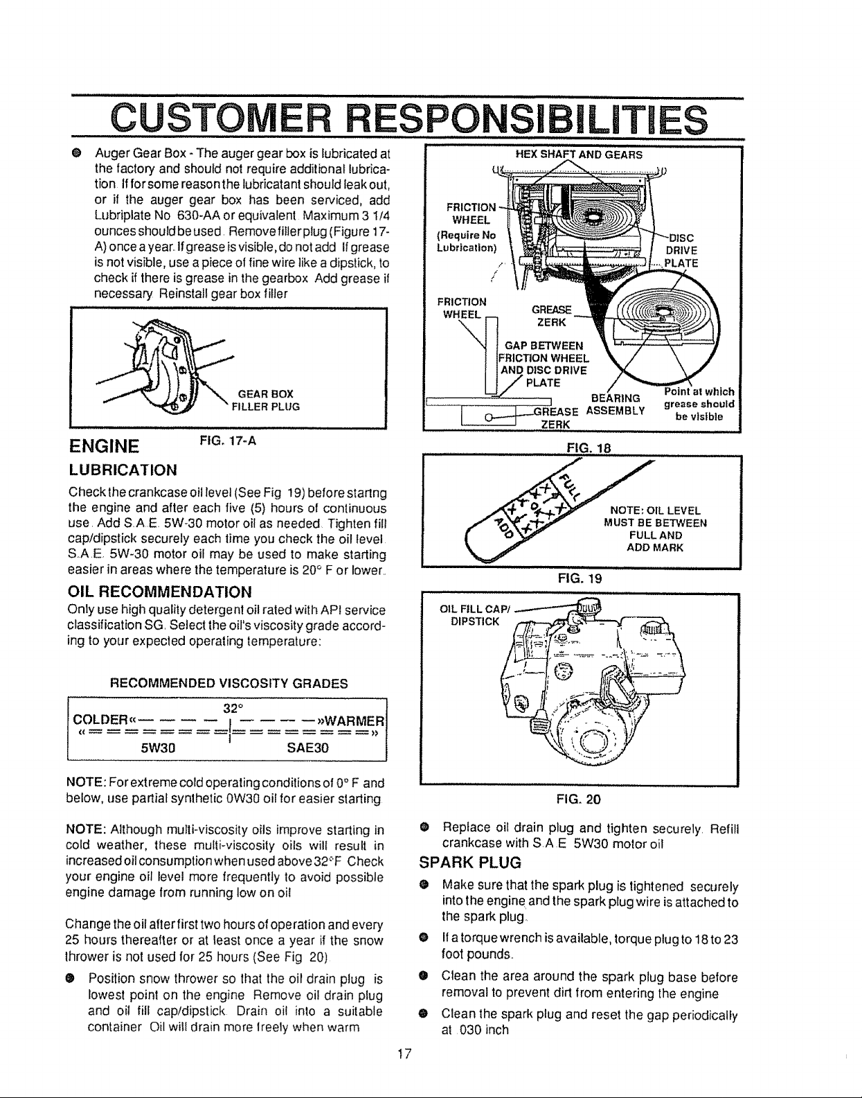
® Auger Gear Box - The auger gear box is lubricated at
the factory and should not require additional lubrica-
tion ifforsome reasonthe lubricatant should leakout,
or if the auger gear box has been serviced, add
Lubfiplate No 630-AA or equivalent Maximum 3 1/4
ounces shouldbeused, Removefillerplug (Figure 17-
A)once ayear,,Ifgrease is visible,do notadd Ifgrease
is notvisible, use a piece of fine wire like a dipstick, to
check if there is grease inthe gearbox Add grease if
necessary Reinstall gear box filler
GEAR BOX
° _ " FILLER PLUG
ENGINE FIG. 17-A
LUBRICATION
Check thecrankcase oil level (See Fig 19)before staring
the engine and after each five (5) hours o! continuous
USerAdd SAE. 5W-30 motor oil as needed Tighten lilt
cap/dipstick securely each time you check the oil level
S_A,E, 5W-30 motor oil may be used to make starting
easier in areas where the temperature is 20° For lower,,
OIL RECOMMENDATION
Only use high quality detergent oilrated with API service
classification SG Select theoil's viscosity grade accord-
ing to your expecled operating temperature:
HEX SHAFT AND GEARS
WHEEL
(Require No
Lubrication)
FRICTION
WHEEL
I -_'......... BEARING
i _GREASE ASSEMBLY
........ ZERK
GREASE
ZERK
GAP BETWEEN
=RICTtON WHEEL
AND DISC DRIVE
PLATE
........FIG. 18
_IL LEVEL
.,/ "1_'_'3_' "_eF" MUST BE BETWEEN
_" -0_ f" FULL AND
FIG. 19
OIL FILL CAP/
DIPSTICK
DRIVE
PLATE
Point at which
grease should
be visible
ADD MARK
RECOMMENDED VISCOSITY GRADES
32°
COLDER (€ I )_WARMER
5W30 SAE30
1
NOTE: For extreme cold operating conditions of0° F and
below, use partial synthetic 0W30 oil for easier starting
NOTE: Although multi-viscosity oils improve starting in
cold weather, these mufti-viscosity oils will result in
increased oil consumption when used above32_'FCheck
your engine oil level more frequently to avoid possible
engine damage from running low on oil
Change theoil afterfirst two hours ofoperation and every
25 hours thereafter or at least once a year if the snow
thrower is not used for 25 hours (See Fig 20)
• Position snow thrower so that the oil drain ptug is
_owestpoint on the engine Remove oHdrain plug
and oil fill cap/dipstick Drain oil into a suitable
container Oil will drain more lreely when warm
FIG. 20
O Replace oil drain plug and tighten securely, Refill
crankcase with S,A E 5W30 motor oil
SPARK PLUG
o
Make sure thatthe spark plug is tightened securely
into the engine,and the spark plug wire is attached to
the spark plug
o
Ifatorquewrench isavailable, torque plug to 18to 23
foot pounds..
O
Clean the area around the spark plug base before
removal to prevent dirt from entering the engine
0
Clean the spark plug and reset the gap periodically
at 030 inch
I7
SERVICE AND ADJUSTMENTS
CAUTION: ALWAYS DtSCONNECTTHE
SPARK PLUG WIRE AND TIE BACK
AWAY FROM THE PLUG BEFORE MAK-
ING ANY ADJUSTMENTS OR REPAIRS.
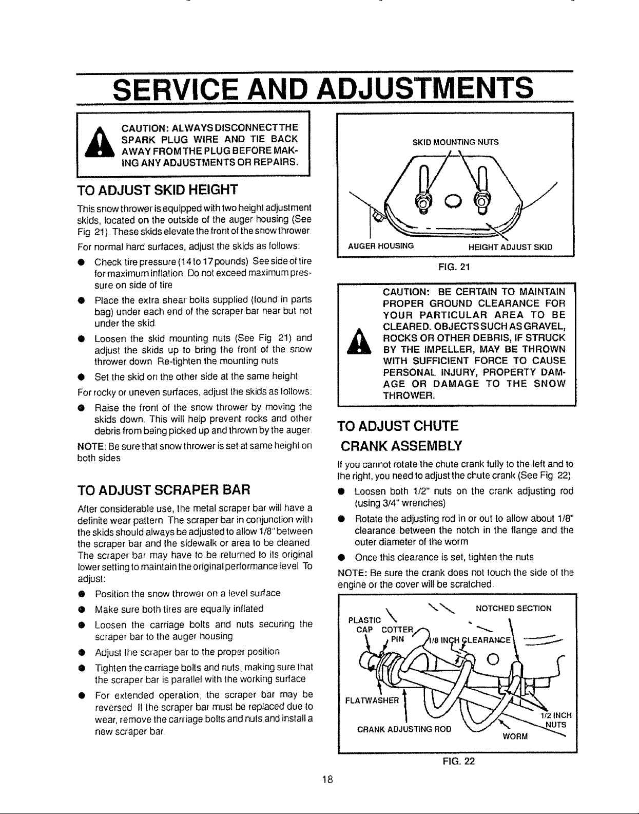
TO ADJUST SKID HEIGHT
This snow thrower isequipped with two height adjustment
skids, located on the outside of the auger housing (See
Fig 2!)These skids elevate the front of the snow thrower
For normal hard surfaces, adjust the skids as follows:
• Check tire pressure (14 to 17 pounds) See sicle of tire
for maximum inflation Do not exceed maximum pres-
sure on side of tire
• Place the extra shear bolts supplied (found in parts
bag) under each end of the scraper bar near but not
under' the skid
• Loosen the skid mounting nuts (See Fig 21) and
adjust the skids up to bring the front of the snow
thrower down Re-tighten the mounting nuts
Q Set the skid on the other side at the same height
For rocky or uneven surfaces, adjust the skids as follows:
• Raise the front of the snow thrower by moving the
skids down.. This will help prevent rocks and other
debris from being picked up and thrown by the auger
NOTE: Be sure that snow thrower is set at same height on
both sides
TO ADJUST SCRAPER BAR
After considerable use, the metal scraper bar will have a
definite wear pattern The scraper bar inconjunction with
the skidsshould always beadjusted toallow 1/8' between
the scraper bar and the sidewalk or area to be cleaned
The scraper bar may have to be returned to its original
lower settingto maintain the original performance level To
adjust:
• Position the snow throweron a level surface
• Make sure both tires are equally inflated
• Loosen the carriage bolts and nuts securing the
scraper bar to the augerhousing
i Adjust thescraper bar to the proper position
@ Tighten the carriage bolts and nuts, making sure that
the scraper bar is parallel with the working surface
• For extended operation, the scraper bar may be
reversed If the scraper bar must be replaceddue fo
wear, remove thecarriage bolts and nuts and install a
new scraper bar
SKID MOUNTING Nu_rs
AUGER HOUSING HEIGHT ADJ UST SKID
iii =l u=uu,
FIG. 21
CAUTION: BE CERTAIN TO MAINTAIN
PROPER GROUND CLEARANCE FOR
YOUR PARTICULAR AREA TO BE
CLEARED. OBJECTS S UCH AS GRAVEL,
ROCKS OR OTHER DEBRIS, IF STRUCK
BY THE IMPELLER, MAY BE THROWN
WiTH SUFFICIENT FORCE TO CAUSE
PERSONAL INJURY, PROPERTY DAM-
AGE OR DAMAGE TO THE SNOW
THROWER.
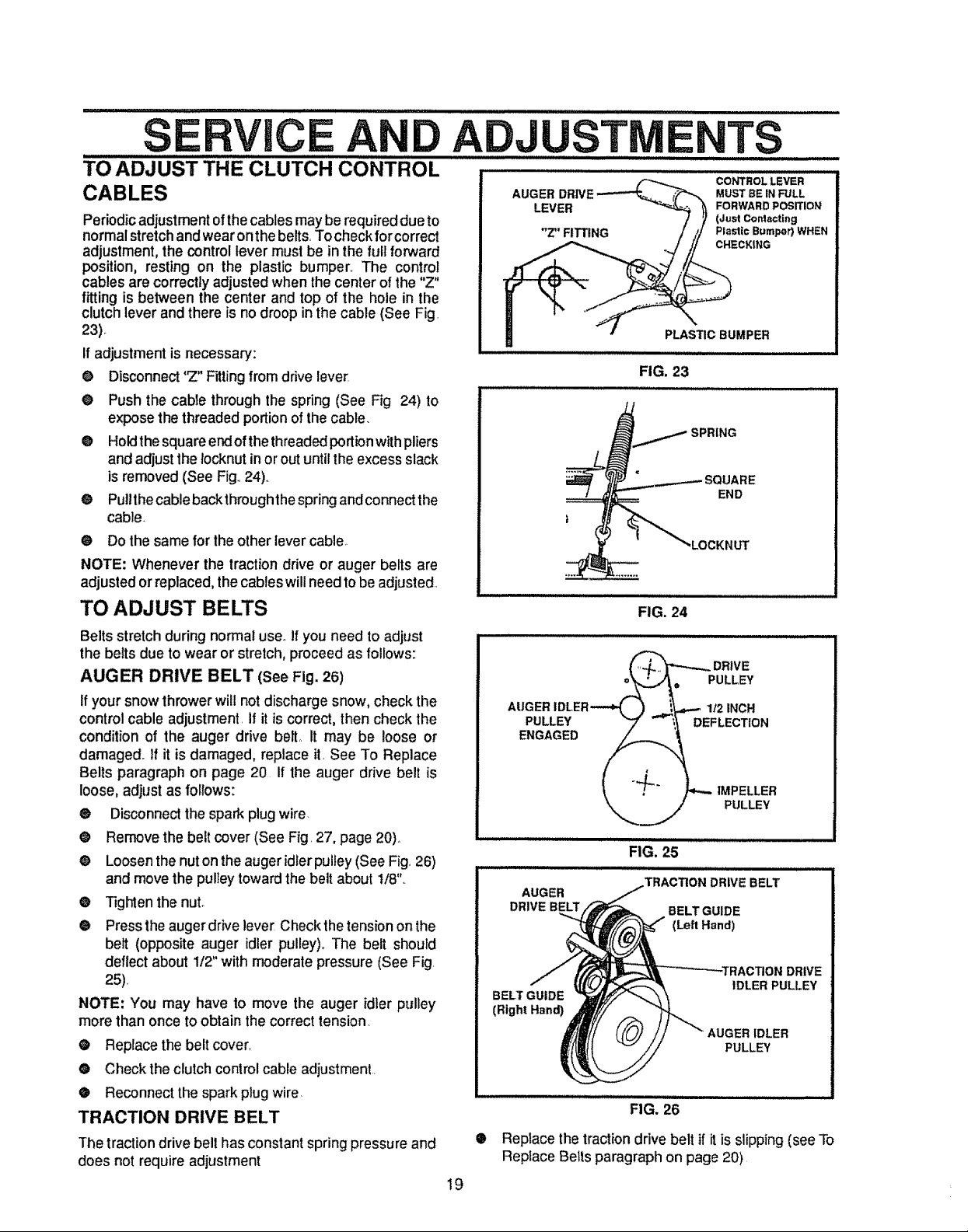
TO ADJUST CHUTE
CRANK ASSEMBLY
Ifyou cannot rotate the chute crank fully to the left and to
the right, you need to adjust the chute crank (See Fig 22)
• Loosen both 1/2" nuts on the crank adjusting rod
(using 314" wrenches)
• Rotate the adjusting rod in or out to allow about 1/8"
clearance between the notch in the flange and the
outer diameter of the worm
• Once this clearance is set, tighten the nuts
NOTE: Be sure the crank does not touch the side of the
engine or the cover will be scratched.
PLASTIC _ NOTCHEDSECTION
CAP COTTERJ'_ " "_,_ \
FL PIN 18IN_.. LEARANCE "_.
1 _J" \'k.J'_.._I'2',NCH
18
FIG. 22
TO ADJUST THE CLUTCH C6'N'TROL
CABLES
Periodic adjustment of the cables may be required due to
normal stretch and wear onthe belts, To check for correct
adjustment, the control lever must be in the full forward
position, resting on the plastic bumper,, The control
cables are correctly adjusted when the center of the "Z"
fitting is between the center and top of the hole in the
clutch lever and there is no droop in the cable (See Fig.
23)°
If adjustment is necessary:
O Disconnect '_" Fitting from drive lever
O
Push the cable through the spring (See Fig 24) to
expose the threaded portion of the cable.
®
Holdthe squareend ofthe threadedportionwith pliers
and adjust the Iocknut in or out untilthe excess slack
isremoved (See Fig,,24),,
®
Pullthecableback throughthespring andconnect the
cable.
O Do thesame for the other lever cable,
NOTE: Whenever the tractiondrive or auger belts are
adjustedorreplaced, thecableswillneed tobe adjusted.
TO ADJUST BELTS
Belts stretch duringnormaluser Ifyou need toadjust
the belts due to wear or stretch, proceed as follows:
AUGER DRIVE BELT (See Fig. 26)
If your snow thrower will not discharge snow, check the
control cable adjustment, If it is correct, then check the
condition of the auger drive bell it may be loose or
damaged° If it is damaged, replace it, See To Replace
Belts paragraph on page 20 If the auger drive belt is
loose, adjust as follows:
@ Disconnect the spark plug wire
@ Remove the belt cover (See Fig, 27, page 20)°
® Loosen the nuton the auger idlerpulley (See Fig, 26)
and move the pulley toward the belt about t/8'L
@ Tighten the nut.
@ Presstheauger drive lever Check the tension on the
belt (opposite auger idler pulley). The belt should
deflect about 1/2" with moderate pressure (See Fig.
25),
NOTE: You may have to move the auger idler pulley
more than once to obtain the correct tension.
@ Replace the belt cover,
@ Check theclutch control cable adjustment.
@ Reconnect the spark plug wire
TRACTION DRIVE BELT
The traction drive belt has constant spring pressure and
does not require adjustment
!9
AUGER MUST BE IN FULL
LEVER FORWARD POSITION
"Z" FITTING Plastic Bumpor) WHEN
PLASTICBUMPER
FIG. 23
CONTROL LEVER
(Just Contacting
CHECKING
SPRING
SQUARE
END
"LOCKNUT
FIG. 24
_ DRIVE
_,_. PULLEY
AUGER IDLER_ ) _._.,_',_._I/2INCH
., /.,--. IMPELLER
_,,,.J PLILLEY
illlllllll ii,,llll,i i ii i j i i
FIG. 25
AUGER
DRIVEBELT BELTGUIDE
BELTGUIDE
(Right Hand)
®
Replace thetractiondrive belt if it isslipping (see To
Replace Belts paragraphon page 20)
.TRACTIONDRIVEBELT
(Left Hand)
IDLER PULLEY
_ER IDLER
PULLEY
FIG. 26
DRIVE
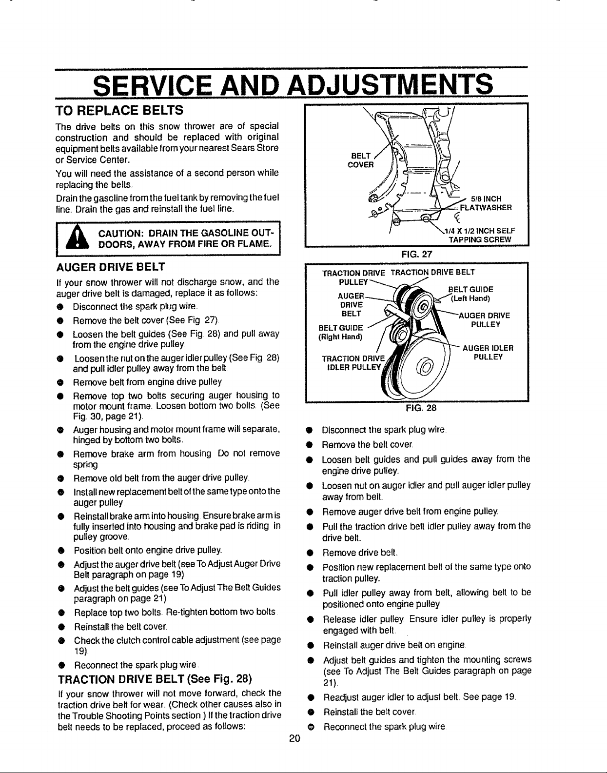
TO REPLACE BELTS
The drive belts on this snow thrower are of special
construction and should be replaced with original
equipment beltsavailable from your'nearest Sears Store
or Service Center.
You will need the assistance of a second person while
replacing the belts,
Drainthe gasoline from the fueltank by removing the fuel
line..Drain the gas and reinstall the fuel line.
CAUTION: DRAIN THE GASOLINE OUT- 1
DOORS, AWAY FROM FIRE OR FLAME.
AUGER DRIVE BELT
If your snow thrower will not discharge snow, and the
auger drive belt is damaged, replace it as follows:
• Disconnect the spark plug wire._
• Remove the belt cover (See Fig 27)
® Loosen the belt guides (See Fig 28) and pull away
fromthe enginedrive pulley
® Loosen the nut on theauger idler pulley(See Fig 28)
and pull idler pulleyaway from the belt
• Remove belt from engine drive pulley
• Remove top two bolts securing auger housing to
motor mount frame. Loosen bottom two bolts, (See
Fig. 30, page 21).
• Auger housing and motor mount frame will separate,
hinged by bottom two bolts.
• Remove brake arm from housing Do not remove
spring
• Remove old belt from the auger drive pulley.
• Install newreplacement beltofthesame type onto the
auger pulley.
• Reinstall brake arm intohousing Ensurebrake arm is
fully insertedinto housing and brake pad isriding in
pulley groove.
• Position belt onto engine drive pulley°
® Adjust the augerdrive belt (see ToAdjustAuger Drive
Belt paragraph on page 19).
• Adjust the belt guides (see ToAdjustThe Belt Guides
paragraph on page 21)
® Replace top two bolts Re-tighten bottom two bolts
• Reinstall the belt cover,
• Checkthe clutch control cable adjustment (see page
19).
® Reconnect the spark plug wire.
TRACTION DRIVE BELT (See Fig. 28)
If your snow thrower will not move forward, check the
traction drive belt for wear, (Check other causes also in
theTrouble Shooting Points section.) 1Ithetractiondrive
belt needs to be replaced, proceed as follows:
BELT
COVER /
5/8 INCH
i
X 112 INCH SELF
TAPPING SCREW
I
TRACTION DRIVE TRACTION DRIVE BELT
DRIVE
BELT
BELT GUIDE
(Right Hand)
TRACTION DRIVE
IDLER PULLEY
0
Disconnect the spark plug wire.
O
Remove the beltcover
O
Loosen belt guides and pull guides away from the
FIG. 27
Hll j iji
BELT GUIDE
DRIVE
PULLEY
IDLER
PULLEY
FIGo 28
engine drive pulley.
0
Loosen nut on auger idler and pull auger idler pulley
away frombelt.
O
Remove auger drive belt from engine pulley
O
Pull the traction drive belt idler pulley away fromthe
drive belt.
O
Remove drive belt.,
0
Position new replacement belt ol thesame typeonto
traction pulley.
O
Pull idlerpulley away from belt, allowing belt to be
positioned onto engine pulley
O
Release idler pulley Ensure idler pulley is property
engaged with belt.
O
Reinstall auger drive belt on engine
O
Adjust belt guides and tighten the mounting screws
(see To Adiust The Belt Guides paragraph on page
2f).
O
Readjust auger idler to adjust beet.See page 19
0
Reinstall the belt cover.
@
Reconnect the spark plug wire
2O
S RVIC AN
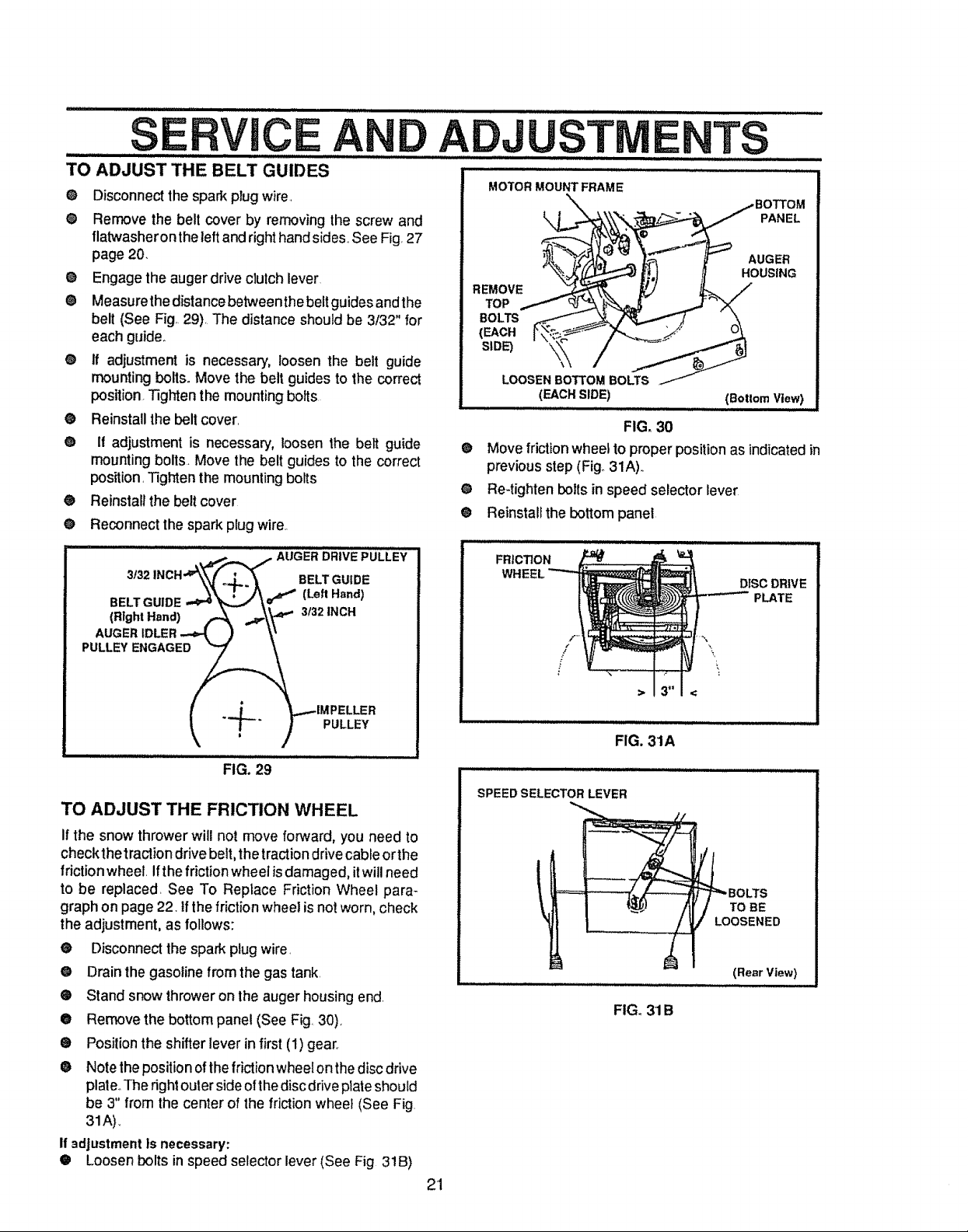
TO ADJUST THE BELT GUIDES
e
Disconnect the spark plug wire,
e
Remove the belt cover by removing the screw and
flatwasheron the leftandright handsides, See Fig,27
page 20,
e
Engage the auger drive clulch lever
e
Measurethe distance between the beltguides andthe
belt (See Fig. 29), The distance should be 3/32" for
each guide.,
@
if adjustment is necessary, loosen the belt guide
mounting bolts° Move the belt guides to the correct
position. Tighten the mounting bolts
@
Reinstall the bell cover,
o
If adjustment is necessary, loosen the belt guide
mounting bolts, Move the belt guides to the correct
position, Tighten the mounting bolts
®
Reinstall the belt cover
O
Reconnect the spark plug wire.,
ADJU TM
MOTOR MOUNT FRAME
k PANEL
REMOVE
TOP
BOLTS
(EACH
SIDE)
\
LOOSEN BOTTOM BOLTS
(EACH SIDE) (Botlom View)
®
Movefrictionwheeltoproperpositionas indicatedin
previousstep (Fig°31A).,
O
Re-tightenbelts in speed selector level
®
Reinstallthe bottom panel
,Lij /i / /J,. .................
FIG. 30
TS
AUGER
HOUSING
.... _ _,,_f..._./1 AUGER DRIVE PULLEY
BELTO0,D
wtg.,.o.,) ,=,NO.
if .._.L_.. _.._IMPELLER
It` {--" ) PULLEY
FIG. 29
TO ADJUST THE FRICTION WHEEL
If the snow thrower willnot move forward, you need to
check thetraction drive belt, the traction drive cableorthe
frictionwheel Ifthe friction wheeiis damaged, itwill need
to be replaced, See To Replace Friction Wheel para-
graph on page 22 tf the friction wheel is notworn, check
the adjustment, as follows:
@ Disconnect the spark plug wire,
@ Drain the gasoline from the gas tank,
• Stand snow throweron the auger housing end.
@ Remove the bottom panel (See Fig.,30).
• Position the shifter lever in first (1) gear.
• Note the position ofthe frictionwheel on thedisc drive
plate,.The rightouter sideofthe disc driveplateshould
be 3" from the center of the friction wheel (See Fig.
31A),
If 3dJustmentIs necessary:
• Loosen bolts in speed selector lever (See Fig 31B)
FRICTION
DISC DRIVE
PLATE
FIG. 31A
SPEEDSELECTOR LEVER
BOLTS
TO BE
OOSENED
(RearView t
FIG. 3'1B
21
.qFRVICF AND A_r}JUSTMENFS
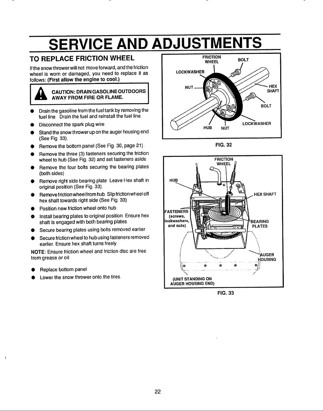
TO REPLACE FRICTION WHEEL
Ifthe snowthrower will notmoveforward,andthefriction
wheel is worn or damaged, you need to replace it as
follows: (First allow the engtne to cool.)
AWAY FROM FIRE OR FLAME, !
• Drainthe gasoline fromthefueltank by removing the
fuel line Drain the fuel and reinstall the fuel line.
• Disconnect the spark plug wire
• Stand the snow thrower up on the auger housing end
(See Fig 33).,
• Rerr_ve the bottom panel (See Fig,,30, page 21).
® Remove the three (3) fasteners securing the fnction
wheel to hub (See Fig..32) and set fasteners aside
• Remove the four bolts securing the bearing plates
(both sides)
• Remove right side bearing plate Leave Hex shaft in
original position (See Fig..33).
® Rernovefdction wheetfrom hub Slipfrictionwheel off
hex shaft towards right side (See Fig 33)
• Position new friction wheel onto hub,
• Install bearing plates to original position Ensure hex
shaft is engaged with both bearing plates,
• Secure bearing plates using bolts removed earlier.
• Secure frictionwheel to hub using fasteners removed
earlier. Ensure hex shaft turns freely,
NOTE: Ensure frictionwheel and friction disc are free
from grease or oil.
• Replace bottom panel
• Lowerthe snow throwerontothetires
FR|CTION
WHEEL BOLT
LOCKWABHER
BOLT
HUB NUT
LOCKWASHER
FIG. 32
FRICTION
HUB
HEX SHAFT
FASTENERS
(screws,
Iockwashers RING
and nuts) PLATES
; "\
0 • //
i,.................................................................... ous,NG
(UNIT STANDING ON
AUGER HOUSING END)
j Hi,ll ===ul,Jlu
FIG. 33
HEX
SHAFT
22
 Loading...