

Craftsman 536886531 Owner’s Manual
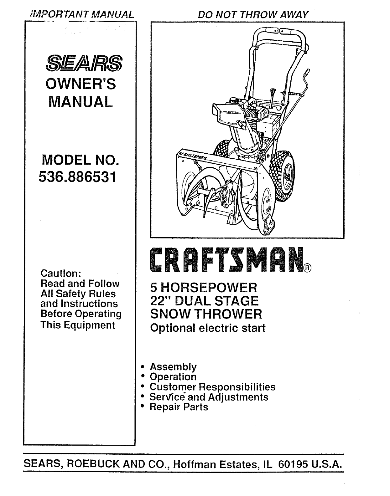
"MPORTANT MANUAL
OWNER'S
MANUAL
MODEL NO.
536.886531
DO NOT THROW AWAY
Caution:
Read and Follow
All Safety Rules
and Instructions
Before Operating
This Equipment
®
5 HORSEPOWER
22" DUAL STAGE
SNOW THROWER
Optional electric start
• Assembly
• Operation
• Customer Responsibilities
° Servlc_ and Adjustments
• Repair Parts
,,=,=,,=,,= ,=,
SEARS, ROEBUCK AND CO., Hoffman Estates, IL 60195 U.S.A.
= 11 11 11 ,=H ,,,,HH= ,H 111 11,11,1=,==,=H= 11 1111
SAFETY RULES
_ CAUTION. ALWAYS DISCONNECT SPARK PLUG WIRE AND _li
PLACE WIRE WHERE IT CANNOT CONTACT SPARK PLUG
TQ PREVENT ACCIDENTAL STARTING WHEN SETTING-UP,
TRANSPORTING, ADJUSTING OR MAKING REPAIRS,
IMPORTANT
SAFETY STANDARDS REQUIRE OPERATOR PRESENCE CONTROLS TO MINIMIZE THE
RISK OF INJURY. YOUR SNOW THROWER IS EQUIPPED WITH SUCH CONTROLS. DO NOT
ATTEMPT TO DEFEAT THE FUNCTION OF THE OPERATOR PRESENCE CONTROL UNDER
ANY CIRCUMSTANCES.
TRAINING
1. Read the operator's manual carefully. Be
thoroughly familiar with the controls and the
proper use of the snow thrower. Know how to
stop the snow thrower and disengage the
controls quickly.
2. Never allow children to operate the snow thrower
and keep them away while it is operating. Never
allow adults to operate the snow th rower without
proper instruction. Do not carry passengers.
3. Keep the area of operation clear of all persons,
particularly small children, and pets_
4. Exercise caution to avoid slipping or falling,
especially when operating in reverse.
PREPARATION
1. Thoroughly inspect the area where the snow
thrower is to be used and remove all doormats,
sleds, boards, wires, and other foreign objects.
2. Disengage all clutches and shift into neutral
before starting the engine (motor).
3. Do not operate the snow thrower without wearing
adequate winter outer garments° Wear footwear
that will improve footing on slippery surfaces,
4, Handle fuel with care; it is highly flammable.
(a) Use an approved fuel container.
(b) Never remove fuel tank cap or add fuel to a
running engine or hot engine.
(c) Fill fuel tank outdoors with extreme care.
Never fill fuel tank indoors.
(d) Replace fuel tank cap securely and wipe up
spilled fuel.
(e) Never store fuel or snow thrower with fuel in
thetank insideof abuilding where fumes may
reach an open flame or spark.
(f) Check fuel supply before each use, allowing
space for expansion as the heat of the engine
(motor) and/or sun can cause fuelto expand.
,
Use extension cords and receptacles as specified
by the manufacturer for all snow throwers with
electric drive motors or electric starting motors
6_ Adjust the snow thrower height to clear gravel or
crushed rock surfaces.
7o Never attempt to make any adjustments while the
engine (motor) is running (except when
specifically recommended by the manufacturer).
8, Let engine (motor) and snow thrower adjust to
outdoor temperatures before starting to clear
snow.
9. Always wear safety glasses or eye shields during
operation or while performing an adjustment or
repair to protect eyes from foreign objects that
may be thrown from the snow thrower.
OPERATION
1. Do not put hands or feet near or under rotating
parts° Keep clear of the discharge opening at all
times,,
2. Exercise extreme caution when operating on or
crossing gravel drives, walks, or roads. Stay alert
for hidden hazards or traffic.
3. After striking a foreign object, stop the engine
(motor), remove the wire from the spark plug,
disconnect the cord on electric motors,
thoroughly inspect the snow thrower for any
damage, and repair the damage before restarting
and operating the snow thrower.
4, If the snow thrower should start to vibrate
abnormally, stop the (motor) and check
immediately forthe cause_ Vibration is generally
a warning of trouble°
5. Stop the engine (motor) whenever you leave the
operating position, before unclogging the auger/
impeller housing or discharge guide, and when
making any repairs, adjustments, or inspections.
When cleaning, repairing, or inspecting, make
certain the auger/impeller and all moving parts
have stopped. Disconnect the spark plug wire
and keep the wire away from the plug to prevent
accidental starting°
7 Take all possible precautions when leaving the
snow thrower unattended. Disengage the auger/
impeller, shift to neutral, stop engine, and
remove key.
SAFETY RULES
8. Do not runthe engine indoors, except when starting
the engine and for transporting the snow thrower in
or out of the building. Open the outside doors;
exhaust lumesaredangerous (containing CARBON
MONOXIDE, an ODORLESS and DEADLY GAS).
9. Do not clear snow across the face of slopes.
Exercise caution when changing direction on
slopes. Do not attempt to clear steep slopes.
10. Never operate the snow thrower without proper
guards, plates or other safety protective devices
in place.
11. Never operate the snow thrower near glass
enclosures, automobiles, window wells,
drop-oils, and the like without properadjustment
of the snow discharge angle. Keep children and
pets away.
12. Do not overload the machine capacity by
attempting to clear snow at too fast a rate.
13o Never operate the snowthrower at high transport
speeds on slippery surfaces. Look behind and
use care when backing°
t4. Never direct discharge at bystanders or allow
anyone in tront of the snow thrower.
15. Disengage power to the auger/impeller when
snow thrower is transported or not in use.
16. Useonly attachments and accessories approved
by the manufacturer of the snow thrower (such
as tire chains, electric start kits, etc.).
17. Never operate the snow thrower without good
visibility or light. Always be sure of your footing,
and keep a firm hold on the handles. Walk; never
rug.
MAINTENANCE AND STORAGE
1. Check shear bolts and other bolts at frequent
improper tightness to be sure the snow thrower
is in safe working condition.
2. Never store the snow throwerwith fuel inthe fuel
tank inside a building where ignition sources are
present such as hot water and space heaters,
clothes dryers, and the like. Allow the engine to
cool before storing in any enclosure.
3. Always refer to operator's manual instructions
for important details if the snow thrower isto be
stored for an extended period°
4. Maintain or replace safety and instruction labels,
as necessary.
5o Run the snow thrower a few minutes after
throwing snow to prevent freeze-up of the auger/
impelter_
WARNING ...................
This snow thrower is for use on sidewalks,
driveways, and other ground level surfaces.
CAUTION should be exercised while using on
steep sloping surfaces. DO NOT USE SNOW
THROWER ON SURFACES ABOVE GROUND
LEVEL such as roofs of residences, garages,
porches or other such structures or buildings,
.................. ,,, i Hl,ll,ll,,,
I _ LOOK FOR THIS SYMBOL TO POINT OUT
! A IMPORTANT SAFETY PRECAUTIONS. IT
!,_ MEANS--ATTENTION!!! BECOMEALERT!!!
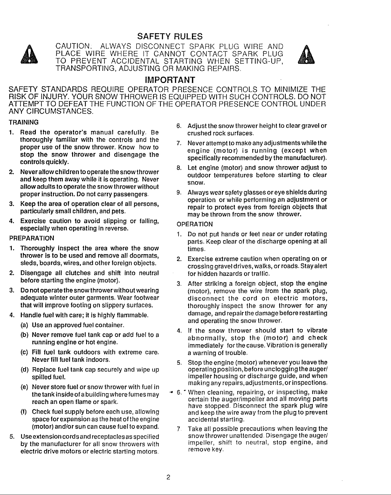
CAUTION: STOP THE
ENGINE BEFORE
UNCLOGGING
%DISCHARGE CHUTE.Lj
,..===., YOUR SAFETY IS INVOLVED.
• ................................... i iiiii
,=
CONGRATULATIONS on your purchase of a Sears
Craftsman Snow Thrower It has been designed, engi-
neered and manufactured to give you tfTebest possible
dependability and performance
Should you experience any problem you cannot easily
remedy, please contact your nearest Sears Service
Center/Department Sears has competent, well-trained
technicians and the proper tools to service or repair this
unit
Ptease read and retain this manual The instructions will
enable you to assemble and maintain your snow thrower
properly, Always observe the "SAFETY RULES,"
H i iHl,, ,,Hn
MODEL
NUMBER 536 886531
SERIAL
NUMBER
DATE OF'--_
PURCHASE
THE MODELAND SERtAL NUMBERS WILL BE
FOUND ON A DECAL ATTACHED TO THE REAR
OF THE SNOW THROWER HOUSING
YOU SHOULD RECORD BOTH SERIAL NUMBER
AND DATE OF PURCHASE AND KEEP tNA SAFE
PLACE FOR FUTURE REFERENCE
PRODUCT SPECIFICATIONS
u,,,, ,, i,iH ,,,, i, i , u, ,,H,,, , i,,,,H, ,,H,
HORSE POWER: 5 hp
DISPLACEMENT: 12.04
cu. in.
GASOLINE CAPACITY: 2 quarts
Unleaded
HH, IIII1,1 H I ,,,, ,.
OIL (21 oz. Capacity): SAE 5W-30
SPARK PLUG : Champion
(GAP .030 in.) RJ19LM
HHn,HH H IHHH nil,,,
VALVE CLEARANCE: Intake: .010 In.
Exhaust: .010 In_
i Hm,H,, I " I'
MAINTENANCE AGREEMENT
A Sears Maintenance Agreement is available on this
product Contact your nearest Sears Store for details
CUSTOMER RESPONSIBILITIES
• Read and observe the safety rules
• Follow a regular schedule in maintaining, caring for and using your snow thrower
a FolIow the instructions under "Customer Responsibilities" and "Storage" sections of this owner's manual,,
HH, H,,' ......................... , HHH H',,' ! nHHH I H, HI HHHn" I,"l
TWO YEAR LIMITED WARRANTY ON CRAFTSMAN
SNOW THROWER
For two years from the date of purchase, when this Craftsman Snow Thrower is maintained, lubricated
and luned_up according to the instructions in the owner's manual, Sears will repair, free of charge, any
defect in material and workmanship
tf this Craftsman Snow Thrower is used for commercial or rental purposes, this warranty applies for only
90 days from the date of purchase
This warranty does not cover the following:
* Expendable items which become worn during normal use, such as spark plugs, drive belts and shear
pins
* Repairs necessary because of operator abuse or negligence, including bent crankshafts and the failure
to maintain the equipment according to the instructions contained in the owner's manual
WARRANTY SERVICE IS AVAILABLE BY RETURNING THE CRAFTSMAN SNOW THROWER TO THE
NEAREST SEARS SERVICE CENTER/DEPARTMENT IN THE UNITED STATES TH1SWARRANTY
APPLIES ONLY WHILE THIS PRODUCT IS IN USE tN THE UNITED STATES
This warranty gives you specific legal rights, and you may also have other rights which may vary from
state to state
SEARS, ROEBUCK AND CO Deparlment 731CR-W, Hoflman Estates, IL 60195
........................................ , i,, HH I , HHH, HI H I
4
TABLE OF CONTENTS
SAFETY RULES ................................................2,3
PRODUCT SPECIFICATIONS ...............................4
CUSTOMER RESPONSIBILITIES ......4,15,16
WARRANTY ......................................................... 4
TABLE OF CONTENTS .......................................5
INDEX .........................................................................5
ASSEMBLY .........................................................6-9
OPERATION .................. ................................... t 0-14
SERVICE AND ADJUSTMENTS ........... 17-23
STO RAG E ..............................................................24
SERVICE RECOMMENDATIONS .....................25
TROUBLE SHOOTING .................................... 26
REPAIR PARTS (SNOW TH ROWER)co. 28-37
REPAIR PARTS (ENGINE) ................................38-42
PARTS ORDERINGISERVlCE ........Back Cover
INDEX
A
Adjustment:
Belt ...................................................18,19
Bell Guide ...........................................20
Cable ...........................................................18
Carburetor ...........................................13,22
Friction Wheel ....................................20,2t
Spark Plug .................................................23
Traction and Auger .................... 18,19
Assembly:
Crank Assembly ............................................ 8
Shifter Lever ....................................................9
Skid Height Adjustment ..................7, 17
Unpacking ....................................... 7
B
Belts:
Adjust Belts ........................ 18,19
Belt Guide Adjustment ............ 20
Replace Belts ............................... 19
C
Cables, Clutch ......................... 7, 9, 18
Carburetor: ........................................13,24
Choke ............................ 10, 11, 13
Clutch, Levers ........................... 10, 11
Controls:
Engine ............................ 10, 11, t3, t4
Snow Thrower ............................ 10
Crank:
Adjusting Rod ...................... 8, 17
Assembly ........................................... 8
Operation ................................... 11
Customer Respo nsibilities .........4,15,16
Agreement .................................. 4
Auger Gear Box .................... 16
Auger Shaft .................................. 15
Engine ........................................ 16
General Recommendations ........ 15
Hex Shaft and Gears .................... 16
D
Drive, Auger ............................. 11
Drive, Traction ......................... 11
Deflector, Snow Chute .................. 1t
E
Engine:
Conlrol .......................... t0, 1t, 13, 14
Oil Cap ....................... t2, 16
Oil Change .......................... 16
Oil Level ...................... 12, 16
Oil Type .......................... 4, 12, 16
Speed Governor ............... 24
Starting, Manually ................. 13
Storage .................................... 24
F
Fuel, Type ............................. 4, 12
Fuel, Storage .......................................12, 24
Friction Wheel:
Adjustment ........................................ 20
Replacement ................................. 21
G
Gears:
Auger Gear Box ............................... 16
Hex Shaft .............................................16
H
Handle, Upper and Lower ..........................7
Height Adjust Skids ...............................7, 17
Hex Shaft .........................................................t 6
i
Ignition, Key .................. 10, 11,13, 14
Index .......................... 5
L
Levers:
Auger Drive Clutch ........7, 10, 11, 18
Choke ...................... 10, 11,13, 14
Shifter ................................... 9, 10, 11
ThrOttle Control ........... 10, l 1,13, t 4
Traction Drive Clutch .... 7, 10, 11, 18
Lubrication:
Auger Gear Box .......................... 18
Auger Shaft ................... 15
Chart .................................... 25
Disc Drive Plate ......................... 15
Engine ................................. t2,!6,24
Flex Shaft and Gears ................ 16
O
Oi!:
Engine .....................................4, 12, 16
Extreme Cold Weather .............. 12,16
Storage ....................................... 24
Type ....................... 4, I2, I6
Operation:
Carburetor .................. 13
Engine Controls .......... 10, 11, !3,14
Operating 9now Thrower 11, 12, 15
Lockout Pin, Wheel ................... 12
Operating Tips ...................... 14
Starting the Engine, Recoil ........ 13
Snow Thrower Controls ......... 10-12
P
Parts .............................. 28-42
Primer Bulton ........... 10, 1t, 13
R
Repair/Replacement Parts ...... 28-42
Recoil Starter .......................... 13
Replacements:
Auger Shear Boil ...............................22
Belts ............................................. 18,19
Friction Wheel ..............................20,21
Safety Rules .........................................2, 3
Service and Adjustments:
Auger Housing Height .............. 7, 17
Auger Shear Bolt ............................. 22
Belts ........................................... 18-19
Belt Guide ......................................... 20
Belt Replacements .............................19
Cable ...................................... 7, 9, 18
Carburetor ............................ 13,22, 24
Friction Wheel ................. 20, 2t
Spark Plug ................................... 23
Service Recommendations ............ 24
Spark Plug ................................. 16, 23
Specifications ......................... 4
Speed Governor .......................... 22
Starting the Engine:
Recoil Start ........................................ 13
Stopping the Engine ................ 13, ! 4
Stopping the Snow Thrower ............. 11
Shipping Carton .............................. 6, 7
Skid Height .................................. 17
Shifter Lever ......................... 9-11
Shear Bolts ....................... 22
Storage ................................ 24
Table of Contents ......................... 5
Trouble Shooting Chart .................... 26
Tools for Assembly .......................... 6
Traction Drive Belt ................. 18, I9
Tire Pressure ..................... 17
Warranty ..................................... 4
Wheel, Lockout Pin ........ !2
S
T
W
ASSE LY
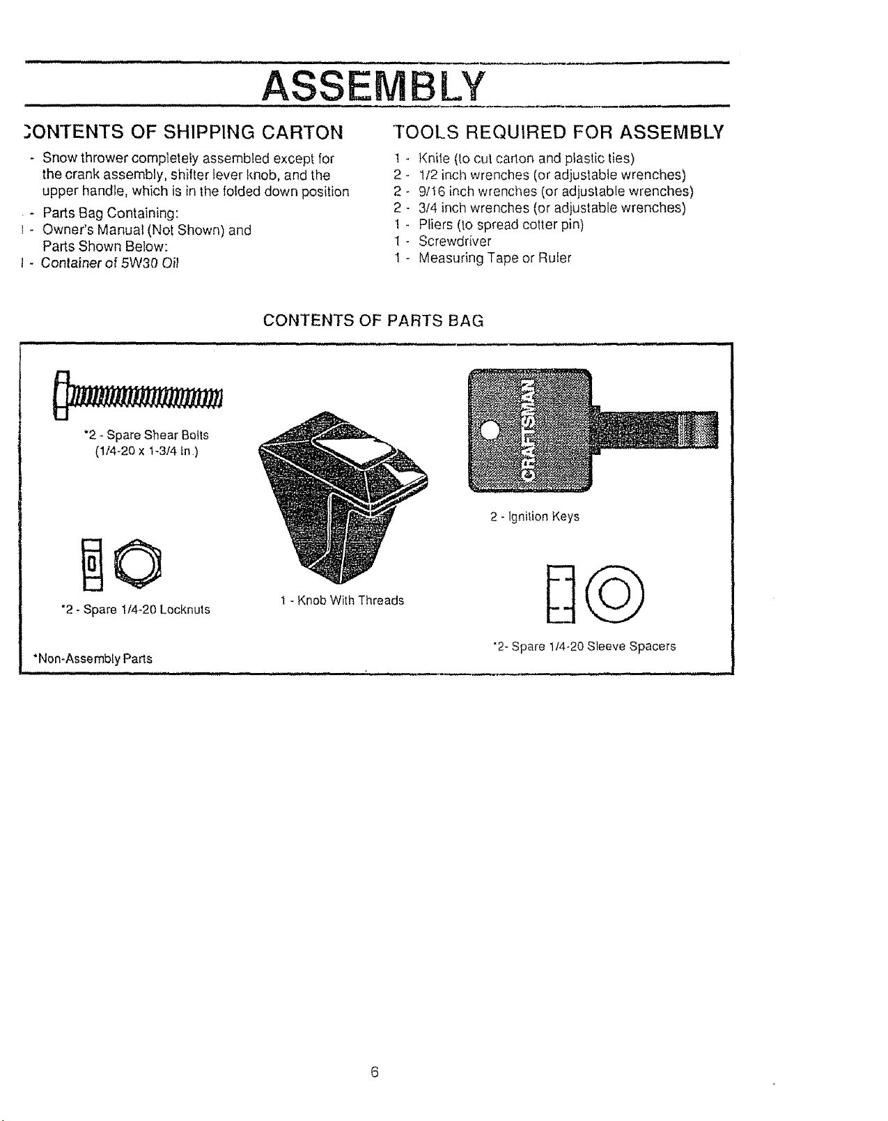
.,?,ONTENTS OF SHIPPING CARTON TOOLS REQUIRED FOR ASSEMBLY
- Snow thrower complelely assembled except for t
the crank assembly, smiter lever knob, and the 2
upper handle, which is in the folded down position 2
- Parts Bag Containing: 2
- Owner's Manual (Not Shown) and 1
Parts Shown Below: 1
- Conlainer of 5W30 Oil 1
CONTENTS OF PARTS BAG
*2 -Spare Shear Bolts
(1t4-20 x t-3/4 tn)
Kniie (to cut cadon and plastic ties)
1/2 inch wrenches (or adjustable wrenches)
9/16 inch wrenches (or adjustable wrenches)
3/4 inch wrenches (or adjustable wrenches)
Pliers (to spread cotter pin)
Screwdriver
Measuring Tape or Ruler
2 - ignition Keys
"2- Spare 1t4-20 Lecknuts
1 - Knob With Threads
"Non-Assembly Parts
nn n,u,,, H,u m,,,,,, i, , i ,,,,,,,,,,iu ' , ,, ,i .
"2-Spare t14-20Sleeve Spacers
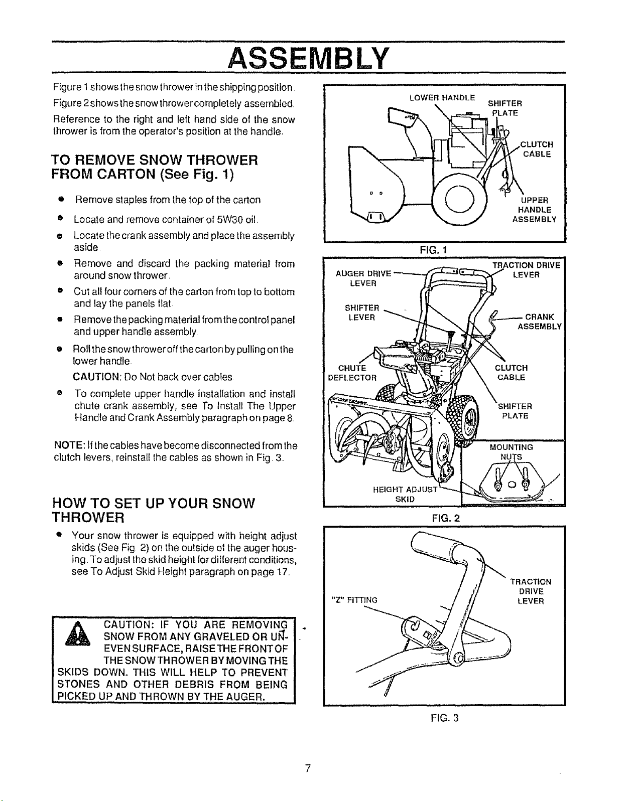
Figure1showsthesnowthrowerinthe shipping position
Figure 2shows thesnow thrower completely assembled
Reference to the right and left hand side of the snow
thrower is from the operator's position at the handle.
TO REMOVE SNOW THROWER
FROM CARTON (See Fig. 1)
• Remove staples from the top of the carton
• Locate and remove container of 5W30 oil.
• Locatethe crank assembly and place the assembly
aside
o Remove and discard the packing material from
around snow thrower
o Cut all four corners of the carton from top to bottom
and lay the panels flat
= Remove the packing material fromthe control panel
and upper handle assembly
• Rollthe snowthrower off the carton by pulling onthe
lower handle+
CAUTION: Do Not back over cables
® To complete upper handle instaltation and install
chute crank assembly, see To Install The Upper
Handle and Crank Assembty paragraph on page 8
CABLE
UPPER
HANDLE
ASSEMBLY
ii iin,,
FIG. 1
NOTE: If the cables have become disconnected from lhe
clutch levers, reinstall the cabfes as shown in Fig, 3.
HOW TO SET UP YOUR SNOW
THROWER
Your snow thrower is equipped with height adjust
skids (See Fig 2) on the outside ot the auger hous-
ing. To adjust the skid height fordifferent conditions,
see To Adjust Skk:l Height paragraph on page 17+.
" CAUTION: IF' YO'U'"'ARE 'R'E'r_0VING
SNOW FROM ANY GRAVELED OR UJ_-
EVEN SURFACE, RAISETHE FRONTOF
THE SNOW THROWER BY MOVING THE
SKIDS DOWN+ THIS WILL HELP TO PREVENT
STONES AND OTHER DEBRIS FROM BEING
PICKED UP AND THROWN BY THE AUGER.
"Z" FITTING
FIG. 2
TRACTION
DRIVE
LEVER
7
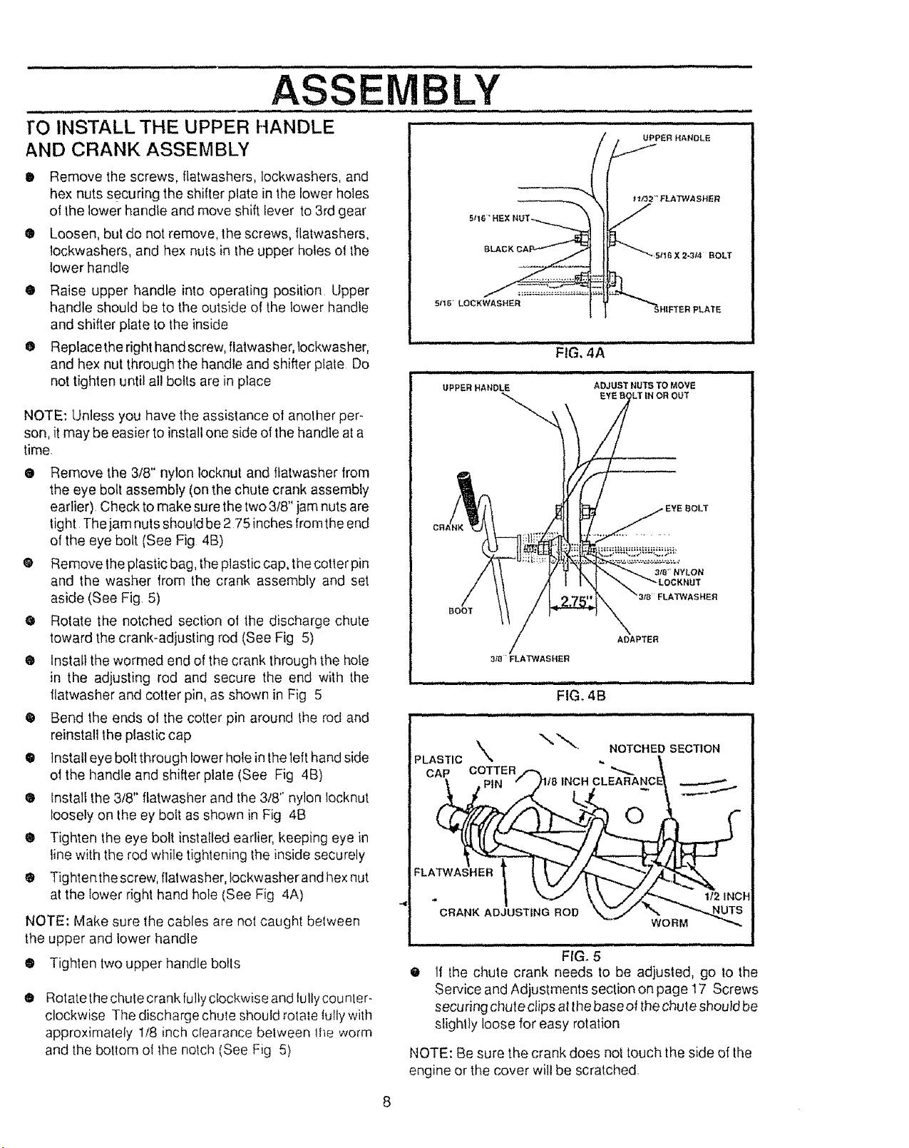
ASSEMBLY
,,,, ,,,, - ,,,,,,, ,,,,
rO INSTALL THE UPPER HANDLE
AND CRANK ASSEMBLY
• Remove the screws, flatwashers, lockwashers, and
hex nuts securing the shitter plate in the lower holes
of the lower handle and move shift lever to 3rd gear
® Loosen, but do not remove, the screws, flatwashers,
lockwashers, and hex nuts in _heupper holes ol the
lower handle
® Raise upper handle into operating position Upper
handle should be to the outside of the lower handle
and shifter prate to the inside
O Replacethe right hand screw, flatwasher, lockwasher,
and hex nut through the handle and shifter plate Do
not tighten t_ntilall bolts are in place
NOTE: Unless you have the assistance of another per-
son, it may be easier toinstall one side ot the handle at a
time.
@ Remove the 3/8" nylon locknut and flatwasher from
the eye bolt assembly (on the chute crank assembly
earlier) Check to make sure thetwo 3/8" jam nuts are
tight The jam nuts should be 275 inches fromthe end
of the eye bolt (See Fig 4B)
@ Remove the plastic bag, the plastic cap, the cotter pin
and the washer from the crank assembly and set
aside (See Fig 5)
@ Rotate the notched section of the discharge chute
toward the crank-adjusting rod (See Fig 5)
® Install the wormed end of the crank through the hofe
in the adjusting rod and secure the end with the
llatwasher and cotter pin, as shown in Fig 5
• Bend the ends of the cotter pin around the rod and
reinstall the plastic cap
@ Instal] eye bolt through lower hole in the left hand side
ot the handle and shifter plate (See Fig 4B)
® tnstall the 3/8" flatwasher and the 3/8" nylon locknut
loosely on the ey bolt as shown in Fig 4B
® Tighten the eye bolt installed earlier, keeping eye in
line with the rod while tightening the inside securely
® Tightenthe screw, flalwasher, Iockwasherand hex nut
at the lower right hand hole (See Fig 4A)
NOTE: Make sure the cables are not caught between
the upper and lower handle
O Tighten two upper handle bolts
O
Rotate the chute crank fully clockwise and lultycounler-
clockwise The discharge chule should rotale tully with
approximately 1/8 inch ctearance belween ihe worm
and the bottom ot the notch (See Fig 5)
FTER PLATE
FLATWASHER
BOOT
ADAPTER
3_FLATWASHER
i i i,,,,, n, ,nil n,,i,ii nnl
FIG, 4B
PLASTIC
CAP COTTER/-
FLA_.
CRANK ADJUSTING ROD
)118 INCH
NOTCHED SECTION
;LEARANC_
....................
@
If the chute crank needs to be adjusted, go to the
Service and Adjustments section on page 17 Screws
securing chute clips atthe base of thechule should be
slight}y loose for easy rotation
NOTE: Be sure the crank does not touch the side of the
engine or the cover wilt be scratched,
...............ASSEMBLY ...............
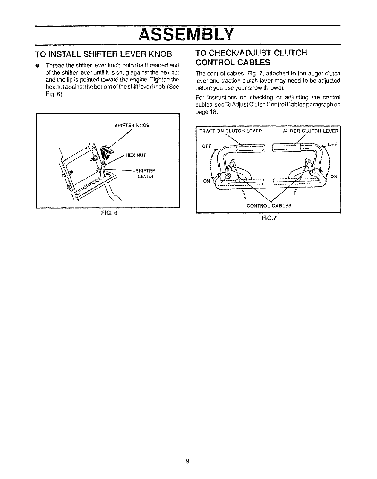
TO INSTALL SHIFTER LEVER KNOB
• Thread the shifter lever knob onto the threaded end
ol the shilter lever until it is snug against the hex nut
and the lip is pointed toward the engine Tighten the
hex nut against the botlom o! the shift lever knob (See
Fig 6)
SHIFTER KNOB
""_"_'\ __H EX N U T
HEX
_._. LEVER
F,GI'6"'
TO CHECKJADJUST CLUTCH
CONTROL CABLES
The control cables, Fig. 7, attached to the auger clutch
lever and traction clutch lever may need to be adjusted
belore you use your snow thrower
For instructions on checking or adjusting the control
cables, see ToAdjust Clutch Control Cables paragraph on
page 18
TRACTION CLUTCH LEVER AUGER CLUTCH LEVER
OFF __ FF
I I,ft- _ ]] ]
, .......... ON
CONTROL CABLES
FIG.7
.................. r , HHH'""t' ''"""1' __" ..... ' '"""L.......... -
OPERATION
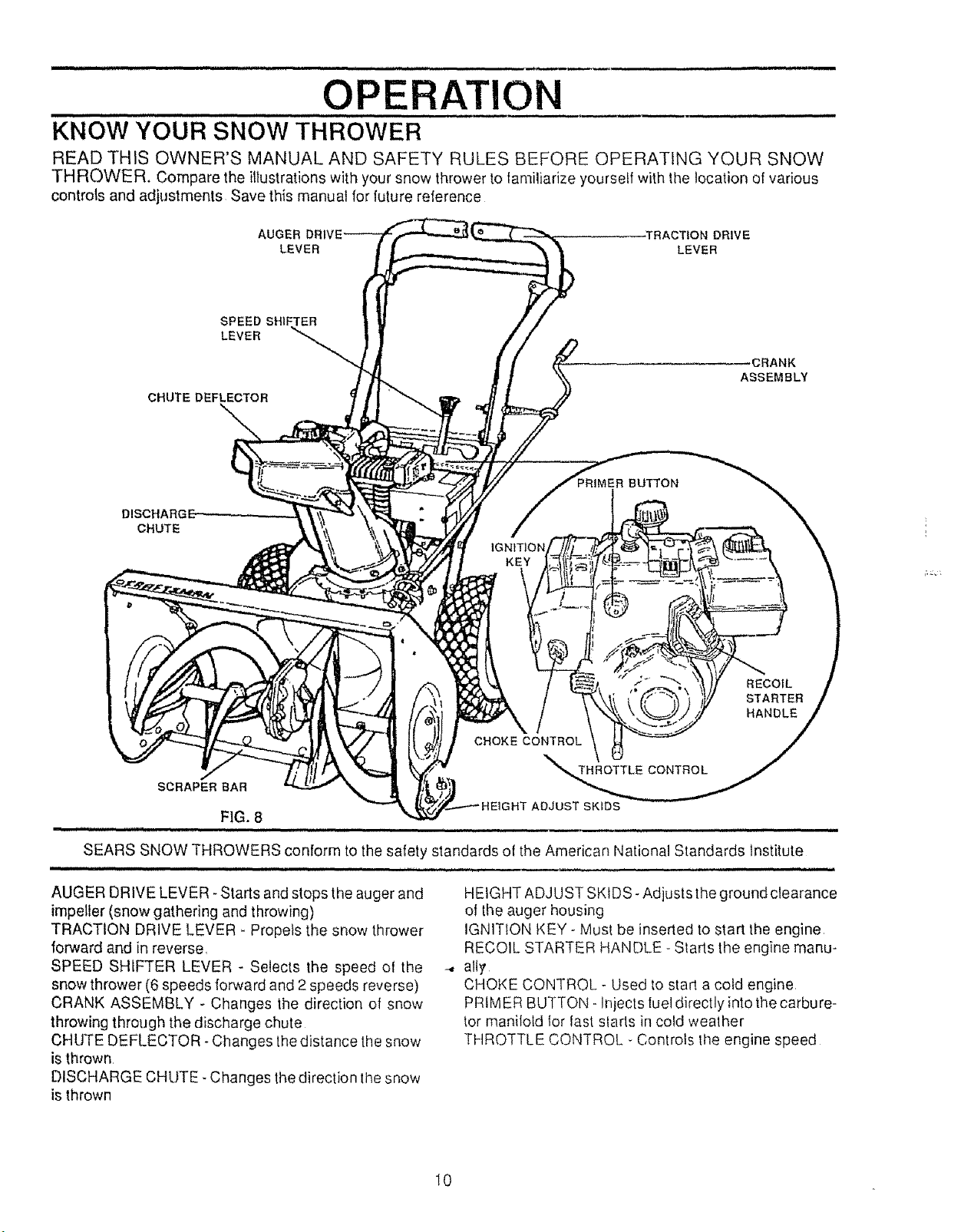
KNOW YOUR SNOW THROWER
READ THIS OWNER'S MANUAL AND SAFETY RULES BEFORE OPERATING YOUR SNOW
THROWER. Compare the illustrations with your snow thrower to tamiliarize yourself with the location of various
controls and adjustments Save this manual for luture reference
AUGER -TRACTION DRIVE
LEVER LEVER
SPEED SHIFTER
LEVER
_CRANK
ASSEMBLY
CHUTE DEFLECTOR
_BUTTON
CHUTE
SCRAPER BAR
n l m,un,,, ,nil,,, ,U,,,H , nH ,,H,',,,',' , ,.,P..
FIG. 8
SEARS SNOW THROWERS conform to the safety standards of the American National Standards Institute
AUGER DRIVE LEVER- Starts and stops the auger and
impeller (snow gathering and throwing)
TRACTION DRIVE LEVER - Propels the snow thrower
forward and in reverse,
SPEED SHIFTER LEVER - Selects the speed of the
snow thrower (6 speeds forward and 2speeds reverse)
CRANK ASSEMBLY - Changes the direction of snow
throwing through the discharge chute
CHUTE DEFLECTOR- Changes the distance the snow
HEIGHT ADJUST SKIDS- Adjusts the ground clearance
of the auger housing
IGN1TION KEY - Must be inserted to start the engine
RECOIL STARTER HANDLE - Starts the engine manu-
--. alI_
CHOKE CONTROL - Used to start a cold engine
PRIMER BUTTON- Injects luel directly into the carbure-
tor manilotd for last slarts in cold weather
THROTTLE CONTROL - Controls the engine speed
is thrown
DISCHARGE CHUTE. Changes the direction the snow
is thrown
10
OPERATION
u J,,J i
The operation ot any snow thrower can result in foreign objects being thrown into the
eyes, which can result in severe eye damage Always wear safety glasses or eye
shields while operating the snow thrower
We recommend standard safety glasses available at SEARS Retail or Catalog
Stores or a wide vision safety mask !or over your glasses
iii i i, ,1,,1, ,,,,,i , t
HOW TO USE YOUR SNOW
THROWER
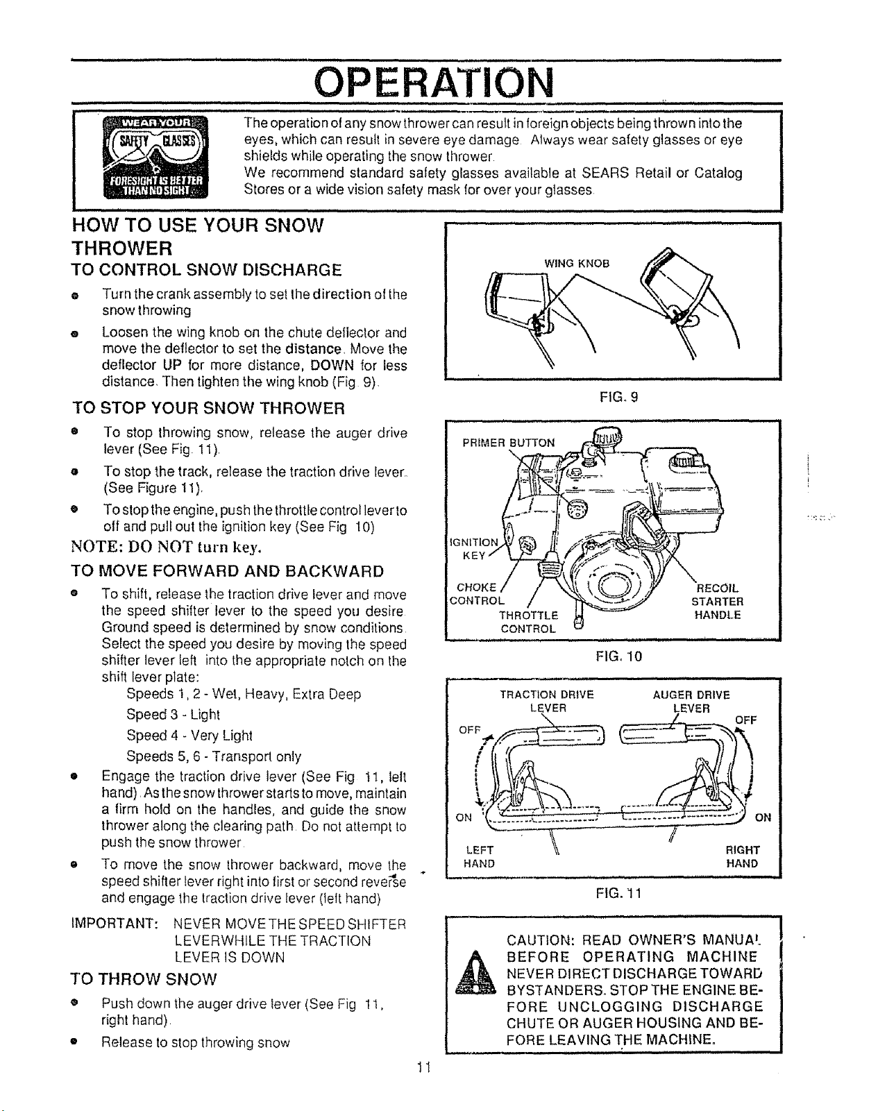
TO CONTROL SNOW DISCHARGE
® Turn the crank assemMy to set the direction ol the
snow throwing
® Loosen the wing knob on the chute deflector and
move the deflector to set the distance. Move the
deflector UP for more distance, DOWN for less
distance. Then tighten the wing knob (Fig 9)
TO STOP YOUR SNOW THROWER
• To stop throwing snow, release the auger drive
lever (See Fig. 11)
o To stop the track, release the traction drive Iever.
(See Figure 11).
• To stop the engine, push the throttle control lever to
off and pull out the ignition key (See Fig 10)
NOTE: DO NOT turn key.
TO MOVE FORWARD AND BACKWARD
o To shift, release the traction drive lever and move
the speed shifter lever to the speed you desire
Ground speed is determined by snow conditions
Select the speed you desire by moving the speed
shifter lever left into the appropriate nolch on the
shift lever plate:
Speeds 1,2 - Wet, Heavy, Extra Deep
Speed 3 - Light
Speed 4 - Very Light
Speeds 5, 6- Transport only
• Engage the traction drive lever (See Fig I1, lelt
ha nd) As the snow thrower starts to move, maintain
a firm hold on the handles, and guide the snow
thrower along the clearing path Do not attempt to
push the snow thrower
e To move the snow thrower backward, move the
speed shifter lever right into first or second reverse
and engage the traction drive lever (left hand)
IMPORTANT: NEVER MOVETHESPEEDSHfFTER
LEVERWHILE THE TRACTION
LEVER IS DOWN
TO THROW SNOW
• Push down the auger drive lever (See Fig 1I,
right hand)
• Release to stop throwing snow
-,d
WING KNOB
FIG_ 9
FIG, 10
,,,q,,, 1,1,, ,
TRACTION DRIVE
LEVER
LEFT RIGHT
HAND HAND
AUGER DRIVE
_EVER
OFF
ON
FIG. 11
CAUTION: READ OWNER'S MANIJA'.
NEVER DIRECT DISCHARGE TOWARD
BEFORE OPERATING MACHINE
BYSTANDERS. STOP THE ENGINE BE-
FORE UNCLOGGING DISCHARGE
CHUTE OR AUGER HOUSING AND BE-
FORE LEAVING THE MACHINE°
- ,m ,,,, , , ,, i , ,, i I,H,,H, I I I
1I
OPERATION
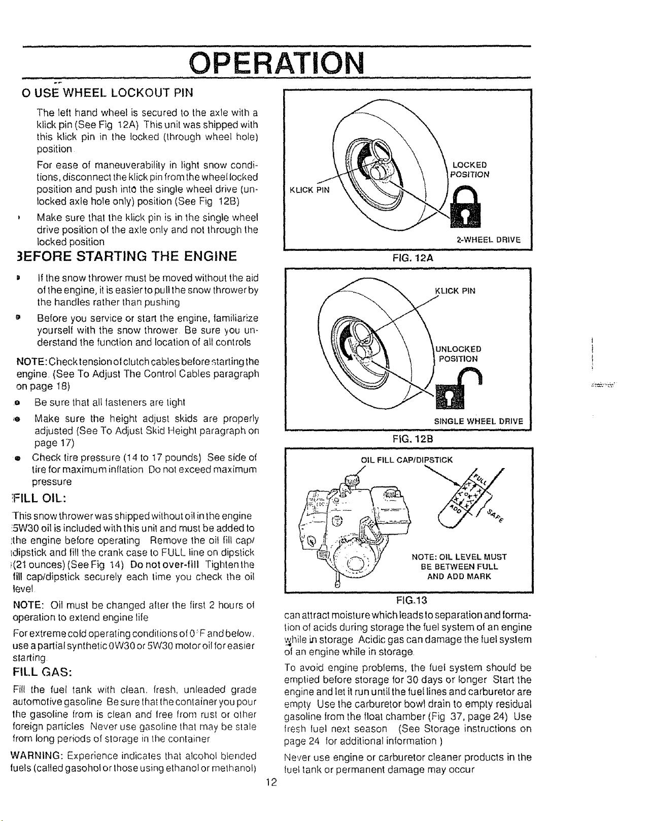
O USE WHEEL LOCKOUT PIN .................
The lett hand wheel is secured to the axle with a
klick pin (See Fig 12A) This unit was shipped with
this klick pin in the locked (through wheel hole)
position
For ease of maneuverability in light snow condi-
lions, disconnect the klick pin from the wheel locked
position and push into the single wheel drive (un-
locked axle hole only) position (See Fig 12B)
, Make sure that the klick pin is in the single wheel
drive position ol the axle only and not through the
locked position
3EFORE STARTING THE ENGINE
D If the snow thrower must be moved without the aid
of the engine, itis easier to pultthe snow thrower by
the handles rather than pushing
a, Before you service or start the engine, familiarize
yourself with the snow thrower Be sure you un-
derstand the function and location of all controls
NOTE: Check tension ot clutch cables before._tarting the
engine (See To Adjust The Control Cables paragraph
on page 18)
.o Be sure that all lasteners are tight
,o Make sure the height adjust skids are properly
adjusted (See To Adjust Skid Height paragraph on
page 17)
e Check tire pressure (I4 to t7 pounds) See side of
tire for maximum inflation Do not exceed maximum
pressure
;FILL OIL:
KUCK PIN
. ill, i
i,, iiJJ. ,i,l,, ii . i,.i,ii
ii ....,i i i,,,,.11 Wl...,, i. ,iJ
LOCKED
POSITION
2-WHEEL DRIVE
i
FIG. t2A
KLtCK PIN
UNLOCKED
POSITION
SINGLE WHEEL DRIVE
INH I I.I I I.I Jl'
FIG. 12B
OIL FiLL CAPfDIPSTiCK
This snow thrower was shipped without oil in the engine
!5W30 oil is included with this unit and must be added to
!the engine before operaling Remove the oil fill cap/
_dipstick and lill the crank case to FULL line on dipstick
i(21 ounces) (See Fig 14) Do not over-fill Tightenthe
fill capldipstick securely each _ime you check Ihe oi!
level
NOTE: Oil must be changed after the lirs_ 2 hours o{
operation to extend engine life
For extre mecold operating condilions of 0: F and below.
use a partial synthetic 0W30 or 5W30 motor oil for easier
starting
FILL GAS:
Fill the fuel tank with clean, fresh, unleaded grade
automotive gasoline Be sure lhat the conlainer you pour
the gasoline from is clean and free from rust or olher
foreign particles Never use gasoline thai may be stale
from long periods of storage in the confainer
WARNING: Experience indicates tl_a_alcohol blended
fuels (called gasoholor those using elhanol or methanol)
NOTE: OIL LEVEL MUST
BE BETWEEN FULL
AND ADD MARK
i JJ,,,i
FiGoi3
can attract moisturewhich leads to separation and forma-
tion of acids during storage the fuel system of an engine
w_hilei,nstorage Acidic gas can damage the luet system
ol an engine while in storage.
To avoid engine problems, the fuel system should be
emptied before storage for 30 days or longer Start the
engine and let it run until the fuel lines and carburetor are
empty Use the carburetor bowl drain to empty residual
gasoline kom the float chamber (Fig 37, page 24) Use
flesh luel next season (See Storage instructions on
page 24 for additional information )
Never use engine or carburetor cleaner products in the
tuel tank or permanent damage may occur
12
,, ,,,,,,,,,,,,, , ,,,,, ,,,,,, ......................................................
OPERATION
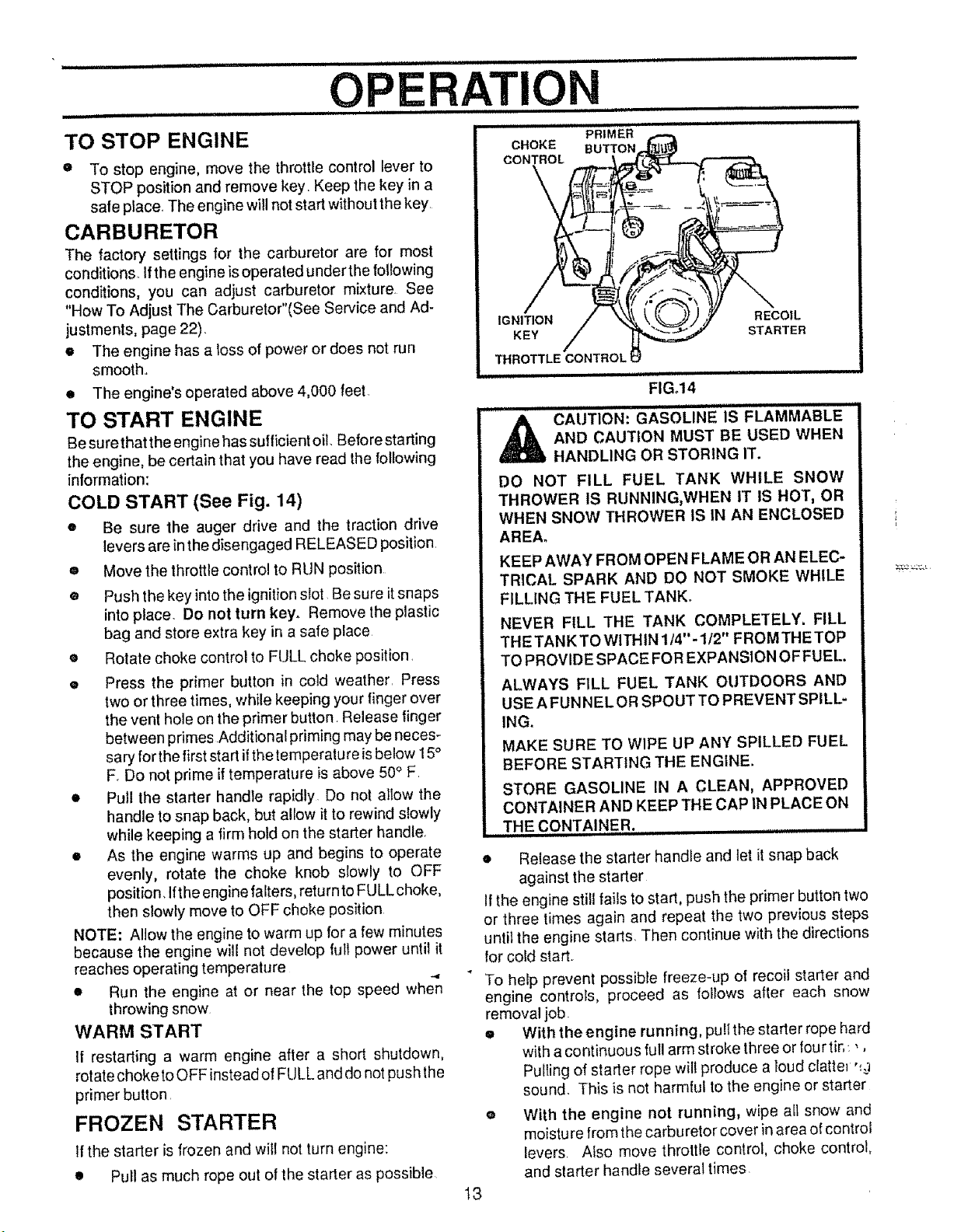
TO STOP ENGINE
o To stop engine, move the throttle control lever to
STOP position and remove key. Keep the key in a
safe place. The engine will not start without the key
CARBURETOR
The factory settings for the carburetor are for most
conditions_ Ifthe engine isoperated underthe foltowing
conditions, you can adjust carburetor mixture. See
"How To Adjust The Carburetor"(See Service and Ad-
justments, page 22).
• The engine has a loss of power or does not run
smooth..
• The engine's operated above 4,000 feet.
TO START ENGINE
Be sure that the engine has sufficient oil. Before starting
the engine, be certain that you have read the following
information:
COLD START (See Fig. 14)
• Be sure the auger drive and the traction drive
levers are inthe disengaged RELEASED positionL
® Move the throttle control to RUN position
® Push the key into the ignition slot Be sure itsnaps
into place. Do not turn key. Remove the plastic
bag and store extra key in a safe place
• Rotate choke control to FULL choke position _
® Press the primer button in cold weather. Press
two or three times, while keeping your finger over
the vent hole on the primer button Release finger
between primes Additional priming may be neces-
sary for the first start ifthe temperature isbelow 15"
F_Do not prime if temperature is above 50° F.
• Pull the starter handle rapidly. Do not allow the
handle to snap back, but allow it to rewind slowly
while keeping a firm hold on the starter handle.
• As the engine warms up and begins to operate
evenly, rotate the choke knob slowly to OFF
position. Ifthe engine falters, return to FULL choke,
then slowly move to OFF choke position
NOTE: Allow the engine to warm up for a few minutes
because the engine will not develop full power until it
reaches operating temperature
• Run the engine at or near the top speed when
throwing snow
WARM START
If restarting a warm engine after a short shutdown,
rotate choke to OFF instead of FULL and do not push the
primer button.
FROZEN STARTER
If the starter is frozen and will not turn engine:
• Pul! as much rope out of the starter as possible
CHOKE
CON_OL
IGNITION RECOIL
KEY STARTER
THROTTLE CONTROL;
i H = =H= i i = H H,H,I=== = HI
i i iii i H,H,=,HH,,, i i ill iiliilil l i
_ CAUTION: GASOLINE IS FLAMMABLE
DO NOT FILL FUEL TANK WHILE SNOW
THROWER IS RUNNING,WHEN IT tS HOT, OR
WHEN SNOW THROWER IS IN AN ENCLOSED
AREA.
KEEP AWAY FROM OPEN FLAME OR AN ELEC-
TRICAL SPARK AND DO NOT SMOKE WHILE
FILLING THE FUEL TANK.
NEVER FILL THE TANK COMPLETELY. FILL
THE TANK TO WITHIN1/4"- I/2" FROMTHETOP
TO PROVIDE SPACE FOR EXPANSION OF FUEL.
ALWAYS FILL FUEL TANK OUTDOORS AND
USE A FUNNEL OR SPOUT TO PREVENT SPILL-
ING.
MAKE SURE TO WIPE UP ANY SPILLED FUEL
BEFORE STARTING THE ENGINE.
STORE GASOLINE IN A CLEAN, APPROVED
CONTAINER AND KEEP THE CAP IN PLACE ON
.....THE CONTAINER. ,,,
• Release the starter handle and let it snap back
against the starter
If the engine still fails to start, push the primer button two
or three times again and repeat the two previous steps
until the engine starts. Then continue with the directions
for cold start.
To help prevent possible freeze-up of recoil starter and
engine controls, proceed as follows after each snow
removal job.
e Withtheenginerunning, pullthestarterropehard
with a continuous full arm stroke three or fourtit,: _,
Pulling of starter rope will produce a loud clatte_ '_
sound. This is not harmful to the engine or starter
o With the engine not running, wipe all snow and
moisture from the carburetor cover in area of control
levers Also move throltle control, choke control,
and starter handle several times.
PRIMER
FIG°14
AND CAUTION MUST BE USED WHEN
HANDLING OR STORING IT.
13
OPE ATION
,ll i llllll i,,i lU ill
,L
CAUTION: NEVER RUN ENGINE
INDOORS OR IN ENCLOSED,
POORLY VENTILATED AREAS.
ENGINE EXHAUST CONTAINS
CARBON MONOXIDE, AN ODORLESS AND
DEADLY GAS. KEEP HANDS, FEET, HAIR AND
LOOSE CLOTHING AWAY FROM ANY MOVING
PARTS ON ENGINE AND SNOW THROWER.
WARNING: TEMPERATURE OF MUFFLER AND
NEARBY AREAS MAY EXCEED 150 ° FoAVOID
THESE AREAS.
DO NOT ALLOW CHILDREN OR YOUNG TEEN-
AGERS TO OPERATE OR BE NEAR SNOW
THROWER WHILE IT IS OPERATING.
i i i u i i iii i iiiiiiiiiiiiiiiiiiiiiiiiiiii
CAUTION: DO NOT ATTEMPT TO RE-
D
O ngravel or crushed rock surfaces, set the skids at
I-1/4" below the scraper bar (see To Adjust Skid
Height paragraph on page 18)_Stones and gravel
must not be picked up and thrown by the machine..
• After the snow throwing job has been completed,
allow the engine to idle for a few minutes, which will
melt snow and accumulated ice off the engine
• Clean the snow thrower thoroughly after each use.
• Remove ice and snow accumulation and all debris
from the entire snow thrower, and flush with water
(if possibte) to remove all sait or other chemicals
Wipe snow thrower dry
,_ MOVE ANY ITEM THAT MAY BECOME
LODGED IN AUGER WITHOUT TAKING
THE FOLLOWING PRECAUTIONS:
• RELEASE AUGER DRIVE AND TRACTION
DRIVE LEVERS.
• MOVE THROTTLE LEVER TO STOP POSI-
TION,
® REMOVE (DO NOTTURN) IGNITION KEY.
• DISCONNECT SPARK PLUG WIRE.
e DO NOT PLACE YOUR HANDS IN THE
AUGER OR DISCHARGE CHUTE. USE A
PRY BAR.
SNOW THROWING TIPS
It For maximum snow thrower efiiciency in removing
snow, adjust ground speed, NEVER the throttle
Go slower in deep, freezing, or wet snow If the
track slips, reduce forward speed The engine is
designed to deliver maximum performance at full
throttle and should be run at this power setting at all
times_.
® Most efficient snowthrowing is accomplished when
the snow is removed immediately after it falls.
• For complete snow removal, slightly overlap each
path previously taken.
o The snow should be discharged down wind when-
ever possible.
• For normal usage, set the skids so that the scraper
bar is 1/8" above the skids For extremely hard-
packed snow surfaces, adjust theskids upward so
that the scraper bar touches the ground
14
 Loading...