

Craftsman 536886350 Owner’s Manual
CRRFTSMRW
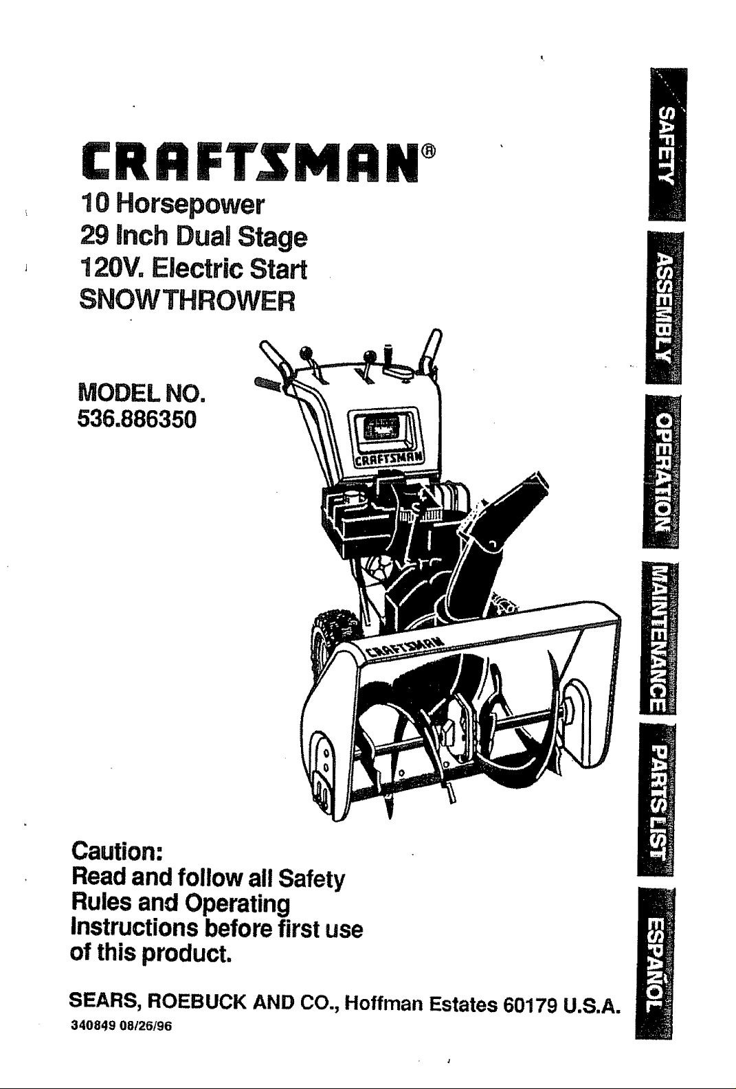
10 Horsepower
29 Inch Dual Stage
120V. Electric Start
SNOWTHROWER
MODEL NO,
536.886350
Caution:
Read and follow all Safety
Rules and Operating
Instructions before first use
of this product,
SEARS, ROEBUCK AND CO., Hoffman Estates 60179 U.S.A.
340849 08/26/96
Table of Contents 2
Warranty 2
Safety Rules 2-4
Contents of Shipping Carton 4-5
Assembly 5-9
Operation !0-14
Maintenance 15-17
Service and Adjustments 18-23
Storage 24
Troubleshooting 25
Snow Thrower Repair Parts 26-38
Engine Repair Parts 39-42
Spanish(EspaSol) 43-69
Parts Ordering/Service Back Cover
LIMITED TWO-YEAR WARRANTY ON CRAFTSMAN SNOW THROWER
For two years from the date of purchase, when this Craltsman Snow Thrower is main-
tained, lubricated, and tuned up according to the operating and maintenance instruc-
tions in the owner's manual, Sears will repair, free of charge, any defect in material or
workmanship.
if this Craftsman Snow Thrower is used for commercial or rental purposes, this war-
ranty applies for only 90 days from the date of purchase.
This warranty does not cover the following:
- Items which become worn during normal use, such as spark plugs, drive belts and
shear pins.
• Repairs necessary because of operator abuse or negligence, including bent crank
shafts and the failure to maintain the equipment according to the instructions con_
rained inthe owner's manual.
WARRANTY SERVICE IS AVAILABLE BY RETURNING THE CRAFTSMAN SNOW
THROWER TO THE NEAREST SEARS SERVICE CENTER/DEPARTMENT IN THE
UNITED STATES, THIS WARRANTY APPLIES ONLY WHILE THIS PRODUCT IS IN
USE IN THE UNITED STATES,
This warranty gives you specific legal rights, and you may also have other rights which
may vary from state to staten
Sears, Roebuck and Co., D817WA, Hoffman Estates, IL 60179
Look for this symbol to point out Important safety precautions, It means---
ATTENTION!!! Become alert!!! Your safety is involved.
CAUTION: Always disconnect spark
plug wire and place wire where it cannot
contact spark plug to prevent accidental
starting when setting-up, transporting,
adjusting or making repairs.
IMPORTANT: Safety standards require
operator presence controls to minimize the
risk of injury. Your snow thrower is
equipped with such controls° Do not attempt
to defeat the function of the operator
presence control under any circumstances.
TRAINING
1. Read the operator's manual carefully.
Be thoroughly familiar with the controls
and the proper use of the snow thrower.
Know how to stop the snow thrower and
disengage the controls quickly.
2. Never allow children to operate the
snow thrower and keep them away
while it is operating. Never allow adults
to operate the snow thrower without
proper instruction. Do not carry passen-
gers.
3_
Keep the area of operation clear of all
persons, particularly small children and
pets.
,
Exercise caution to avoid slipping or
falling, especially when operating in
reverse.
PREPARATION
1. Thoroughly inspect the area where the
snow thrower is to be used and remove
all doormats, sleds, boards, wires and
other foreign objects.
Disengage all clutches before starting
the engine (motor).
3. Do not operate the snow thrower
2
without wearing adequate winter outer
garments. Wear footwear that will
improve footing on slippery surfaces.
4. Handle fuel with care; it is highly
flammable. 6,
(a) Use an approved fuel container.
(b) Never remove fuel tank cap or add
fuel to a running engine or hot
engine.
(c) Fill fuel tank outdoors with extreme 7.
care. Never flit fuel tank indoors.
(d) Replace fuel tank cap securely and
wipe up spilled fuel
(e) Never store fuel or snow thrower 8.
with fuel in the tank inside of a
building where fumes may reach
an open flame or spark,
(f) Check fuel supply before each use,
allowing space for expansion as 9.
the heat of the engine (motor) and/
or sun can cause fuel to expand.
S. Use extension cords and receptacles
as specified by the manufacturer for all 10.
snow throwers with electric drive
motors or electric starting motors.
6. Adjust the snow thrower height to clear
gravel or crushed rock surfaces.
7. Never attempt to make any adjustments
while the engine (motor) is running 11,
(except when specifically recom-
mended by the manufacturer).
8. Let engine (motor) and snow thrower
adjust to outdoor temperatures before 12.
starting to clear snow,
9. Always wear safety glasses or eye 13.
shields during operation or while
performing an adjustment or repair to
protect eyes from foreign objects that
may be thrown from the snow thrower.
OPERATION 14.
1. Do not operate this machine if you are
taking drugs orother medication which 15.
can cause drowsiness or affect your
ability to operate this machine.
2. Do not use this machine if you are
mentally or physically unable to operate 16.
this machine safely_
3. Do not put hands or feet near or under
rotating parts. Keep clear of the 17.
discharge opening at all times.
4. Exercise extreme caution when operat-
ing on or crossing gravel drives, walks, 18.
or roads. Stay alert for hidden hazards
or traffic.
5o After striking a foreign object, stop the
engine (motor), remove the wire from
the spark plug, disconnect the cord on
electric motors, thoroughly inspect the
snow thrower for any damage, and
repair the damage before restarting and
operating the snow thrower.
tf the snow thrower should start to
vibrate abnorrdally, stop the (motor)
check immediately for the cause_
Vibration is generally a warning of
trouble.
Stop the engine (motor) whenever you
leave the operating position, before
unclogging the auger/impeller housing or
discharge guide, and when making any
repairs, adjustments, or inspections,
When cleaning, repairing, or inspecting,
make certain the auger/impeller and all
moving parts have stopped. Disconnect
the spark plug wire and keep the wire
away from the plug to prevent accidental
starting.
Take all possible precautions when
leaving the snow thrower unattended.
Disengage the. auger/impeller, stop
engine, and remove key.
Do not run the engine indoors, except
when starting the engine and for
transporting the snow thrower in or out
of the building. Open the outside doors;
exhaust fumes are dangerous (contain-
ing CARBON MONOXIDE, an ODOR-
LESS and DEADLY GAS).
Do not clear snow across the face of
slopes. Exercise caution when changing
direction on slopes. Do not attempt to
cle.ar steep slopes_
Never operate the snow thrower without
proper guards, plates or other safety
protective devices in place.
Never operate the snow thrower near
glass enclosures, automobiles, window
wells, drop-offs, and the like without
proper adjustment of the snow discharge
angle. Keep children and pets away,
Do not overload the machine capacity by
attempting to clear snow at too fast a
rate,
Never operate the snow thrower at high
transport speeds on slippery surfaces.
Look behind and use care when
backing.
N_ver direct discharge at bystanders or
allow anyone in front of the snow
thrower.
Disengage power to the auger/impeller
when snow thrower is transportedor not
In use.
Use only attachments and accessories
approved by the manufacturer of the
snow thrower (such as tire chains,
electric start kits, etc)_
19o
Neveroperatethesnowthrower
withoutgoodvisibilityorlighLAlways
besureofyourfooting,andkeepa
firm holdonthehandles_Walk;never
run.
MAINTENANCE AND STORAGE
1. Check shear bolts and other bolts
frequently for proper tightness to be
sure the snow thrower is in safe ,
working condition.
2. Never store the snow thrower with fuel
in the fuel tank inside a building where
ignition sources are present such as
hot water and space heaters, clothes
dryers, and the like. Allow the engine
to cool before storing in any enclosure.
3. Always refer to operator's manual
instructions for important details if the
snow thrower is to be stored for an
extended period.
4. Maintain or replace safety and
instruction labels, as necessary.
5. Run the snow thrower a few minutes
after throwing snow to prevent freeze-
up of the augedimpeller.
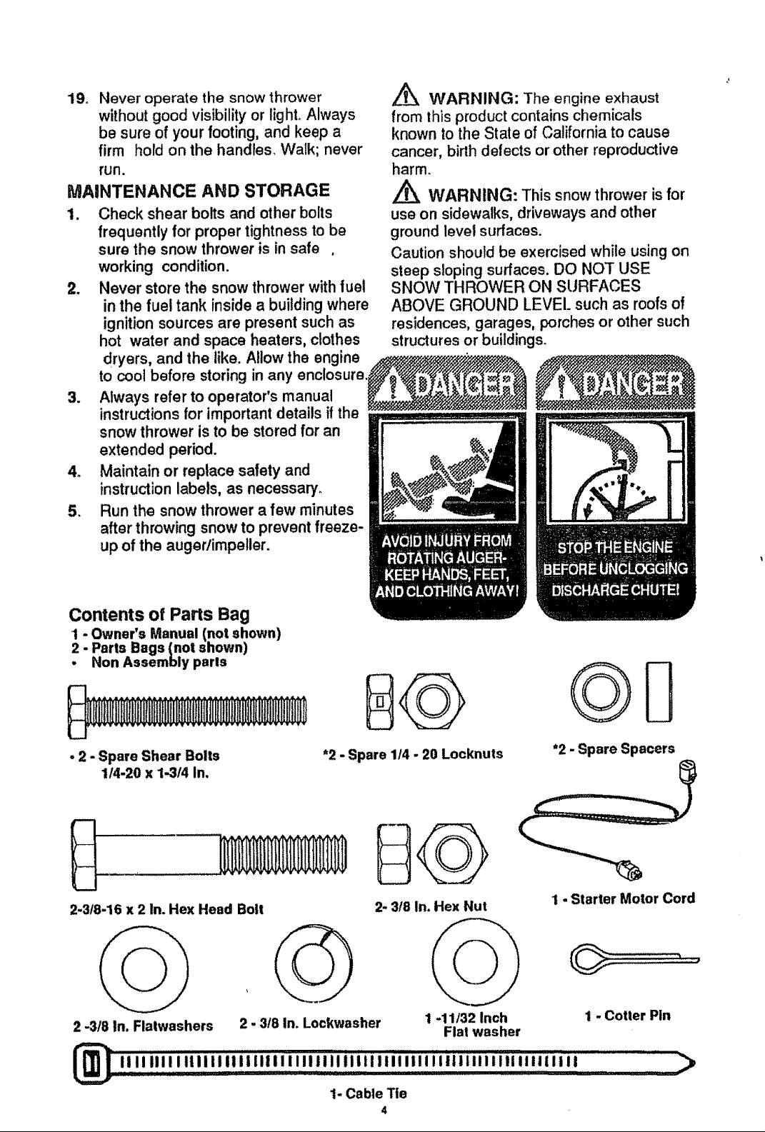
,_ WARNING: The engine exhaust
from this product contains chemicals
known to the State of California to cause
cancer, birth defects or other reproductive
harm.
Z_ WARNING: This snow thrower is for
use on sidewalks, driveways and other
ground level surfaces.
Caution should be exercised while using on
steep sloping surfaces. DO NOT USE
SNOW THROWER ON SURFACES
ABOVE GROUND LEVEl. such as roofs of
residences, garages, porches or other such
structures or buildings.
Contents of Parts Bag
Parts Bags (not shown)
- Owner's Manual (not shown)
Non Assembly paris
• 2 - Spare Shear Bolts
114-20 x 1-314 In.
2.3t8-16 x 2 In. Hex Head Bolt
2 .318 In, Flatwashers
2 - 3/8 In. Lockwasher
*2 - Spare 1/4 - 20 Locknuts
2- 3/8 In. Hex Nut
1 -11/32 Inch
Flat washer
"2 - Spare Spacers
I - Starter Motor Cord
1 - Cotter Pin
,,,,,,,ii,,,,,,,,,,,,.,,,,,,,,,,,,,,,,,,,,,,,,,,,,,,,,,,,,,,,,, >
1- Cable Tie
4
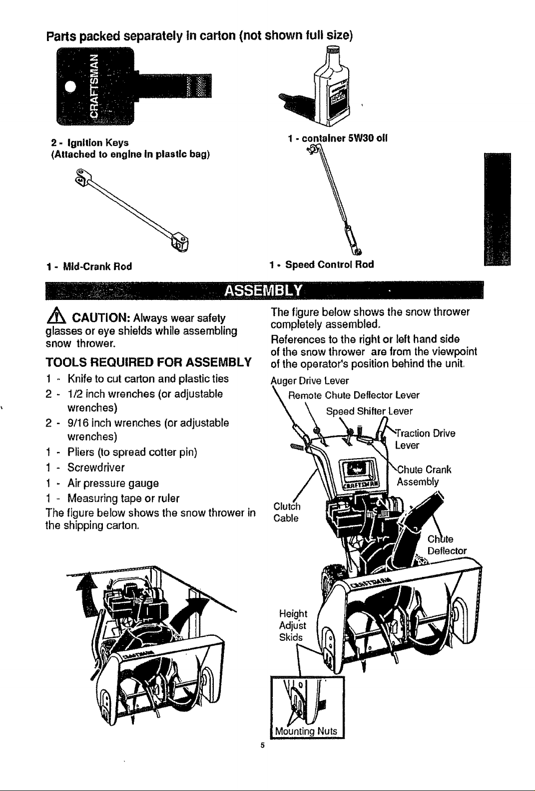
Parts packed separately In carton (not shown full size)
2- Ignlllon Keys
(Attached to engine In plastic bag)
1 - Mid-Crank Rod
/_ CAUTION: Always wear safety
glasses or eye shields while assembling
snow thrower,
TOOLS REQUIRED FOR ASSEMBLY
1 - Knifeto cutcarton and plasticties
2 - 1/2 inch wrenches (or adjustable
wrenches)
2 - 9/16 inch wrenches (or adjustable
wrenches)
1 - Pliers (to spread cotter pin)
I- Screwdriver
1 - Air pressure gauge
1 - Measuring tape or ruler
The figure below shows the snow throwerin
the shippingcarton,
1 - container 5W30 oll
1 - Speed Control Rod
The figure below shows the snow thrower
completely assembled,
References to the right or left hand side
of the snow thrower are from the viewpoint
of the operator's position behind the unit.
Auger Drive Lever
Remote Chute Deflector Lever
_eedShifter Lever
Drive
Lever
Crank
Assembly
C
Cable
Deflector
Height
Adjust
Skids
5
HOW TO SET UP YOUR SNOW
THROWER
• Locate and remove container of 5W30 oil
and parts bag found in parts box.
. Remove top palletfrom carton.
• Cut and discardthe plasticties securing
the mid-chute rod and speed control rod
to the pallet, place them aside. Discard
pallet.
o Cut all fourcorners of the carton from top
to bottomand lay the panels flat.
• Cut the bands holdingthe snowthrower
to the lower pallet°
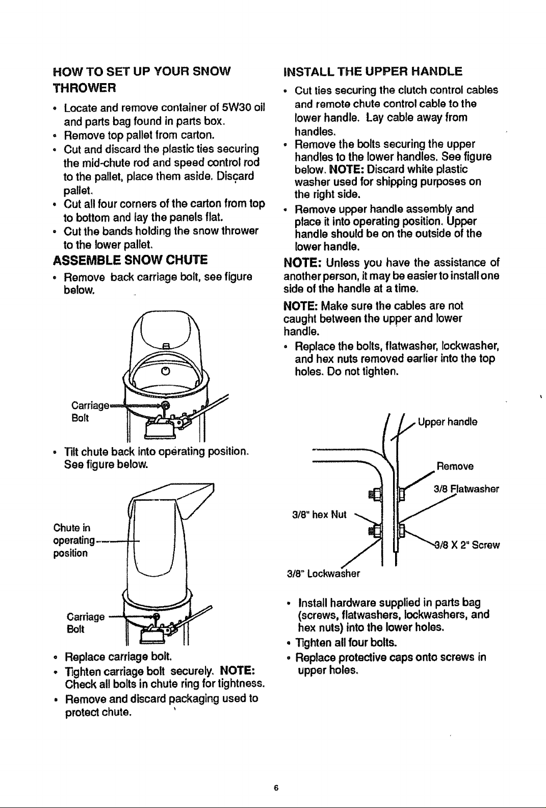
ASSEMBLE SNOW CHUTE
• Remove back carriage bolt, see figure
below.
iNSTALL THE UPPER HANDLE
• Cut ties securingthe clutchcontrol cables
and remote chute controlcable to the
lower handle. Lay cable away from
handles.
• Remove the bolts securing the upper
handles to the lower handles, See figure
below. NOTE: Discard white plastic
washer used for shippingpurposes on
the rightside.
. Remove upper handle assembly and
place it intooperating position.Upper
handle should be on the outside of the
lower handle.
NOTE: Unless you have the assistance of
another person, itmay be easier to installone
side of the handle at a time.
NOTE: Make sure lhe cables are not
caught between the upper and lower
handle.
• Replace the bolts, flatwasher, Iockwasher,
and hex nuts removed earlier into the top
holes. Do nottighten.
Bolt
. Tilt chute back into operating position.
See figure below.
Chute in
operating---.--.
position
Carriagew _...,.,_ . _
Bolt
o
Replace carriage bolt.
O
lighten carriage bolt securely. NOTE:
Check all boltsin chute ring for tightness,
Remove and discard packaging used to
protect chute.
i lll ii,
Remove
318 Flatwasher
3/8"hexNut .-_
X 2"Screw
3t8" Lockwasher
L
• Install hardware supplied in partsbag
(screws, flatwashers, Iockwashers, and
hex nuts) intothe lower holes.
° Tighten all four bolts.
° Replace protective capsonto screws in
upper holes.
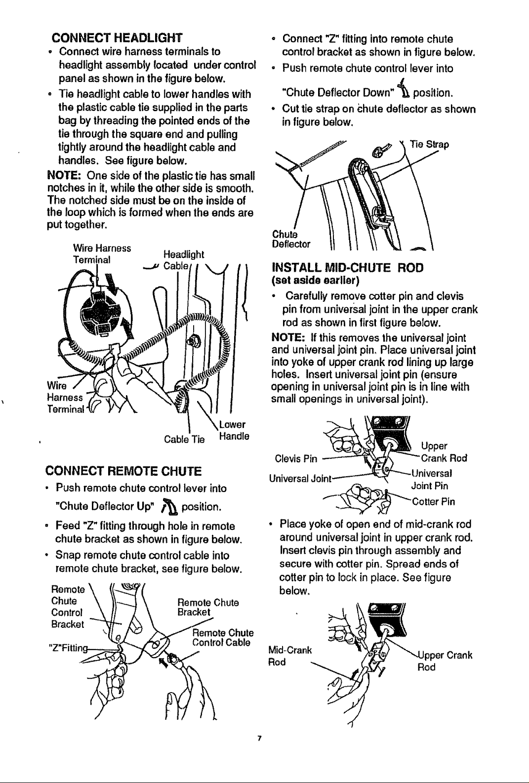
CONNECT HEADLIGHT
• Connectwireharnessterminalsto
headlightassemblylocatedundercontrol
panelasshowninthefigurebelow.
• Tieheadlightcableto lowerhandleswith
theplasticcabletiesuppliedintheparts
bagbythreadingthepointedends ofthe
tie through the square end and pulling
tightlyaround the headlight cable and
handles. See figure below.
NOTE: One side of the plastictie has small
notches in it, while the other side issmooth.
The notched side must be on the insideof
the loop which isformed when the ends are
put together.
Wire Harness
Terminat Headlight
Wire
Harness
Termir
CONNECT REMOTE CHUTE
• Push remote chute control lever into
"Chute Deflector
- Feed "Z" fitting through hole in remote
chute bracket as shown in figure below.
• Snap remote chute control cable into
remote chute bracket, see figure below.
Remote
Chute Remote Chute
Control Bracket
Bracket
J Cable
Cable Tie
Up" /'_ position.
Control Cable
Lower
Handle
Chute
o Connect "Z" fittinginto remote chute
control bracket as shown in figure below.
• Push remote chute contro! lever into
"Chute Deflector Down" '=_ position.
° Cut tie strap on chute deflector as shown
infigure below.
Chute
Deflector
INSTALL MID-CHUTE ROD
(set aside earlier)
• Carefully remove cotter pin and clevis
pin from universaljoint in the upper crank
rod as shown in firstfigure below.
NOTE; If this removes the universal joint
and universaljoint pin, Place universal joint
intoyoke of upper crank rod liningup large
holes. Insertuniversal joint pin (ensure
opening in universal joint pin is inline with
small openings in universaljoint),
Upper
Clevis Pin Rod
UniversalJoint
.,.__Joint Pin
CotterPin
° Place yoke of open end of mid-crank rod
around universal joint in upper crank rod.
Insertclevis pin through assembly and
secure withcotter pin.Spread ends of
cotter pin to lock inplace. See figure
below.
Mid-Crank pper Crank
Rod Rod
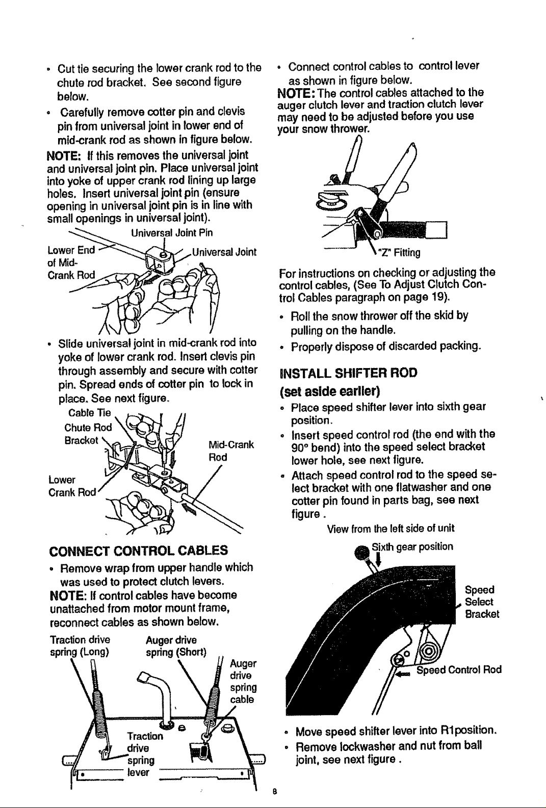
Cut tie securing the rower crank rodto the
chute rod bracket. See second figure
below.
, Carefully remove cotter pin and clevis
pin from universal jointin lower end of
mid-crank rod as shown in figure below.
NOTE: tfthis removes the universaljoint
and universal joint pin. Place universaljoint
intoyoke of upper crank rod lining up large
holes, Insert universal joint pin (ensure
opening in universal joint pin isin linewith
small openings in universaljoint).
"_--..._ UniversalJointPin
LowerEn__"-_.._ _..ttniversal Joint
/
Slide universal, ofntin mid-crank rod into
yoke of lower crank rod. Insert clevis pin
through assembly and secure with cotter
pin. Spread ends of cotter pin to lockin
place. See next figure.
CableTie _._._ ,
ChuteRod"k_-_
_/// Mid-Crank
Rod
Lowo 7"
Crank Rod" @-_
• Connect controlcabtes to control lever
as shown in figure below.
NOTE: The control cables attached to the
auger clutch lever and traction clutch lever
may need to be adjusted before you use
your snow thrower.
Z" Fitting
For instructionson checkingor adjusting the
control cables, (See To AdjustClutch Con-
trol Cables paragraph on page 19).
o Roll the snow thrower off the skidby
pulling on the handle.
• Properly dispose of discarded packing.
INSTALL SHIFTER ROD
(set aside earlier)
° Place speed shifter lever intosixthgear
position.
• Insert speed control rod (the end with the
90° bend) into the speed select bracket
lower hole, see next figure.
- Attach speed control rod to the speed se-
lect bracket with one flatwasher and one
cotter pin foundin parts bag, see next
figure°
Viewfrom theleftsideof unit
CONNECT CONTROL CABLES
, Remove wrap from upper handle which
was used to protect clutchlevers,
NOTE: If control cables have become
unattached from motormount frame,
reconnect cables as shown below.
Traction drive Augerdrive
(Long) spring (Short)
Auger
ddve
spdng
cable
pdng
_o lever
Speed Control Rod
o
Move speed shifter lever into Rlposition.
°
Remove lockwasher and nut from ball
joint, see next figure,
Speed
Select
Bracket
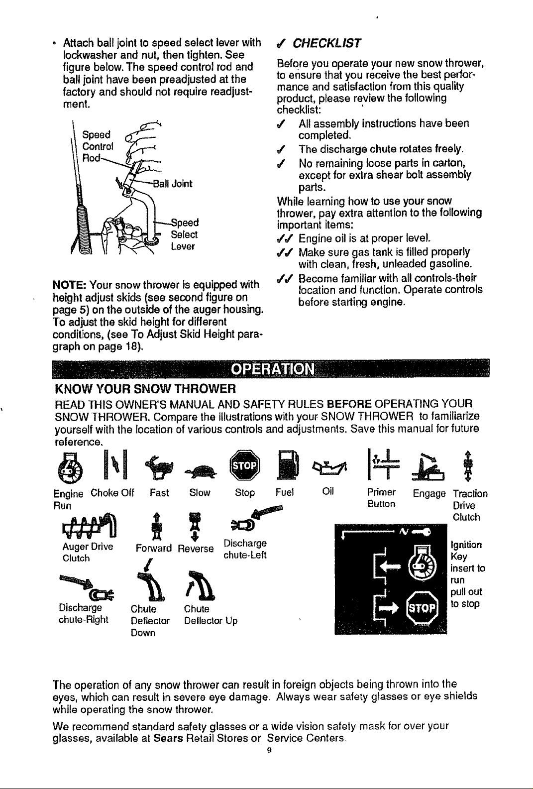
Attach ball joint to speed select lever with
Iockwasher and nut, then tighten. See
figure below. The speed control rod and
ball joint have been preadjusted at the
factory and should not require readjust-
ment.
Speed
Control
Joint
_eed
Select
Lever
NOTE: Your snow thrower is equipped with
height adjust skids (see second figure on
page 5) on the outside of the auger housing.
To adjust the skid height for different
conditions, (see To AdjustSkid Height para-
graph on page t8).
J CHECKLIST
Before you operate your new snow thrower,
to ensure that you receive the best perfor-
mance and satisfaction from this quality
product, please review the following
checklist:
All assembly instructions have been
completed.
#' The discharge chute rotates freety.
4' No remaining loose parts in carton,
except for extra shear bolt assembly
parts.
While learning how to use your snow
thrower, pay extra attention to the following
important items:
J',# Engine oil is at proper level.
#'J Make sure gas tank is filled properly
with clean, fresh, unleaded gasoline.
_'J Become familiar with all controls-their
location and function. Operate controls
before starting engine.
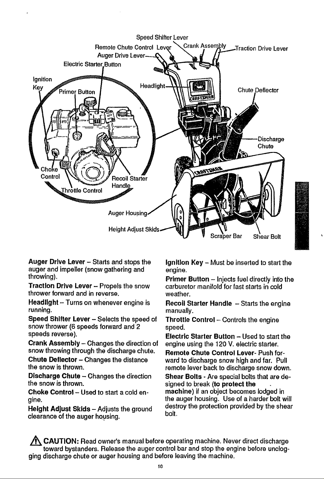
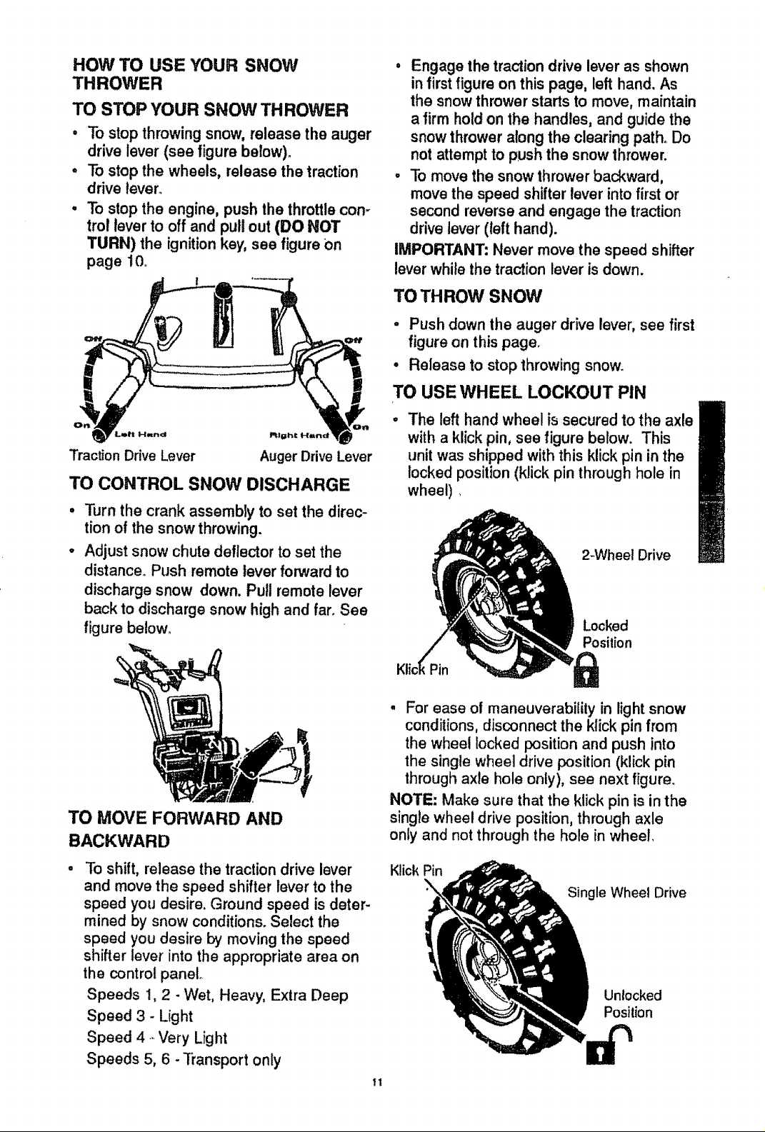
KNOW YOUR SNOW THROWER
READ THIS OWNER'S MANUAL AND SAFETY RULES BEFORE OPERATING YOUR
SNOW THROWER, Compare the illustrationswithyour SNOW THROWER to familiarize
yourself with the location ofvarious controlsand adjustments, Save this manual for future
reference_
Engine Choke Otf
Run
Auger Drive
Clutch
Fast Slow
Forward Reverse Discharge
/
Discharge Chute Chute
chute-Right Detlector Detlector Up
Down
Stop Fuel
chute-Left
Oil Primer Engage Traction
Button Drive
Clutch
Ignition
Key
insertto
run
pullout
to stop
The operation of any snow thrower can result in foreign objects being thrown into the
eyes, which can result in severe eye damage. Always wear safety glasses or eye shietds
while operating the snow thrower_
We recommend standard safety glasses or a wide vision safety mask for over your
glasses, available at Sears Retail Stores or Sewice Centers_
9
Remole Chute Control Lever
Auger Drive
ElectricStartel Button
Speed Shifter Lever
\
Drive Lever
ignition
Control
_ttteControl
Headl
Recoil Starter
Auger Housing
Height Adjust
Chute Deflector
e
Chute
Bolt
Auger Drive Lever - Starts and stops the
auger and impeller (snow gathering and
throwing),
Traction Drive Lever - Propels the snow
thrower forward and in reverse,
Headlight - Turns on whe_neverengine is
running.
Speed Shifter Lever - Selects the speed of
snow thrower (6 speeds forward and 2
speeds reverse).
Crank Assembly- Changes the directionol
snow throwingthrough the discharge chute.
Chute Deflector - Changes the distance
the snow isthrown,
Discharge Chute - Changes the direction
the snow isthrown.
Choke Control - Used to start a cold en-
gine.
Height Adjust Skids - Adjusts the ground
clearance of the auger housing.
Ignition Key - Must be inserted to start the
engine.
Primer Button - Injects fuel directly into the
carburetor manifold for fast starts in cold
weather.
Recoil Starter Handle - Starts the engine
manually.
Throttle Control - Controls the engine
speed.
Electric Starter Button - Used to start the
engine using the 120 V, electric starter.
Remote Chute Control Lever- Push for-
ward to discharge snow high and far. Pull
remote lever back to discharge snow down°
Shear Bolls - Are special bolts that are de-
signed to break (to protect the
machine) if an object becomes lodged in
the auger housing. Use of a harder bolt will
destroy the protection provided by the shear
bolt.
CAUTION: Read owner's manual before operating machine, Never direct discharge
toward bystanders, Release the auger control bar and stop the engine betore unclog-
ging discharge chute or auger housing and before leaving the machine.
10
HOW TO USE YOUR SNOW
THROWER
TO STOP YOUR SNOW THROWER
• To stop throwing snow, release the auger
drive lever (see figure below).
. To stop the wheels, release the traction
drive lever.
° Tostop the engine, push the throttlecon-
trol lever to off and pull out (DO NOT
TURN) the ignitionkey, see figure on
page 10_
Traction Drive Lever
TO CONTROL SNOW DISCHARGE
Turn the crank assembly to set the direc-
tion of the snow throwing.
Adjust snow chute deflector to set the
distance. Push remote lever forward to
discharge snow down. Pull remote lever
back to discharge snow high and far. See
figure be!ow_
Auger Drive Lever
• Engage the traction drive lever as shown
in first figure on this page, left hand. As
the snow thrower starts to move, maintain
a firm hold on the handles, and guide the
snow thrower along the clearing path. Do
not attempt to push the snow thrower.
• To move the snow thrower backward,
move the speed shifter lever into first or
second reverse and engage the traction
drive lever (left hand).
IMPORTANT: Never move the speed shifter
lever while the traction lever is down.
TO THROW SNOW
• Push down the auger drive lever, see first
figure on this page.
• Release to stop throwing snow.
TO USE WHEEL LOCKOUT PIN
The left hand wheel is secured to the axle
with a klick pin, see figure below. This
unit was shipped with this klick pin in the
locked position (klick pin through hole in
wheel)
2-Wheet Drive
Locked
Position
TO MOVE FORWARD AND
BACKWARD
To shift, release the traction drive lever
and move the speed shifter lever to the
speed you desire. Ground speed is deter-
mined by snow conditions. Select the
speed you desire by moving the speed
shifter lever into the appropriate area on
the control panel
Speeds !, 2 - Wet, Heavy, Extra Deep
Speed 3 - Light
Speed 4- Very Light
Speeds 5, 6 -"ffansport only
• For ease of maneuverability in light snow
conditions, disconnect the klick pin from
the wheel locked position and push into
the single wheel drive position (klick pin
through axle hole only), see next figure.
NOTE: Make sure that the klick pin is in the
single wheel drive position, through axle
only and not through the hole in wheel,
Klick Pin
Single Wheel Drive
Unlocked
Position
11
BEFORE STARTING THE ENGINE
- if the snow thrower must be moved with-
out the aid of the engine, it is easier to pull
the snow thrower by the handles rather
than pushing°
, Before you service or start the engine, fa-
miliarize yourself with the snow thrower.
Be sure you understand the function and
location of all controls.
NOTE: Check tension of clutch cables be-
fore starting the engine (See To AdjustThe
Control Cables paragraph on page !g).
• Be sure that allfasteners are tight.
° Make sure the height adjust skidsare
properly adjusted (See To Adjust Skid
Height paragraph on page 18).
, Check tire pressure (14 to 17 pounds).
See side of tire for maximum inflation.Do
not exceed listed maximum pressure.
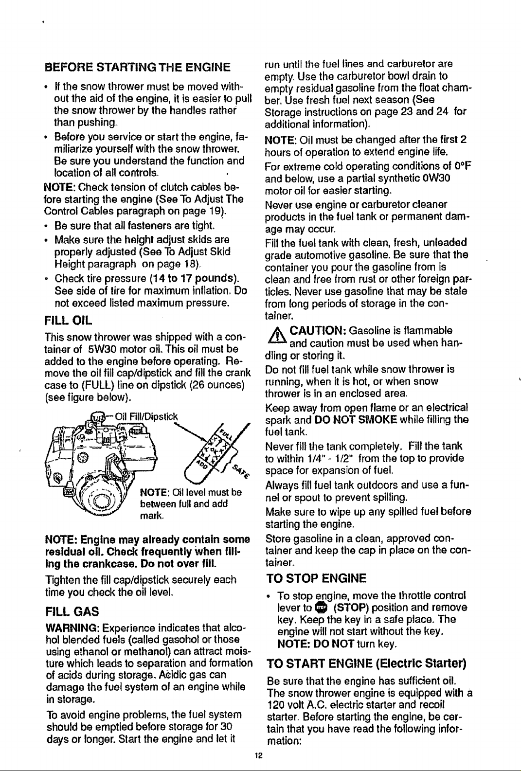
FILL OIL
This snow thrower was shipped with a con-
tainer of 5W30 motor oiloThis oil must be
added to the engine before operating. Re-
move the oil fill cap/dipstick and fill the crank
case to (FULL) line on dipstick (26 ounces)
(see figure below).
Fill/Dipstick
NOTE: Oil level must be
between full and add
mark.
NOTE: Engine may already contain some
residual oil Check frequently When fill-
Ing the crankcase. Do not over fill.
Tighten the fill cap/dipstick securely each
time you check the oil level,
FILL GAS
WARNING: Experience indicates that alco-
hol blended fuels (called gasohot or those
usingethanol or methanol) can attract mois-
ture which leads to separation and formation
of acids during storage. A_idicgas can
damage the fue! system o! an engine while
in storage.
To avoidengine problems,the fuel system
should be emptied before storage for 30
days or longer. Start the engine and let it
run until the fuel lines and carburetor are
empty Use the carburetor bow! drain to
empty residual gasoline from the float cham-
ber. Use fresh fuel next season (See
Storage instructions on page 23 and 24 for
additional in!ormation).
NOTE: Oil must be changed after the first 2
hours of operation to extend engine life.
For extreme cold operating conditions of 0°F
and below, use a partial synthetic 0W30
motor oil for easier starting°
Never use engine or carburetor cleaner
products in the fuel tank or permanent dam-
age may occur_
Fill the fuel tank with clean, fresh, unleaded
grade automotive gasoline. Be sure that the
container you pour the gasoline from is
clean and free from rust or other foreign par-
ticles. Never use gasoline that may be state
from long periods of storage in the con-
tainer.
/_ CAUTION: Gasoline is flammable
and caution must be used when han-
dling or storing it.
Do not fil! fuel tank while snow thrower is
running, when it is hot, or when snow
thrower is in an enclosed area.
Keep away from open flame or an electrical
spark and DO NOT SMOKE while filling the
fuel tank.
Never fill the tank completely. Fill the tank
to within 1/4" - 1/2" from the top to provide
space for expansion of fuel.
Always fill fue! tank outdoors and use a fun-
nel or spout to prevent spilling.
Make sure to wipe up any spilled fuel before
starting the engine.
Store gasoline in a clean, approved con-
tainer and keep the cap in place on the con-
tainen
TO STOP ENGINE
To stop engine, move the throttle control
lever to _ (STOP) positton and remove
key. Keep the key in a safe place. The
engine will not start without the key.
NOTE: DO NOT turn key.
TO START ENGINE (Electric Starter)
Be sure that the engine has sufficient oil.
The snow thrower engine is equipped with a
120 volt A.Co electric starter and recoil
starter. Before starting the engine, be cer-
tain that you have read the following infor-
mation:
12
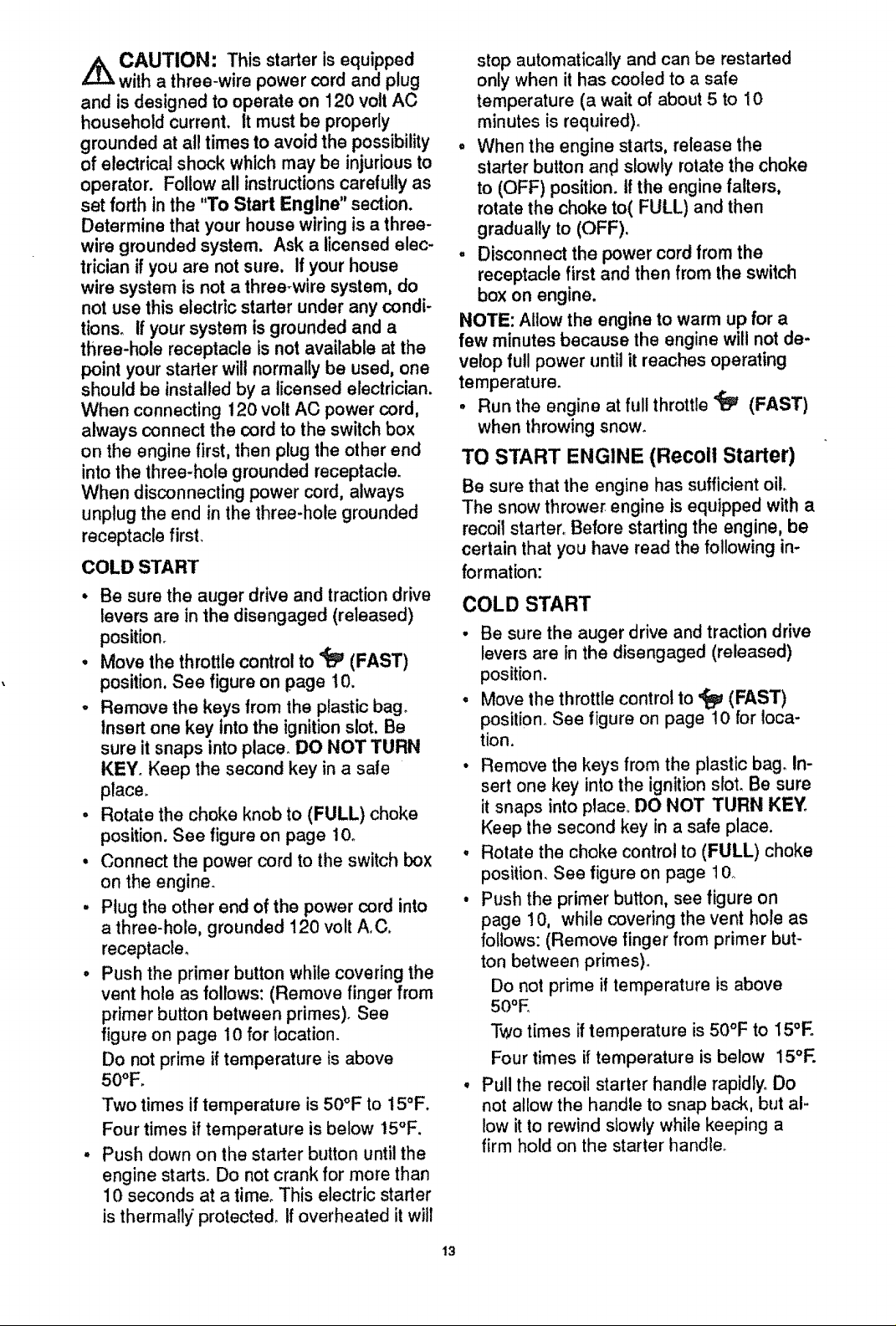
,_k CAUTION: This starter isequipped
Z.L%
with a three-wire power cord and plug
and is designed to operate on 120 volt AC
household current. It must be properly
grounded at a!l times to avoid the possibility
of electricalshock which may be injuriousto
operator. Follow all instructionscarefullyas
set forth in the "To Start Engine" section.
Determine that your house wiring is a three-
wire grounded system. Ask a licensed elec-
trician if you are notsure, If your house
wire system is not a three-wire system, do
not use this electricstarter under any condi-
tions. If your system isgrounded and a
three-hole receptacle is not available atthe
point your starter will normallybe used, one
should be installed by a licensedelectrician.
When connecting 120 volt AC power cord,
always connect the cordto the switchbox
on the engine first,then plug the other end
intothe three-hole grounded receptacle.
When disconnectingpower cord, always
unplugthe end in the three-hole grounded
receptacle first.
COLD START
• Be sure the auger drive and traction drive
levers are in the disengaged (released)
position_
• Move the throttle control to _ (FAST)
position, See figure on page 10.
o Remove the keys from the plastic bag°
Insert one key into the ignition slot. Be
sure it snaps into place_ DO NOT TURN
KEY. Keep the second key in a safe
place.
• Rotate the choke knob to (FULL) choke
position. See figure on page 10o
• Connect the power cord to the switch box
on the engine.
• Plug the other end of the power cord into
a three-hole, grounded 120 volt A.C.
receptacle_
° Push the primer button while covering the
vent hole as follows: (Remove finger from
primer button between primes). See
figure on page 10 for location.
Do not prime if temperature is above
50°F.
Two times if temperature is 50°F to 15°F.
Four times if temperature is below 15°F.
Push down on the starter button until the
engine starts. Do not crank for more than
10 seconds at a time° This electric starter
is thermall_i protected, tf overheated it will
stop automatically and can be restarted
only when it has cooled to a safe
temperature (a wait of about 5 to 10
minutes is required).
• When the engine starts, release the
starter button an€ slowly rotate the choke
to (OFF) position, tf the engine falters,
rotate the choke to(FULL) and then
gradually to (OFF).
, Disconnect the power cord from the
receptacle first and then from the switch
box on engine.
NOTE: Allow the engine to warm up for a
few minutes because the engine will not de-
velop full power until it reaches operating
temperature.
• Run the engine at full throttle _ (FAST)
when throwing snow_
TO START ENGINE (Recolt Starter)
Be sure that the engine has sufficient oil.
The snow thrower engine is equipped with a
recoil starter. Before starting the engine, be
certain that you have read the following in-
formation:
COLD START
• Be sure the auger drive and traction drive
levers are in the disengaged (released)
position.
• Move the throttle control to '_ (FAST)
position. See figure on page 10 for loca-
tion.
• Remove the keys from the plastic bag. In-
sert one key into the ignition slot. Be sure
it snaps into place. DO NOT TURN KEY°
Keep the second key in a safe place.
, Rotate the choke control to (FULL) choke
position. See figure on page t 0"
• Push the primer button, see figure on
page 10, while covering the vent hole as
follows: (Remove finger from primer but-
ton between primes).
Do not prime if temperature is above
50oE
Two times if temperature is 50°F to 15°E
Four times if temperature is below 15°F.
° Pull the recoil starter handle rapidly. Do
not allow the handle to snap back, but al-
low it to rewind slowly while keeping a
firm hold on the starter handle.
13
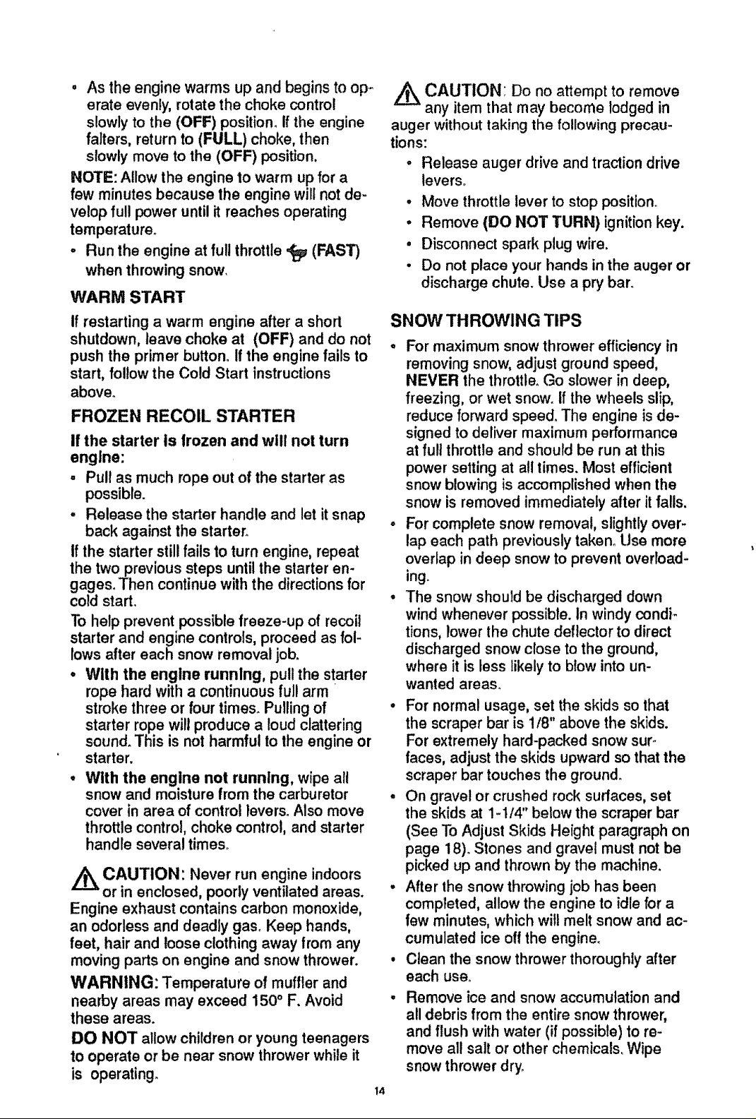
• As the engine warms up and begins to op-
erate evenly, rotate the choke control
slowly to the (OFF) position. If the engine
falters, return to (FULL) choke, then
slowly move to the (OFF) position.
NOTE: Allow the engine to warm up for a
few minutes because the engine will not de-
velop full power until it reaches operating
temperature_
- Run the engine at full throttle ,tEp (FAST)
when throwing snow.
WARM START
If restarting a warm engine after a short
shutdown, leave choke at (OFF) and do not
push the primer button. If the engine fails to
start, follow the Cold Start instructions
above_
FROZEN RECOIL STARTER
if the starter Is frozen and will not turn
engine:
. Pull as much rope out of the starter as
possible.
- Release the starter handle and let it snap
back against the starter_
If the starter still fails to turn engine, repeat
the two previous steps until the starter en-
gages. Then continue with the directions for
cold start.
To help prevent possible freeze-up of recoil
starter and engine controls, proceed as fol-
lows after each snow removal job.
• With the engine running, pull the starter
rope hard with a continuous full arm
stroke three or four times. Pulling of
starter rope will produce a loud clattering
sound° This is not harmful to the engine or
starter.
• With the engine not running, wipe all
snow and moisture from the carburetor
cover in area of control levers. Also move
throttle control, choke control, and starter
handle several times_
_ CAUTION: Never run engine indoors
or in enclosed, poorly ventilated areas.
Engine exhaust contains carbon monoxide,
an odorless and deadly gas. Keep hands,
feet, hair and loose clothing away from any
moving parts on engine and snow thrower.
WARNING: Temperature of muffler and
nearby areas may exceed 150 ° F. Avoid
these areas.
DO NOT allow children or young teenagers
to operate or be near snow thrower while it
is operating.
_ CAUTION: Do no attempt to remove
any item that may become lodged in
auger without taking the following precau-
tions:
° Release auger drive and traction drive
levers.
• Move throttle lever to stop position.
• Remove (DO NOT TURN) ignition key.
• Disconnect spark plug wire.
• Do not place your hands in the auger or
discharge chute. Use a pry bar.
SNOW THROWING TIPS
° For maximum snow thrower efficiency in
removing snow, adjust ground speed,
NEVER the throttle. Go slower in deep,
freezing, or wet snow. if the wheels slip,
reduce forward speed. The engine is de-
signed to deliver maximum performance
at ful! throttle and should be run at this
power setting at all times. Most efficient
snow blowing is accomplished when the
snow is removed immediately after it falls.
° For complete snow removal, slightly over-
lap each path previously taken_ Use more
overlap in deep snow to prevent overroad-
ingo
• The snow should be discharged down
wind whenever possible, in windy condi_
tions, lower the chute deflector to direct
discharged snow close to the ground,
where it is less likely to b_ow into un-
wanted areas.
• For normal usage, set the skids so that
the scraper bar is 1/8" above the skids.
For extremely hard-packed snow sur-
faces, adjust the skids upward so that the
scraper bar touches the ground.
• On gravel or crushed rock surfaces, set
the skids at 1-1/4" below the scraper bar
(See To Adjust Skids Height paragraph on
page 18). Stones and gravel must not be
picked up and thrown by the machine.
° After the snow throwing job has been
completed, allow the engine to idle for a
few minutes, which will melt snow and ac-
cumulated ice off the engine.
• Clean the snow thrower thoroughly after
each use.
Remove ice and snow accumulation and
all debris from the entire snow thrower,
and flush with water (if possible) to re-
move all salt or other chemicals. Wipe
snow thrower dry.
t4
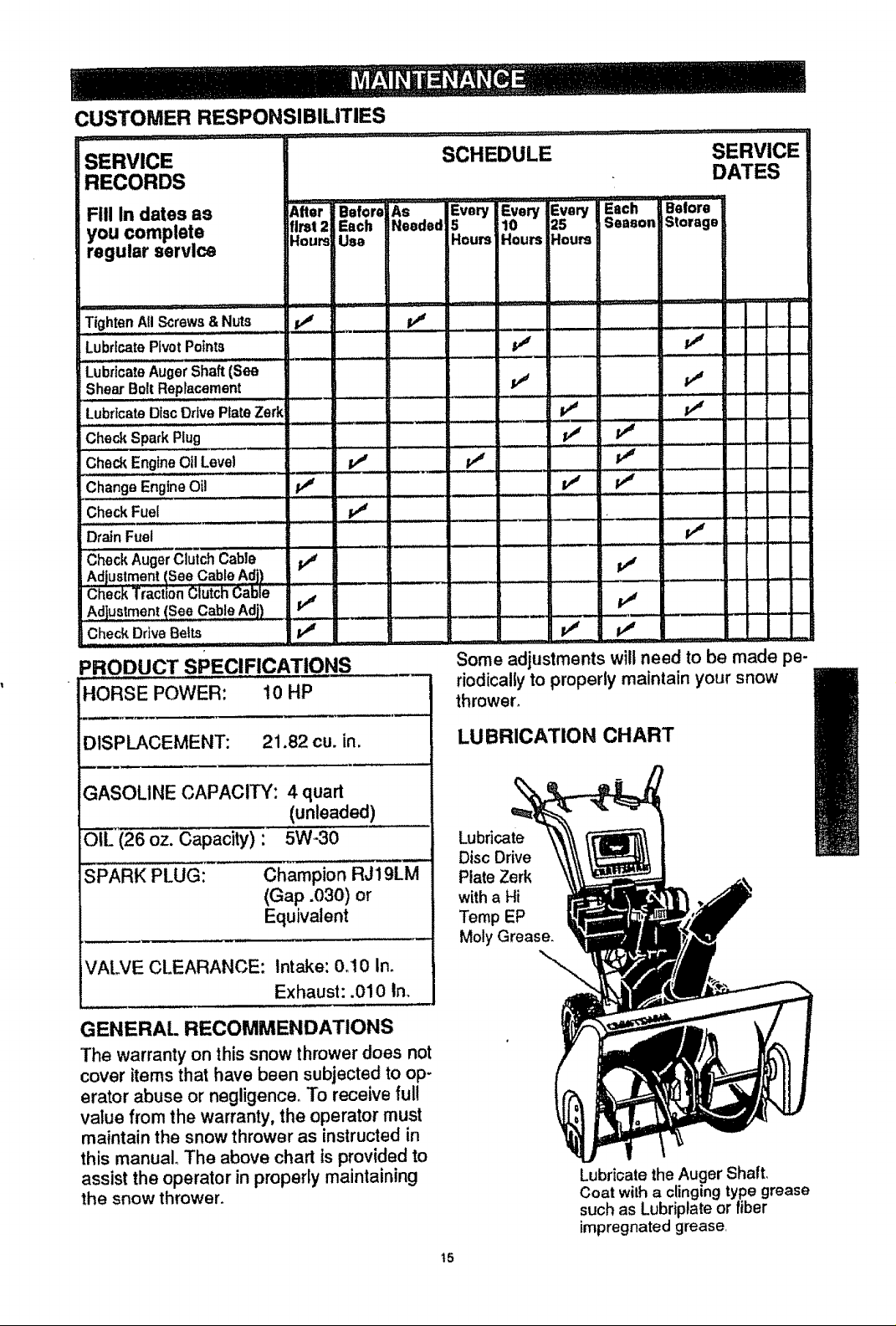
CUSTOMER RESPONSIBILITIES
SERVICE
SCHEDULE SERVICE
RECORDS
FEll In dates as Alter
you complete tlmt 2
regular service Houm
!Tighten All Screws &Nuts
Lubricate PivotPoints
Before A_ '" Every Every Every Each 'Elofore*
Each eded 5 10 25 Season Storage
Use Hours Hours .!ours
Lubricate AugerShaft(See
Shear Bolt Replacement
Lubricate DiscDrive Plate Zerk
CheckSparkPlug
CheckEngineOilLevel ..... tv_ ++_
ChangeEngineOil
Check Fuel
Drain Fuel I,j
• .......... m ...... u : ::: .....
(_heckAugerClutchCable p_ .... = "
Adjustment ISee Cable Adj) , = ................. • ....
Chec'k'Tra.ct+on_lutch C'able " ' ....... " : ................................
Adjustment (See CableAdj) _ ,I"4
Check Drive Belts p_
PRODUCT SPECIFICATIONS
HORSE POWER: 10 HP
Some adjustments willneed to be made pe-
riodicallyto properly maintain your snow
thrower+
ii ',, ,,_r., I I' I
, n ..
..... =_ - :: : f
v"
,, _' _, .......
DATES
+ .
B
DISPLACEMENT: 21.82 cu. in.
GASOLINE CAPACITY: 4 quart
(unleaded)
OIL (26 oz. Capacity) : 5W-30
SPARK PLUG: Champion RJ19LM
(Gap .030) or
Equivalent
VALVE CLEARANCE: Intake: 0.10 In.
Exhaust: .010 In.
GENERAL RECOMMENDATIONS
The warranty on this snow thrower does not
cover items that have been subjected to op-
erator abuse or negligence. To receive full
value from the warranty, the operator must
maintainthe snow thrower as instructed in
this manual. The above chart is providedto
assist the operator in properlymaintaining
the snow thrower.
LUBRICATION CHART
Lubricate
Disc Drive
Plate Zerk
witha Hi
Temp EP
Moly Grease.
Lubricate the Auger Shaft,
Coat witha clingingtype grease
such as Lubriptateor fiber
impregnated grease,
t5
SNOW THROWER
AFTER FIRST USE
• Check for any loose or damaged parts
after each use.
- Tighten any loose fasteners°
• Check and maintain the auger.
AFTER EACH USE
• Remove all snow and slush off the snow
thrower to prevent freezing of auger' or
controls.
. Check controls to make sure they are
functioning properly.
• If any parts are worn or damaged, replace
immediately.
SNOW TH ROWER
LUBRICATION - EVERY 10 HOURS
Auger Shaft - Using a hand grease gun,
lubricate the auger shaft zerk fittings (See
figure below) every ten (10) operating
hours. Each time a shear bolt is replaced
(See To Replace Auger Shear Bolt on
page 22), the auger shaft MUST be
greased,
A
For storageor when replacingshear
bolts, remove shear boltsand lubricate
auger shaft zerks. Rotate augers several
times on the shaft and reinstallthe shear
bolts.
See Lubrication Chart diagram on page
15 for lubrication points and type of lubri-
cant.
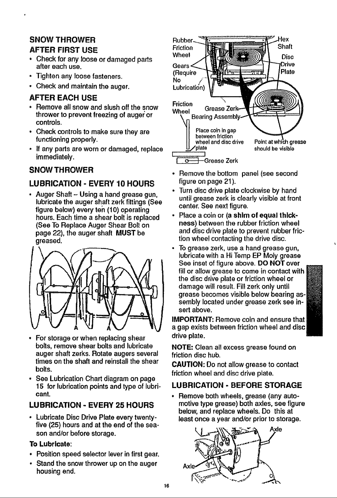
LUBRICATION - EVERY 25 HOURS
° Lubricate Disc Drive Plate every twenty-
five (25) hours and at the end of the sea-
son andlor before storage.
To Lubricate:
, Positionspeed selector lever infirstgear.
• Stand the snow thrower up on the auger
housing end.
Friction
Wheel
Shaft
Disc
we
(Require
No /
• , #
Lubncat_on)
Friction
Wheel Grease
Bearing
Placecoiningap
betweenfriction
wheelanddiscdrive
._,,/ptate
L !
_t--Grease Zerk
. Remove the bottom panel (see second
figure on page 21 ).
• Turn disc drive plate clockwise by hand
until grease zerk is clearly visible at front
center. See next figure.
° Place a coin or (a shim of equal thick-
ness) between the rubber friction wheel
and disc drive plate to prevent rubber fric-
tion wheel contacting the drive disc.
• To grease zerk, use a hand grease gun,
lubricate with a Hi Temp EP Moly grease
See inset of figure above. DO NOT over
fill or allow grease to come in contact with
the disc drive plate or friction wheel or
damage will result. Fill zerk only until
grease becomes visible below bearing as-
sembly located under grease zerk see in-
sert above.
Point grease
should be visible
Plate
IMPORTANT: Remove coin and ensure that
a gap exists between friction wheel and disc
drive plate.
NOTE: Clean all excess grease found on
friction disc hub,
CAUTION: Do not allowgrease to contact
friction wheel and disc drive plate.
LUBRICATION - BEFORE STORAGE
Remove both wheels, grease (any auto-
motive type grease) both axles, see figure
below, and replace wheels. Do this at
least once a year and/or priorto storage.
Axle
i6
LUBRICATION
, Hex Shaft and Gears- Hex shaft and
gears require no lubrication. All bearings
and bushings are lifetime lubricated and
require no maintenance.
NOTE: Any greasing or oiling of the above
components can cause contamination of
the friction wheel, if the discdrive plate or
friction wheel comes in contact withgrease
or oil, damage to the friction wheel wil!re-
suit.
Should grease or oi! come in contact with
the disc drive plate or friction wheel, be sure
to clean the plate and wheel thoroughly.
NOTE: For storage, the hex shaft and
gears should be wiped with 5W-30 motor oil
to prevent rusting. See first figure on this
page.
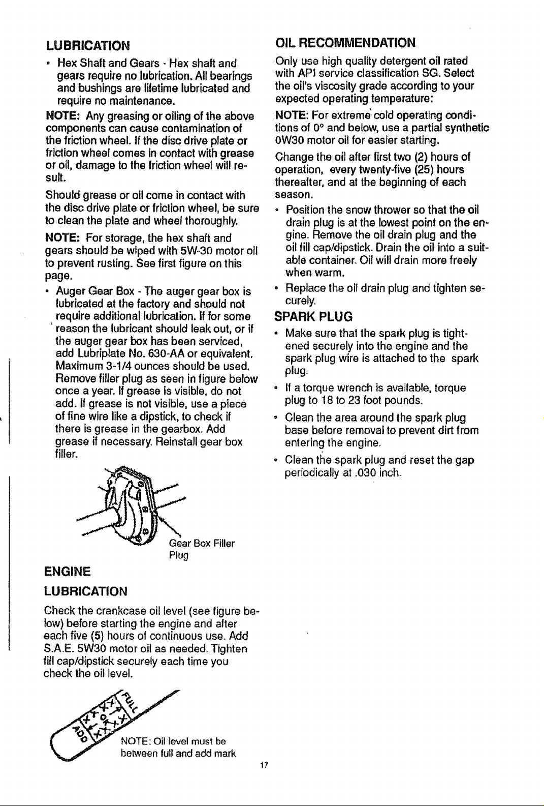
. Auger Gear Box - The auger gear box is
lubricated at the factory and should not
, require additional lubrication. If for some
reason the lubricant should leak out, or if
the auger gear box has been serviced,
add Lubriplate No. 630-AA or equivalent.
Maximum 3-1/4 ounces should be used.
Remove filler plug as seen in figure below
once a year. If grease is visible, do not
add. if grease is not visible, use a piece
of fine wire like a dipstick, to check if
there is grease in the gearbox. Add
grease if necessary. Reinstall gear box
filler.
OIL RECOMMENDATION
Only use high quality detergent oil rated
with API service classification SG. Select
the oil's viscosity grade according to your
expected operating temperature:
NOTE: For extreme' cold operating condi-
tions of 0° and below, use a partial synthetic
0W30 motor oil for easier starting.
Change the oil after first two (2) hours of
operation, every twenty-five (25) hours
thereafter, and at the beginning of each
season.
Position the snow thrower so that the oil
drain plug is at the lowest point on the en-
gineo Remove the oil drain plug and the
oil fill cap/dipstick. Drain the oil into a suit-
able container. Oil will drain more freely
when warm.
- Replace the oil drain plug and tighten se-
curely,
SPARK PLUG
Make sure that the spark plug is tight-
ened securely into the engine and the
spark plug wire is attached to the spark
plug_
• if a torque wrench is available, torque
plug to 18 to 23 foot pounds°
° Clean the area around the spark plug
base before removal to prevent dirt from
entering the engine.
• Clean the spark plug and reset the gap
periodically at .030 inch.
Gear Box Filler
Plug
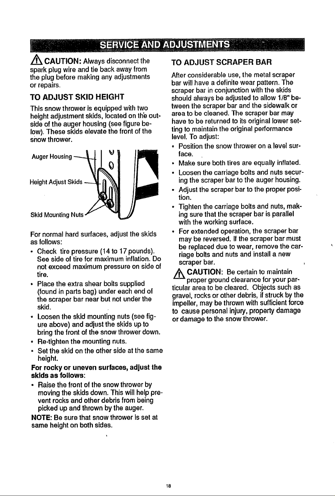
ENGINE
LUBRICATION
Check the crankcase oil level (see figure be-
low) before starting the engine and after
each five (5) hours of continuous use. Add
S.A.E. 5W30 motor oil as needed° Tighten
fill cap/dipstick securely each time you
check the oil level.
el must be
nd add mark
17
Z_ CAUTION: Always disconnect the
spark plug wire and tie back away from
the plug before making any adjustments
or repairs.
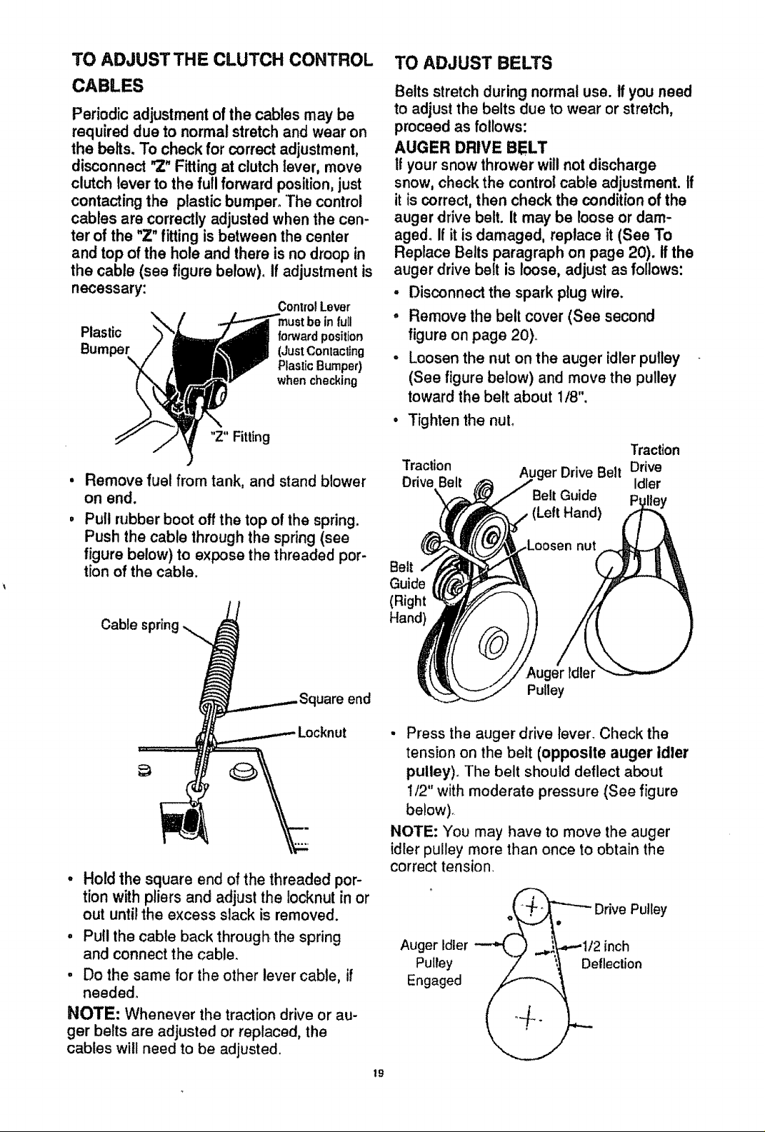
TO ADJUST SKID HEIGHT
*Thissnow thrower is equipped with two
height adjustment skids, located on th_ out-
side of the auger housing (see figure be-
low). These skids elevate the front of the
snow thrower.
Auger Housing
Height Adjust Skids
Skid Mounting Nuts
For normal hard surfaces, adjust the skids
as tollows:
° Check tire pressure (14 to 17 pounds).
See side of tire for maximum inflation.Do
not exceed maximum pressure on side of
tire.
• Place the extra shear bolts supplied
(foundin parts bag) under each end of
the scraper bar near but not under the
skid°
• Loosen the skid mounting nuts (see fig-
ure above) and adjust the skids upto
bring the front of the snow thrower down.
• Re-tighten the mounting nuts.
• Set the skid on the other side at the same
height.
For rocky or uneven surfaces, adjust the
skids as follows:
• Raise the front of the snow thrower by
movingthe skids down. This will help pre-
vent rocks and other debris from being
picked up and thrown by the auger_
NOTE: Be sure that snow thrower is set at
same height on both sides.
TO ADJUST SCRAPER BAR
After considerable use, the metal scraper
bar will have a definite wear pattern. The
scraper bar in conjunction with the skids
should always be adjusted to allow 1/8" be-
tween the scraper bar and the sidewalk or
area to be cleaned. The scraper bar may
have to be returned to its original lower set-
ting to maintain the original performance
level. To adjust:
• Position the snow thrower on a level sur-
face.
o Make sure both tires are equally inflated.
• Loosen the carriage bolts and nuts secur-
ing the scraper bar to the auger housing.
• Adjust the scraper bar to the proper posi-
tion.
• Tighten the carriage bolts and nuts, mak-
ing sure that the scraper bar is parallel
with the working surface.
• For extended operation, the scraper bar
may be reversed. If the scraper bar must
be replaced due to wear, remove the car-
riage bolts and nuts and install a new
scraper bar.
CAUTION: Be certain to maintain
proper ground clearance for your par-
ticular area to be cleared, Objects such as
gravel, rocks or other debris, if struck by the
impeller, may be thrown with sufficient force
to causepersonalinjury,property damage
or damage to the snow thrower,
18
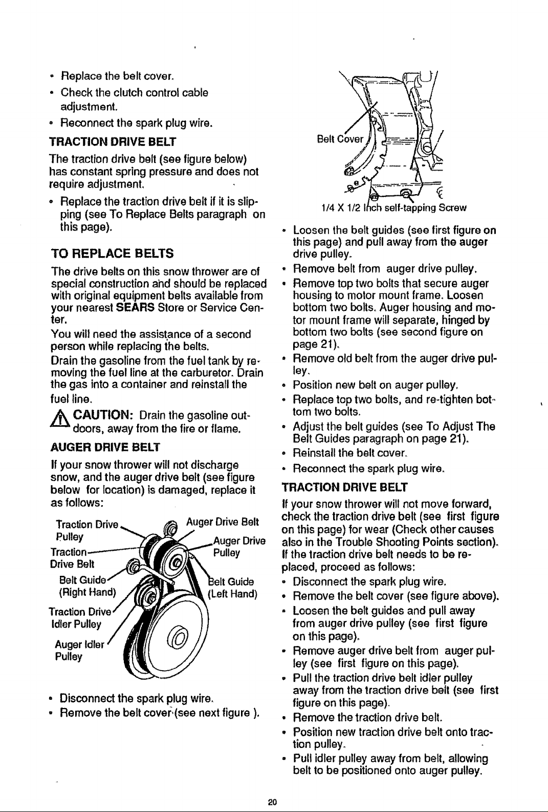
TO ADJUSTTHE CLUTCH CONTROL
CABLES
Periodic adjustment of the cables may be
required due to normal stretch andwear on
the belts. To check for correct adjustment,
disconnect "Z"Fitting atclutch lever, move
clutch lever to the full forward position,just
contacting the plastic bumper°"Thecontrol
cables are correctly adjusted when the cen-
ter of the "Z"fitting is between the center
and top of the hole and there is no droop in
the cable (see figure below)° If adjustmentis
necessary:
ControlLever
infull
Plastic forwardposition
(JustContacting
PlasticBumper)
when checking
"Z" Fitting
Remove fuel from tank, and stand blower
on end.
Pull rubber boot off the top of the spring.
Push the cable through the spring (see
figure below) to expose the threaded por-
tion of the cable.
TO ADJUST BELTS
Belts stretchduring normal use. If you need
to adjustthe belts due to wear or stretch,
proceed as follows:
AUGER DRIVE BELT
If your snowthrower will not discharge
snow,check the controlcable adjustment. If
itis correct,then check the conditionof the
auger drive belt. It may be loose or dam-
aged. If it isdamaged, replace it (See To
Replace Belts paragraph on page 20). Ifthe
auger drive belt is loose, adjust asfollows:
• Disconnect the spark plug wire.
° Remove the belt cover (See second
figure on page 20)_
° Loosen the nut on the auger idler pulley
(See figure below) and move the pulley
toward the belt about 1/8".
Tighten the nuL
Traction
Traction Auger Drive Belt Drive
Drive Belt Idler
Belt Guide ey
(Left Hand)
nut
Belt
Guide
(Right
Hand)
Cablespring._,_ Squareend
======_/_._ Locknut
° Hold the square end of the threaded por-
tion with pliers and adjust the Iocknut in or
out until the excess slack is removed.
o Pull the cable back through the spring
and connect the cable.
. Do the same for the other lever cable, if
needed.
NOTE: Whenever the traction drive or au-
ger belts are adjusted or replaced, the
cables will need to be adjusted.
,Auger idler
Pulley
• Press the auger drive lever. Check the
tension on the belt (opposite auger idler
pulley). The belt should deflect about
!/2" with moderate pressure (See figure
below).
NOTE: You may have to move the auger
idler pulley more than once to obtain the
correct tension.
" _.+_2,_ Drive Pulley
Auger idler "-""L__) ..._--'1/2 inch
Engaged
Pulley __ ._Deflection
19
- Replace the belt cover°
• Check the clutch control cable
adjustment.
o Reconnect the spark plug wire.
TRACTION DRIVE BELT
The traction drive belt (see figure below)
has constant spring pressure and does not
require adjustment.
• Replace the traction drive belt if it is slip-
ping (see To Replace Belts paragraph on
this page).
TO REPLACE BELTS
The drive belts on this snow thrower are of
special construction ahd should be replaced
with original equipment belts available from
your nearest SEARS Store or Service Cen-
ter.
You wilt need the assistance of a second
person while replacing the belts.
Drain the gasoline from the fuel tank by re-
moving the fuel line at the carburetor. Drain
the gas into a container and reinstall the
fuel line.
,/_ CAUTION: Drain the gasoline out-
doors, away from the fire or flame.
AUGER DRIVE BELT
Ifyour snow thrower will not discharge
snow, and the auger drive belt (see figure
below for location) isdamaged, replace it
as follows:
Traction Drive Auger Drive Belt
Pulley
Traction Pulley
Drive Belt
Belt Guide
(Right Hand) (Left Hand)
Traction
Idler Pulley
Auger
Pulley
° Disconnect the spark plug wire.
, Remove the belt covm:.(see next figure).
\
/
1/4 X 1/2
• Loosen the belt guides (see tirst figure on
this page) and pull away from the auger
drive pulley.
• Remove belt from auger drive pulley,
• Remove top two bolts that secure auger
housing to motor mount frame. Loosen
bottom two bolts. Auger housing and mo-
tor mounl frame will separate, hinged by
bottom two bolts (see second figure on
page 2t).
, Remove old belt from the auger drive pul-
ley.
o Position new belt on auger pulley,
° Replace top two bolts, and re-tighten bet..
tom two bolts.
° Adjust the belt guides (see To Adjust The
Belt Guides paragraph on page 21)o
° Reinstall the belt cover.
, Reconnect the spark plug wire.
TRACTION DRIVE BELT
If your snow thrower will not move forward,
check the traction drive belt (see first figure
on this page) for wear (Check other causes
also in the Trouble Shooting Points section).
If the traction drive belt needs to be re-
placed, proceed as follows:
• Disconnect the spark plug wire.
• Remove the belt cover (see figure above).
° Loosen the belt guides and pull away
from auger drive pulley (see first figure
on this page).
- Remove auger drive belt from auger pul-
ley (see first figure on this page).
- Pul! the traction drive belt idier pulley
away from the traction drive belt (see first
figure on this page).
• Remove the traction drive belt.
• Position new traction drive belt onto trac-
tion pulley°
• Pult idler pulley away from belt, allowing
belt to be positioned onto auger pulley.
=ppingScrew
20
. Release idler pulley, Ensure idler pulley
is properly engaged with belt,
° Reinstall auger drive belt.
° Adjust the belt guides and tighten mount-
ing screws (see To Adjust The Belt
Guides paragraph on this page),
° Adjust idler on auger belt.
- Reinstall the belt cover_
° Reconnect the spark plug wire,
• Disconnect the spark plug wire.
• Drain the gaso}ine from the gas tank.
- Stand snow thrower on the auger housing
end.
• Remove the bottom panel (see figure be-
low)_
Remove Top Bolts
(Each Side)
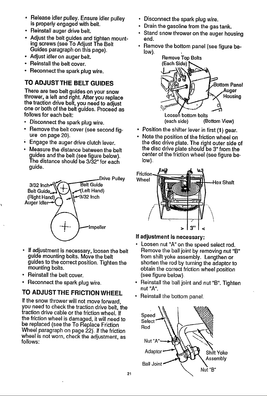
TO ADJUST THE BELT GUIDES
There are two belt guides on your snow
thrower, a left and right, After you replace
the traction drive belt, you need to adjust
one or both of the belt guides. Proceed as
follows for each belt:
• Disconnect the spark plug wire.
• Remove the belt cover (see second fig-
ure on page 20).
-' Engage the auger drive clutch lever.
• Measure the distance between the belt
guides and the belt (see figure below).
The distance should be 3132" for each
guide.
inch.,,_.,._.,...._DriveV ..I____'= Putley
3/32
Belt Guide.._ ",_T_\_"( Left Hand)
(Right Hand)(_-- .#:\_,_3/32Inch
Housing
Looser bottom bolts
(each side) (Bottom View)
@
Position the shifter lever in first (1) gear.
@
Note the position of the friction wheel on
the disc drive plate, The right outer side of
the disc drive plate should be 3 from the
center of the friction wheel (see figure be,.
low),
Wheel
Shaft
Panel
• If adjustment is necessary, loosen the belt
guide mounting bolls. Move the belt
guides to the correct position. Tighten the
mounting bolts.
° Reinstall the belt cover.
° Reconnect the spark plug wire°
TO ADJUST THE FRICTION WHEEL
if the snow thrower wilt not move forward,
you need to check the traction drive belt, the
traction drive cable or the friction wheel. If
the friction wheel is damaged, it will need to
be replaced (see the To Replace Friction
Wheel paragraph on page 22). If the friction
wheel is not worn, check the adjustment, as
follows:
If adjustment Is necessary:
• Loosen nut "A" on the speed select rod.
Remove the ball joint by removing nut "B"
from shift yoke assembly. Lengthen or
shorten the rod by turning the adaptor to
obtain the correct friction wheel position
(see figure below).
• Reinstall the ball joint and nut "B". Tighten
nut "A".
Reinstall the bottom panel°
Speed
Rod
Nut
Ada Shift Yoke
Assembly
Bait Joint k_. Nut "B"
21
\
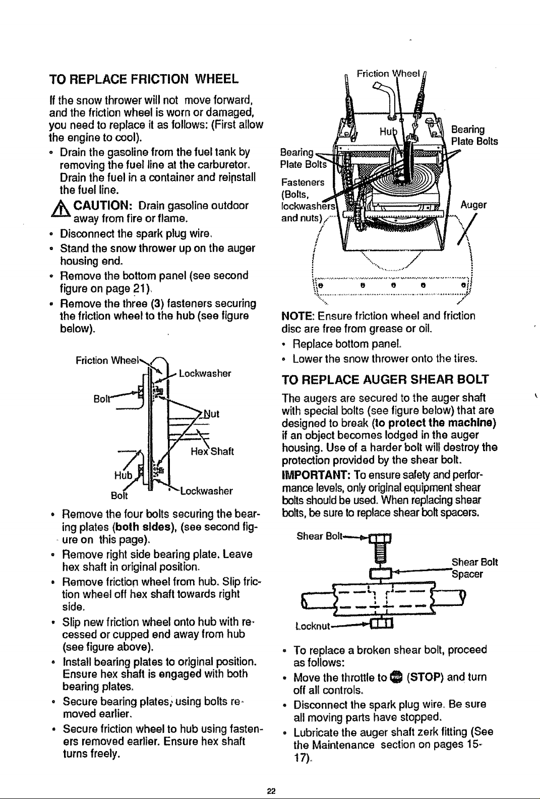
TO REPLACE FRICTION WHEEL
If the snow thrower wil! not move forward,
and the friction wheel is worn or damaged,
you need to replace it asfollows: (Firstallow
the engine to cool).
o Drain the gasoline from the fuel tank by
removing the fuel line at the carburetor.
Drain the fuel in a container and reipstall
the fuel line.
CAUTION: Drain gasoline outdoor
away from fire or flame.
° Disconnect the spark plug wire,
° Stand the snow thrower up on the auger
housing end°
° Remove the bottom panel (see second
figure on page 21).
° Remove the three (3) fasteners securing
the friction wheel to the hub (see figure
below).
Friction Wheel',,_!'-'_I
r{[_= Lockwasher
Bol i_,=!
Shaft
Bo_ u "_ Lockwasher
• Remove the four bolts securing the bear-
ing plates (both sides), (see second fig-
ure on this page)_
• Remove right side bearing plate, Leave
hex shaft in originalposition.
° Remove friction wheel from hub. Slip fric-
tion wheel off hex shaft towards right
side.
° Slip new friction wheel onto hub with re-
cessed or cupped end away from hub
(see figure above).
, Install bearing plates to original position.
Ensure hex shaft is engaged with both
bearing ptates_
° Secure bearing plates; using bolts re-
moved earlier.
Secure friction wheel to hub using fasten-
ers removed earlier. Ensure hex shaft
turns freely.
Friclion
Bearing
Plate Bolts
Bearin
Plate
Fasteners
(Bolts,
Auger
and nuts),/ .....
/
/
._._e e e e e
.........................................................................iJ
NOTE: Ensure frictionwheel and friction
disc are free from grease or oil.
• Replace bottom panel
° Lower the snow thrower onto the tires.
TO REPLACE AUGER SHEAR BOLT
The augers are secured to the auger shaft
with special bolts (see figure below) that are
designed to break (to protect the machine)
if an object becomes lodged in the auger
housing. Use of a harder bolt will destroy the
protection provided by the shear bolt.
IMPORTANT: To ensure safety and perfor-
mance levels,only original equipment shear
boltsshouldbe used. When replacing shear
bolts,be sureto replace shear bolt spacers.
Shear Bolt._
Shear Bolt
° To replace a broken shear bolt, proceed
as follows:
, Move the throttle to I_1 (STOP) and turn
off all controls.
, Disconnect the spark plug wire° Be sure
all moving parts have stopped.
• Lubricate the auger shaft zerk fitting (See
the Maintenance section on pages 15-
17)+
22
 Loading...