

Craftsman 536886331 Owner’s Manual
OWNER'S
CRAFTSMAN®
10 HORSEPOWER
29" DUAL STAGE
MANUAL
MODEL NO.
536.886331
HOW TO ORDER
REPAIR PARTS
120V. ELECTRIC START
SNOW THROWER
WHEN ORDERING REPAIR PARTS, ALWAYS
Each SNOW THROWER has its own MODEL
NUMBER found on the engine mount frame.
Each ENGINE has its own MODEL NUMBER
found on the BLOWER HOUSING.
Always mention these MODEL NUMBERS when
requesting service or Repair Parts for your SNOW
THROWER.
All parts may be orderedthrough Sears, Roebuck
and Company Service Centers and most Retail
Stores,
GIVE THE FOLLOWING INFORMATION:
* PRODUCT - "SNOW THROWER"
* MODEL NUMBER - 536.886331
* ENGINE MODEL NUMBER - 143.941001
* PART NUMBER
* PART DESCRIPTION
"Your Sears merchandise has added value when you
consider that Sears has service units nationwide staffed
with Sears trained technicians...Professional lechnicians
specifically trained on Sears products, having the parts,
tools and equipment to ensure that we meet our pledge
to you...we service what we sell."
SEARS, ROEBUCK AND CO., Hoffman Estates, IL 60179
334224 07/28/94 Printed In U.S.A.
SAFETY RULES
CAUTION: ALWAYS DISCONNECT SPARK PLUG WIRE AND A
&
SAFETY STANDARDS REQUIRE OPERATOR PRESENCE CONTROLS TO MINIMIZE THE
RISK OF INJURY. YOUR SNOW THROWER IS EQUIPPED WITH SUCH CONTROLS. DO NOT
ATTEMPT TO DEFEAT THE FUNCTION OF THE OPERATOR PRESENCE CONTROL UNDER
ANY CIRCUMSTANCES.
PLACE WIRE WHERE IT CANNOT CONTACT SPARK PLUG
TO PREVENT ACCIDENTAL STARTING WHEN SETTING-UP
TRANSPORTING, ADJUSTING OR MAKING REPAIRS.
IMPORTANT
BEFORE USE
• Read the Owner's Manual carefully. Be thor-
oughly familiar with the controls and the proper
use of the snow thrower. Know how to stop the
snow thrower and disengage the controls
quickly.
• Do not operate the snow thrower without
wearing adequate winter outer garments.
Wear footwear that will improve footing on
slippery surfaces.
• Keep the area of operation clear of all persons,
particularly small children, and pets.
• Thoroughly inspect the area where the snow
thrower is to be used and remove all doormats,
sleds, boards, wires, and other foreign objects.
• Use extension cords and receptacles as
specified by the manufacturer for all snow
throwers with electric drive motors or with
factory-installed or optional starting motors.
• Use only attachments and accessories ap-
proved by the manufacturer of the snow thrower
(such as electric starter kits, etc.).
• Never operate the snow thrower without good
visibility or light. Always be sure of your footing,
and keep a firm hold on the handles. Walk;
never run.
• This snow thrower is for use on sidewalks,
driveways, and other ground level surfaces.
CAUTION should be exercised while using on
steep stoping surfaces. DO NOT USE SNOW
THROWER ON SURFACES ABOVE
GROUND LEVEL such as roofs of residences,
garages, porches or other such structures or
buildings.
• Check all bolts at frequent intervals for proper
tightness to be sure the snow thrower is in safe
working condition.
• Disengage clutch before starting the engine.
• Let engine and snow thrower adjust to outdoor
temperatures before starting to clear snow.
FUEL SAFETY
• Handle fuel with care; it is highly flammable.
• Use an approved fuel container.
• Check fuel supply before each use, allowing
space for expansion as the heat of the engine
and/or sun can cause fuel to expand.
• Fill fuel tank outdoors with extreme care. Never
fill fuel tank indoors.
• Replace fuel tank cap securely and wipe up
spilled fuel.
• Never remove fuel tank cap or add fuel to a
running engine or hot engine.
• Never store fuel or snow thrower with fuel in the
tank inside a building where fumes may reach
an open flame or spark.
OPERATING SAFETY
• Never allow children or young teenagers to
operate the snow thrower and keep them away
while it is operating. Never allow adults to
operate the snow thrower without proper in-
struction. Do not carry passengers.
• Always wear safety glasses or eye shields
during operation or white performing an
adjustment or repair to protect eyes from for-
eign objects that may be thrown from the snow
thrower.
• Exercise extreme caution when operating on or
crossing gravel drives, walks, or roads. Stay
alert for hidden hazards or traffic.
• Do not put hands or feet near or under rotating
parts. Keep clear of the discharge opening at
all times.
• Exercise caution to avoid slipping or falling,
especially when operating in reverse or back-
ing up.
• Do not clear snow across the face of slopes.
Exercise caution when changing direction on
slopes. Do not attempt to clear steep slopes.
• Never operate the snow thrower without
proper guards, plates or other safety protective
devices in place.
SAFETY RULES
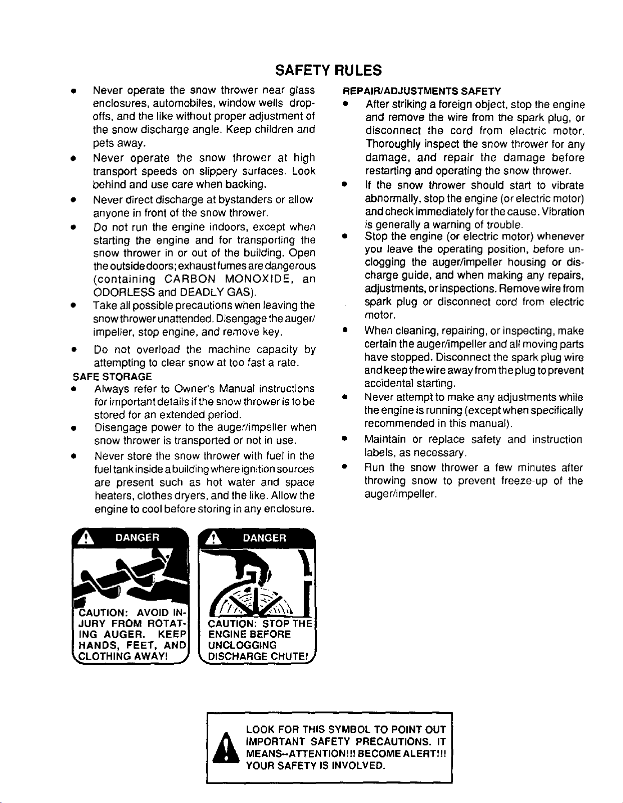
• Never operate the snow thrower near glass
enclosures, automobiles, window wells drop-
offs, and the like without proper adjustment of
the snow discharge angle. Keep children and
pets away.
• Never operate the snow thrower at high
transport speeds on slippery surfaces. Look
behind and use care when backing.
• Never direct discharge at bystanders or allow
anyone in front of the snow thrower.
• Do not run the engine indoors, except when
starting the engine and for transporting the
snow thrower in or out of the building. Open
the outside doors; exhaust fumes are dangerous
(containing CARBON MONOXIDE, an
ODORLESS and DEADLY GAS).
• Take all possible precautions when leaving the
snow thrower unattended. Disengage the auger/
impeller, stop engine, and remove key.
• Do not overload the machine capacity by
attempting to clear snow at too fast a rate.
SAFE STORAGE
• Always refer to Owner's Manual instructions
for important details if the snow thrower is to be
stored for an extended period.
• Disengage power to the auger/impeller when
snow thrower is transported or not in use.
• Never store the snow thrower with fuel in the
fuel tank inside a building where ignition sources
are present such as hot water and space
heaters, clothes dryers, and the like. Allow the
engine to cool before storing in any enclosure.
REPAIR/ADJUSTMENTS SAFETY
• After striking a foreign object, stop the engine
and remove the wire from the spark plug, or
disconnect the cord from electric motor.
Thoroughly inspect the snow thrower for any
damage, and repair the damage before
restarting and operating the snow thrower.
• If the snow thrower should start to vibrate
abnormally, stop the engine (or electric motor)
and check immediately for the cause. Vibration
is generally a warning of trouble.
• Stop the engine (or electric motor) whenever
you leave the operating position, before un-
clogging the auger/impeller housing or dis-
charge guide, and when making any repairs,
adjustments, or inspections. Remove wire from
spark plug or disconnect cord from electric
motor.
• When cleaning, repairing, or inspecting, make
certain the auger/impeller and all moving parts
have stopped. Disconnect the spark plug wire
and keep the wire away from the plug to prevent
accidental starting.
• Never attempt to make any adjustments while
the engine is running (except when specifically
recommended in this manual).
• Maintain or replace safety and instruction
labels, as necessary.
• Run the snow thrower a few minutes after
throwing snow to prevent freeze-up of the
auger/impeller.
CONGRATULATIONS on your purchase of a Sears
_rattsman Snow Thrower. It has been designed, engi-
neered a_d manufactured to give you the best poss;ble
dependability and performance.
Should you experience any problem you cannot easily
remedy, please contact your nearest Sears Service
Center/Department. Sears has competent, well-trained
technicians and the proper tools to service or repair this
unit.
Please read and retain this manual. The instructionswill
enab(e you to assemble and maintain your snow thrower
oropedy. Always observe the "SAFETY RULES."
MODEL
NUMBER 536.886331
SERIAL
NUMBER
DATE OF
PURCHASE
THE MODEL AND SERIAL NUMBERS WILL BE
FOUND ON A DECAL ATTACHED TO THE REAR
OF THE SNOW THROWER HOUSING.
YOU SHOULD RECORD BOTH SERIAL NUMBER
AND DATE OF PURCHASE AND KEEP IN A SAFE
PLACE FOR FUTURE REFERENCE.
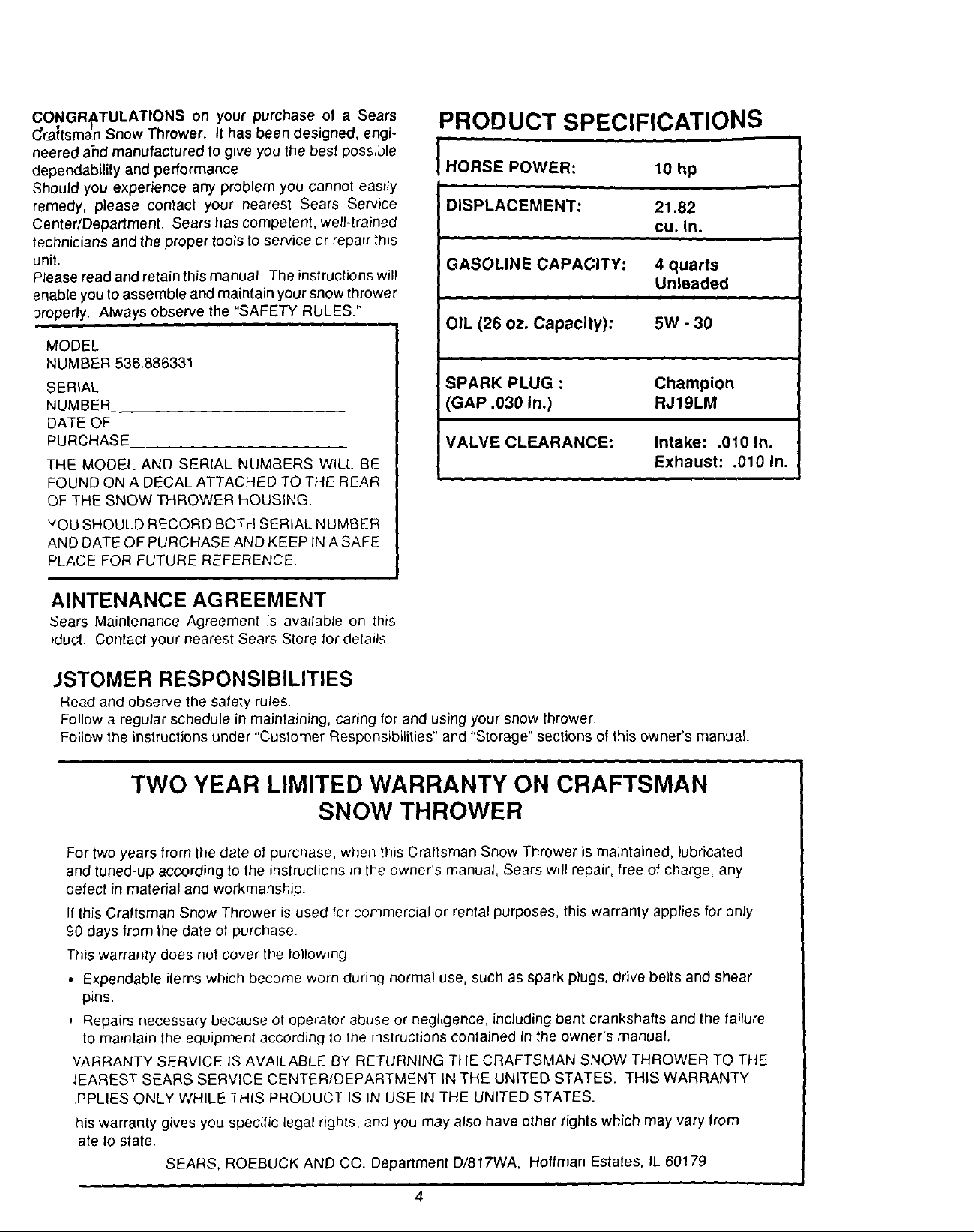
PRODUCT SPECIFICATIONS
i =
HORSE POWER: 10 hp
DISPLACEMENT: 21.82
cu, in.
GASOLINE CAPACITY:
OIL (26 oz. Capacity): 5W - 30
SPARK PLUG :
(GAP .030 In.)
VALVE CLEARANCE:
4 quarts
Unleaded
Champion
RJ19LM
Intake: .010 In.
Exhaust: .010 In.
AINTENANCE AGREEMENT
Sears Maintenance Agreement is available on this
)duct. Contact your nearest Sears Store for details.
JSTOMER RESPONSIBILITIES
Read and observe the safety rules.
Follow a regular schedule in maintaining, caring for and using your snow thrower.
Follow the instructions under "Customer Responsibilities" and "Storage" sections of this owner's manual.
TWO YEAR LIMITED WARRANTY ON CRAFTSMAN
SNOW THROWER
For two years from the date of purchase, when this Craftsman Snow Thrower is maintained, lubricated
and tuned-up according to the instructions in the owner's manual, Sears will repair, free of charge, any
defect in material and workmanship.
If this Craftsman Snow Thrower is used for commercial or rental purposes, this warranty applies for only
90 days from the date of purchase.
This warranty does not cover the following:
• Expendable items which become worn during normal use, such as spark plugs, drive belts and shear
pins.
Repairs necessary because of operator abuse or negligence, including bent crankshafts and the failure
to maintain the equipment according to the instructions contained in the owner's manual.
VARRANTY SERVICE IS AVAILABLE BY RETURNING THE CRAFTSMAN SNOW THROWER TO THE
_EAREST SEARS SERVICE CENTER/DEPARTMENT IN THE UNITED STATES. THIS WARRANTY
,PPLIES ONLY WHILE THIS PRODUCT IS IN USE IN THE UNITED STATES.
his warranty gives you specific legal rights, and you may also have other rights which may vary from
ate to state.
SEARS, ROEBUCK AND CO. Department D/817WA, Hoffman Estates, IL 60179
TABLE OF CONTENTS
SAFETY RULES ........................................ 2,3
PRODUCT SPECIFICATIONS ...................... 4
CUSTOMER RESPONSIBILITIES ..... 4,17-19
WARRANTY .................................................. 4
TABLE OF CONTENTS ................................ 5
INDEX ........................................................... 5
ASSEMBLY .............................................. 6-10
OPERATION .......................................... 1;-16
SERVICE AND ADJUSTMENTS ........... 20-26
STORAGE ................................................... 27
TROUBLE SHOOTING ............................... 28
REPAIR PARTS (SNOW THROWER)...29-40
REPAIR PARTS (ENGINE) .................... 41-45
PARTS ORDERING/SERVICE ................... 48
INDEX
A
Adjustment:
Auger ............................................. 21
Belt ................................................ 21
Belt Guide ...................................... 23
Cable ............................................. 21
Carburetor ..................................... 26
Friction Wheel ................................ 23
Spark Plug ..................................... 25
Traction and Auger ........................ 21
Assembly:
Check List ...................................... 10
Control Cables ................................. 9
Crank Assembly .............................. 8
Headlight ......................................... 9
Shifter Lever and Shifter Knob ...... 10
Skid Height Adjustment ............. 7, 20
Snow Chute ..................................... 8
Unpacking ........................................ 7
B
Belts:
Adjust Belts.................................... 21
Belt Guide Adjustment ................... 23
Belt Maintenance ........................... 18
Replace Belts .......................... 22, 23
C
CabLes,Clutch ........................ 9,10, 21
Carburetor: ....................................... 25
Choke ......................... 11, 12, 14,15,16
Clutch, Levers ............................ 11, 12
Controls:
Engine ......................... 11, 12, 14, 15
Snow Thrower ............................... 11
Crank:
Adjusting Rod ............................ 8, 20
Assembly ......................................... 8
Operation ....................................... 12
Customer Responsibilities ........ 4,17-19
Agreement ....................................... 4
Auger Gear Box ............................ 18
Auger Shaft ................................... 18
Engine ........................................... 19
General Recommendations .......... 18
Hex Shaft and Gears ..................... t 8
Spark Plug ..................................... 19
D
Drive,Auger.....................................12
Drive, Traction .................................12
Deflector, Snow Chute ..................... 12
E
Engine:
Control .................... 10, 11, 13, 14,15
Oil Cap ..................................... 13, 19
Oil Change ..................................... 19
Oil Level ................................... 13, 19
Oil Type ............................... 4, 13, 19
Speed Governor ............................ 25
Starting, Electrically ....................... 14
Starting, Manually .......................... 16
Storage .......................................... 27
F
Fuel, Type .................................... 4, 13
Fuel, Storage .............................. 13, 27
Friction Wheel:
Adjustment ..................................... 23
Replacement ................................. 24
G
Gears:
Auger Gear Box ....................... 18, 19
Hex Shaft ....................................... 18
H
Handle, Upper and Lower .................. 8
Headlight ............................................ 9
Height Adjust Skids ...................... 7, 20
Hex Shaft ................................... 18, 19
I
Ignition, Key ................... 10, 11, 13, 14
Index .................................................. 5
L
Levers:
Auger Drive Clutch ........ 9, 11, 12, 21
Choke .......................... 11, 12, 14, 15
Shifter ...................................... 10, 12
Throttle Control ............ 11, 12, 14, 15
Traction Drive Clutch ..... 9, 11, 12, 21
Lubrication:
Auger Gear Box ............................. 19
Auger Shaft ............................... 17,18
Chain and Sprockets ................ 17,18
Chart .............................................. 17
Disc Drive Plate ............................. 19
Engine ..................................... 13, 19
Hex Shaft and Gears ..................... 19
Weight Transfer System ................ 18
O
Oil:
Engine ................................. 4, 13, 19
Extreme Cold Weather ............. 13,19
Storage .......................................... 27
Type ..................................... 4, 13, 19
Operation:
Engine Controls ............ 11, 12, 14,15
Operating Snow Th rower... 12, 13, 16
Operating Tips ............................... 16
Starting the Engine, Electric .......... 14
Starting the Engine, Recoil ....... 15,16
Snow Thrower Controls ............ 11-13
P
Parts ............................................ 29-40
Primer Button ................. 11, 12, 14, 15
R
Repair/Replacement Parts .......... 29-40
Recoil Starter ............................... 15,16
Replacements:
Auger Shear Bolt ........................... 25
Belts ......................................... 22, 23
Friction Wheel ............................... 24
S
Safety Rules ................................... 2, 3
Service and Adjustments:
Auger Housing Height ............... 7, 20
Auger Shear Bolt ........................... 25
Belts ......................................... 21-23
Belt Guide ...................................... 23
Belt Replacements .................. 22, 23
Cable ................................... 9; 10, 21
Carburetor ............................... 25, 27
Friction Wheel .......................... 23, 24
Spark Plug ..................................... 26
Spark Plug .................................. 19, 26
Specifications ..................................... 4
Speed Governor ............................... 26
Starting the Engine:
Electric Start .................................. 14
Recoil Start ............................... 15,16
Stopping the Engine ............. 12, 14, 15
Stopping the Snow Thrower ............. 12
Shipping Carton .................................. 7
Skid Height ................................... 7, 20
Shifter Lever ................................ 10-12
Shear Bolts ....................................... 25
Storage ............................................. 27
T
Table of Contents ............................... 5
Trouble Shooting Chart .................... 28
Tools for Assembly ............................. 6
Traction Drive Belt ...................... 21, 23
W
Warranty ............................................. 4
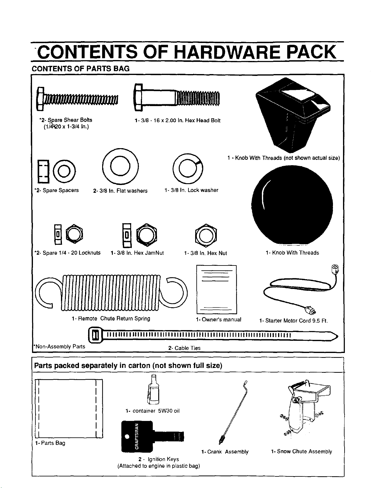
CONTENTS OF HARDWARE PACK
CONTENTS OF PARTS BAG
"2- Spare Shear Bolts 1- 3/8 - 16 x 2.00 In. Hex Head Bolt
(1/4_0 x 1-3/4 In.)
1 - Knob With Threads (not shown actual size)
©
*2- Spare Spacers 2- 3/8 In. Flat washers
1- 3/8 In. Lock washer
©
"2- Spare 1/4 - 20 Locknuts 1- 3/8 In. Hex JamNut
1- Remote Chute Return Spring 1- Owner's manual
_ IIIIIIIIIIIIIIIIIIIIIIIIIIIIIIIIIIIIIIIIIIIIIIIIIIIIIIIIIIIIIIIIIII )
"Non-AssemblyParts 2- Cable Ties
Parts packed separately in carton (not shown full size)
1- 3/8 In. Hex Nut
1- Knob With Threads
1- Starter Motor Cord 9.5 Ft.
I
1-Parts Bag
1. container 5W30 oil
2 - IgnitionKeys
(Attached to engine in plastic bag)
1- Crank Assembly
1- Snow Chute Assembly
ASSEMBLY
TOOLS REQUIRED FOR ASSEMBLY
1 - Knife (to cut carton and plastic ties/
2 - 1/2 inch wrenches (or adjustable wrenches)
2 - 9/16 inch wrenches (or adjustable wrenches}
2- 3/4 inch wrenches (or adjustable wrenchesl
1 - Pliers (to spread cotter pin)
1- Screwdriver
1 - Measuring tape or ruLer
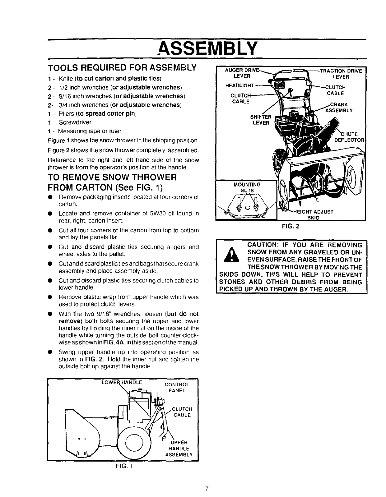
Figure 1 shows the snow thrower inthe shipping position
Figure 2 shows the snow thrower completely assembled.
Reference to the right and left hand side of the snow
thrower is from the operator's position at the handle.
TO REMOVE SNOW THROWER
FROM CARTON (See FIG. 1)
• Remove packaging inserts located at lour corners of
carton.
• Locate and remove container o! 5W30 oil found in
rear, right, carton insert.
• Cut all four corners of the carton from top to bottom
and lay the panels llat.
• Cut and discard plastic ties securing augers and
wheel axles to the pallet.
• Cutand discard plasticties and bagsthat secure crank
assembly and place assembly aside
• Cut and discard plastic ties securing clutch cables to
lower handle.
• Remove plastic wrap from upper handle which was
used to protect clutch levers
• With the two 9/16" wrenches, loosen (but do not
remove) both bolts securing the upper and lower
handles by holding the inner nut on the inside ot the
handle while turning the outside boll counter-clock-
wise as shown in FIG. 4A, in this section of the manual.
• Swing upper handle up into operating position as
shown in FIG. 2. Hold the inner nut and tighten [ne
outside bolt up against the handle
LEVER LEVER
CABLE
CABLE
MBLY
SHIFTER
LEVER
DEFLECTOR
FIG. 2
CAUTION: IF YOU ARE REMOVING
SNOW FROM ANY GRAVELED OR UN-
EVEN SURFACE, RAISE THE FRONT OF
THE SNOW THROWER BY MOVING THE
SKIDS DOWN. THIS WILL HELP TO PREVENT
STONES AND OTHER DEBRIS FROM BEING
PICKED UP AND THROWN BY THE AUGER.
LOWEr HANDLE
FIG. 1
CONTROL
PANEL
CLUTCH
UPPER
HANDLE
ASSEMBLY
7
ASSEMBLY
• Assemble the snow chute.
• Rollsnow throweroff the skid by pulling on the handle.
• Properly dispose of discarded packaging.
HOW TO SET UP YOUR SNOW
THROWER
Your snow thrower is equipped with height adjust skids
(See FIG. 2) on the outside of the auger housing. To adjust
the skid height, see To Adjust Skid Height paragraph inthe
Service & Adjustments section of this manual. (See Fig-
ure 1 page 20).
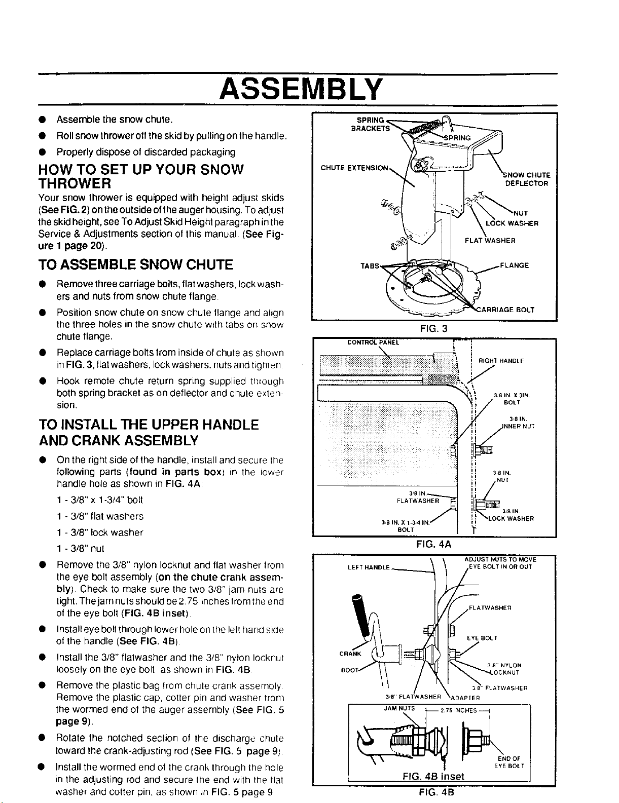
TO ASSEMBLE SNOW CHUTE
• Remove three carriage bolts, flat washers, lock wash-
ers and nuts from snow chute flange.
• Position snow chute on snow chute llange and align
the three holes in the snow chute with tabs on snow
chute flange.
• Replace carriage bolts from inside of chute as shown
in FIG. 3, flat washers, lock washers, nuts and tighter]
• Hook remote chute return spring supplied through
both spring bracket as on deflector and chute exten
sion.
TO INSTALL THE UPPER HANDLE
AND CRANK ASSEMBLY
• On the right side of the handle, install and secure tile
following pads (found in parts boxl in the lower
handle hole as shown in FIG. 4A:
1 - 3/8" x 1-3/4" bolt
1 - 3/8" flat washers
1 - 3/8" lockwasher
1 - 3/8" nut
Remove the 3/8" nylon Iocknut and flat washer from
the eye bolt assembly (on the chute crank assem-
bly). Check to make sure the two 3/8" jam nuts are
tight. The jam nuts should be275 inches from _heend
of the eye bolt (FIG. 4B inset)
Install eye bolt through lower hole on the left hand side
ot the handle (See FIG. 4B)
Install the 3/8" flatwasher and the 3/8" nylon Iocknul
loosely on the eye bolt as shown in FIG. 4B
Remove the plastic bag lrom chute crank assembly
Remove the plastic cap, cotter pin and washer trom
the wormed end of the auger assembly (See FIG. 5
page 9).
Rotate the notched seclion of the discharge chute
toward the crank-adjusting rod (See FIG. 5 page 9;
Install the wormed end of the crank through the hole
in the adjusting rod and secure the end with the tlat
washer and cotter pin, as shown in FIG. 5 page 9
BRACKETS
SPRING _
CHUTE EXTENSION _ #L ......
TABS ., FLANGE
_ARRIAGE BOLT
FIG. 3
CONTROL PANEL _'-'-'!
" " _ : : ." • " " "_'_" _ R GHT HANDLE
• .... l
_ BOLT
/
d
3s8 IN.
CRANK
FLATWAS_
3_8 IN. X 1-3_4 IN.
BOLT
FIG. 4A
3sB"ELATWASHER
JAM NUTS
\
FIG. 4B inset
FIG. 4B
_LOCK WASHER
¥
ADJUST NUTS TO MOVE
.EYE BOLT IN OR OUT
;LAfWASHER
EYE BOLl
38'FLATWASHER
DAPTER
NOW
DEFLECTOR
3 8 IN. X 3IN+
381N.
,_NNER NUT
381N.
38"NYLON
END OF
EYE BOLT
CHUTE
ASSEMBLY
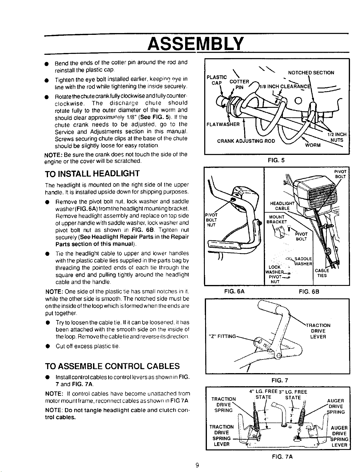
Bend the ends of the cotter pin around the rod and
reinstall the plastic cap.
Tighten the eye bolt installed earlier, keeping eye in
line with the rod while tightening the inside securely
Rotatethe chute crank fully clockwise and tullycounter-
clockwise. The discharge chule should
rotate fully to the outer diameter of the worm and
should clear approximately 1/8" (See FIG. 5). If the
chute crank needs to be adjusted, go to the
Service and Adjustments section in this manual•
Screws securing chute clips at the base of the chute
should be slightly loose for easy rotation
NOTE: Be sure the crank does not touch the side of the
engine or the cover will be scratched.
TO INSTALL HEADLIGHT
The headlight is mounted on the right side of the upper
handle. It is installed upside down for shipping purposes•
Remove the pivot bolt nut, lock washer and saddle
washer (FIG.6A) from the headlight mounting bracket•
Remove headlight assembly and replace ontop side
of upper handle with saddle washer, lock washer and
pivot bolt nut as shown in FIG. 6B Tighten nut
securely (See Headlight Repair Parts in the Repair
Parts section of this manual).
Tie the headlight cable to upper and lower handles
with the plastic cable ties supplied in the parts bag by
threading the pointed ends ot each tie through the
square end and pulling tightly around the headlight
cable and the handle.
NOTE: One side of the plastic tie has small notches in it,
while the other side is smooth. The notched side must be
on the inside of the loop which isformed when the ends are
put together,
• Try to loosen the cable tie. Ifit can be loosened, it has
been attached with the smooth side on the inside ol
the loop• Remove the cable tieand reverse itsdirection
• Cut off excess plastic tie.
PLASTIC\ . NOTCHEDSECTION
CAP COTTER _.
FLATWASHER 1
CRANK ADJUSTING ROD
FIG. 6A FIG. 6B
_1/8INCH CLEARANC
WORM
FIG. 5
BOLT
• C-= SADDLE
• ='_ASH ER
LOCK -
NASHER--_, CABLE
PIVOT--._ TIES
NUT
1/2 INCH
PtVOT;
DRIVE
LEVER
i
TO ASSEMBLE CONTROL CABLES
• Install control cables tocontrol levers as shown in FIG.
7 and FIG. 7A.
NOTE: If control cables have become unattached from
motor mount frame, reconnect cables asshown _nFIG 7A
NOTE: Do not tangle headlight cable and clutch con-
trol cables.
FIG. 7
4" LG. FREE 3" LG. FREE
TRACTION STATE STATE
DRIVE_ _/ _ _L__ /DRIVE
SPRING m,,_)_J_- _! :' A_""_ R PRING
DRIVE I: [_'Q"[J_, ,.¥ _;o\ I DRWE
SPRING _ I___I!I"_"--"_'_,T-S p RING
LEVER ""_ • _ LEVER
: / t iJ AUGER
4,,
FIG. 7A
9
 Loading...