

Craftsman 536886220 Owner’s Manual
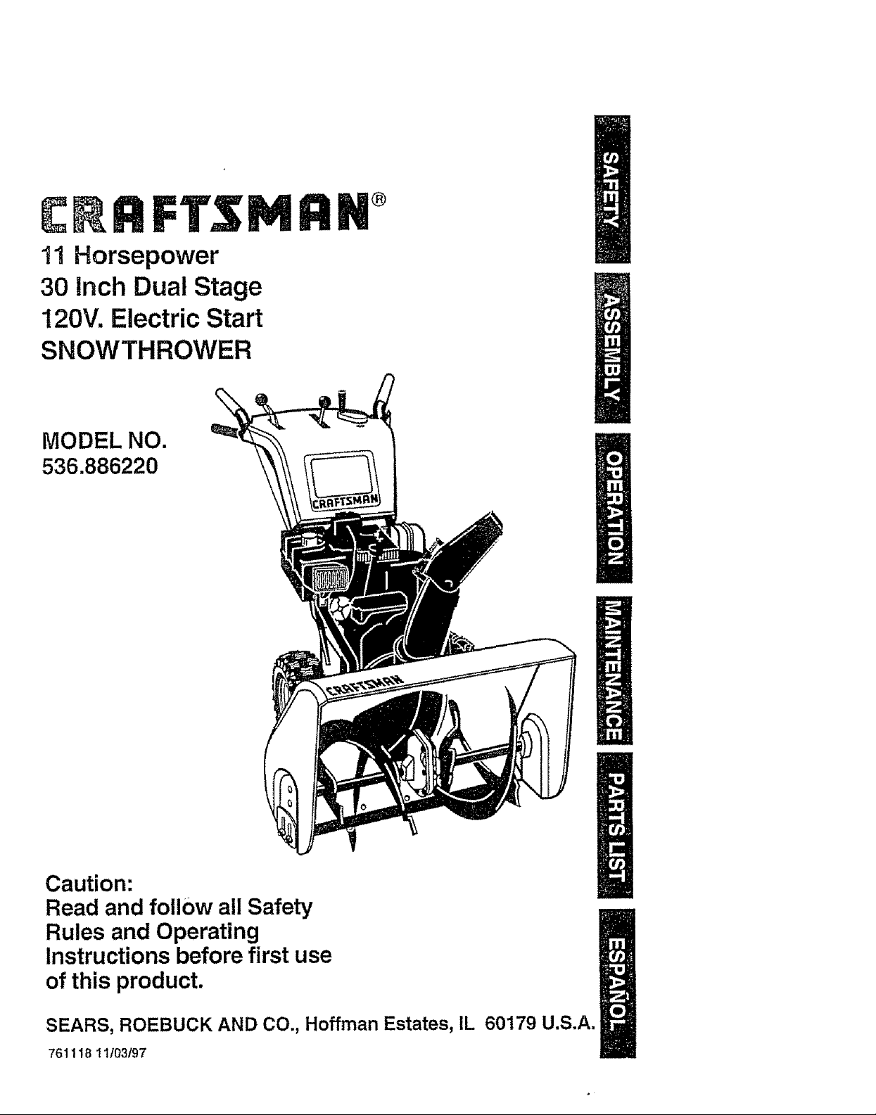
11 Horsepower
30 Inch Dual Stage
120V. Electric Start
SNOWTHROWER
MODEL NO.
536.886220
®
Caution:
Read and follow all Safety
Rules and Operating
Instructions before first use
of this product.
SEARS, ROEBUCK AND CO., Hoffman Estates, IL 60179 U.S.A.
761118 11/03/97
Table of Contents 2
Warranty 2
Safety Rules 2-4
Contents of Shipping Carton 4-5
Assembly 5-9
Operation 10-14
Maintenance 15-17
LIMITED TWO-YEAR WARRANTY ON CRAFTSMAN SNOW THROWER
For two years from the date of purchase, when this Craftsman Snow Thrower is main-
tained, lubricated, and tuned up according to the operating and maintenance instruc-
tions in the owner's manual, Sears will repair, free of charge, any defect in material or
workmanship.
If this Craftsman Snow Thrower is used for commemial or rental purposes, this war-
ranty applies for only 90 days from the date of purchaser
"]his warranty does not cover the following:
• Items which become worn during normal use, such as spark ptugs, drive belts and
shear pins.
• Repairs necessary because of operator abuse or negligence, including bent crank
shafts and the failure to maintain the equipment according to the instructions con-
tained in the owner's manual.
WARRANTY SERVICE 1SAVAILABLE BY RETURNING THE CRAFTSMAN SNOW
THROWER TO THE NEAREST SEARS SERVICE CENTER/DEPARTMENT IN THE
UNITED STATES. THIS WARRANTY APPLIES ONLY WHILE THIS PRODUCT IS IN
USE IN THE UNITED STATES.
This warranty gives you specific legal rights, and you may also have other rights which
may vary from state to state.
Sears, Roebuck and Coo, D817WA0 Hoffman Estates, IL 60179
Service and Adjustments t8-23
Storage 24
Troubleshooting 25
Snow Thrower Repair Parts 26-38
Engine Repair Parts 39-43
Spanish(Espa_ot) 44.70
Parts Ordering/Service _ Back Cover
Look for this symbol to point out important safety precautions, It means---
ATTENTIONlll Become alerttll Your safety is involved,
_ CAUTION: Always disconnect spark
plug wire and place wire where it cannot
contact spark plug to prevent accidental
starting when setting-up, transporting,
adjusting or making repairs_
IMPORTANT: Safety standards require
operator presence controls to minimize the
risk of injury. Your snow thrower is
equipped with such controls. Do not attempt
to defeat the function of the operator
)resence control under any circumstances.
_ California Proposition 65
WARNING=The
engine exhaust from this product
contains chemicals known to the
State of California to cause cancer
birth defects or other reproductive
harm.
TRAINING
1. Read the operator's manual carefully.
Be thoroughly familiar with the controls
and the proper use of the snow thrower.
Know how to stop the snow thrower and
disengage the controls quickly.
2. Never allow children to operate the
snow thrower and keep them away
while it is operating, Never allow adults
to operate the snow thrower without
proper instruction. Do not carry passen-
gers.
3. Keep the area of operation clear of all
persons, particularly small children and
pets.
4. Exercise caution to avoid slipping or
falling, especially when operating in
reverse.
PREPARATION 4.
1. Thoroughly inspect the area where the
snow thrower is to be .used and remove
all doormats, sleds, boards, wires and
other foreign objects. 5.
2 Disengage allclutches before starting
the engine (motor)°
3 Do not operate the snow thrower
without wearing adequate winter outer
garments. Wear footwear that will
Improve footing on slippery surfaces. 6.
4. Handle fuel with care; it is highly
flammable.
(a) Use an approved fuel container.
(b) Never remove fuel tank cap or add
fuel to a running engine or hot 7o
engine.
(c) Fill fue! tank outdoors with extreme
care. Never fill fuel tank indoors.
(d) Replace fuel tank cap securely and
wipe up spiIled fuel. 8_
(e) Never store fuel or snow thrower
with fuel in the tank inside of a
building where fumes may reach
an open flame or spark.
(f) Check fuel supply before each use,
allowing space for expansion as 9.
the heat of the engine (motor) and/
or sun can cause fue! to expand.
5_ Use extension cords and receptacles
as specified by the manufacturer for all 10.
snow throwers with electric drive
motors or electric starting motors,
6. Adjust the snow thrower height to clear
gravel or crushed rock surfaces.
7. Never attempt to make any adjustments
while the engine (motor) is running
(except when specifically recom- 11.
mended by the manufacturer).
8. Let engine (motor) and snow thrower
adjust to outdoor temperatures before
starting to clear snow. 12.
9. Always wear safety glasses or eye
shields during operation or while 13.
performing an adjustment or repair to
protect eyes from foreign objects that
may be thrown from the snow thrower,
OPERATION
1. Do not operate this machine if you are 14,
taking drugs gr other medication which
can cause drowsiness or affect your
ability to operate this machine. 15.
2. Do not use this machine if you are
mentally or physically unable to operate
this machine safely.
3. Do not put hands or feet near or under 16.
rotating parts. Keep clear of the
discharge opening at atl times.
Exercise extreme caution when operat-
ing on or crossing gravel drives, walks,
or roads. Stay alert for hidden hazards
or traffic.
After striking a foreign object, stop the
engine (motor), remove the wire from
the spark plug, disconnect the cord on
electric motors, thoroughly inspect the
snow thrower for any damage, and
repair the damage before restarting and
operating the snow thrower.
If the snow thrower should start to
vibrate abnormally, stop the (motor) and
check immediately for the cause.
Vibration is generally a warning of
troubte.
Stop the engine (motor) whenever you
leave the operating position, before
unclogging the auger/impeller housing or
discharge guide, and when making any
repairs, adjustments, or inspections.
When cleaning, repairing, or inspecting,
make certain the auger/impeller and all
moving parts have stopped. Disconnect
the spark plug wire and keep the wire
away from the plug to prevent accidental
starting.
Take all possible precautions when
leaving the snow thrower unattended.
Disengage the augedimpeller, stop
engine, and remove key,
Do not run the engine indoors, except
when starting the engine and for
transporting the snow thrower in or out
of the building. Open the outside doors;
exhaust fumes are dangerous (contain-
ing CARBON MONOXIDE, an ODOR-
LESS and DEADLY GAS).
Do not clear snow across the face of
slopes. Exercise caution when changing
direction on slopes_ Do not attempt to
clear steep slopes.
Never operate the snow thrower without
proper guards, plates or other safety
protective devices in place_
Never operate the snow thrower near
glass enclosures, automobiles, window
wel_s, drop-offs, and the like without
proper adjustment of the snow discharge
angle. Keep children and pets away,
Do not overload the machine capacity by
attempting to clear snow at too fast a
rate.
Never operate the snow thrower at high
transport speeds on slippery surfaces.
Look behind and use care when
backing.
Never direct discharge at bystanders or
allow anyone in front of the snow
thrower.
17. Disengage power to the auger/impeller
when snow thrower is transportedor
not in use.
18. Use only attachments and accessories
approved by the manufacturer of the
snow thrower (such as tire chains,
electric start kits, etc)o
19. Never operate the snow thrower
without good visibility or light. Always
be sure of your footing, and keep a firm
hold on the handles° Walk; never run.
MAINTENANCE AND STORAGE
1. Check shear bolts and other bolts
frequently for proper tightness to be
sure the snow thrower is in safe
working condition_
2. Never store the snow thrower with fuel
in the fuel tank inside a building where
ignition sources are present such as
hot water and space heaters, clothes
dryers, and the like. Allow the engine
to cool before storing in any enclosure.
3. Always refer to operator's manual
instructions for important details it the
snow thrower is to be stored for an
extended pedod.
4. Maintain or replace safety and instruc-
tion labels, as necessary.
5. Run the snow thrower a few minutes
after throwing snow to prevent freeze-
up of the auger/impeller.
Z_ WARNING" This snow thrower is for
use on sidewalks, driveways and other
ground level surfaces.
Caution should be exercised while using on
steep sloping surfaces. DO NOT USE
SNOW THROWER ON SURFACES
ABOVE GROUND LEVEL such as roofs of
residences, garages, porches or other such
structures or buildings.
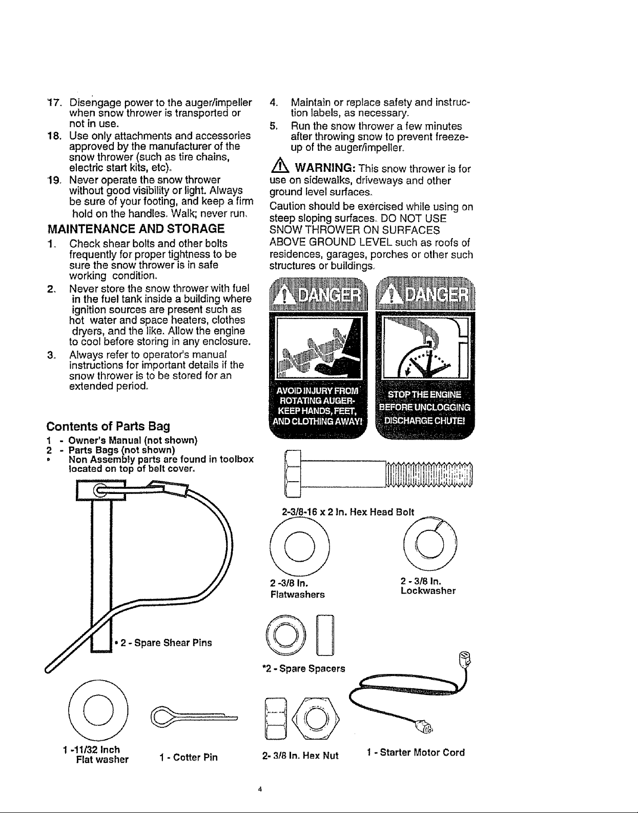
Contents of Parts Bag
Parts Bags (not shown)
- Owner's Manual (not shown)
Non Assembly parts are found in toolbox
located on top of belt cover°
2-3/8-16 x 2 In, Hex Head Bolt
2 -318In. 2 - 318In.
Flatwashers Lockwasher
©D
*2- Spare Spacers
1 -11/32 Inch
Flat washer I - Cotter Pin
2- 318In. Hex Nut
1 - Starter Motor Cord
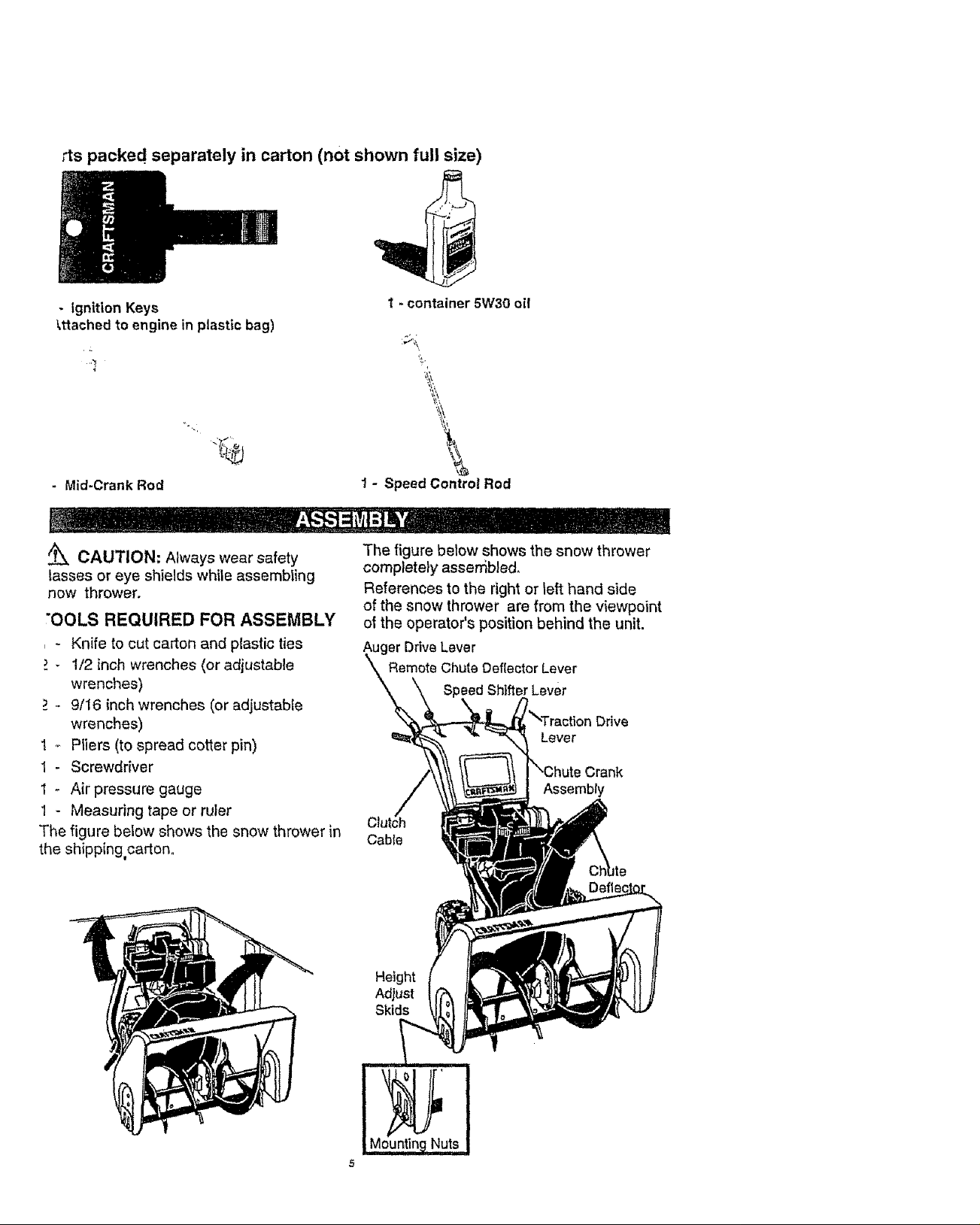
rts packed separately in carton (not shown full size)
- Ignition Keys
_ttached to engine in plastic bag)
-'7
- Mid-Crank Rod
CAUTION: Always wear safety
lasses or eye shields while assembling
now thrower.
"OOLS REQUIRED FOR ASSEMBLY
- Knife to cut carton and plastic ties
- 1/2 inch wrenches (or adjustable
wrenches)
._,- 9/16 inch wrenches (or adjustable
wrenches)
1 _ Pliers (to spread cotter pin)
1- Screwdriver
1 - Air pressure gauge
1 - Measuring tape or ruler
The figure below shows the snow thrower in
the shipping,carton.
I - container 5W30 oil
1 - Speed Contro! Rod
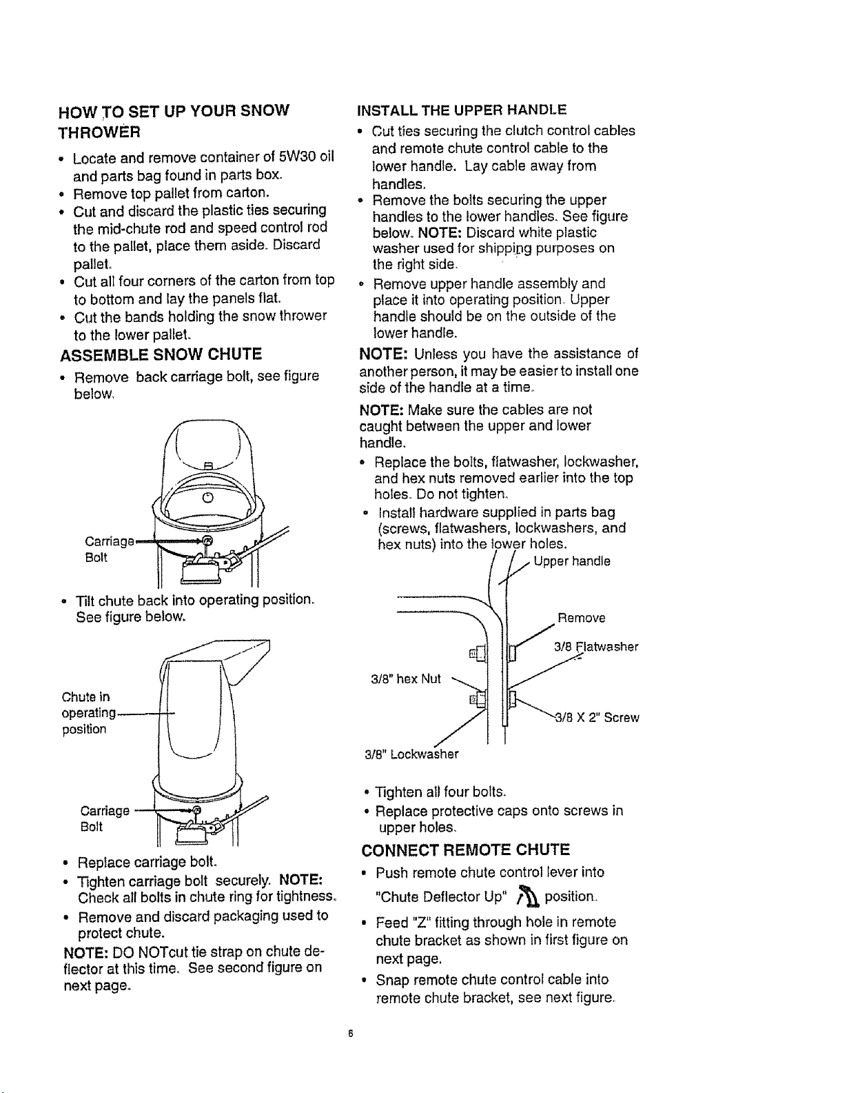
The figure below shows the snow thrower
completely assembled.
References to the right or left hand side
of the snow thrower are from the viewpoint
ot the operator's position behind the unit.
er Drive Lever
Remote Chute Deflector Lever
Speed ShifterLever
rive
Lever
Assembly
CabIe
5
Height
Adjust
Skids
o
HOW T ° SET UP YOUR SNOW
THROWER
• Locate and remove container of 5W30 oil
and parts bag found in parts box.
• Remove top pallet from carton.
• Cut and discard the plastic ties securing
the mid-chute rod and speed control rod
to the pallet, place them aside. Discard
pallet.
• Cut all four corners of the carton from top
to bottom and lay the panels flat.
• Cut the bands holding the snow thrower
to the lower pallet.
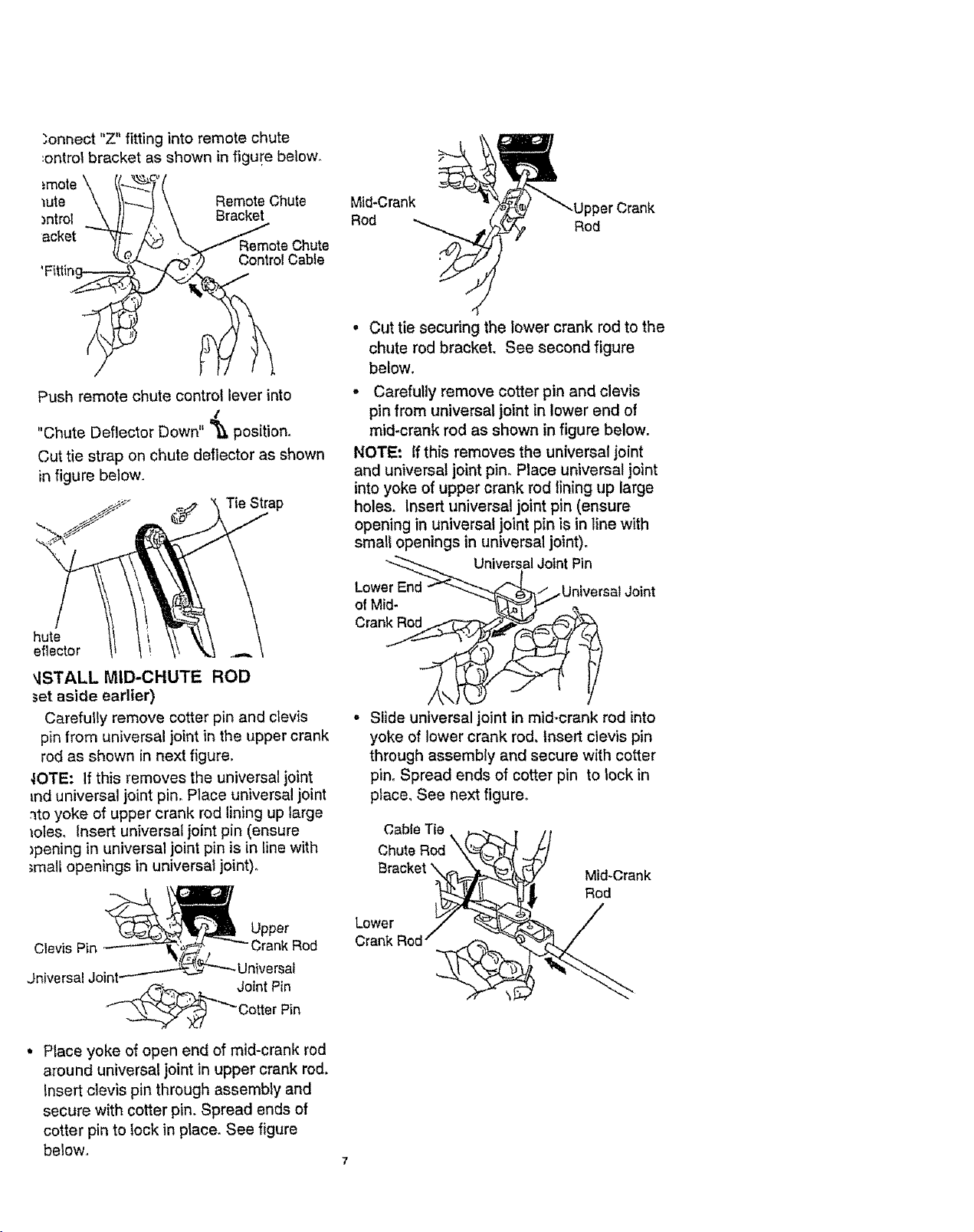
ASSEMBLE SNOW CHUTE
• Remove back carriage bolt, see figure
below,
Carria
Bert
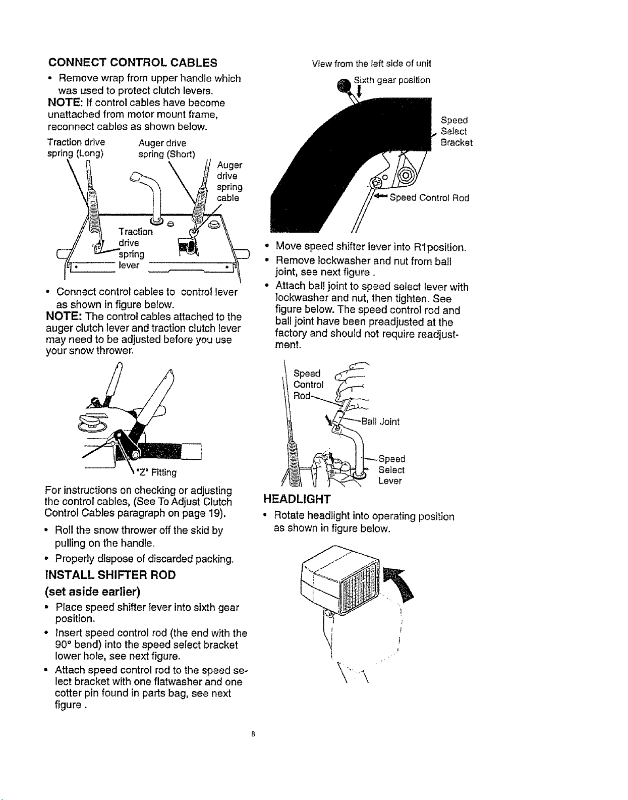
INSTALL THE UPPER HANDLE
• Cut ties securing the clutch control cables
and remote chute control cable to the
lower handle. Lay cable away from
handles.
• Remove the bolts securing the upper
handles to the lower handles. See figure
below. NOTE: Discard white plastic
washer used for shipp!pg purposes on
the right side.
o Remove upper handle assembly and
place it into operating position° Upper
handle should be on the outside of the
lower handle.
NOTE: Unless you have the assistance of
another person, it may be easier to install one
side of the handle at a time,
NOTE: Make sure the cables are not
caught between the upper and lower
handle.
• Replace the boIts, ffatwasher, Iockwasher,
and hex nuts removed earlier into the top
holes° Do not tighten°
• Install hardware supplied in parts bag
(screws, flatwashers, iockwashers, and
hex nuts) into the lower holes.
/ //../Upper handle
• Tilt chute back into operating position.
See figure below,
Chute in
operating_
position
Carriage
Bolt
• Replace carnage bolt.
• Tighten carriage bolt securely. NOTE:
Check all bolts in chute ring for tightness.
° Remove and discard packaging used to
protect chute.
NOTE: DO NOTcut tie strap on chute de-
flector at this time, See second figure on
next page.
--i
__latwasher
_""_3/8 X 2" Screw
3/8" hex Nu__
3/8" Lockwasher
• Tighten all four bolts.
• Replace protective caps onto screws in
upper holes.
CONNECT REMOTE CHUTE
• Push remote chute control lever into
"Chute Deflector Up" f_ position,
• Feed "Z" fitting through hole in remote
chute bracket as shown in first figure on
next page,
• Snap remote chute control cable into
remote chute bracket, see next figure,
Remove
_onnect "Z" fitting into remote chute
'.ontrol bracket as shown in figure below.
:mote
_ute Remote Chute
_ntrol Bracket
acket
JmoteChute
Control Cable
Push remote chute control lever into
,it
"Chute Deflector Down" '_ position.
Cut tie strap on chute deflector as shown
in figure below.
Mid.Crank
Rod
Rod
• Cut tie securing the lower crank rod to the
chute rod bracket. See second figure
below.
- Carefully remove cotter pin and clevis
pin from universal joint in lower end of
mid-crank rod as shown in figure below.
NOTE: Ifthis removes the universal joint
and universal joint pin° Place universal joint
into yoke of upper crank rod lining up large
holes° Insert universal joint pin (ensure
opening in universal joint pin is in line with
small openings in universal joint).
---.__ Universal Joint Pin
Lower End_"_.._-_ ....j UniversalJoint
of Mid- "1/_ _
hute
eflector
',ISTALL MID-CHUTE ROD
;et aside earlier)
Carefully remove cotter pin and clevis
pin from universal joint in the upper crank
rod as shown in next figure.
_OTE: If this removes the universal joint
_nd universal joint pin, Place universal joint
._toyoke of upper crank rod lining up large
iotes, Insert universal joint pin (ensure
_pening in universal joint pin is in line with
;mall openings in universal joint).
_' Upper
C,evis Pin------'-'_/ -"'Crank Rod
Jniversal Joint_'_'''_ Universal
_._ Joint Pin
-'_ Cotter Pin
• Place yoke of open end of mid-crank rod
around universal joint in upper crank rod.
Insert clevis pin through assembly and
secure with cotter pin. Spread ends of
cotter pin to lock in place, See figure
below,
Cran_
a
Slide universal joint in mid-crank rod into
yoke of lower crank rod, insert clevis pin
through assembly and secure with cotter
pin. Spread ends of cotter pin to lock in
place, See next figure_
Cable Tie
Chute
Bracket
Mid-Crank
Rod
Lower
CONNECTCONTROLCABLES
• Removewrapfrom upper handle which
was used to protect clutch levers.
NOTE: If control cables have become
unattached from motor mount frame,
reconnect cables as shown below_
Traction drive Auger drive
spring (Long) spring (Short)
Auger
drive
spring
cable
I lever
• Connect control cables to control lever
as shown in figure below.
NOTE: The control cables attached to the
auger clutch lever and traction clutch lever
may need to be adjusted before you use
your snow thrower
View from the left side of unit
gear position
Control Rod
o
Move speed shifter lever into R 1position,
Remove Iockwasher and nut from ball
joint, see next figure
Attach ball joint to speed select lever with
lock'washer and nut, then tighten. See
figure below. The speed control rod and
ball joint have been preadjusted at the
factory and should not require readjust-
ment.
Speed
Select
Bracket
Z" Fitting
For instructions on checking or adjusting
the control cables, (See To Adjust Clutch
Control Cables paragraph on page 19).
• Roll the snow thrower off the skid by
pulling on the handle
, Properly dispose of discarded packing.
INSTALL SHIFTER ROD
(set aside earlier)
• Place speed shifter Iever into sixth gear
position.
• Insert speed control rod (the end with the
90° bend) into the speed select bracket
lower hole, see next figure
• Attach speed control rod to the speed se-
lect bracket with one flatwasher and one
cotter pin found in parts bag, see next
figure _
Speed
Control T..m--_
Ball Joint
# _ 1I _',-_'-m'" Lever
HEADLIGHT
• Rotate headlight into operating position
as shown in figure below.
J CHECKLIST
Before you operate your new snow thrower,
to ensure that you receive the best perfor-
mance and satisfaction from this quality
product, please review the following
checklist:
J All assembly instructions have been
completed.
,,I The discharge chute rotates freely.
While learning how to use your snow
thrower, pay extra attention to the following
important items:
/J" Engine oil is at proper level°
,/# Make sure gas tank is filled properly
with clean, fresh, unleaded gasoline°
#'/ Become familiar with all controls-their
location and function. Operate controls
before starting engine.
,.I No remaining loose parts in carton.
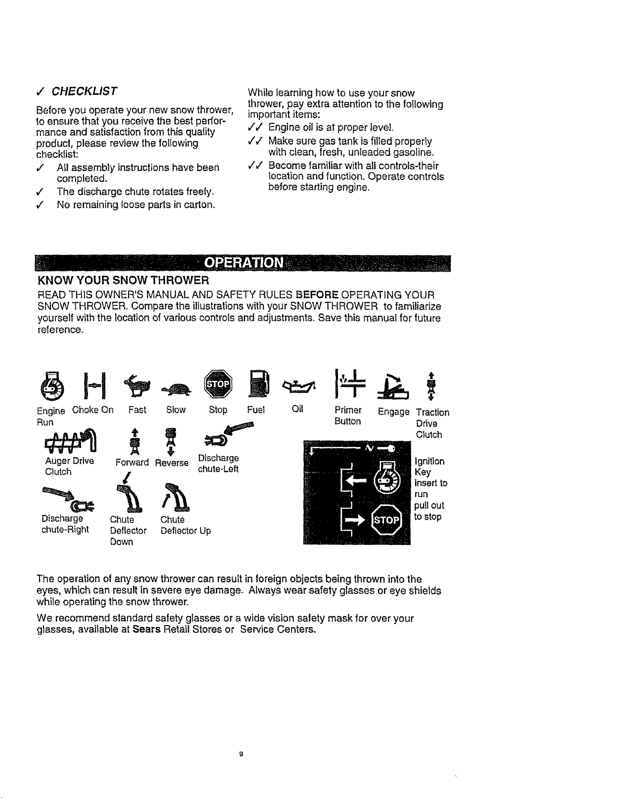
KNOW YOUR SNOW THROWER
READ THIS OWNER'S MANUAL AND SAFETY RULES BEFORE OPERATING YOUR
SNOW THROWER. Compare the illustrations with your SNOW THROWER to familiarize
yourself with the location of various controls and adjustments. Save this manual for future
reference_
Engine Choke On Fast Slow
Run
Stop Fuel
Oil Primer Engage Traction
Button Drive
Clutch
Auger Drive Forward Reverse
Clutch
_ chute-Left Key
_ _ run
Discharge
chute-Right
Chute Chute
Deflector Deflector Up
Discharge Ignition
insert to
)ull out
Down
The operation of any snow thrower can result in foreign objects being thrown into the
eyes, which can result in severe eye damage° Always wear safety glasses or eye shields
while operating the snow thrower°
We recommend standard safety glasses or a wide vision safety mask for over your
glasses, available at Sears Retail Stores or Service Centers.
Ignition
Control
Remote Chute Control Lever
Auger Drive
Electric Starter Button
Aug
Speed Shifter Lever .
MranK Assembly
\
Lever
Chute Deflector
Chute
Height Adjust
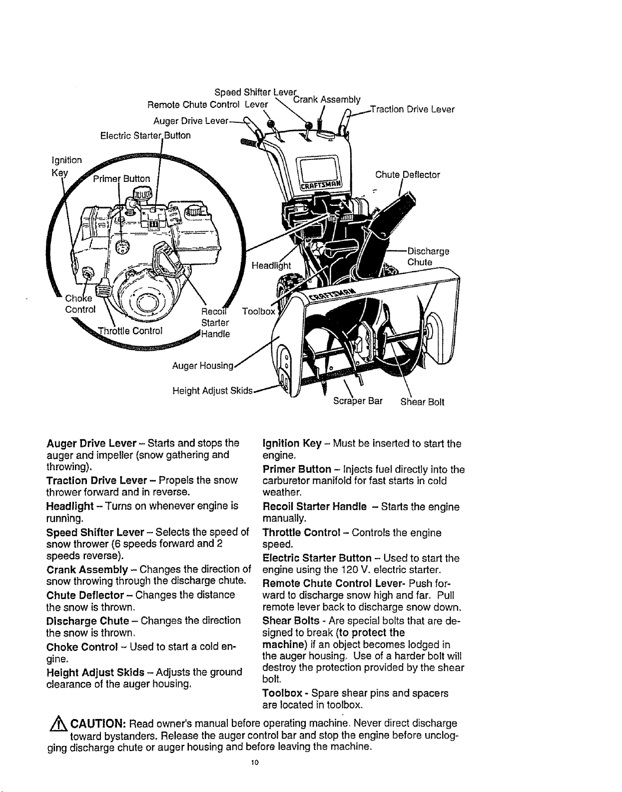
Auger Drive Lever - Starts and stops the
auger and impeller (snow gathering and
throwing),
Traction Drive Lever - Propels the snow
thrower forward and in reverse.
Headlight - Turns on whenever engine is
running,
Speed Shifter Lever - Selects the speed of
snow thrower (6 speeds forward and 2
speeds reverse).
Crank Assembly - Changes the direction of
snow throwing through the discharge chute.
Chute Deflector - Changes the distance
the snow is thrown,
Discharge Chute - Changes the direction
the snow is thrown.
Choke Control ,- Used to start a cold en-
gine.
Height Adjust Skids - Adjusts the ground
clearance of the auger housing_
_erBar Shear Bolt
\
Ignition Key - Must be inserted to start the
engine°
Primer Button - Injects fuel directly into the
carburetor manifold for fast starts in cold
weather,
Recoil Starter Handle - Starts the engine
manually°
Throttle Control - Controls the engine
speed,
Electric Starter Button - Used to start the
engine using the 120 V. electric starter°
Remote Chute Control Lever- Push for-
ward to discharge snow high and far_ Pull
remote lever back to discharge snow down,
Shear Bolts - Are special bolts that are de-
signed to break (to protect the
machine) if an object becomes lodged in
the auger housing. Use of a harder bolt will
destroy the protection provided by the shear
bolto
Toolbox - Spare shear pins and spacers
are located in toolbox.
//_ CAUTION: Read owner's manual before operating machine, Never direct discharge
toward bystanders. Release the auger control bar and stop the engine before unclog-
ging discharge chute or auger housing and before leaving the machine.
1o
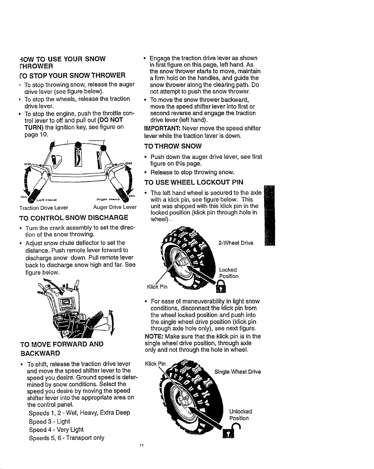
-IOW TO USE YOUR SNOW
tHROWER
rO STOP YOUR SNOW THROWER
, To stop throwing snow, release the auger
drive lever (see figure below).
, To stop the wheels, release the traction
drive lever.
• To stop the engine, push the throttle con-
trol lever to off and pull out (DO NOT
TURN) the ignition key, see figure on
page 10.
All;lht Plan_
Auger Drive Lever
TO CONTROLSNOW DISCHARGE
o
Turn the crank assembly to set the direc-
tion of the snow throwing.
Adjust snow chute deflector to set the
distance. Push remote lever forward to
discharge snow down° Pull remote lever
back to discharge snow high and far. See
figure below,
• Engage the traction drive lever as shown
in first figure on this page, left hand. As
the snow thrower starts to move, maintain
a firm hold on the handles, and guide the
snow thrower along the clearing path. Do
not attempt to push the snow thrower,
• To move the snow thrower backward,
move the speed shifter lever into first or
second reverse and engage the traction
drive lever (left hand).
IMPORTANT: Never move the speed shifter
lever while the traction lever is down.
TO THROW SNOW
• Push down the auger drive lever, see first
figure on this page.
• Release to stop throwing snow.
TO USEWHEEL LOCKOUT PIN
, The left hand wheel is secured to the axle
with a klick pin, see figure below. This
unit was shipped with this klick pin in the
locked position (klick pin through hole in
wheel).
2-Wheel Drive
Locked
Position
TO MOVE FORWARD AND
BACKWARD
To shift, release the traction drive lever
and move the speed shifter lever to the
speed you desire'. Ground speed is deter-
mined by snow conditions. Select the
speed you desire by moving the speed
shifter lever into the appropriate area on
the control panel.
Speeds 1, 2 - Wet, Heavy, Extra Deep
Speed 3 - Light
Speed 4 - Very Light
Speeds 5, 6 - Transport only
• For ease of maneuverability in light snow
conditions, disconnect the klick pin from
the wheel locked position and push into
the single wheel drive position (klick pin
through axle hole only), see next figure.
NOTE: Make sure that the klick pin is in the
single wheel drive position, through axle
only and not through the hole in wheel.
Klick Pin
Single Wheel Drive
Unlocked
Position
BEFORE STARTING THE ENGINE
. If the snow thrower must be moved with-
out the aid of the engine, it is easier to pull
the snow thrower by the handles rather
than pushing.
° Before you service or start the engine, fa-
miliarize yourself with the snow thrower.
Be sure you understand the function and
location of all controls.
NOTE: Check tension of c_utch cables be-
fore starting the engine (See To Adjust The
Control Cables paragraph on page 19).
o Be sure that all fasteners are tight.
• Make sure the height adjust skids are
properly adjusted (See To Adjust Skid
Height paragraph on page 18)_
• Check tire pressure (14 pounds). See
side of tire for maximum inflation. Do not
exceed listed maximum pressure.
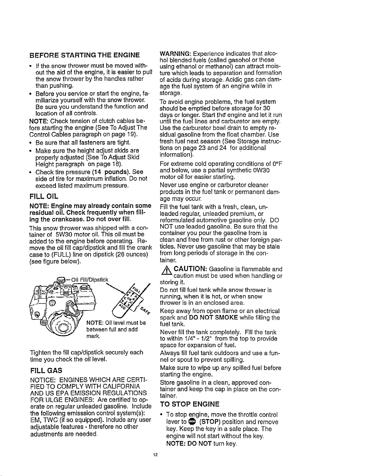
FILL OIL
NOTE: Engine may already contain some
residual oil. Check frequently when fill-
ing the crankcase, Do not over fill,
This snow thrower was shipped with a con-
tainer of 5W30 motor oil. This oil must be
added to the engine before operating_ Re-
move the oi! fill cap/dipstick and fill the crank
case to (FULL) line on dipstick (26 ounces)
(see figure below).
Fill/Dipstick
NOTE: Oit level must be
between full and add
mark.
Tighten the fill cap/dipstick securely each
time you check the oil leve!.
FILL GAS
NOTICE: ENGINES WHICH ARE CERTI-
FIED TO COMPLY WITH CALIFORNIA
AND US EPA EMISSION REGULATIONS
FOR ULGE ENGINES: Are certified to op-
erate on regular unleaded gasoline. Include
the following emisssion control system(s):
EM, TWC (if so equipped). Include any user
adjustable features - therefore no other
adustments are needed.
WARNING: Experience indicates that alco-
hol blended fuels (called gasohol or those
using ethanol or methanol) can attract mois-
ture which leads to separation and formation
of acids during storage,, Acidic gas can dam-
age the fuel system of an engine while in
storage,
To avoid engine problems, the fuel system
should be emptied before storage for 30
days or longer. Start the" engine and let it run
until the fuel lines and carburetor are empty.
Use the carburetor bowl drain to empty re-
sidual gasoline from the float chamber, Use
fresh fuel next season (See Storage instruc-
tions on page 23 and 24 for additional
information).
For extreme cold operating conditions of 0°F
and below, use a partial synthetic 0W30
motor oit for easier starting.
Never use engine or carburetor cleaner
products in the fuel tank or permanent dam-
age may occur,
Fill the fuel tank with a fresh, clean, un-
leaded regular, unleaded premium, or
reformulated automotive gasoline only, DO
NOT use leaded gasoline. Be sure that the
container you pour the gasoline from is
clean and free from rust or other foreign par-
ticles. Never use gasoline that may be stale
from long periods of storage in the con-
tainer.
_ CAUTION: Gasoline is flammable and
caution must be used when handling or
storing it,
Do not fill fuel tank while snow thrower is
running, when it is hot, or when snow
thrower is in an enclosed area,
Keep away from open flame or an electrical
spark and DO NOT SMOKE while filling the
fuel tank.
Never fill the tank completely. Fill the tank
to within 1/4" - 1/2" from the top to provide
space for expansion of fuel.
Always fill fuel tank outdoors and use a fun-
nel or spout to prevent spilling.
Make sure to wipe up any spilled fuel before
starting the engine.
Store gasoline in a clean, approved con-
tainer and keep the cap in place on the con-
tainero
TO STOP ENGINE
To stop engine, move the throttle control
lever to _ (STOP) position and remove
key. Keep the-key in a safe place. The
engine will not start without the key.
NOTE: DO NOT turn key.
12
3 START ENGINE (Electric Starter)
,_sure that the engine has sufficient oil
_e snow thrower engine is equipped with a
_.0volt A,C. electric starter and recoil
artero Before starting the engine, be cer-
in that you have read the following infor-
mation:
_ CAUTION: This starter is equipped
with a three-wire power cord and plug
nd is designed to operate on 120 volt AC
ousehoid current, it must be properly
rounded at all times to avoid the possibility
f electrical shock which may be injurious to
peraton Follow al! instructions carefully as
et forth in the "To Start Engine" section.
)etermine that your house wiring is a three-
cite grounded system° Ask a licensed elec-
t!clan if you are not sure. if your house
vire system is not a three-wire system, do
_ot use this electric starter under any condi-
ions. if your system is grounded and a
brae-hole receptacle is not available at the
_oint your starter will normally be used, one
_hould be installed by a licensed electrician.
_hen connecting 120 volt AC power cord,
_tways connect the cord to the switch box
on the engine first, then plug the other end
into the three-hole grounded receptacle.
When disconnecting power cord, always
unplug the end in the three-hole grounded
receptacle first.
COLD START
. Be sure the auger drive and traction drive
levers are in the disengaged (released)
position,
, Move the throttle control to '_ (FAST)
position, See figure on page 10.
• Remove the keys from the plastic bag.
Insert one key into the ignition slot. Be
sure it snaps into place, DO NOT TURN
KEY. Keep the second key in a safe
place.
• Rotate the choke knob to H choke ON
position. See figure on page 10.
• Connect the power cord to the switch box
on the engine_
• Plug the other end of the power cord into
a three-hole, grour_ded 120 volt ArC.
receptacle.
, Push the primer button while covering the
vent hole as follows: (Remove finger from
primer button between primes). See
figure on page t0 for location.
Do not prime it temperature is above
50°F.
Two times if temperature is 50°F to 15°F.
Four times if temperature is below 15°Fo
, Push down on the starter button until the
engine starts. Do not crank for more than
t0 seconds at a time. This electric starter
is thermally protected. If overheated it will
stop automatically and can be restarted
only when it has cooled to a safe
temperature (a wait of about 5 to 10
minutes is required).
• When the engine starts, release the
starter button and move choke lever to "1/
2 choke" position. When engine runs
smoothly, move choke lever to "No
Choke" Position_
• Disconnect the power cord from the
receptacle first and then from the switch
box on engine.
NOTE: Allow the engine to warm up for
several minutes before blowing snow in
temperatures below 0°Fo
• Run the engine at full throttle "f_ (FAST)
when throwing snow.
TO START ENGINE (Recoil Starter)
Be sure that the engine has sufficient oil.
The snow thrower engine is equipped with a
recoil starter. Before starting the engine, be
certain that you have read the following in-
formation:
COLD START
° Be sure the auger drive and traction drive
levers are in the disengaged (released)
position.
• Move the throttle control to "_ (FAST)
position. See figure on page 10 for loca-
tion,
° Remove the keys from the plastic bag. In-
sert one key into the ignition slot. Be sure
it snaps into place. DO NOT TURN KEY.
Keep the second key in a safe place.
• Rotate the choke knob to H choke
ON position. See figure on page 10.
• Push the primer button, see figure on
page 10, while covering the vent hole as
follows: (Remove finger from primer but-
ton between primes).
Do not prime if temperature is above
50oE
Two times if temperature is 50°F to 15°E
Four times if temperature is below 15°E
• Pull the recoil starter handle rapidly. Do
not allow the handle to snap back, but al-
low it to rewind slowly while keeping a
firm hold on the starter handle.
13
., As engine starts warms up move choke
lever to "1/2 choke" position. When engine
runs smoothly, move choke lever to "No
Choke" Position
NOTE: Allow the engine to warm up for
several minutes before blowing snow in tem-
peratures below 0°F.
• Run the engine at full throttle _ (FAST)
when throwing snow.
WARM START
If restarting a warm engine after a short
shutdown, leave choke at (OFF) and do not
push the primer button. If the engine fails to
start, follow the Cold Start instructions
above.
FROZEN RECOIL STARTER
If the starter is frozen and will not turn
engine:
, Pull as much rope out of the starter as
possible.
• Release the starter handle and let it snap
back against the starter.
If the starter still fails to turn engine, repeat
the two previous steps until the starter en.
gages, Then continue with the directions for
cold start,
To help prevent possible freeze-up of recoil
starter and engine controls, proceed as fol-
lows after each snow removal job.
• With the engine running, pull the starter
rope hard with a continuous full arm
stroke three or four times. Pulling of
starter rope will produce a loud clattering
sound. This is not harmful to the engine or
starter.
° With the engine not running, wipe al!
snow and moisture from the carburetor
cover in area of control levers. Also move
throttle control, choke control, and starter
handle several times.
Z_ CAUTION: Never run engine indoors
or in enclosed, poorly ventilated areas.
Engine exhaust contains carbon monoxide,
an odorless and deadly gas. Keep hands,
feet, hair and loose clothing away from any
moving parts on engine and snow thrower_
WARNING: Temperature of muffler and
nearby areas may exceed 150 ° F. Avoid
these areas.
DO NOT allow children or young teenagers
to operate or be near snow thrower while it
is operating°
/_ CAUTION: Do no attempt to remove
any item that may become lodged in
auger without taking the following precau-
tions:
• Release auger drive and traction drive
levers°
° Move throttle lever to stop position.
• Remove (DO NOT TURN) ignition key.
• Disconnect spark,prug wire.
• Do not place your hands in the auger or
discharge chute. Use a pry bar.
SNOW THROWING TIPS
• For maximum snow thrower efficiency in
removing snow, adjust ground speed,
NEVER the throttle° Go slower in deep,
freezing, or wet snow. If the wheels slip,
reduce forward speed. The engine is de-
signed to deliver maximum performance
at full throttle and should be run at this
power setting at all times. Most efficient
snow blowing is accomplished when the
snow isremoved immediately after it falls.
• Forcomplete snow removal, slightly over-
lap each path previously taken. Use more
overlap in deep snow to prevent overload-
ing,
• The snow should be discharged down
wind whenever possible. In windy condi-
tions, lower the chute deflector to direct
discharged snow close to the ground,
where it is less likely to blow into un-
wanted areas.
• For normal usage, set the skids so that
the scraper bar is 1/8" above the skids.
For extremely hard-packed snow sur-
faces, adjust the skids upward so that the
scraper bar touches the ground°
° On gravel or crushed rock surfaces, set
the skids at t-1/4" below the scraper bar
(See To Adjust Skids Height paragraph on
page I8)_ Stones and gravel must not be
picked up and thrown by the machine.
° After the snow throwing job has been
completed, allow the engine to idle for a
few minutes, which will melt snow and ac-
cumulated ice off the engine.
• Clean the snow thrower thoroughly after
each use.
• Remove ice and snow accumulation and
all debris from the entire snow thrower,
and flush with water (if possible) to re-
move all salt or other chemicals. Wipe
,snow thrower dry_
_4
 Loading...