

Craftsman 536886190 Owner’s Manual
CRRFTSMRW
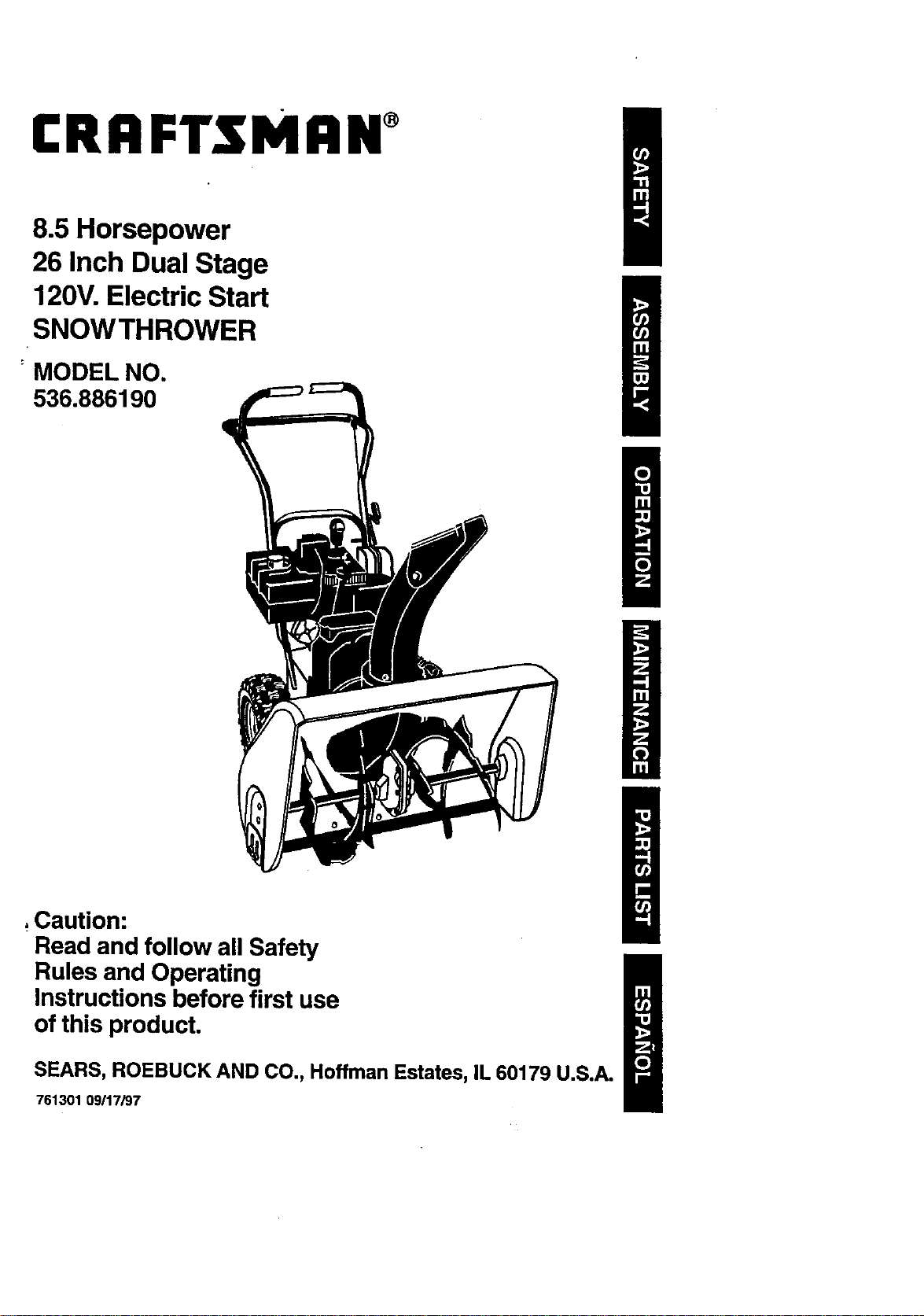
8.5 Horsepower
26 Inch Dual Stage
120V. Electric Start
SNOWTHROWER
MODEL NO.
536.886190
,Caution:
Read and follow all Safety
Rules and Operating
Instructions before first use
of this product.
SEARS, ROEBUCK AND CO., Hoffman Estates, IL 60179 U.S.A.
761301 09117/97
Table of Contents 2 Service and Adjustments 17,21
Warranty 2 Storage 22
Safety Rules 2-4 Troubleshooting 23
Contents ofShipping Carton 4-5 Repair Parts 24-32
Assembly 5-8 Engine Repair Parts 33-37
Operation 8-14 Spanish(EspaSol) 38-63
Maintenance 14-16 Parts Ordering/Service Back Cover
LIMITED TWO-YEAR WARRANTY ON CRAFTSMAN SNOW THROWER
For two years from the date of purchase, when this Craftsman Snow Thrower is maintained,
lubricated, and tuned up according to the operating and maintenance instructions in the
owner'smanual, Craftsman will repair, free of charge, any defect in material or workmanship.
If this Craftsman Snow Thrower is used for commercial or rental purposes, this warranty
applies for only 90 days from the date of purchase.
This warranty does not cover the following:
• Items which become worn during normal use, such as spark plugs, ddve belts and
• shear pins.
• Repairs necessary because of operator abuse or negligence, includingbent crank
shafts and the failure to maintainthe equipment accordingto the instructionscon-
tained in the owner's manual.
WARRANTY SERVICE IS AVAILABLE BY RETURNING THE CRAFTSMAN SNOW
THROWER TO THE NEAREST CRAFTSMAN SERVICE CENTER/DEPARTMENT IN THE
UNITED _TJ_TES. THIS WARRANTY APPLIES ONLY WHILE THIS PRODUCT IS IN USE
IN THE UNITED STATES. ,
This warranty gives you specific legal dghts, and you may also have other rightswhich may
vary from state to state.
Sears, Roebuck and Co,, D817WA, Hoffman Estates, IL 60179
/_ Look for this symbol to point out important safety precautions. It means--
,/_ CAUTION: Always disconnect spark
plug wire and place wire where it cannot
contact spark plug to prevent accidental
starting when setting-up, transporting,
adjustingor making repairs.
IMPORTANT: Safety standards require
operator presence controlsto minimize the
risk of injury.Your snow thrower is
equipped with such controls.Do not attempt
to defeat the function of the operator
presence controlunder any circumstances.
ATTENTIONI!! Become alert!l! Your safety is involved.
TRAINING
1. "Read the operators manual carefully.
Be thoroughlyfamiliar with the controls
and the proper use of the snow thrower.
Know bow to stop the snow thrower and
disengage the controlsquickly.
2. Never allow children to operate the snow
thrower and keep them away while it is
operating. Never allow adults to operate
the snow thrower without proper instruc-
tion. Do not carry passengers.
3. Keep the area of operation clear of all
persons, particularly small children and
pets.
t_ California Proposition 65
WARNING:The
engine exhaust from thisproduct
containschemicals known to the
State of Californiato cause cancer
birthdefects or other reproductive
harm.
4. Exercisecaution to avoidslipping or
falling, especially when operating in
reverse.
PREPARATION
,
Thoroughlyinspect the area where the
snow thrower isto be used and remove
all doormats, sleds, boards, wires and
other foreign objects_
2. Disengageallclutchesbeforestartihg
theengine(motor).
3. Donotoperatethesnowthrower
withoutwearingadequatewinterouter 5.
garments.Wearfootwearthatwill
irnpmvefootingonslipperysurfaces.
4. Handlefuelwithcare;itishighly
flammable.
(a) Useanapprovedfuel container.
(b) Never remove fuel tank cap or add 6.
fuel to a running engine or hot
engine.
(c) Fill fuel tank outdoors with
extreme care. Never fill fuel tank
indoors. 7.
(d) Replace fuel tank cap securely
and wipe up spilledfuel.
(e) Never store fuel or snowthrower
with fuel in the tank inside of a
building where fumes may reach 8.
an open flame or spark.
(f) Check fuel supply before each
use, allowing space for expansion
as the heat of the engine (motor)
and/or suncan cause fuel to
expand. 9.
5. Use extension cords and receptacles
as specified by the manufacturer for all
snow throwers with electric drive
motorsor electric starting motors. 10.
6. Adjust the snow thrower height to clear
gravel or crushed rock surfaces.
7. Never attempt to make any adjust-
ments while the engine (motor) is
running (except when specifically
recommended by the manufacturer). 11.
8. Let engine (motor) and snow thrower
adjust to outdoor temperatures before
starting to clear snow.
9. Always wear safety glasses or eye 12.
shields during operation or while
performing an adjustment or repair to
protect eyes from foreign objects that 13.
may be thrown from the snow thrower.
OPERATION
1. Do not operate this machine ifyou are
taking drugs or other medication which
can cause drowsiness or affect your 14.
ability to operate this machine.
2. Do not use this machine if you are
mentally or physically unableto 15.
operate this machine safely.
3. Do not put hands or feet near or under
rotating parts. Keep clear of the
dischargu opening atall times. 16.
4. Exercise extreme caution when oper-
ating on or crossinggravel drives,
walks, or roads. Stay alert for hidden
hazards or traffic.
After strikinga foreign object, stop the
engine (motor), remove the wire from
the spark plug, disconnect the cord on
electric motors, thoroughly inspect the
snow thrower for any damage and
repa rthe damage before restarting
operating the snow thrower.
If the snow thrower shouldstart to
vibrate abnormally, stop the (motor)
end check immediately for the cause.
Vibration is generally a warning of
trouble.
Stop the engine (motor) whenever you
leave the operating position,before
unclogging the auger/impeller housing
or discharge guide, and when making
any repairs, adjustments, or inspec-
tions.
When cleaning, repairing, or inspecting,
make certain the auger/impeller and all
moving parts have stopped. Disconnect
the spark plug wire and keep the wire
away from the plug to prevent acciden-
tal starting.
Take all possible precautions when
leaving the snow thrower unattended.
Disengage the auger/impeller, stop
engine, and remove key.
Do not runthe engine indoors, except
when startingthe engine and for
transportingthe snow thrower in or out
of the building.Open the outside doors;
exhaust fumes are dangerous (contain-
ing CARBON MONOXIDE, an ODOR-
LESS and DEADLY GAS).
Do not clear snow across the face of
slopes. Exercise caution when changing
direction on slopes. Do not attempt to
clear steep slopes.
Never operate the snow thrower without
proper guards, plates or other safety
protective devices inplace.
Never operate the snow thrower near
glass enclosures, automobiles, window
wells, drop-offs, and the like without
c_roperadjustment of the snow
ischarge angle. Keep children and
pets away.
Do not overload the machine capacity
by attempting to clear snow at too fast
a rate.
Never operate,the snow thrower at high
transportspeeds on slipperysurfaces.
Look behind and use care when
backing.
Never directdischarge at bystanders or
allow anyone in front ofthe snow
thrower.
17.Disengagepowertotheauger/impeller
whensnowthroweristransportedor
not inuse.
18. Useonlyaftachmentsandaccessories
approvedbythemanufacturerofthe
snowthrower(suchastirechains,
electricstartkits,etc.).
19. Neveroperatethesnowthrower
withoutgoodvisibili.tyorlight.Always
be sureofyour footing, and keep a
firm hold on the handles. Walk; never
run.
MAINTENANCE AND STORAGE
1. Check shear bolts and otherbolts
frequently for proper tightnessto be
sure the snow thrower isin safe
, working condition.
2. Never store the snow thrower with fuel
inthe fuel tank inside a buildingwhere
ignitionsources are present such as
hot water and space heaters, clothes
dryers, and the like. Allow the engine to
coolbefore storing in any enclosure.
3. Alway_Tefer to bperator's manual
instructionsfor important details if the
snow thrower is to be stored foran
extended period.
ground level surfaces.
4. Maintain or replace safety and instruc
tionlabels, as necessary.
5. Run the snow thrower a few minutes
after throwing snow to prevent freeze-
up Ofthe auger/impeller.
A
ZL_ WARNING: This snow thrower islor
use on sidewalks, driveways and other
Caution should be exercised while using on
steep sloping surfaces. DO NOT USE
SNOW THROWER ON SURFACES
ABOVE GROUND LEVEL such as roofs of
residences, garages, porches or other such
structures or buildings.
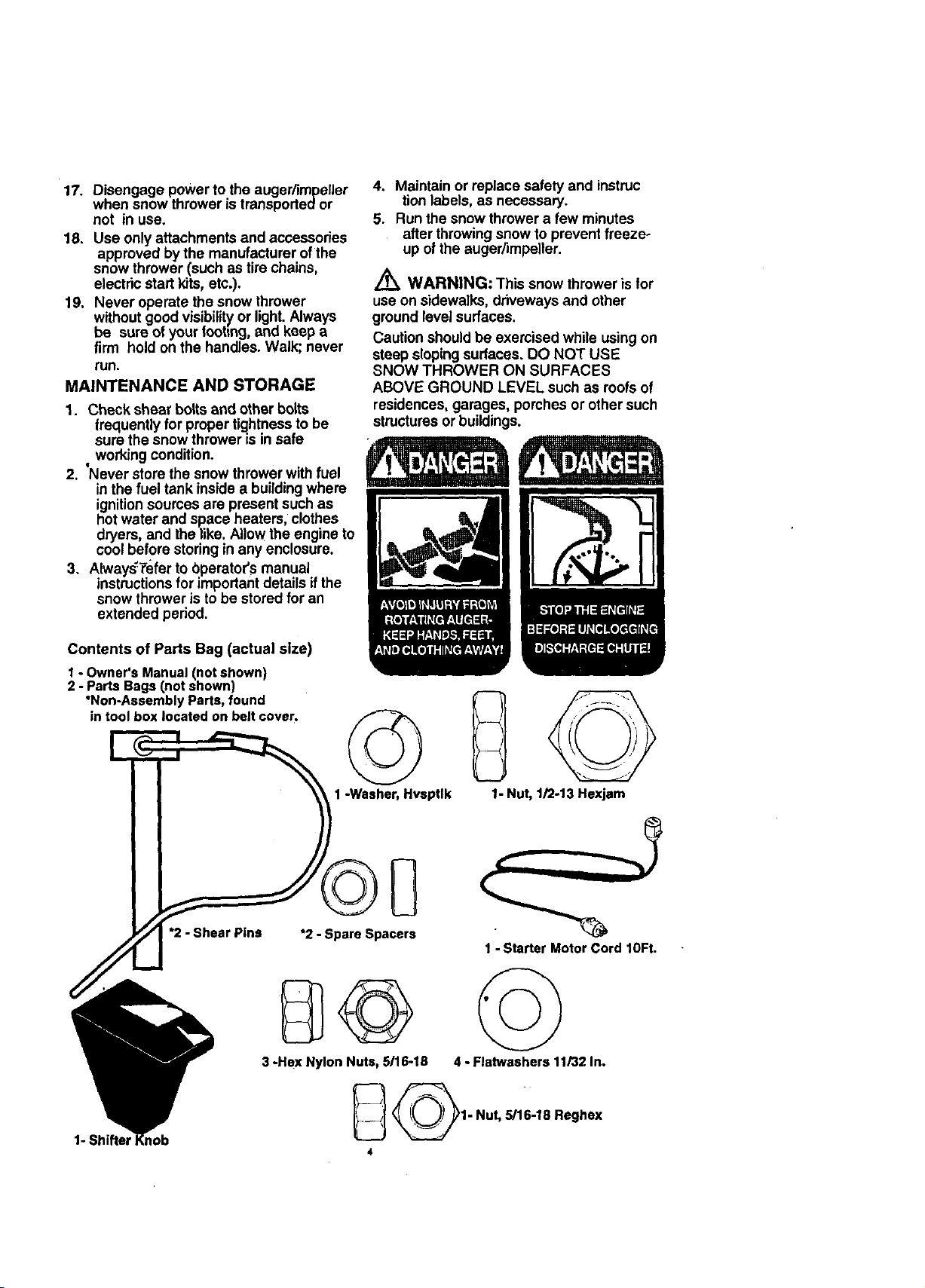
Contents of Parts Bag (actual size)
I ° Owner's Manual (not shown)
2 - Parts Bags (not shown)
*Non-Assembly Parts, found
in tool box located on belt cover.
*2 - Shear Pins
B©
3 -Hex Nylon Nuts,5116-18
©
1-Washer, Hvsptlk
*2- Spare Spacers
Q
1- Nut, 1/2-13Hexjam
1 - Starter Motor Cord 10Ft.
4 -Flatwashers 11/32In.
1- Shifter
_1" Nut, 5/16-18 Reghex
4
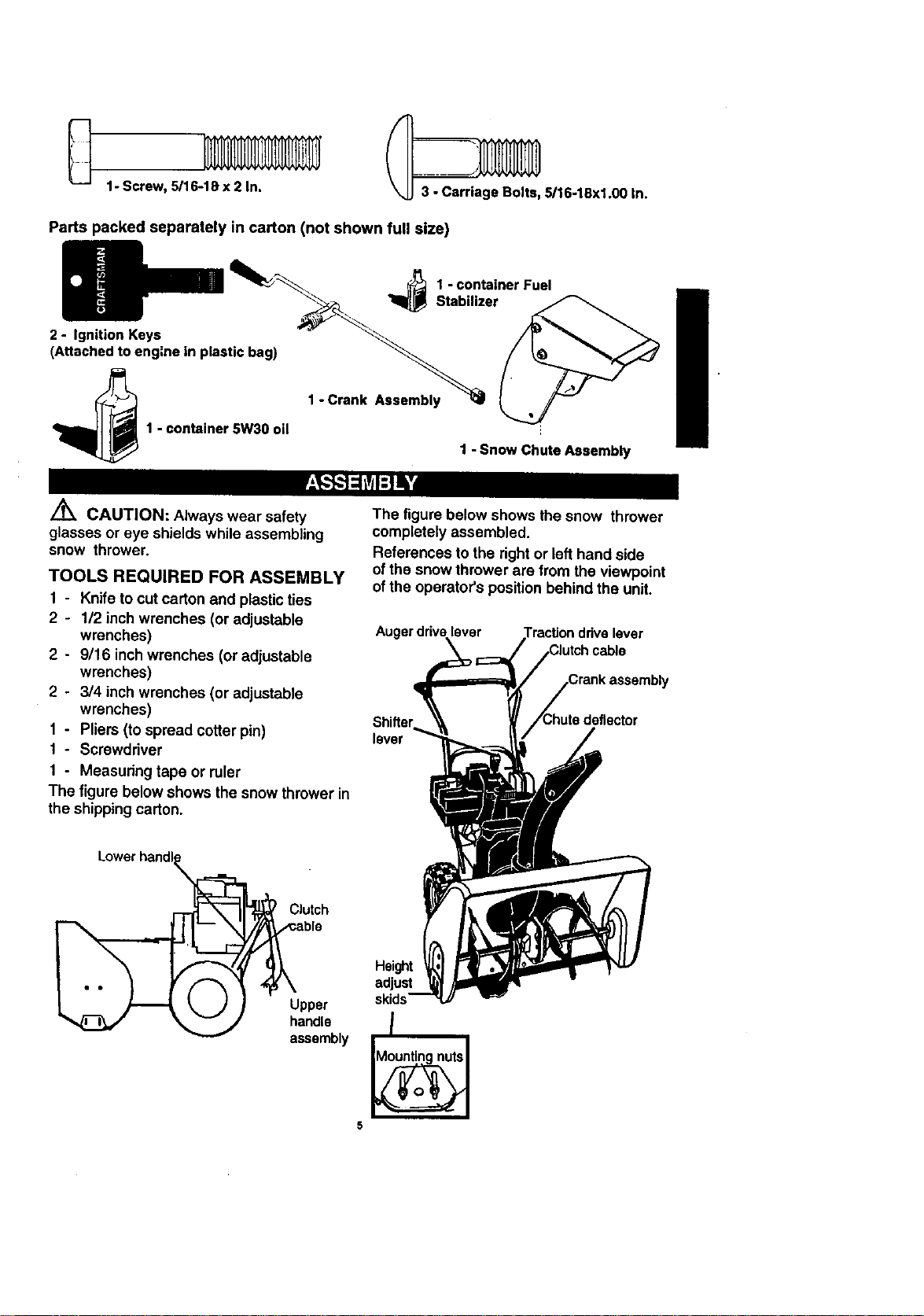
1- Screw, 5/16-1Sx 2 In.
Parts packed separately in carton (not shown full size)
_ _ 1 - container Fuel
2 - Ignition Keys _ _'_
(Attachedtoeng=nein
plastic bag)
_ 5/16-18xl.00 In.
StabI.zer
1 - container 5W30 oll ',
Z_ CAUTION: Always wear safety
glasses or eye shieldswhile assembling
snow thrower.
TOOLS REQUIRED FOR ASSEMBLY
1 - Knife to cut carton and plastic ties
2 - 1/2 inch wrenches (or adjustable
wrenches)
2 - 9/16 inchwrenches (oradjustable
wrenches)
2 - 3/4 inch wrenches (or adjustable
wrenches)
1 - Pliers (to spread cotter pin)
1 - Screwdriver
1 - Measuring tape or ruler
The figure below shows the snow thrower in
the shipping carton.
1 - Crank Assembly
1 - Snow Chute Assembly
The figure below shows the snow thrower
completely assembled.
References to the right or Lefthand side
ofthe snow thrower are from the viewpoint
of the operator's position behind the unit.
lever
lever
Clutch
Upper
handle
assembly
Height t
adjust =
skids--
I
5
TO REMOVE SNOW THROWER
FROM CARTON
• Locate and remove container of 5W30 oil.
• Locate all parts packed separately and
remove from the carton.
NOTE: Place fuel stabilizer in a safe place
untilneeded for storage.
• Remove and discard the packing material
from around the snow thrower.
• Gut all four comers of the carton from top
to bottom and lay the panels flat.
• Roll the snow thrower off the carton by
pulling on the lower handle. CAUTION:
DO NOT back over cables.
• Remove the packing material from
handle assembly and plastic protectoron
top of auger housing.
• Cut ties securing the clutch controlcables
tothe lower handle and lay cables back
away from the motor frame,
TO INSTALL THE UPPER HANDLE
AND CRANK ASSEMBLY
• Cut tie holding shift rod to lower handle
and move shifter to the firstgear.
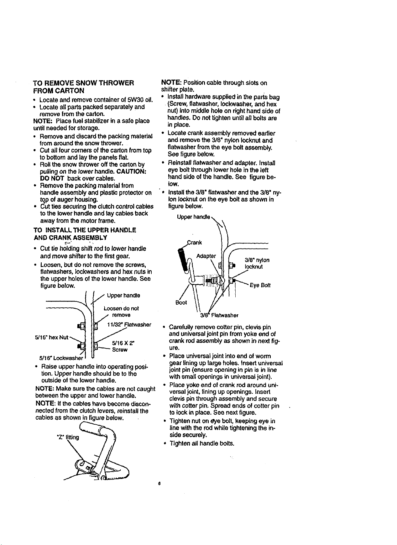
• Loosen, but do not remove the screws,
flatwashers, Iockwashers and hex nuts in
the upper holes ofthe lower handle. See
figure below.
Upper handle
Loosen do not
remove
11/32" Ratwasher
5/1
5/16 X 2,
5/16" Lockwasher
• Raise upper handle into operating posi-
tion. Upper handle should be to the
outside of the lower handle.
NOTE: Make surethe cables are not caught
between the upper and lower handle.
NOTE: If the cables have become discon-
nected from the clutch levers, reinstall the
cables as shown in figure below.
'Z_fitting
NOTE: Position cable through slots on
shifterplate.
• Install hardware supplied in the pads bag
(Screw, tiatwasher, Iockwasher, and hex
nut) into middle hole on righthand side of
handles. Do not tighten untilall bolts are
in place.
• Locate crank assembly removed earlier
and remove the 3/8' nylon Iocknut and
flatwasher from the eye bolt assembly.
See figure below.
• Reinstall flatwasher and adapter. Install
eye bolt through lower hole in the left
hand side of the handle. See figure be-
low.
"e
install the 3/8" flatwasher and the 3/8" ny-
lon Iocknut on the eye bolt as shown in
figure below.
3/8" nylon
Iocknut
e Bolt
Boot
• Carefully remove cotter pin, clevis pin
and universaljoint pin from yoke end of
crank rodassembly as shown in next fig-
ure.
• Place universaljoint into end ofworm
gear liningup large holes. Insert universal
jointpin (ensure opening in pin is in line
with small openings in universal joint).
• Place yoke end of crank rod around uni-
versal joint, lining up openings. Insert
clevis pin through assembly and secure
with cotter pin. Spread ends of cotter pin
to lock in place. See nextfigure.
• Tighten nut on eye bolt, keeping eye in
linewith the rod whiletightening the in-
side securely.
• Tighten allhandle bolts.
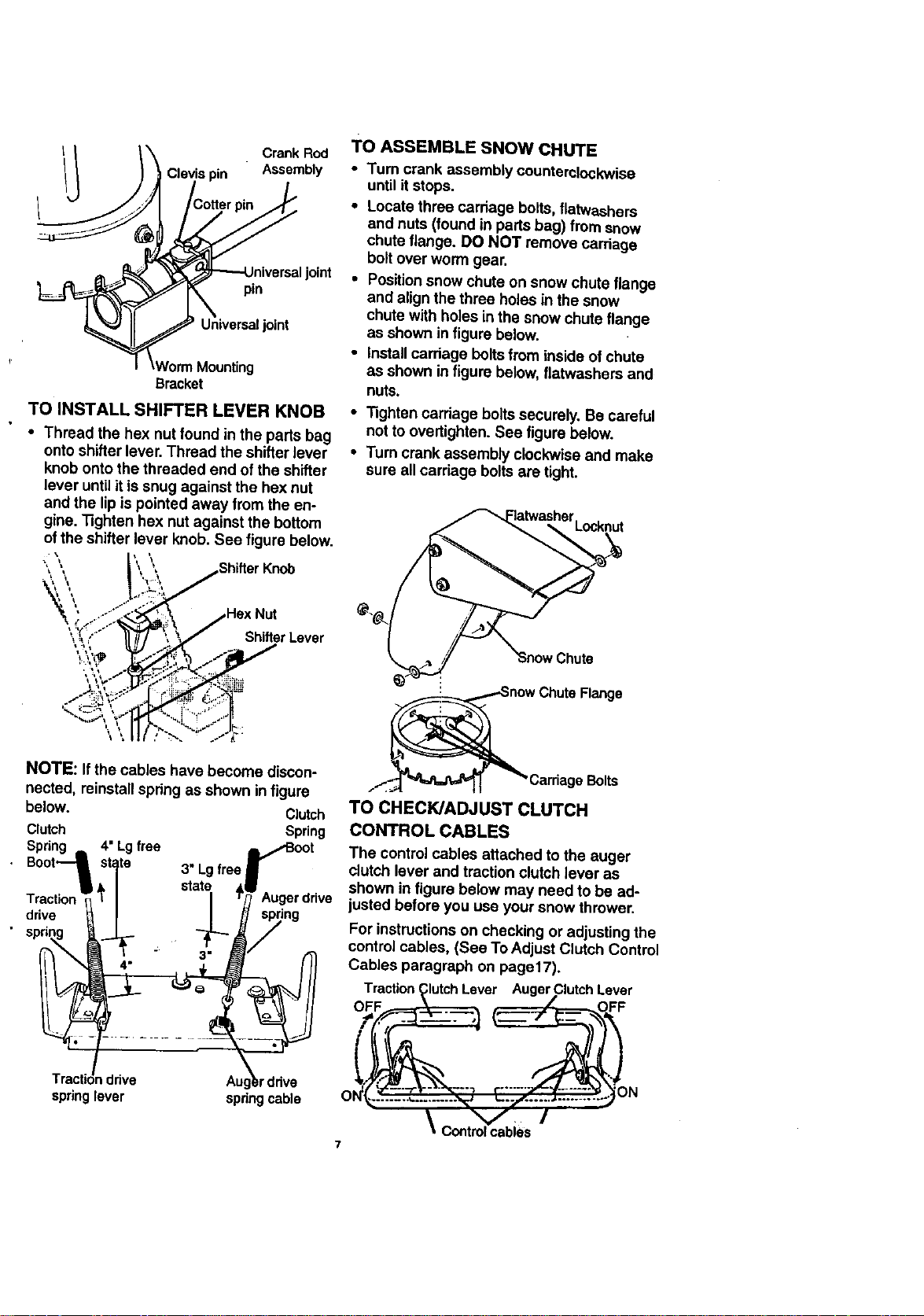
Crank Rod
Assembly
pin
Universaljoint
r
Bracket
TO INSTALL SHIFTER LEVER KNOB
• Thread the hex nut found in the parts bag
onto shifter lever.Thread the shifter lever
knob onto the threaded end of the shifter
lever until it is snug against the hex nut
and the lip is pointed away from the en-
gine. "5ghten hex nut against the bottom
of the shifter lever knob. See figure below.
TO ASSEMBLE SNOW CHUTE
• Turn crank assembly counterclockwise
until it stops.
• Locate three carriage bolts,flatwashers
and nuts (found in parts bag) from snow
chute flange. DO NOT remove carriage
bolt over worm gear.
joint
• Positionsnow chute on snow chute flange
and align the three holes in the snow
chute with holes inthe snow chute flange
as shown in figure below.
• Install carriage boltsfrom inside of chute
as shown in figure below, flatwashers and
nuts.
• "Nghtencarriage bolts securely, Be careful
not to overtighten. See figure below.
• Turn crank assembly clockwise and make
sure all carriage boltsare tight.
Locknut
Shifter Lever
NOTE: If the cables have become discon-
nected, reinstall spring as shown infigure
below. Clutch
Clutch Spring
Spring 4" Lg free ,/Boot
• Boot_ _t_te 3" Lgtree
Tractior
drive
spring
Tractic_
sprin!
,drive Aug_rdrive
lever springcable
Augerdrive
ing
Bolts
TO CHECK/ADJUST CLUTCH
CONTROL CABLES
The control cables attached to the auger
clutch lever and traction clutch lever as
shown in figure below may need to be ad-
justed before you use your snow thrower.
For instructionson checking or adjusting the
controlcables, (See To Adjust Clutch Control
Cables paragraph on page17).
actionClutchLever AugerClutchLever
0 ................... , --- ............... Z N
_ Controlcables
HOW TO SET UP YOUR SNOW
THROWER
• Your snow thrower is equipped with height
adjustskids (see second figure on page 5)
on the outside of the auger housing. To
adjust the skid height for different
conditions, (see To Adjust Skid Height
paragraph on page 17).
•/ CHECKLIST
Before you operate your new snow
thrower, to ensure that you receive the
best performance and satisfaction from this
quality product, please review the following
checklist:
,/ All assembly instructionshave been
completed.
,/ The discharge chute rotates freely.
,," No remaining loose parts incarton.
While learning how to use your snow
thrower, pay extra attention to the following
important items:
,/4" Engine oil is at proper level.
•/,/ Make sure gas tank is filled properly
with clean, fresh, unleaded gasoline.
// Become familiar with all controls-their
locationand function. Operate controls
before starting engine.
Auger Drive Lever - Starts and stops the
auger and impeller (snow gathering and
throwing).
Traction Drive Lever - Propels the snow
thrower forward and in reverse.
Speed Shitter Lever - Selects the speed of
snow thrower (6 speeds forward and 2
speeds reverse).
Crank Assembly - Changes the directionof
snow throwing through the discharge chute.
Chute Deflector- Changes the distance
the snow is thrown.
Discharge Chute - Changes the direction
the snow is thrown.
Height Adjust Skids - Adjusts the ground
clearance of the auger housing.
Ignition Key - Must be inserted to start the
engine.
Recoil Starter Handle - Starts the engine
manually.
Choke Control - Used to start a cold en*
gine.
Primer Button - Injects fuel directly intothe
carburetor manifoldfor fast starts in cold
weather.
Throttle Control - Controls the engine
speed.
Electric Starter Button - Used to start the
engine usingthe 120 V electric starter.
Shear Bolt - Shear bolts are designed to
break (to protect the machine) if an object
becomes lodgedinthe auger housing. Use
ofa harder boltwill destroy the protection
provided by the shear bolt.
Toolbox- Spare shear pins and spacers are
located in toolbox.
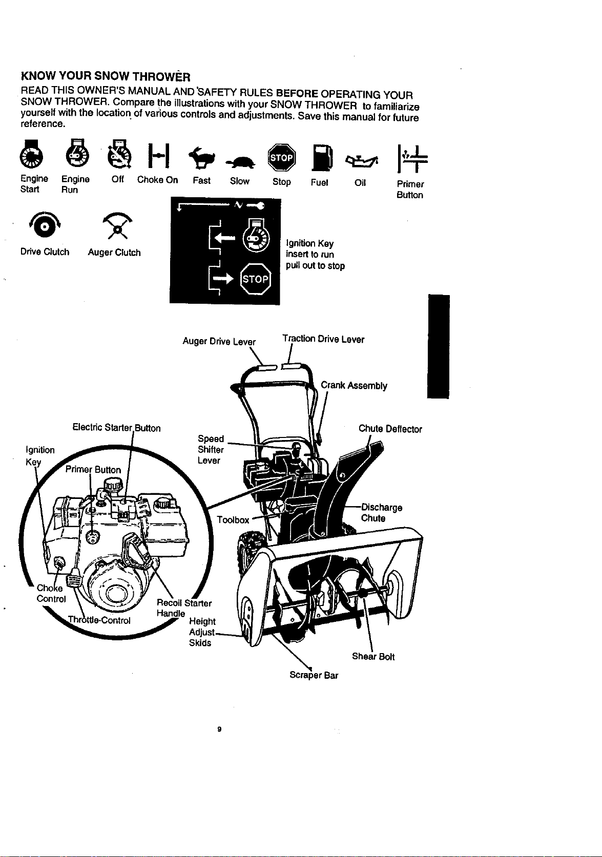
KNOWYOURSNOWTHROWF:R
READTHISOWNER'SMANUALAND'SAFETYRULESBEFOREOPERATINGYOUR
SNOWTHROWER.Comparethe illustrationswith your SNOW THROWER to familiarize
yourselfwith the location of various controls and adjustments. Save thismanual for future
reference.
I-I
Engine Engine Off Choke On Fast Slow Stop Fuel Oil Pdrner
Start Run Button
Drive Clutch Auger Clutch
ElectricStartel
Ignition
AugerDriveLever
\
Speed
Shifter
Lever
Ignition Key
inserttorun
pull outto stop
TractionDriveLever
Crank Assembly
Chute Deflector
Chute
Control
Skids
Shear Bolt
Bar
The'operation of any snow thrower can re-
sult in foreign objects being thrown intothe
eyes, which can resuttin severe eye dam-
age. Always wear safety glasses or eye
shields while operating the snow thrower.
We recommend standard safety glasses or
a wide vision safety mask for over your
glasses, available at Craftsman Retail
• Stores or Service Centers.
/_ CAUTION: Read owner's manual
before operating machine. Never direct
discharge toward bystanders. Release the
auger control bar and stop the engine
before unclogging discharge chute or auger
housing and before leaving the machine,
HOWTO USEYOUR SNOW
THROWER
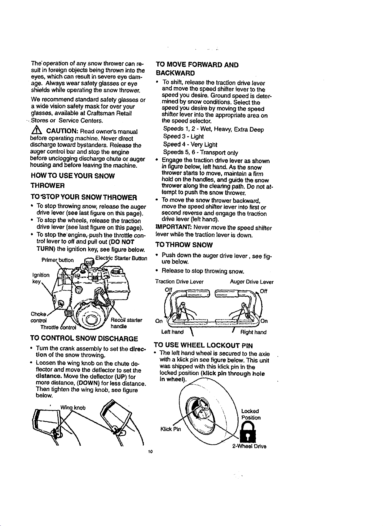
TO<JTOP YOUR SNOW THROWER
• To stop throwing snow, release the auger
drive lever (see last figure on this page).
• To stop the wheels, release the traction
drive lever (see last figure on this page).
• To stop tbe'engine,_pushthe throttle con-
trel lever to off and pull out (DO NOT
TURN) the ignition key, see figure below.
button
Ignition
key,
TO MOVE FORWARD AND
BACKWARD
• To shift, release the traction drive lever
and move the speed shifter lever to the
speed you desire. Ground speed is deter-
mined by snow conditions. Select the
speed you desire by moving the speed
shifterlever into the appropriate area on
the speed selector.
Speeds 1, 2 - Wet, Heavy, Extra Deep
Speed 3 - Light
Speed 4 - Very Light
Speeds 5, 6 - Transport only
,' Engage the tractiondrive lever as shown
in figure below, left hand. As the snow
thrower starts to move, maintain a firm
hold on the handles, and guide the snow
thrower along the clearing path. Do not at-
tempt to push the snow thrower.
• To move the snow thrower backward,
move the speed shifterlever into first or
second reverse and engage the traction
drive lever (left hand).
IMPOR3"ANT: Never move the speed shifter
lever whilethe traction lever is down.
TOTHROW SNOW
• Push down the auger drive lever, see fig-
ure betow.
• Release to stop throwing snow.
TractionDriveLaver AugerDriveLever
control On
handle
TO CONTROLSNOWDISCHARGE
• Turn the crank assembly to set the direc-
tion ofthe snow throwingo
• Loosen the wing knob on the chute de-
flector and move the deflector to set the
distance. Move the deflector (UP) for
more distance, (DOWN) for less distance.
Then tightenthe wing knob, see figure
below.
knob
TO USE WHEEL LOCKOUT PiN
• The left hand wheel is secured to the axle
io
Left hand Right hand
with a klickpin see figure below. This unit
was shipped with this klick pin in the
locked position (Idick pin through hole
in wheel).
Locked
Position
2-Wheel Odve
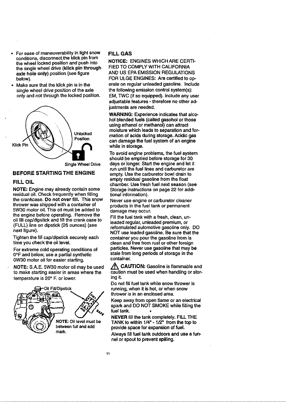
• For ease of maneuverability in light snow
conditions,disconnect.the klick pin from
the wheel locked positionand push into
the single wheel ddva (kllck pin through
axle hole only)position (see figure
below).
• Make sure that the klick pin is in the
single wheel ddve position of the axle
only and not through the locked position.
Unlocked
Position
Klick Pin
Single Wheel Drive
BEFORE STARTING THE ENGINE
FILL OIL
NOTE: Engine may already contain some
residual oil. Check frequently when filling
the crankcase. Do not over fill. This snow
thrower was shipped with a container of
5W30 motor oil. This oil must be added to
the engine before operating. Remove the
oilfillcap/dipstick and fill the crank case to
(FULL) line on dipstick (26 ounces) (see
next figure).
Tighten the fill cap/dipstick securely each
time you check the oil level.
For extreme cold operating conditions of
0°F and below, use a partialsynthetic
0W30 motor oilfor easier starting.
NOTE: S.A.E. 5W30 motor oil may be used
to make starting easier inareas where the
temperature is 20° F. or lower.
FilVDipstick
between full and add
mark.
FILL GAS
NOTICE: ENGINES WHICH ARE CERTI-
FIED TO COMPLY WITH CALIFORNIA
AND US EPA EMISSION REGULATIONS
FOR ULGE ENGINES: Are certified to op-
erate on regular unleaded gasoline. Include
the following emission control system(s):
EM, TWC (if so equipped). Include any user
adjustable features - therefore no other ad-
justments are needed.
WARNING: Expedence indicates that alco-
hol blended fuels (called gasohol or those
using ethanol or methanol) can attract
moisture which leads to separation and for-
mation of acids dudng storage. Acidic gas
can damage the fuel system of an engine
while in storage.
To avoid engine problems, the fuel system
should be emptied before storage for 30
days or longer. Start the engine and let it
run until the fuel lines and carburetor are
empty. Use the carburetor bowl drain to
empty residual gasoline from the float
chamber. Use fresh fuel next season (see
Storage instructionson page 22 for addi-
tional information).
Never use engine orcarburetor cleaner
products in the fuel tank or permanent
damage may occur.
Fill the fuel tank with a fresh, clean, un-
leaded regular, unleaded premium, or
reformulated automotive gasoline only. DO
NOT use leaded gasoline. Be sure that the
container you pour the gasoline from is
clean and free from rust or other foreign
particles. Never use gasoline that may be
stale from long pedods of storage in the
container.
/_ CAUTION: Gasoline is flammable and
caution must be used when handling or stor-
ing it.
Do not fill fuel tank while snow thrower is
running,when it ishot, or when snow
thrower is in an enclosed area.
Keep away from open flame or an electdcal
spark and DO NOT SMOKE while filling the
fuel tank. •
NEVER fin the tank completely. FILL THE
TANK to within 1/4" - 1/2" from the top to
provide space for expansion offuel.
Always fillfuel tank outdoors and use a fun-
nel or spout to prevent spilling.
11
 Loading...