

Craftsman 536886121 Owner’s Manual
OWN
R'S
UAL
MODEL NO.
536.886121
Caution:
Read and Follow
All Safety Rules
and Instructions
Before Operating
This Equipment
®
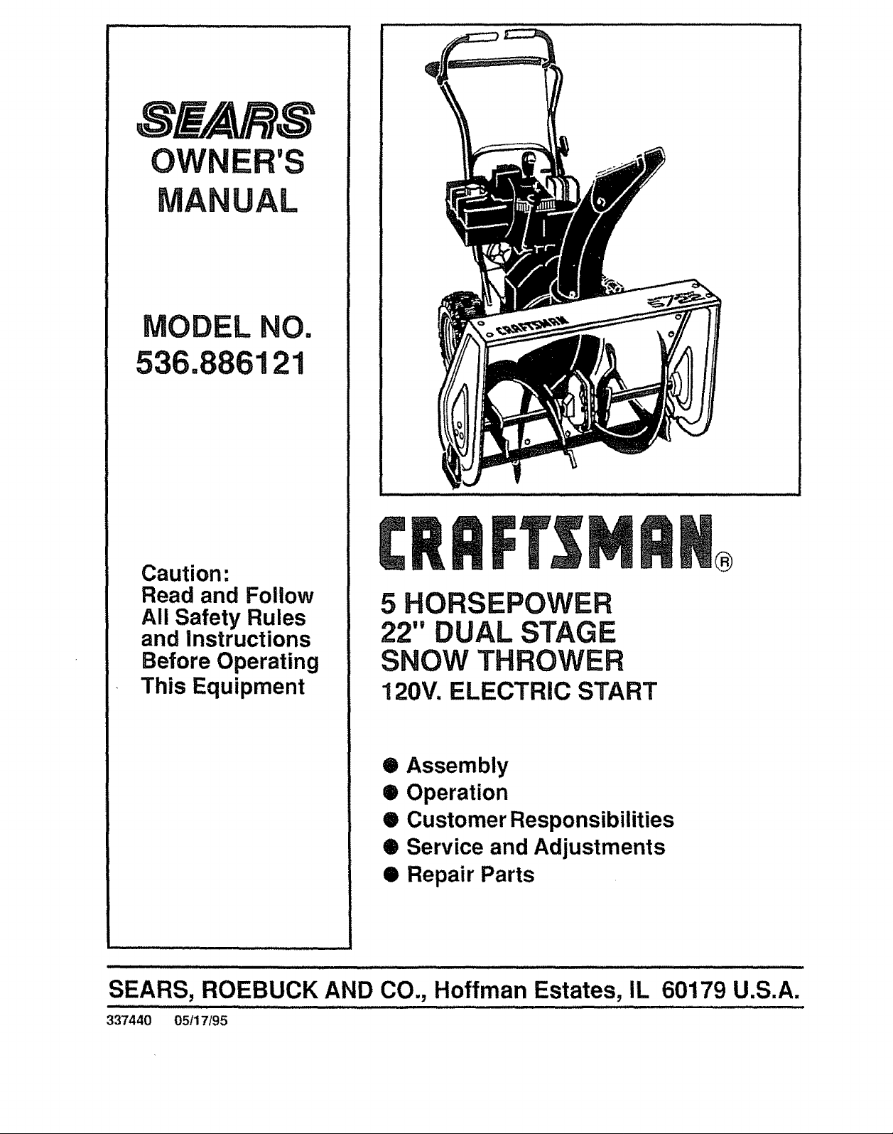
5 HORSEPOWER
22" DUAL STAGE
SNOW THROWER
120V. ELECTRIC START
• Assembly
• Operation
• Customer Responsibilities
• Service and Adjustments
Q Repair Parts
SEARS, ROEBUCK AND CO., Hoffman Estates, IL
337440 05/17/95
60179 U.S.A.
SAFETY RULES
PLACE WIRE WHERE IT CANNOT CONTACT SPARK PLUG
CAUTION: ALWAYS DISCONNECT SPARK PLUG WIRE AND
TO PREVENT ACCIDENTAL STARTING WHEN SETTING-UP,
TRANSPORTING, ADJUSTING OR MAKING REPAIRS.
IMPORTANT
SAFETY STANDARDS REQUIRE OPERATOR PRESENCE CONTROLS TO MINIMIZE THE
RISK OF INJURY. YOUR SNOW THROWER IS EQUIPPED WITH SUCH CONTROLS, DO NOT
ATTEMPT TO DEFEAT THE FUNCTION OF THE OPERATOR PRESENCE CONTROL UNDER
ANY CIRCUMSTANCES.
TRAINING 6,
1. Read the operator's manual carefully_ Be
thoroughly familiar with the controls and the 7,
proper use of the snow thrower. Know how to
stop the snow thrower and disengage the
controls quickly.
2_ Never allow chUdren to operate the snow thrower
and keep them away while it is operating. Never
allow adults to operate the snow thrower without
proper instruction, Do not carry passengers., 9
3. Keep the area of operation clear of all persons,
particularly small children, and pets..
4. Exercise caution to avoid slipping or falling,
especially when operating in reverse
PREPARATION
1. Thoroughly inspect the area where the snow
thrower is to be used and remove all doormats,
sleds, boards, wires, and other foreign objects.
2. Disengage all clutches and shift into neutral
before starting the engine (motor).
3. Do not operate the snow thrower without wearing
adequate winter outer garments Wear footwear
that will improve footing on slippery surfaces.
4 Handle fuel with care; _tis highly flammable.
(a) Use an approved fuel container,
(b) Never remove fuel tank cap or add fuel to a
runningengineor hot engine°
(c) Fill fuel tank outdoors with extreme care
Never fill fuel tank indoors_
(d) Replace fuel tank cap securely and wipe up
spilled fuel
(e) Never store fuel or snow thrower with fuel in
the tank inside of a building where fumes may
reach an open flame or spark.
(f) Check fuel supply before each use, allowing
space for expansion as the heat of the engine
(motor) and/or sun can cause fuel to expand.
5_
Use extension cords and receptacles as specified
by the manufacturer for all snow throwers with
electric drive motors or electric starting motors.
Adjust the snow thrower height to clear gravel or
crushed rock surfaces.
Never attempt to make any adjustments while the
engine (motor) is running (except when
specifically recommended by the manufacturer)
8-
Let engine (motor) and snow thrower adjust to
outdoor temperatures before starting to clear
snow,,
Always wear safety glasses or eye shieEdsduring
operation or while performing an adjustment or
repair to protect eyes from foreign objects that
may be thrown from the snow thrower-
OPERATION
1.. Do not put hands or feet near or under rotating
parts Keep clear of the discharge opening at all
times.
2. Exercise extreme caution when operating on or
crossing gravel drives, walks, or roads Stay alert
for hidden hazards or traffic.
3. After striking a foreign object, stop the engine
(motor), remove the wire from the spark plug,
disconnect the cord on electric motors,
thoroughly inspect the snow thrower for any
damage, and repair the damage before restarting
and operating the snow thrower.
zl_ If the snow thrower should start to vibrate
abnormally, stop the (motor) and check
immediately for the cause Vibration is generally
a warning of trouble..
5. Stop the engine (motor') whenever you leave the
operating position, before unclogging the auger/
impeller housing or discharge guide, and when
making any repairs, adjustments, or inspections
6 When cleaning, repairing, or inspecting, make
certain the augedimpeHer and all moving parts
have stopped. Disconnect the spark plug wire
and keep the wire away from the plug to prevent
accidental starting.
7. Take all possible precautions when leaving the
snow thrower unattended Disengage the auger/
impeller, shift to neutral, stop engine, and
remove key.
,l_lJIl_ II'l ......
SAFETY RULES
8. Do not tun the engine indoors, except when starting
the engine and for transporting the snow thrower in
or out of the building. Open the outside doors;
exhaust fumesare dangerous(containing CARBON
MONOXIDE,an ODORLESS and DEADLYGAS)
9° Do not clear snow across the face of slopes
Exercise caution when changing direction on
slopes_Do not attempt to clearsteep slopes
10. Never operate the snow thrower without proper
guards, platesor othersafety protectivedevices
in place.
11o Never operate the snow thrower near glass
enclosures, automobiles, window wells,
drop-otis, and the like without proper adjustment
of the snow discharge angle. Keep children and
pets away.
12. Do not overload the machine capacity by
attempting to clear snow at too fast a rater
13. Never operate the snow thrower at high transport
speeds on slippery surfaces. Look behind and
use care when backing
14 Never direct discharge at bystanders or allow
anyone in front of the snow thrower.
15. Disengage power to the auger/impeller when
snow thrower is transported or not in use..
16 Llse only attachments and accessories approved
by the manufacturer of the snow thrower (such
as tire chains, electric start kits, etc.),,
17_ Never operate the snow thrower without good
visibilityor light. Always be sure of your footing,
and keep a firm hold on the handles, Walk; never
run.
MAINTENANCE AND STORAGE
1. Check shear bolts and other bolts frequently for
proper tightness to be sure the snow thrower
is in safe working condition
2. Never store the snow thrower with fuel in the fuel
tank inside a building where ignitionsources are
present such as hot water and space heaters,
clothes dryers, and the like,. Allow the engine to
cool before storing in any enclosure,
3o Always refer to operator's manual instructions
for important details if the snow thrower is to be
stored for an extended period
4 Maintain or replace safety and instruclion labels,
as necessary..
5. Run the snow thrower a few minutes after
throwing snow to prevent freeze-up of the auger/
impeller.
WARNING
This snow thrower Is for use on sidewalks,
driveways, and other ground level surfaces°
CAUTION should be exercised while using on
steep sloping surfaces. DO NOT USE SNOW
THROWER ON SURFACES ABOVE GROUND
LEVEL such as roofs of residences, garages,
porches or other such structures or buildings.
LOOK FOR THIS SYMBOL TO POINT OUT
IMPORTANT SAFETY PRECAUTIONS. IT
MEANS--ATTENTION!!! BECOME
ALERTI!! YOUR SAFETY IS INVOLVED.
......c=.0r,ia o s.io,,65WA""i.G!
_i The engine exhaust from this product
3
contains chemicals known to the State
of California to cause cancer, birth de-
fects or other reproductive harm.
CONGRATULATIONS on your purchase of a Sears
Craftsman Snow Thrower it has been designed, engi-
neered and manufacturedtogive youthe best possible
dependability and performance
Should you experience any problem you cannot easily
remedy, please contact your nearest Sears Service
CenterlDepartmenL Sears hascompetent, well-trained
techniciansand the proper toolsto service or repairthis
unity
Please read and retainthismanual The instructions will
enableyoutoassembleandmaintainyoursnowthrower
properly. Always observe the "SAFETY RULES:
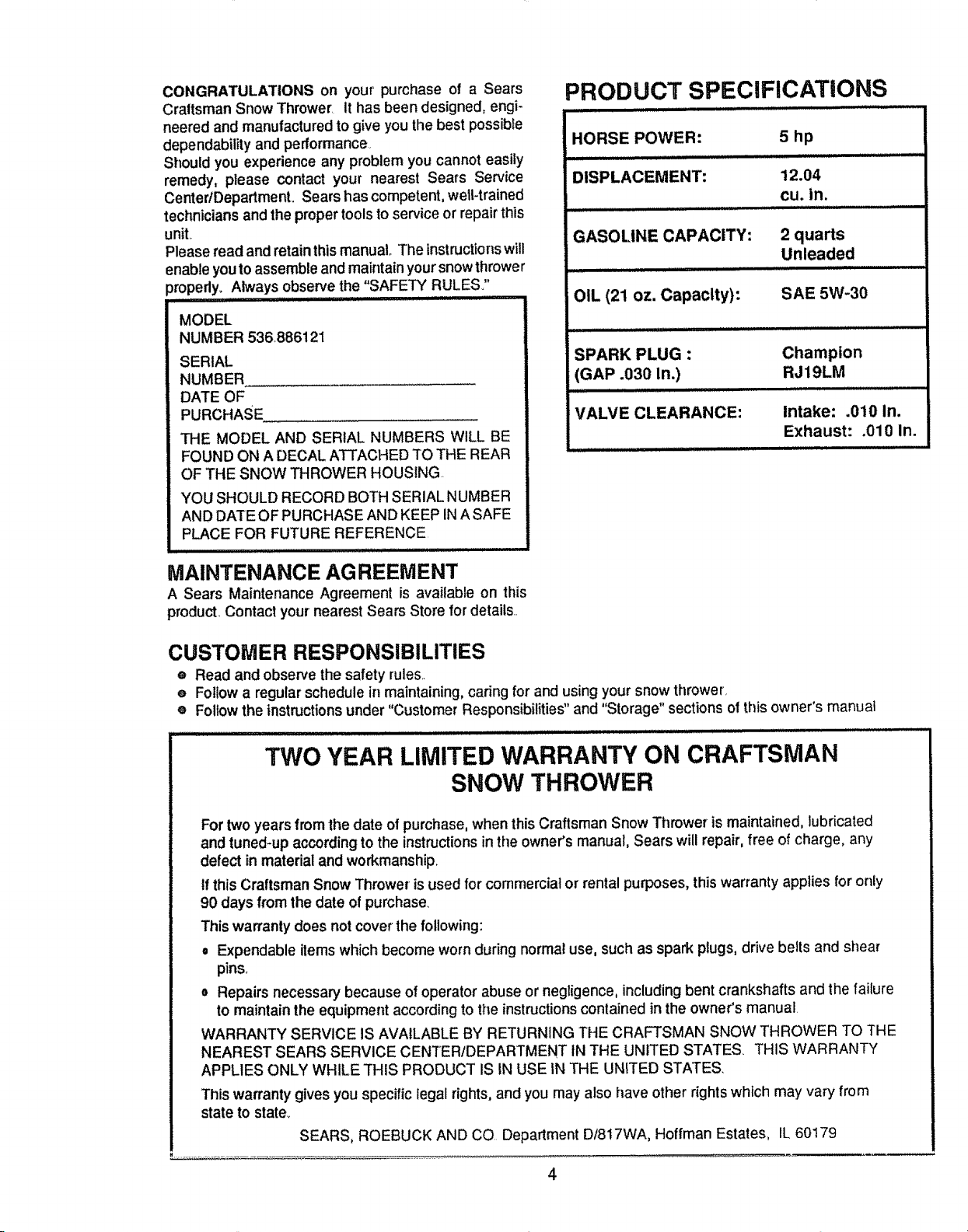
: RODUCT SPECIFICATIONS
llll i
HORSE POWER: 5 hp
DISPLACEMENT: 12.04
cu. in.
GASOLINE CAPACITY: 2 quarts
Unleaded
OIL (21 oz. Capacity): SAE 5W-30
SPARK PLUG : Champion
(GAP .030 in.) RJ19LM
VALVE CLEARANCE: Intake: .010 In.
Exhaust: .010 In.
MAINTENANCE AG REEMENT
A Sears Maintenance Agreement is available on this
product Contact yournearest Sears Store for details
CUSTOMER RESPONSIBILITIES
® Read and observethe safety rules
e Followa regularschedule in maintaining,caring for and using your snow thrower
e Followthe instructions under "Customer Responsibilities" and "Storage" sections of thisowner's manual
TWO YEAR LIMITED WARRANTY ON CRAFTSMAN
SNOW THROWER
For two years fromthe date of purchase,when this Craftsman Snow Thrower is maintained, lubricated
and tuned-up according to the instructions in the owner's manual, Sears will repair, free of charge, any
defect in material and workmanship_
If this Craftsman Snow Thrower is used for commercial or'rental purposes, this warranty applies for only
90 days from the date of purchase.
This warranty does not cover the following:
e Expendable items which become worn during normal use, such as spark plugs, drive belts and shear
pins.
o Repairs necessary because of operator abuse or negligence, including bent crankshafts and the failure
to maintain the equipment according to the instructions contained in the owner's manual
WARRANTY SERVICE IS AVAILABLE BY RETURNING THE CRAFTSMAN SNOW THROWER TO THE
NEAREST SEARS SERVICE CENTERIDEPARTMENT tNTHE UNITED STATES THIS WARRANTY
APPLIES ONLY WHILE THIS PRODUCT IS IN USE IN THE UNITED STATES.
This warranty gives you specific legal rights, and you may also have other rights which may vary from
state to state_
SEARS, ROEBUCK AND CO Department DI817WA, Hoffman Estates, IL 60179
4
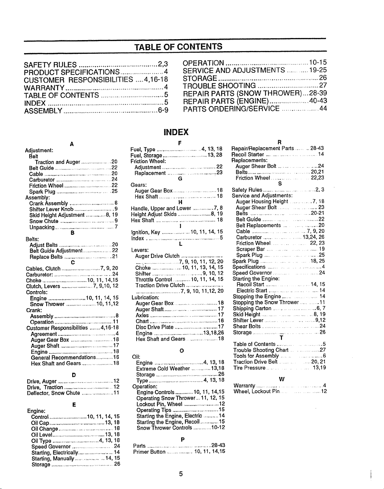
SA FEm_ RULES ........................................ 2_3
PRODUCT SPECIFICATIONS .......................... 4
CUSTOMER RESPONSIBILITIES .... 4,16-t8
WARRANTY ........................................................ 4
TABLE OF CONTENTS ............................................5
INDEX ......................................................................5
ASSEMBLY ..................................................... 6-9
A
Adjustment:
Belt
Traction and Auger .......................20
Belt Guide ..................................................22
Cable .........................................................20
Carburetor ....................................................24
Frictbn Wheel ................................................22
Spark Plug .............................................25
Assembly:
Crank Assembly ..................................8
Shifter Lever Knob .............................9
Skid Height Adjustment ...............8, 19
Snow Chute ...........................................9
Unpacking .........................................................7
B
Bells:
Adjust Belts .............................................20
Belt Guide Adjustment ..........................22
Replace Belts ...........................................21
C
Cables, Clutch ..............................7, 9, 20
Carburetor: ...................................................24
Choke ................................10, 11, t4,15
Clutch, Levers .............................7, 9,10, 12
Controls:
Engine ......................... 10, 11, 14, 15
Snow Thrower ........................10, 11,12
Crank:
Assembly ...............................................8
Operation ................................................11
Customer Responsibilities ..........4,16-18
Agreement .............................................4
Auger Gear Box ........................................18
Auger Shaft ............................................17
Engine....................................................i8
General Recommendations ................16
Hex Shaft and Gears .........................18
D
Drive, Auger ..................................................12
Drive, Traction..........................................12
Deflector, Snow Chute ...........................11
E
Engine:
Control ..................................10, tl, 14, 15
Oil Cap .........................................13, 18
OilChange ...................................................18
OilLevel ......................................13, 18
OUType ..................................4, 13, 18
Speed Governor .....................................24
Starting, Electrically...............................14
Starting, Manually ......................14, 15
Storage ...................................................26
Fuel, Type ....................................4, 13, 18
Fuel, Storage .......................................t3, 28
Friction Wheel:
Adjustmen!..................................................22
Replacement ...................................23
Gears:
Auger Gear Box .......................................18
He× Shaft ................................................18
Handle, Upper and Lower .................7, 8
Height Adjust Skids ...............................8, 19
Hex Shaft ...................................................18
Ignition, Key .......................I0, 11, !4, 15
Index.....................................................5
Levers:
Auger Drive Clutch .................................
........................................7, 9, 10, 11, t2, 20
Choke .........................10, 11, 13, !4, 15
Shitter .............................................9, 10, 12
Throttle Control ..............I 0, 11, 14, 15
Traction Drive Clutch ...............................
..........................................7, 9, 10, 11,12, 20
Lubrication:
Auger Gear Box .........................................18
Auger Shaft .............................................17
Axles ......................................................17
Chart .............................................................16
Dfsc Drive Plate ........................................17
Engine ....................................13,18,26
Hex Shaft and Gears ...........................18
Oil:
Engine ........................................4, !3, 18
Extreme Cold Weather ...............13,18
Storage .....................................................26
Type ......................................................4, 13, 18
Operation:
Engine Controls .............10, 11, 14,15
Operating Snow Thrower., 11, 12, 15
Lockout Pin, Wheel ............................12
Operating Tips ........................................15
Startingthe Engine, Electric .............14
Starting the Engine, Recoil ................15
Snow Thrower Controls ...............10-12
Parts ..............................................................28-43
Primer Button .....................10, 11, 14,15
INDEX
F
G
H
I
L
O
P
OPERATION .......................................................10-t 5
SERVICE AND ADJUSTMENTS ..............I9-25
STO RAG E ..................................................... 26
TROUBLE SHOOTING ..............................................27
REPAIR PARTS (SNOW THROWER),,,. 28-39
REPAIR PARTS (ENGINE) .........................40-43
PARTS ORDERING/SERVICE ....................... 44
R
RepairtReplacement Parts .......... 28-43
Recoil Starter ......................................14
Replacements:
Auger Shear Bolt .............................24
Belts ......................................... 20,21
Friction Wheel .................... 22,23
S
Safety Rules ......................................2, 3
Service and Adjustments:
Auger Housing Height .............. 7, !8
Auger Shear Boft ........................ 23
Belts ........................................... 20-21
Bell Guide ..................................... 22
Belt Replacements .................... 20
Cable ................................. 7, 9, 20
Carburetor .......................... 13,24, 26
Friction Wheel ..................... 22, 23
Scraper Bar .............................. t9
Spark Plug .............................. 25
Spark Plug .............................. t8, 25
Specifications ................................. 4
Speed Governor ........................... 24
Starting the Engine:
Recoil Start ........................ 14, t5
Electric Start ................................... t 4
Stopping the Engine ................. 14
Stopping the Snow Thrower ............ 11
Shipping Carton ...................................6, 7
Skid Height ......................................8, 19
Shifter Lever ................................ 9,12
Shear Bolts ....................................... 24
Storage ........................................... 26
T
Table of Contents ............................. 5
Trouble Shooting Chart ................... 27
Tools for Assembly .......................... 6
Traction Drive Belt .............. 20, 2t
Tire Pressure ................... 13,19
W
Warranty ............................................. 4
Wheel, Lockout Pin ...................... 12
CONTENTS OF
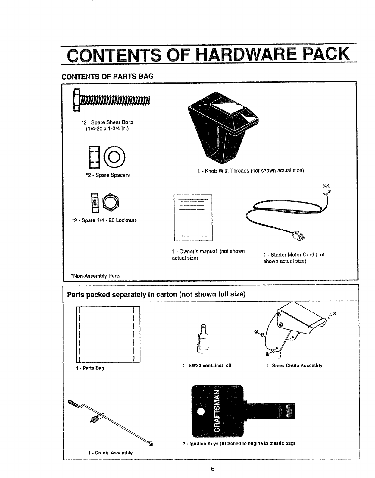
CONTENTS OF PARTS BAG
................................. ,,,,, ,,,,,,,,,,,,,,,,,,
"2 - Spare Shear Bolts
(1/4.20 x 1-3/4 In.)
DQ
*2 - Spare Spacers
"2 - Spare 1t4 - 20 Locknuts
HARDWARE PACK
1- Knob WithThreads (not shown actual size)
1 - Owner's manual (not shown
actual size)
*Non-Assembly Parts
Parts packed separately in carton (not shown full size)
I
I
I
i
I
1 - Parts Bag
1- 5W30 container oft
1 - Starter Molor Cord (not
shown actual size)
='_L
1 -Snow Chute Assembly
1 - Crank Assembly
2 - Ignition Keys (Attached to engine In ptastlc bag)
6
H ,,,,,i ,,i IIIIH,.I. II.I I I ,I Illll II I ,/'/ I,,,,,,, .....
AS LY
TOOLS REQUIRED FOR ASSEMBLY ......................................................
1 - Knife (to cut carton and plastic ties)
2 - !12 inch wrenches (or adjustable wrenches)
2 - 9116 inch wrenches (or adjustable wrenches)
2 - 3/4 inch wrenches (or adjustable wrenches)
t - Pliers (to spread cotter pin)
I- Screwdriver
1 - Measuring Tape or Ruler
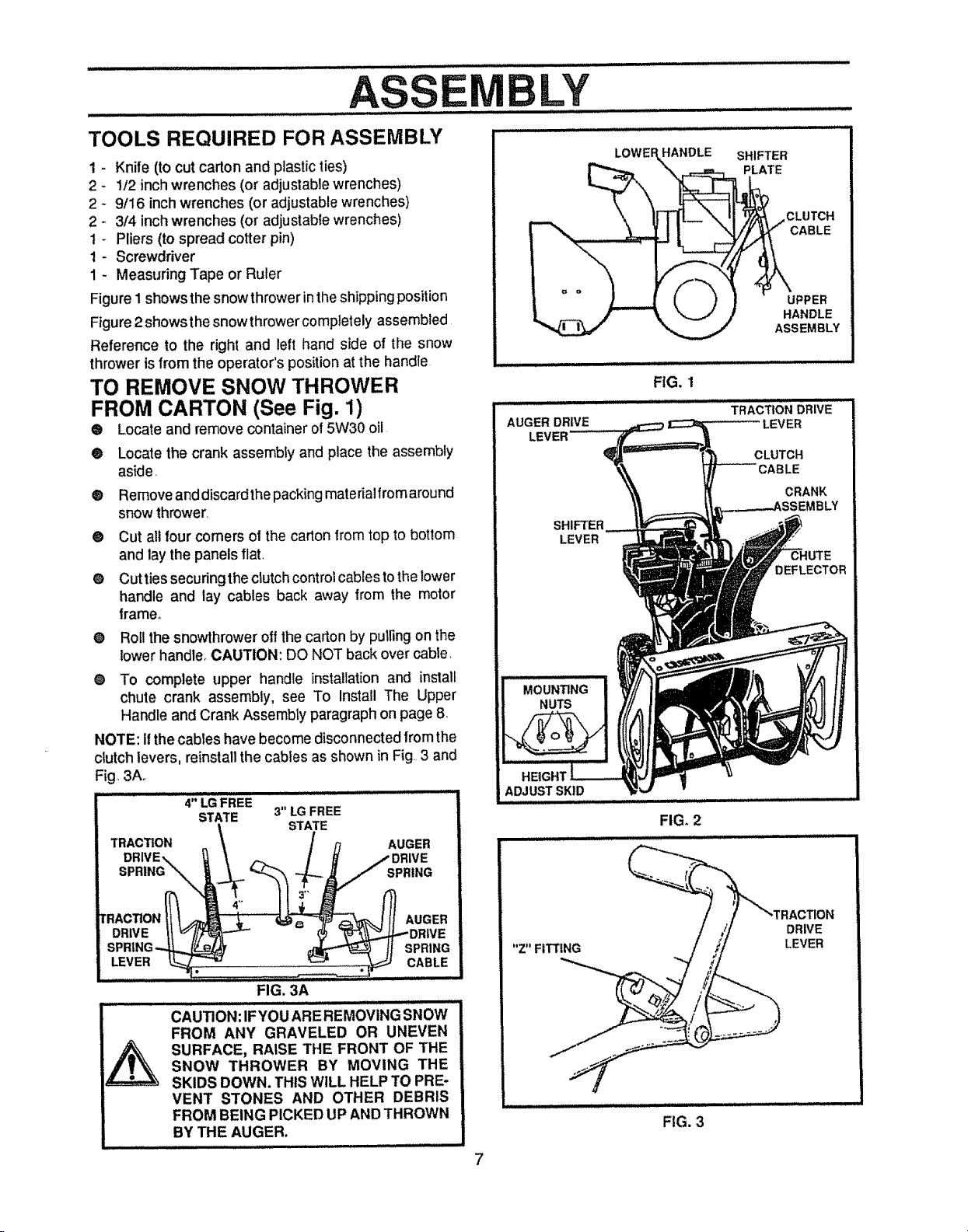
Figure 1 shows the snowthrower in theshipping position
Figure 2showsthe snowthrowercomptetely assembled
Reference to the right and left hand side of the snow
thrower is from the operator's position at the handle
TO REMOVE SNOW THROWER
FROM CARTON (See Fig. 1)
® Locate and remove container of 5W30 oil
• Locate the crank assembly and place the assembly
as{de,
® Remove and discardthe packing materialfrom around
snow thrower,
® Cut all four comers of the carton from top to bottom
and lay the panels flat.
e Cut ties securing the clutch control cables to the lower
handle and lay cables back away from the motor
frame°
O
Roll the snowthrower off the carton by puli_ngon the
lower handle_CAUTION: DO NOT back over cable.
O
To complete upper handle installationand install
chute crank assembly, see To Install The Upper
Handle and Crank Assembly paragraph on page 8
NOTE: Itthe cables have become disconnected from the
clutch levers, reinstall the cables as shown in Fig,3 and
Fig, 3Ao
........... 4" LG FREE
STATE 3" LG FREE
i i ill iqt ii mE HqLI II
STATE
LOWE HANDLE
FIG. 1
ADJUST SKID
FIG. 2
SHIFTER
PLATE
UPPER
HANDLE
ASSEMBLY
DRIVE.,.. / DRIVE
SPRING_\.. J SPRING
tRACTION_"__ _--"_ f_ AUGER
TRACTION __ AUGER
DRIVE _1_"//,, _,_DRIVE
SPR|NG-.._ _ H SPRING
LEVER 1___2 ......i,;,,'i,,,i,,ii'i,i,_ CABLE,
FIG. 3A
CAU]ION :IF YOUARE REMOVING SNOW
FROM ANY GRAVELED OR UNEVEN
SNOW THROWER BY MOVING THE
SURFACE, RAISE THE FRONT OF THE
SKIDS DOWN. THIS WiLL HELP TO PRE-
VENT STONES AND OTHER DEBRIS
FROM BEING PICKED UP ANDTHROWN
BY THE AUGER.
DRIVE
LEVER
FIG. 3
7
LY
HOW TO SET UP YOUR SNOW
THROWER
® Your snow thrower is equipped with height adjust
skids (See Fig_ 2) on the outside of the auger
housing. To adjust the skid height for different
conditions, see To Adjust Skid Height paragraph or]
page 19.
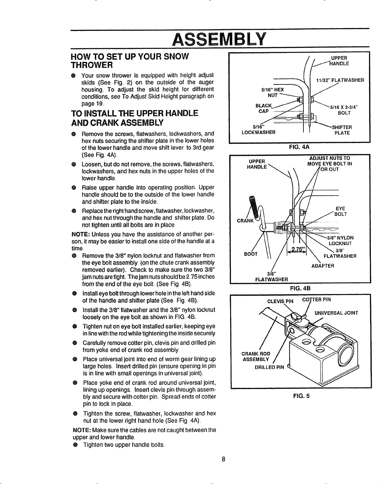
TO INSTALL THE UPPER HANDLE
AND CRANK ASSEMBLY
® Remove the screws, flatwashers, lockwashers, and
hex nuts securing the shifter plate in the lower holes
of the lowerhandle and move shift lever to 3rd gear
(See Fig. 4A)_
@ Loosen, but do not remove, the screws, flatwashers,
tockwashers,and hex nuts in the upper' holes of the
lowerhandle.
® Raise upper handle into operating position. Upper
handle should be to tile outside of the lower handle
and shifter plate to the inside.,
® Replace theright hand screw,flatwasher, Iockwasher,
and hex nut through the handle and shifter plate,.Do
not tighten until all bolts are in place
NOTE: Unless you have the assistance of another per-
son, it may be easier to installone side of the handle at a
time.
® Remove the 3/8" nylon Iocknut and flatwasher from
the eye bolt assembly (on the chute crank assembly
removed eadier). Check to make sure the two 3t8"
jamnuts are tight., The jam nuts should be2.75 inches
from the end of the eye bolt. (See Fig. 4B).
® Install eye bolt through lower holeinthe left hand side
of the handle and shifter plate (See Fig. 4B).
e Install the 3!8" flatwasher and the 3t8" nylon Iocknut
looselyon the eye bolt as shown in FIG 4B.
® Tighten nut on eye bolt installedearlier, keeping eye
in line with the rod while tightening the inside securely
® Carefully remove cotterpin, clevis pinand drilled pin
from yoke end of crank rod assembly.
® Place universal joint into end of worm gear lining up
large holes. Insert drilled pin (ensure opening in pin
is in line with small openings in universal joint).
® Place yoke end of crank rod around universal joint,
lining up openings, Insert clevis pin throughassem-
bly and secure with cotter pin.. Spread ends of cotter
pin to lock in place..
• Tighten the screw, flatwasher, !ockwasher and hex
nut at the lower right hand hole (See Fig 4A).
NOTE: Make sure the cables are not caught between the
upper and lowerhandle,
® Tighten two upper handle boils.
UPPER
)LE
11t32" FLATWASHER
NUT
BLACK 2.3_ ,_
CAP BOLT
5/16" HIFTER
LOCKWASHER PLATE
FIG, 4A
UPPER
HANDLE_,_ MOVE EYE BOLTIN
3/8"
FLAW='ASHER
ADJUSTNUTSTO
OUT
EYE
LOCKNUT
FLATWASHER
ADAPTER
FIG. 4B
CLEVIS PiN 'ER PIN
UNIIVERSALJO]NT
CRANK ROD
ASSEMBLY
DRILLED PIN
FIG. 5
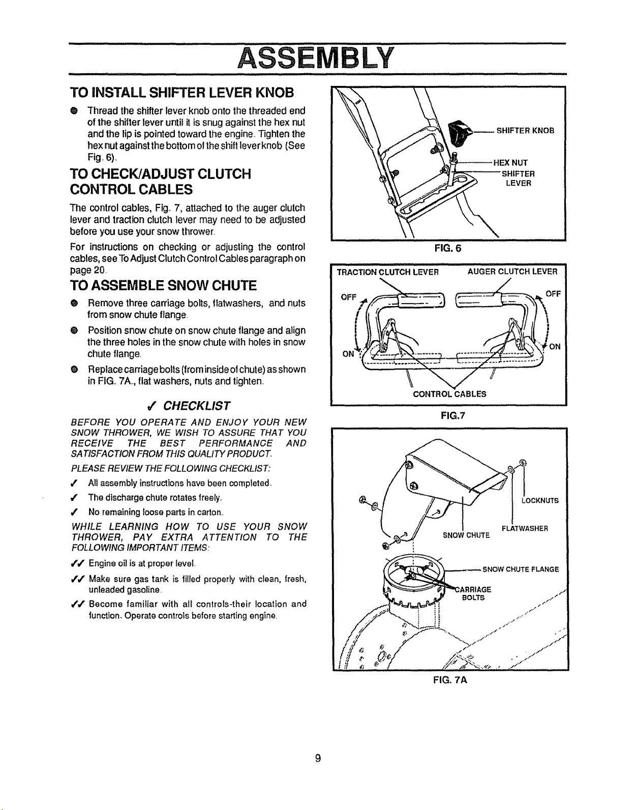
TO iNSTALL SHIFTER LEVER KNOB
@ Thread the shifter lever knob onto the threaded end
of the shifter lever until itissnug against the hex nut
and the lip is pointed toward the engine. Tighten the
hex nutagainst the bottom o! the shiftlever knob (See
Fig. 6).,
TO CHECK/ADJUST CLUTCH
CONTROL CABLES
The control cables, Fig_7, attached to the auger clutch
lever and traction clutch lever may need to be adjusted
before you use your snow thrower.
For instructionson checking or adjusting the control
cables, seeToAdjust Clutch Control Cables paragraph on
page 20.
TO ASSEMBLE SNOW CHUTE
• Remove three carriage bolts, flatwashers, and nuts
from snow chuteflange.
e Position snow chute on snow chute flange and align
the three holes inthe snow chute with holes insnow
chute flange.
e Replace carriage bolts(from inside of chute) asshown
in FIGo7A. flat washers, nuts and tighten..
_/ CHECKLIST
BEFORE YOU OPERATE AND ENJOY YOUR NEW
SNOW THROWER, WE WISH TO ASSURE THAT YOU
RECEIVE THE BEST PERFORMANCE AND
SATISFACTION FROM THIS QUALITY PRODUCT.
PLEASE REVIEW THE FOLLOWING CHECKLIST:
#' All assembly instructionshave been completed.
4' The discharge chute rotates freely.
/ No remaining !oose parts incarton_.
WHILE LEARNING HOW TO USE YOUR SNOW
THROWER, PAY EXTRA ATTENTION TO THE
FOLLOWING IMPORTANT ITEMS:
/./' Engine oil is at proper level.
i'v" Make sure gas tank is filied properly with clean, fresh,
unleaded gasoline.
/,/' Become familiar with all controls-their location and
function.Operate controts before starting engine.
LEVER
FIG. 6
T.A'c:noNcLuTC.L E. Au E"CLuTc,LEVER
CONTROL CABLES
FIG.7
LOCKNUTS
SNOW CHUTE
BOLTS
FLA'TWASHER
FLANGE
_,GE
FIG. 7A
9
......... i iiiillll Ill I I,,11I, ul Ill I ll,,I.
O T
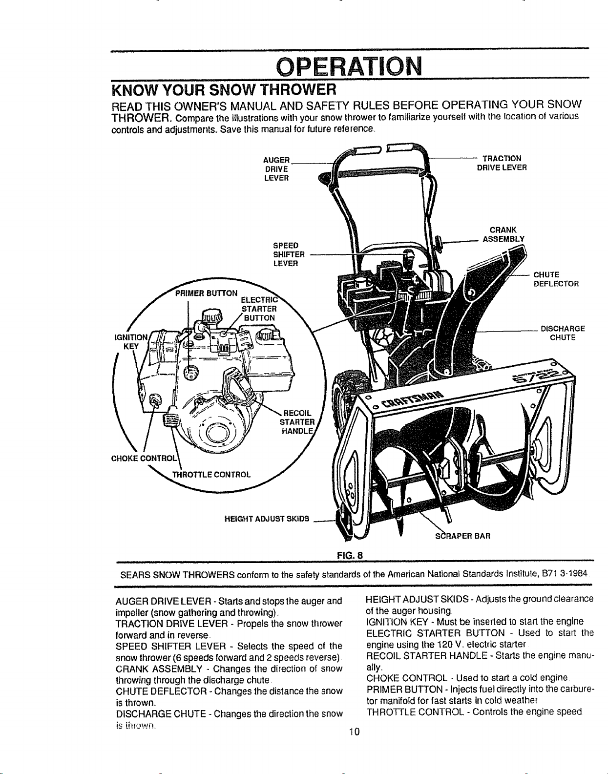
KNOW YOUR SNOW THROWER
READ THIS OWNER'S MANUAL AND SAFETY RULES BEFORE OPERATING YOUR SNOW
THROWER= Compare the illustrationswithyour snow throwerto familiarize yourselfwith the location of various
controlsand adjustment& Save thismanualfor future reference.
AUGER TRACTION
DRIVE DRIVE LEVER
LEVER
CRANK
SPEED
SHIFTER
LEVER
BUTTON
STARTER
KEY
ASSEMBLY
CHUTE
DEFLECTOR
DISCHARGE
CHUTE
STARTER
\
THROTTLE CONTROL
HEIGHT ADJUST SKIDS
HANDLE
S_RAPER BAR
FIG. 8
SEARS SNOW THROWERS conformto the safety standards of the American National Standards Institute, B71 3-1984
........................ . ..... ,,,, , ,,,,,,,,, , ,,,,
AUGER DRIVE LEVER - Starts and stops the auger and
impeller (snow gathering and throwing).,
TRACTION DRIVE LEVER - Propels the snow thrower
forward and in reverse,
SPEED SHIFTER LEVER - Selects the speed of the
snow thrower (6 speeds forward and 2 speeds reverse).
CRANK ASSEMBLY - Changes the direction of snow
throwing through the discharge chute.
CHUTE DEFLECTOR - Changes the distance the snow
is thrown,,
DISCHARGE CHUTE - Changes the direction the snow
is_itrown.
HEIGHT ADJUST SKIDS - Adjusts theground clearance
of the auger housing,
IGNITION KEY - Must be inserted to start the engine
ELECTRIC STARTER BUTTON - Used to start the
engine using the 120 V,. electric starter
RECOIL STARTER HANDLE - Stads the engine manu-
ally,.
CHOKE CONTROL - Used to start a cold engine
PRIMER BUTTON - Injects fuel directty into the carbure-
tor manifofd for fast starts in cold weather
THROTTLE CONTROL - Controls the engine speed
10
OPE
The operation of anysnow thrower can result in foreign objects being thrownintothe
eyes, which can result in severe eye damage. Always wear safety glasses or eye
shields while operating the snow thrower.
We recommend standard safety glasses available at SEARS Retail Stores or
Service Centers
u
These symbols may appear on your unit° Learn and understand their meaning.
TION
ENGINE
START
ENGINE OFF CHOKE FAST SLOW
RUN OFF
TRACTION
DRIVE
CLUTCH
CAUTION: READ OWNER'S MANUAL BE-
FORE OPERATING MACHINE, NEVER
DIRECT DISCHARGE TOWARD BY-
STANDERS. STOP THE ENGINE BEFORE
UNCLOGGING DISCHARGE CHUTE OR
AUGER HOUSING AND BEFORE LEAV-
ING _'HE MACHINE.
HOW TO USE YOU R SNOW
THROWER
AUGER
DRIVE
CLUTCH
STOP FUEL
IGNI_ON KEY
INSERTTO
RUN PULL OUT
TO STOP
WING KNOB
FIG. 9
OIL PRIMER
BUTTON
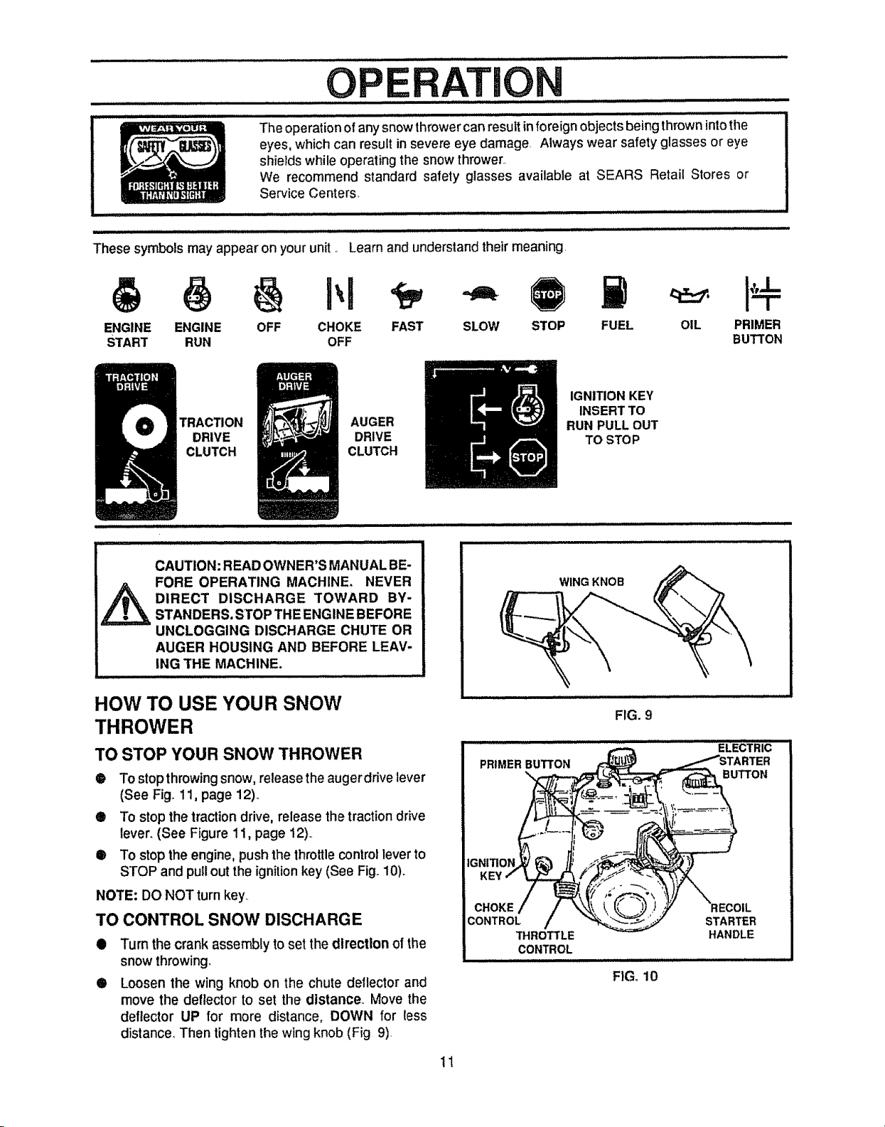
TO STOP YOUR SNOW THROWER
• To stopthrowing snow, release the augerdrive lever
(See Fig. 11, page 12)..
® To stop the traction drive, release the traction drive
lever. (See Figure ! 1, page ! 2),.
® To stop the engine, push the throttle control lever to
STOP and pullout the ignition key (See Fig. 10).
NOTE: DO NOT turn key..
TO CONTROL SNOW DISCHARGE
O
Turn the crank assembly to set the direction of the
snow throwing,
O
Loosen the wing knob on the chute deflector and
move the deflector to set the distance,, Move the
deflector UP for more distance, DOWN for less
distance. Then tighten the wing knob (Fig 9)
11
THROTTLE
CONTROL
STARTER
HANDLE
FIG. 10
/1111 i IIH,
O
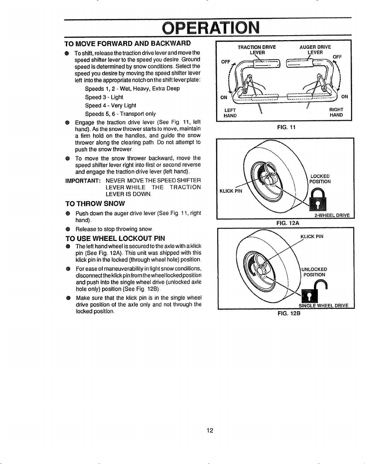
TO MOVE FORWARD AND BACKWARD
@ To shift, re]easethe tractiondrive lever andmovethe
speed shifter lever to the speed youdesire, Ground
speed is determined by snow conditions,,Selectthe
speed you desire by movingthe speedshifterlever
(eft intotheappropriatenotchonthe shiftlever plate:
Speeds 1, 2 - Wet, Heavy, Extra Deep
Speed 3 - Light
Speed 4 - Very Light
Speeds 5, 6 _Transportonly
• Engage the traction drive lever (See Fig 11, left
hand)_As the snow thrower starts to move, maintain
a firm hold on the handles, and guide the snow
thrower along the clearing path Do not attempt to
push the snow thrower.
@ To move the snow thrower backward, move the
speed shifter lever right into first or second reverse
and engage the traction drive lever (left hand).,
IMPORTANT: NEVER MOVE THE SPEED SHIFTER
LEVER WHILE THE TRACTION
LEVER IS DOWN
TO THROW SNOW
@ Push down the auger drive lever (See Fig. 11, right
hand)
@ Release to stop throwing snow.
TO USE WHEEL LOCKOUT PIN
® The left hand wheel is secured tothe axle with aklick
pin (See Fig_!2A). This unit was shipped with this
klick pin in the locked (through wheel hole) position_
Q For ease of maneuverability in light snow conditions,
disconnect the klickpin from the wheel locked position
and push into the single wheel drive (unlocked axle
hole only) position (See Fig. t2B).
® Make sure that the klick pin is in the single wheel
drive position of the axle only and not through the
locked position
ATION
TRACTION DRIVE
LEVER
HAND
KUCK PIN
AUGER DRIVE
LEVER
\
FIGo 11
FIG, 12A
FIG. 12B
/ RIGHT
HAND
LOCKED
POSITION
2-WHEEL DRIVE
KLICK PiN
UNLOCKED
POSITION
SINGLE WHEEL DRIVE
12
i ,,, ,,,,,,,,,,,,,,,,,, ..................................................................
OP T
® If the snowthrowermustbe moved withouttheaidof
theengine,itis easier topullthesnow throwerbythe
handles rather than pushing
O Before you service or start the engine, familiarize
yourself with the snow thrower Be sure you
understand the function and locatfonof allcontrols.
NOTE: Check tension of clutch cables before starting the
engine_(See ToAdjust The Control Cables paragraph on
page 20).
• Be sure that all fasteners are tight
® Make sure the height adjust skids are properly
adjusted (See To Adjust Skid Height paragraph on
page 19)o
® Check tire pressure (14 to 17 pounds) See side of
tire for maximum inflation Do not exceed maximum
pressure
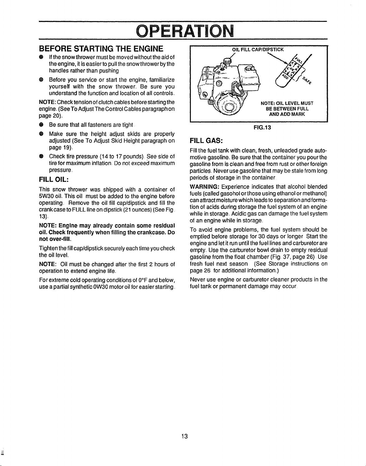
FILL OIL:
This snow thrower was shipped with a container of
5W30 oil. This oil must be added to the engine before
operating Remove the oil fill cap/dipstick and fill the
crankcase to FULL line on dipstick (2t ounces) (See Fig
13).
NOTE: Engine may already contain some residual
oil. Check frequently when filling the crankcase, Do
not over-filL
Tighten the fill cap/dipstick securely each time you check
the oil level
NOTE: Oil must be changed after the first 2 hours of
operation to extend engine life.
For extreme cold operating conditions o! 0°F and below,
use apartial synthetic 0W30 motoroil for easier starting
OIL FILL CAP/DIPSTICKBEFORE STARTING THE ENGINE
NOTE: OIL LEVEL MUST
BE BETWEEN FULL
AND ADD MARK
FIG_13
FILL GAS:
Fill thefuel tank withclean, fresh, unleaded grade auto-
motive gasoline° Be sure that the container you pour the
gasoline from is clean and free from rust or other foreign
particles. Never use gasoline that may be stale from long
periods of storage in the container
WARNING; Experience indicates that alcohol blended
fuels (called gasohol orthose using ethanol ormethanol)
can attract moisture which leads toseparation andforma-
tion of acids during storage the fuel system of an engine
while in storage_Acidic gas can damage the fuel system
of an engine while instorage°
To avoid engine problems, the fuel system should be
emptied before storage for 30 days or longer Start the
engine and let it run until the fuel lines and carburetor are
empty. Use the carburetor bowl drain to empty residual
gasoline from the float chamber (Fig 37, page 26) Use
fresh fuel next season (See Storage instructionson
page 26 for additional information,,)
Never use engine or carburetor cleaner products in the
fuel tank or permanent damage may occur
13
TO STOP ENGINE
® To stop engine, move the throttle control lever to
STOP positionand remove key Keep the key in a
safe place_The enginewiltnotstartwithoutthekey_
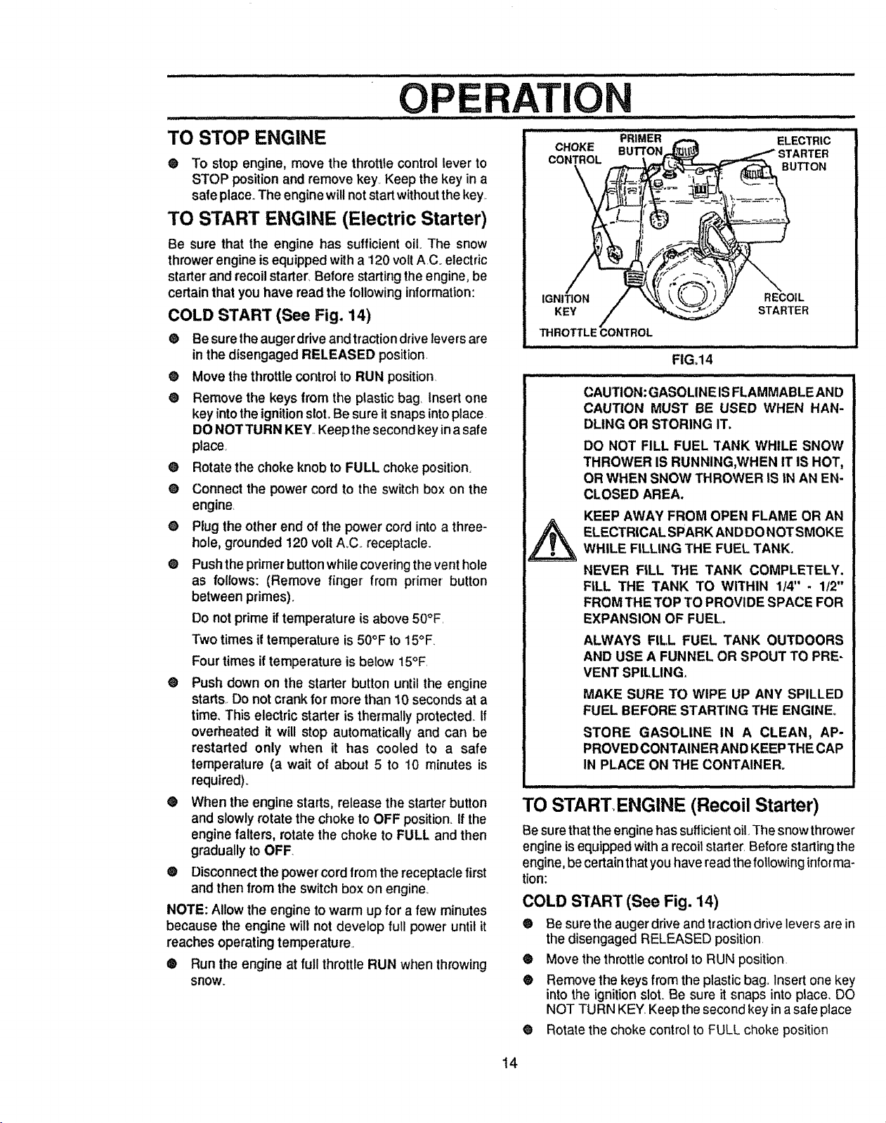
TO START ENGINE (Electric Starter)
Be sure that the engine has sufficientoil. The snow
throwerengine isequippedwith a 120 voltAC_electric
starter and recoil starter, Before starting the engine, be
certain that you have read the following information:
COLD START (See Fig. 14)
® Be sure the auger drive andtraction drive leversare
in the disengaged RELEASED position.
e Move the throttle controlto RUN position
® Remove the keys from the plastic bag, Insert one
key into the ignition slot. Be sure itsnaps intoplace
DO NOTTURN KEY..Keep thesecond key in a safe
place,
@ Rotate the choke knob to FULL choke position.
® Connect the power cord to the switch box on the
engine.
® Plug the other end of the power cord intoa three-
hole, grounded 120 volt A_C..receptacle.
® Pushthe primer button while covering the vent hole
as follows: (Remove finger from primer button
between primes).
Do not prime if temperature is above 50°F.
Two times iftemperature is 50°F to 15°F.
Four times if temperature is below 15°F.
® Push down on the starter button until the engine
starts.. Do not crank for more than 10seconds at a
time, This electric starter isthermally protected_If
overheated it will stop automatically and can be
restarted only when it has cooled to a safe
temperature (a wait of about 5 to 10 minutes is
required).
® When the engine starts, release the starter button
and slowly rotate the choke to OFF position. If the
engine falters, rotate the choke to FULL and then
gradually to OFF.
® Disconnect the powercord from the receptacle first
and then from the switch box on engine.
NOTE: Allow the engine to warm up for a few minutes
because the engine will not develop full power until it
reaches operating temperature.
® Run the engine at full throttle RUN when throwing
snow.
CHOKE BU'FI'ON rER
CONTROL
,_ BUTTON
/
IGNITION RECOIL
KEY STARTER
PRIMER ELECTRIC
FIG,14
CAUTION: GASOLINE ISFLAMMABLE AND
CAUTION MUST BE USED WHEN HAN-
DLING OR STORING IT.
DO NOT FILL FUEL TANK WHILE SNOW
THROWER IS RUNNING,WHEN IT IS HOT,
OR WHEN SNOW THROWER IS IN AN EN-
CLOSED AREA.
KEEP AWAY FROM OPEN FLAME OR AN
ELECTRICAL SPARK ANDDO NOT SMOKE
WHILE FILLING THE FUEL TANK.
NEVER FILL THE TANK COMPLETELY.
FILL THE TANK TO WITHIN 114" - 1t2"
FROM THE TOP TO PROVIDE SPACE FOR
EXPANSION OF FUEL.
ALWAYS FILL FUEL TANK OUTDOORS
AND USE A FUNNEL OR SPOUT TO PRE-
VENT SPILLING.
MAKE SURE TO WIPE UP ANY SPILLED
FUEL BEFORE STARTING THE ENGINE,
STORE GASOLINE IN A CLEAN, AP-
PROVED CONTAINER AND KEEP THE CAP
IN PLACE ON THE CONTAINER_
TO STARTENGINE (Recoil Starter)
Be sure thatthe engine has sufficient oil.The snow thrower
engine is equipped with a recoit starter, Before starting the
engine,be certain that you have readthe foUowinginforma-
rion:
COLD START (See Fig. 14)
® Be sure the augerdfive and tractiondrive levers arein
thedisengaged RELEASED position.
® Move thethrottle controlto RUN position.
® Remove the keysfrom the plasticbag.,Insertone key
intothe ignitionslot. Be sure it snaps into place. DO
NOT TURN KEY Keep thesecond key inasafe place
® Rotate the choke control to FULL choke position
t4
' OPE ...................................AT
CAUTION: NEVER RUN ENGINE
INDOORS OR IN ENCLOSED, POORLY
VENTILATED AREAS°ENGINE EXHAUST
CONTAINS CARBON MONOXIDE, AN
ODORLESS AND DEADLY GAS. KEEP
HANDS, FEET, HAIR AND LOOSE
CLOTHING AWAY FROM ANY MOVING
PARTS ON ENGINE AND SNOW
THROWER.
WARNING: TEMPERATURE OF
MUFFLER AND NEARBY AREAS MAY
EXCEED 150° F. AVOID THESE AREAS.
DO NOT ALLOW CHILDREN OR YOUNG
TEENAGERS TO OPERATE OR BE NEAR
SNOW THROWER WHILE IT IS
OPERATING.
CAUTION: DO NOT ATTEMPT TO RE-
MOVE ANY ITEM THAT MAY BECOME
LODGED IN AUGER WITHOUT TAKING
THE FOLLOWING PRECAUTIONS:
RELEASE AUGER DRIVEAND TRACTION
DRIVE LEVERS,,
- MOVETHROTTLELEVERTOSTOP PO-
SITION.
o REMOVE (DO NOT TURN) IGNITION
KEY.
o DISCONNECT SPARK PLUG WIRE,
• DO NOT PLACE YOUR HANDS IN THE
AUGER OR DISCHARGE CHUTE. USE
A PRY BAR.
O
Push the primer button while covering the vent hole
as follows: (Remove finger from primer button be-
tween primes)_
Do not prime if temperature is above 50°E
Two times iftemperature is 50°F to 15°F
Four times if temperature is below 15°F.
® Pull the recoilstarter handle rapidly.Do not allow the
handleto snap back, but allow ittorewind slowlywhile
keeping a firm hold on the starter handle.
• As the engine warms up and begins to operate
evenly, rotate the choke control slowly to the OFF
position,. If the engine falters, return to FULLchoke,
then slowly move to the OFF position.
NOTE: Allow the engine to warm up for a few minutes
because the engine will not develop full power until it
reaches operatingtemperature,
• Run the engine at full throttle (RUN) when throwing
snow°
WARM START
If restarting a warm engine after ashort shutdown, leave
choke at OFF and do not push the primer button. If the
engine fails to start, follow the Cold Start instructions
above.
FROZEN STARTER
tf the starter is frozen and will not turn engine:
O Pull as much rope out of the starter as possible
• Release the starter handle and let it snap back
against the starter
Ifthe engine still failsto start, push the primer button two
or three times again and repeat the two previous steps
until the engine starts. Then continue with the directions
for cold slart.
To heip prevent possible freeze-up of recoil starter and
engine controls, proceed as follows after each snow
removal job
e With the engine running, pull the starter rope hard
with a continuous full arm stroke three or four times.
Pullingof starter rope will produce a loud clattering
sound This isnot harmlul to the engine or starter.
e With the engine not running, wipe all snow and
moisture fromthe carburetor cover inarea ofcontrol
levers. Also move throttle control, choke control, and
starter handte several times
SNOW THROWING TIPS
e For maximum snow thrower efficiency in removing
snow, adjust ground speed, NEVER the throttle.. Go
slower in deep, freezing, or wet snow. tf the track
slips, reduce forward speed, The engine is designed
to deliver maximum pedormance at full throttle and
should be run at this power setting at alltimes
e Most efficient snow throwing isaccomplished when
the snow is removed immediately after it falls.
® For complete snow removal, slightly overlap each
path previously taken.
e The snow should be discharged down windwhenever
possible_
@ For normal usage, set the skids so that the scraper
bar is 1/8"above the skids. For extremely hardpacked
snow surfaces, adjust the skids upward so that the
scraper bar touches the ground.
O On gravel orcrushed rock sudaces, set the skids at
1-1/4" below the scraper bar (see To Adjust Skid
Height paragraph on page 19). Stones and gravel
must not be picked up and thrown by the machine
• After the snow throwing job has been completed,
allow the engine to idle fora few minutes, whichwill
melt snow and accumulated ice off the engine
• Clean the snow thrower thoroughlyafter each use
I, Remove ice and snow accumufation and all debris
from the entire snow thrower, and flush with warer(if
possible) to remove all salt or other chemicals Wipe
snow thrower dry.
15
CUSTOM ILITI
J .,,,,,,,,
,,,uL.... ,,J,..................
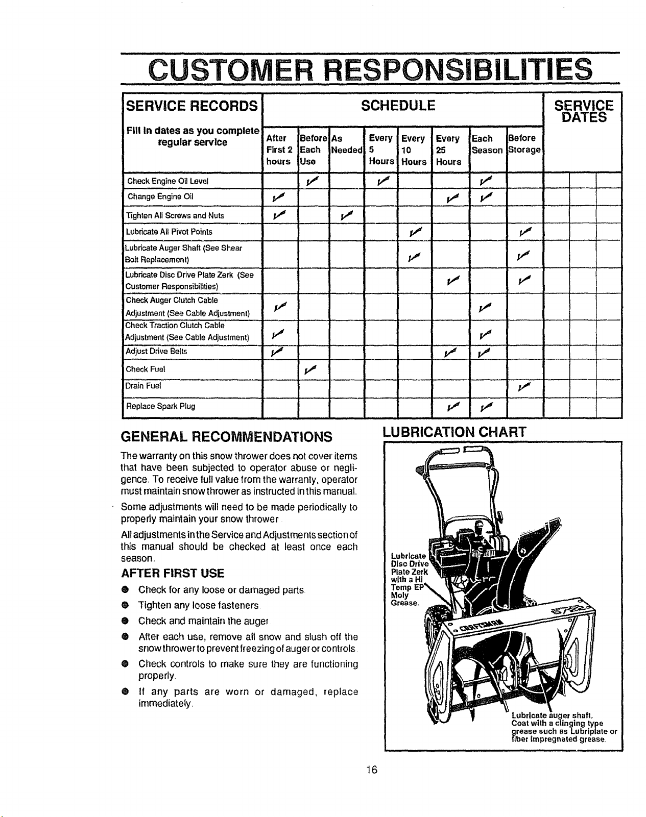
SERVICE RECORDS
Fill in dates as you complete
regular service After Before As
Check Engine Oil Level _ pJ
Change Engine Oil _
Tighten Al! Screws and Nuts PJ .............. PJ I......
Lub,=teA,Pi,otPoint, V" _'
Lubricate Auger Shaft (See Shear
Bolt Replacement) _ PJ
Lubricate Disc Drive Plate Zerk (See
Customer Responsibilities) PJ PJ
iCheck Auger Clutch Cable
Adjustment (See Cable Adjustment) PJ
Check Traction ciUtch Cable ' i
Adjustment (See Cable Adjustment) _
AdjustD,iveSe,_ _" 11 I,"
Check Fuel
Drain Fuel
First2 Each Needed
hours Use
- = =
, , ,......... , ,,,,,.......
,,,,, ,,,
SCHEDULE
Every IEvery Every Each Before
5 10 25 Season Storage
Hours Hours Hours
J
SERVICE
DATES
Replace Spark Ptug
GENERAL RECOMMENDATIONS
The warranty on thissnowthrowerdoes notcover items
that have been subjected to operator' abuse or negli-
gence, To receive full value from thewarranty, operator
must maintain snow thrower as instructed inthismanuat..
Some adjustments will need to be made periodically to
properly maintain your snow thrower
All adjustments inthe Service and Adjustments section of
this manual should be checked at least once each
season,,
AFTER FIRST USE
® Check for any loose or damaged parts.
® Tighten any loose fasteners.
® Check and maintain the auger
® After each use, remove all snow and slush off the
snow throwerto prevent freezing ofauger orcontrols
® Check controls to make sure they are functioning
properly,
® If any parts are worn or damaged, replace
irnmediately.
LUBRICATION CHART
Lubricate
Diso Drive
Plate Zerk
Moly
rease,,
Coat with a clinging type
grease such as Lubriplate or
fiber Impregnated grease_
Pate auger shafL
16
............ i i i ill ii ,,ll ,lllll,i,illllllllllllll
' CUSTO.........
SNOW THROWER
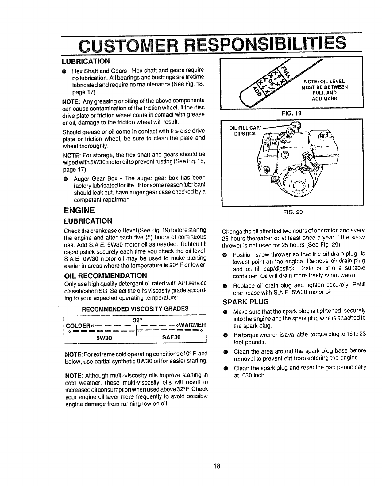
LUBRICATION - EVERY TEN HOURS
@ Auger Shaft- For storage, lubricate auger shaft ( See
Fig, 16)with aclinging type grease such asLubriplate.
When replacing shear bolts, remove shear bolts and
lubricate auger shaft (see To Replace Shear Bolt
paragraph on page 24).,
@ See Lubrication Chart diagram on page 16 for
lubrication points and type of lubricant,
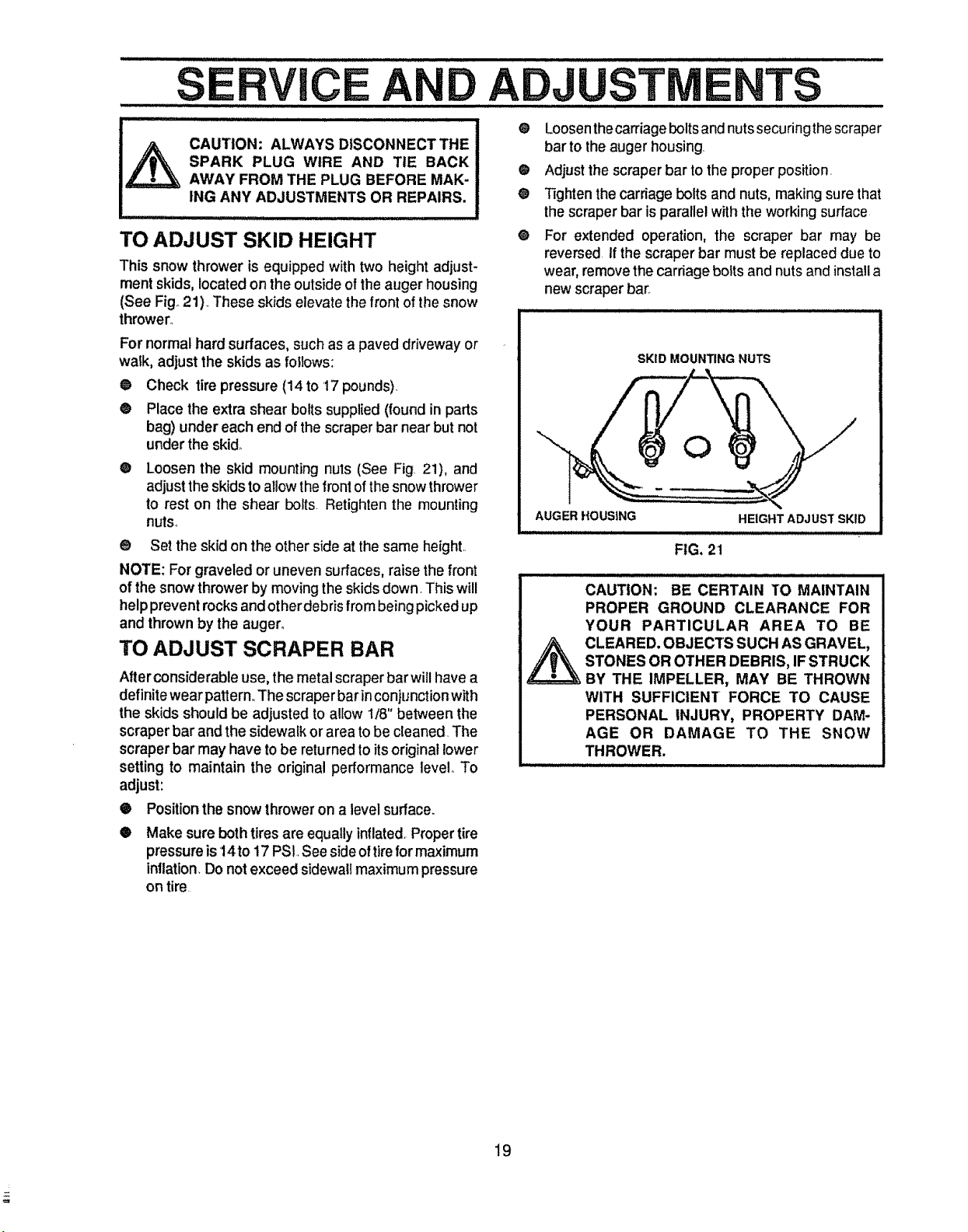
LUBRICATION - EVERY 25 HOURS
@ Lubricate Disc Drive Plate every 25 hours and at the
end of the season and/or before storage,
To Lubricate:
@ Position speed selector lever in first gear
@ Tum disc drive plate clockwise by hand until grease
zerk is clearly visible at front center (see Fig. 18)
@ Place a coin or (a shim of equal thickness) between
the rubberfdction wheel and disc drive plate to pre-
vent rubber friction wheel contacting the drive disc,
@ Togrease zerk, use a hand grease gun, lubricate with
a Hi Temp EP Moly grease, (see Fig, 18 inset) DO
NOT over fill or allow grease to come in contact with
the disc drive plate or friction wheel or damage will
resulL Fill zerk only until grease becomes visible
below bearing assembly located under grease zerk,
(see Fig 18 inset)
IMPORTANT; Remove coin and ensure that a gap
exists between friction wheel and disc drive plate.
NOTE: Clean all excess grease found on friction disc hub.
CAUTION; Do not allow grease to contact friction wheel
and disc drive plate,
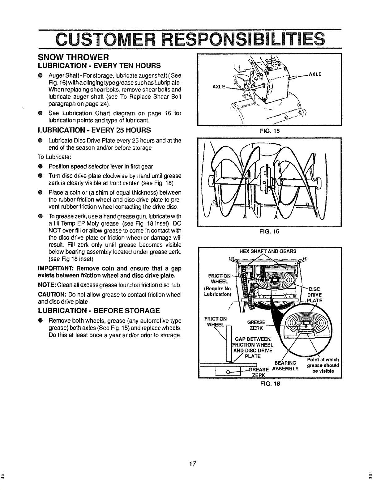
LUBRICATION - BEFORE STORAGE
@ Remove both wheels, grease (any automolive type
grease) both axles (See Fig 15) and replacewheels
Do this at least once a year and/or prior to storage,
AXLE
FRICTION
WHEEL
(Require No
Lubrication)
FRICTION
WHEEL
i ILmTES
'_,
FIG. 15
FIG. 16
HEX SHAFT AND GEARS
/
/
GREASE
ZERK
GAP BETWEEN
:RiCTION WHEEL
DISC DRIVE
........AXLE
i i / iiii
DRIVE
..,PLATE
17
FIG. 18
.......................................................................................................... , ,, ,,,, ...............................
CUSTOM ILITIES
LUBRICATION .........
® Hex Shaft and Gears - Hex shaft and gears require
no lubrication All bearings and bushings are lifetime
lubricated and require no maintenance (See Fig. 18,
page 17).
NOTE: Any greasing or oiling of the above components
can cause contamination of the friction wheel Ifthe disc
ddve plate or friction wheel come in contact with grease
or oil, damage to the friction wheel willresult.,
Should grease or oil come in contact with the disc drive
plate or friction wheel, be sure to clean the plate and
wheel thoroughly_
NOTE: For storage, the hex shaft and gears should be
wipedwith 5W30 motor oitto prevent rusting(See Fig. t8,
page 17).
@ Auger Gear Box - The auger gear box has been
factory lubricated for life. if for some reason lubricant
should leak out, have auger gear case checked by a
competent repairman.
ENGINE
LUBRICATION
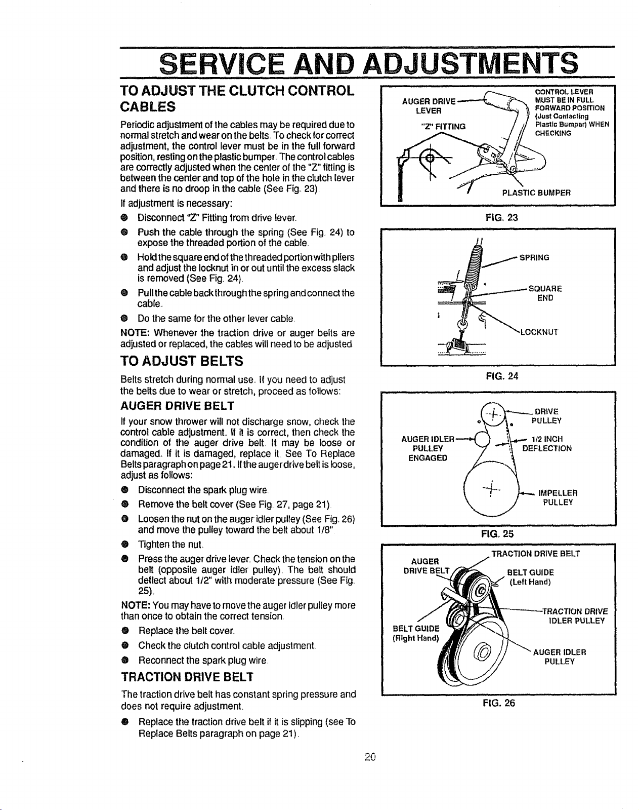
Check the crankcase oil level (See Fig. 19)before startng
the engine and after each five (5) hours of continuous
use.,Add S.,A.E. 5W30 motor oil as needed. Tighten fill
cap/dipstick securely each time you check the oil Ievel,
SrAE 0W30 motor oil may be used to make starting
easier in areas where the temperature is 20° For lower.
OIL RECOMMENDATION
Only use high quality detergent oil ratedwith API service
classification SG Select the oi!'s viscosity grade accord-
ing to your expected operating temperature:
RECOMMENDED VISCOSITY GRADES
LDER_€ .{ _WARMER
5W30 SAE30
NOTE: Forextreme cold operating conditions of0° F and
below, use partial synthetic0W30 oilfor easier starting
NOTE: Although multi-viscosity oils improve starting in
cold weather, these multi-viscosityoils will result in
increasedoilconsumptionwhen used above32°F Check
your engine oil level more frequently to avoid possible
engine damage from running low on oil,,
i, i i i i ....,i lira. I II.lJ IL i HI] ,,i m.,
Change theoil after first two hours ofoperation and every
25 hours thereafter or at least once a year if the snow
thrower is not used for 25 hours (See Fig 20)
e Position snow thrower so that the oil drain plug is
_owestpoint on the engine Remove oil drain plug
and oil fill capfdipstick Drain oil into a suitable
container. Oil will drain more freely when warm
0 Replace oil drain plug and tighten securely Refill
crankcase with S.AE 5W30 motor oil
SPARK PLUG
• Make sure that the spark plug is tightened securely
into the engine andthe spark plug wire is attached to
the spark plug
® ifa torque wrench isavailable, torque plug to 18 to23
foot pounds,
® Clean the area around the spark plug base before
removal to prevent dirt from entering the engine
® Clean the spark plug and reset the gap periodically
at .030 inch.
FIG. 19
FIG. 20
18
_ CAUTION: ALWAYS DISCONNECT THE
SPARK PLUG WIRE AND TiE BACK
AWAY FROM THE PLUG BEFORE MAK-
ING ANY ADJUSTMENTS OR REPAIRS.
TO ADJUST SKID HEIGHT
This snow thrower is equipped with two height adjust-
ment skids, located on the outside of the auger housing
(See Fig°21). These skids elevate the front of the snow
thrower°
• Loosenthecarriage boltsand nuts securingthe scraper
bar to the auger housing.
® Adjust the scraper bar to the proper position.
@ Tighten the carriage bolts and nuts, making sure that
the scraper bar is parallel with the working surface
@ For extended operation, the scraper bar may be
reversed if the scraper bar must be replaced due to
wear, remove the carriage bolts and nuts and install a
new scraper bar_
For normal hard surfaces, such as apaved driveway or
walk, adjust the skids as follows:
@
Check tire pressure (14 to 17 pounds).
@
Place the extra shear bolts supplied (found in parts
bag) under each end of the scraper bar near but not
under the skid_
O
Loosen the skid mounting nuts (See Fig 21), and
adjust the skids to allow the frontof the snow thrower
to rest on the shear bolts. Retighten the mounting
nuts_
® Set the skid on the other side at the same height..
NOTE: For graveled or uneven surfaces, raise the front
of the snow thrower by moving the skids down. This will
help prevent rocks and other debris from being picked up
and thrown by the auger°
TO ADJUST SCRAPER BAR
After considerable use, the metal scraper barwifl have a
definite wear pattern,.The scraper bar inconjunction with
the skids should be adjusted to allow 1t8" between the
scraper bar and the sidewalk or area to be cleaned. The
scraper bar may have to be returned toitsoriginal lower
setting to maintain the original performance level_To
adjust:
• Position the snow thrower on a level surface.
O
Make sure both tiresare equally inflated,Propertire
pressure is 14to 17 PSt,See side oftire formaximum
inflation, Do not exceed sidewall maximum pressure
on tire.
SKID MOUNTING NUTS
AUGER HOUSING
FiG, 21
CAUTION: BE CERTAIN TO MAINTAIN
PROPER GROUND CLEARANCE FOR
YOUR PARTICULAR AREA TO BE
_ CLEARED. OBJECTS SUCH AS GRAVEL,
STONES OR OTHER DEBRIS, IF STRUCK
BY THE IMPELLER, MAY BE THROWN
WITH SUFFICIENT FORCE TO CAUSE
PERSONAL INJURY, PROPERTY DAM-
AGE OR DAMAGE TO THE SNOW
THROWER.
HEIGHT ADJUST SKID
!9
Periodic adjustment of the cables may be required due to
normal stretch and wear on the belts. Tocheck for correct
adjustment, the control lever must be in the full forward
position, restingonthe plasticbumper._The control cables
are correctly adjusted when the center of the "Z" fitting is
between the center and top ofthe hole inthe ctutch lever
and there is no droop in the cable (See Fig._23)
If adjustment is necessary:
® Disconnect "Z" Fitting from drive lever,
@ Push the cable through the spring (See Fig 24) to
expose the threaded portion of the cable
® Holdthe square er_ofthe threaded portionwith pliers
and adjust the Iocknut inor out until the excess slack
is removed(See Fig.24),
@ Pullthe cable backthroughthe springand connect the
cable°
@ Do the same for'the otherlever cable,
NOTE: Whenever the traction drive or auger belts are
adjusted or replaced, the cabtes willneed to be adjusted
TO ADJUST BELTS
Belts stretch during norrnal use._Ifyou need to adjust
the belts due to wear or stretch, proceed as follows:
AUGER DRIVE BELT
Ifyour snow thrower will not discharge snow, check the
control cable adjustmenL if it is correct, then check the
condition of the auger drive belt. It may be loose or
damaged., If it is damaged, replace it See To Replace
Belts paragraph on page2t., Ifthe auger drivebelt isloose,
adjust as follows:
® Disconnect the spark plug wire.
® Remove the belt cover (See Fig 27, page 21)
® Loosen the nut on the auger idlerpulley (See Fig 26)
and movethe pulley toward the belt about t/8"
® Tighten the nut..
® Press the auger drive lever, Check the tension onthe
belt (opposite auger idler pulley). The belt should
deflect about 112"with moderate pressure (See Fig.
25),
NOTE: You may have tomove the auger idlerpulley more
than once to obtain the correct tension
® Replace the belt cover..
® Check the clutch control cable adjustment,.
® Reconnect the spark plug wire
TRACTION DRIVE BELT
AUGER MUST REIN FULL
LEVER FORWARD POSmON
"Z" FITTING Plastic Bumper) WHEN
PLASI']C BUMPER
(Just Contacting
CHECKING
FIG, 23
,__/SPRING
,LOCKNUT
FIG. 24
DR|VE
PULLEY
PULLEY
ENGAGED
112INCH
DEFLECTION
IMPELLER
PULLEY
FIG, 25
I I /I IIIIIIII II II IIII II IIIIII
AUGER
DRIVE BELT BELT GUI DE
BELT GUIDE
(Right Hand)
_TRACTION DRIVE BELT
(Left Hand)
AUGER IDLER
PULLEY
IDLER PULLEY
!IVE
The traction drive belt has constant spring pressure and
does not requireadjustment.
® Replace the traction drive belt if it isslipping (see To
Replace Belts paragraph on page 21).
FIG. 26
.....SE ....................CE ADJ.................................................................TS
TO REPLACE BELTS
The drive belts on this snow thrower are of special
construction and should be replaced with original
equipmentbelts available from yournearest Sears Store
or Service Center.
You will need the assistance of a second personwhile
replacingthe belts.
Drainthegasolinefrom the fu el tankby removingthefuel
liner Drain the gas and reinstallthe fuel line
X 1/2 INCH SELF
DOORS, AWAY FROM FIRE OR FLAME.
AUGER DRIVE BELT
If your snow thrower will not discharge snow, and the
auger drive belt is damaged, replace it as follows:
® Disconnect the spark plug wire
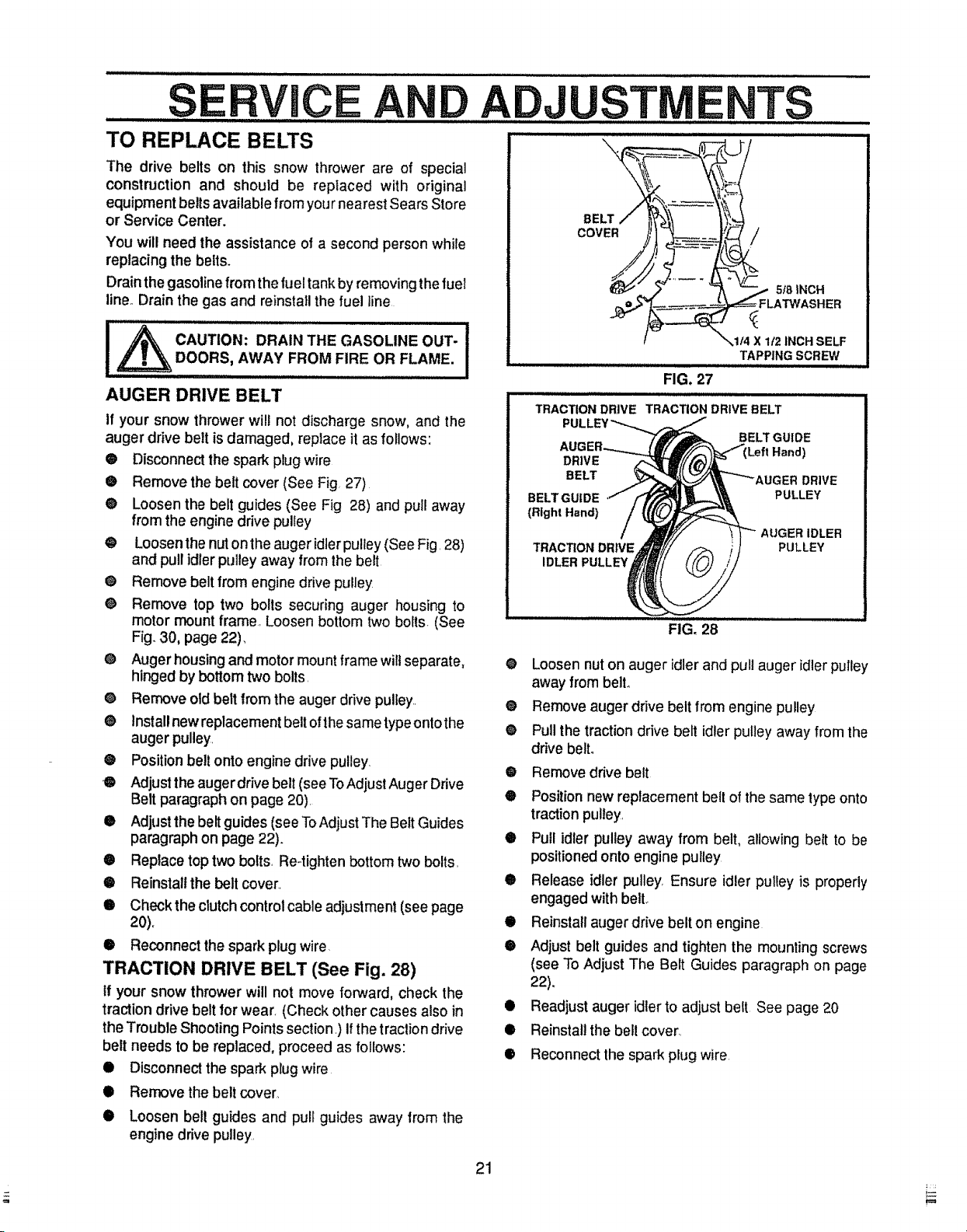
• Remove the belt cover (See Fig 27)
@ Loosen the belt guides (See Fig 28) and pull away
from the engine drive pulley
@ Loosen the nut onthe auger idler pulley (SeeFig. 28)
and pull idler pulley away from the belt
@ Remove belt from engine drive pulley
@ Remove top two bolls securing auger housing to
motor mount frame, Loosen bottom two bolts. (See
Fig. 30, page 22),
@ Auger housing and motor mount frame wilt separate,
hinged by bottom two bolls.
@ Remove old belt from the auger drive pulley..
@ Install new replacement beltof thesame typeontothe
auger pulley.
@ Position belt onto engine drive pulley.
O Adjust theauger drive belt (seeToAdjust Auger Drive
Belt paragraph on page 20).
• Adjust the belt guides (seeToAdjust The Belt Guides
paragraph on page 22).
• Replace top two bolts, Re-tighten bottom two bolts.
• Reinstall the belt cover_
@ Check the clutch control cable adjustment (see page
20).
@ Reconnect the spark plug wire.
TRACTION DRIVE BELT (See Fig. 28)
tf your snow thrower will not move forward, check the
traction drive belt for wear. (Check other causes also in
the Trouble Shooting Points section.) if the traction drive
belt needs to be replaced, proceed as follows:
• Disconnect the spark plug wire
@ Remove the belt cover,
@ Loosen bell guides and pull guides away from the
engine drive pulley.
FIG. 27
iiii ilJlllllllllllllllllllllliji1¸/111i i
TRACTION DRIVE TRACTION DRIVE BELT
DRIVE
BELT
BELT GUIDE
(Bight Hand)
TRACTION DRIVE
IDLER PULLEY
FIG, 28
@
Loosen nuton auger idlerand pull auger idler pulley
away from belt@
@
Remove auger drive belt from engine pulley
®
Pull the traction drive belt idler pulley away from the
drive belt.
0
Remove drive belt
@
Positionnew replacement belt of thesame type onto
traction pulley.
@
Pull idler pulley away from belt, allowing belt to be
positioned onto engine pulley
@
Release idler pulley Ensure idler pulley is properly
engaged with bell
@
Reinstall auger drive belt on engine
®
Adjust belt guides and tighten the mounting screws
(see To Adjust The Belt Guides paragraph on page
22).
0
Readjust auger idler to adjust belt See page 20
0
Reinstall the bell cover.
®
Reconnect the spark plug wire
TAPPING SCREW
BELT GUIDE
PULLEY
AUGER IDLER
PULLEY
iiiiHu
DRIVE
21
S ...........CE ADJUST ..........TS
......... ..... Jl iiiii u i iiiiiii ,111,,,i / ,, ................ii : : : ................................... .
TO ADJUST THE BELT GUIDES ...................... .........................
® Disconnect the spark plugwire.
® Remove the belt cover by removing the screw and
flatwasheron the leftand right hand sides See Fig 27,
page 21_
Q Engage the auger drive clutch lever.
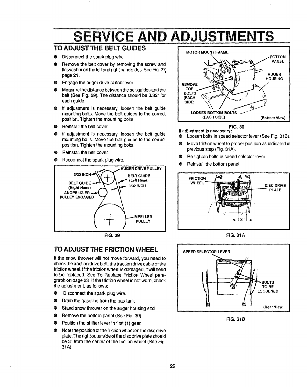
® Measurethe distance betweenthe beltguides and the
belt (See Fig..29). The distance should be 3/32" for
each guide.,
@ tf adjustment is necessary, loosen the belt guide
mounting bolts. Move the beit guides to the correct
position,.Tighten the mounting bolts.
® Reinstall the belt cover.
® If adjustment is necessary, loosen the belt guide
mounting bolts. Move the belt guides to the correct
position. Tighten the mounting bolts
®
Reinstall thebelt cover.
®
Reconnect the spark plug wire.
........" : ......... ,--_ -,,-,,_,...__ AUaER_RiVEPULLEY
3132
1NCH'W_ ._,.,. _ BELT GUIDE
,4,.-.-\W
3132INCH
MOTOR MOUNT FRAME
PANEL
AUGER
HOUSING
REMOVE
TOP
BOLTS
(EACH
(EACH SLOE)
(Bottom View}
FIG. 30
If adjustmentisnecessary:
® Loosen bolts in speed selector lever (See Fig 31B)
• Move friction wheel to proper positionas indicatedin
previous step (Fig 3tA)..
®
Re-tighten boltsin speed selector lever
O
Reinstall the bottom panel.
FRICTION
DISC DRIVE
PLATE
I .d _...-IMPELLER
_ T-'" ) PULLEY
FIG. 29
TO ADJUST THE FRICTION WHEEL
If the snowthrower will not move forward, you need to
checkthetractiondrive belt,thetractiondrivecableorthe
fdction wheel Ifthefriction wheel is damaged,itwill need
to be replaced_See To Replace FrictionWheel para-
graphon page 23. Ifthe frictionwheel is notworn, check
the adjustment, as follows:
® Disconnectthe spark plugwire°
® Drainthe gasolinefrom the gas tank
® Stand snowthroweron the auger housing end.
® Remove the bottom panel (See Fig 30)..
® Positionthe shifter lever in first(1) gear.
• Notethe positionofthefriction wheelonthe disc drive
plate.The rightouterside of thedisc drive plateshould
be 3" from the center of the friction wheel (See Fig.
31A).
/
p
!
SPEED SELECTOR LEVER
_...- - ........ .. __ .......
FIG. 31A
=_BOLTS
TO BE
LOOSENED
(Rear View)
FIG. 31B
22
S CE ADJUSTNIE TS
TO REPLACE FRICTION WHEEL BOLT
FRICTION
WHEEL
Ifthe snow thrower willnot move forward, and the friclion
wheel is worn or damaged, you need to replace it as
LOCKWASHER
follows: (First allow the engine to cool.)
_ CAUTION: DRAIN GASOLINEOUTDOORS
AWAY FROM FIRE OR FLAME.
® Drainthe gasoline from the fuel tank by removing the
fuel line. Drain the fuel and reinstall the fuet line
Q Disconnect the spark plugwire
@ Stand the snow thrower up onthe auger housing end
HUB
NUT
LOCKWASHER
(See Fig. 33)_
® Remove thebottom panel (See Fig 30, page 22)_
FIG. 32
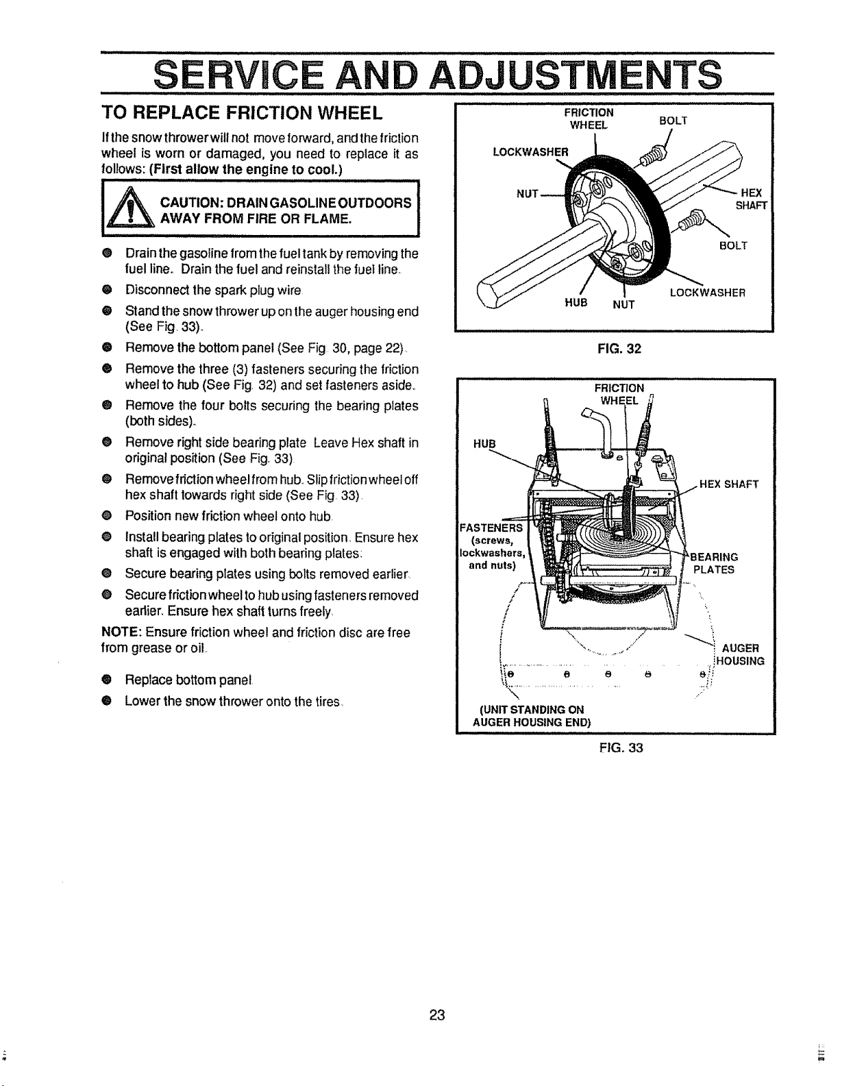
® Remove the three (3) fasteners securing the friction
wheel to hub (See Fig. 32) and set fasteners aside,.
FRICTION
@ Remove the four bolts securing the bearing plates
(both sides).
@ Remove right side bearing plate Leave Hex shaft in
HUB
original position (See Fig. 33)
® Removefriclionwheelfromhub..Slipfrictionwheeloff
hex shaft towards right side (See Fig. 33).
O Position new friction wheel onto hub.
• Install bearing plates to original position. Ensure hex
shaft is engaged with both bearing plates:
@ Secure bearing plates using bolts removed earlier.
FASTENERS
(screws,
Iockwashers,
and nuts)
@ Secure friction wheel to hub using fasteners removed
eadier. Ensure hex shaft turns freely
NOTE: Ensure friction wheel and friction disc are free
from grease or oil
• Replace bottom panel
@ Lowerthe snow throweronto the tires,
"_K_............................. ..::i._
(UNIT STANDING ON
AUGER HOUSING END)
".... '/ _ AUGER
%,. . J _"
SHAFT
BOLT
SHAFT
PLATES
L
,,iHOUSING
23
FIG. 33
 Loading...